

Page 1
harman/kardon
DVD 16 and 18 /230V Service Manual
Page 1 of 39
harman/kardon Service Manual
DVD 16/230
DVD 18/230
DVD players
Only sold with AVR 139 and AVR 141 as AVR/DVD combos 13916, 13918, 14116, 14118..
ESD PRECAUTIONS 2
SERVICING PRECAUTIONS
OWNER’S MANUAL FR
OM TABLE OF CONTEN
REMOTE CONTR
AVR/DVD S
FEATURES 12
FRONT PANEL CONTROLS
REAR
SETUP A
YSTEM CONNECTI
PANEL CONNECTIONS
ND CONNEC
ONT PAGE 5
TS 6
OL FUNCTIONS 7
TIONS 15
Released EU2010 Harman Consumer Group, Inc. Rev 0, 09/2010
8500 Balboa Boulevard.
Northridge, California 91329
CONTENTS
3
ONS 11
13
14
TROUBLESHOOTING GUIDE 16
TECHNICAL SPECIFICATIONS 17
SOFTWARE CHECK +
TROUBLESHOOTING CHARTS
XPLODED VIEW
E
DVD 16 SERVICE PART
DVD 18 SERVICE PART
PCB
DRAW
WIRING DIAGRAM
SCHEMATI
INGS
C DIAGRAMS
UPGRADE 18
19
24
S 25
S 26
27
31
32-39
Page 2

harman/kardon
DVD 16 and 18 /230V Service Manual
Page 2 of 39
ESD PRECAUTIONS
Electrostatically Sensitive Devices (ESD)
Some semiconductor (solid state) devices can be damaged easily by static electricity . Such components commonly are called Electrostatically Sensitive Devices (ESD). Examples of typical ESD devices are integrated cir cuits and some field-effect transistors and semiconductor chip components. The following techniques should
be used to help reduce the incidence of component damage caused by static electricity .
1. Immediately before handling any semiconductor component or semiconductor-equipped assembly, drain off
any electrostatic charge on your body by touching a known earth ground. Alternatively, obtain and wear a
commercially available discharging wrist strap device, which should be removed for potential shock reasons
prior to applying power to the unit under test.
2. After removing an electrical assembly equipped with ESD devices, place the assembly on a conductive sur face such as aluminum foil, to prevent electrostatic charge buildup or exposure of the assembly .
3. Use only a grounded-tip soldering iron to solder or unsolder ESD devices.
4. Use only an anti-static solder removal device. Some solder removal devices not classified as "anti-static"
can generate electrical charges sufficient to damage ESD devices.
5. Do not use freon-propelled chemicals. These can generate electrical charges sufficient to damage ESD
devices.
6. Do not remove a replacement ESD device from its protective package until immediately before you are
ready to install it. (Most replacement ESD devices are packaged with leads electrically shorted together by
conductive foam, aluminum foil or comparable conductive materials).
7. Immediately before removing the protective material from the leads of a replacement ESD device, touch the
protective material to the chassis or circuit assembly into which the device will by installed.
CAUTION : BE SURE NO POWER IS APPLIED TO THE CHASSIS OR CIRCUIT, AND OBSERVE ALL
OTHER SAFETY PRECAUTIONS.
8. Minimize bodily motions when handing unpackaged replacement ESD devices. (Otherwise harmless motion
such as the brushing together of your clothes fabric or the lifting of your foot from a carpeted floor can gen erate static electricity sufficient to damage an ESD device).
Page 3
SERVICING PRECAUTIONS
NOTES REGARDING HANDLING OF THE PICK-UP
1. Notes for transport and storage
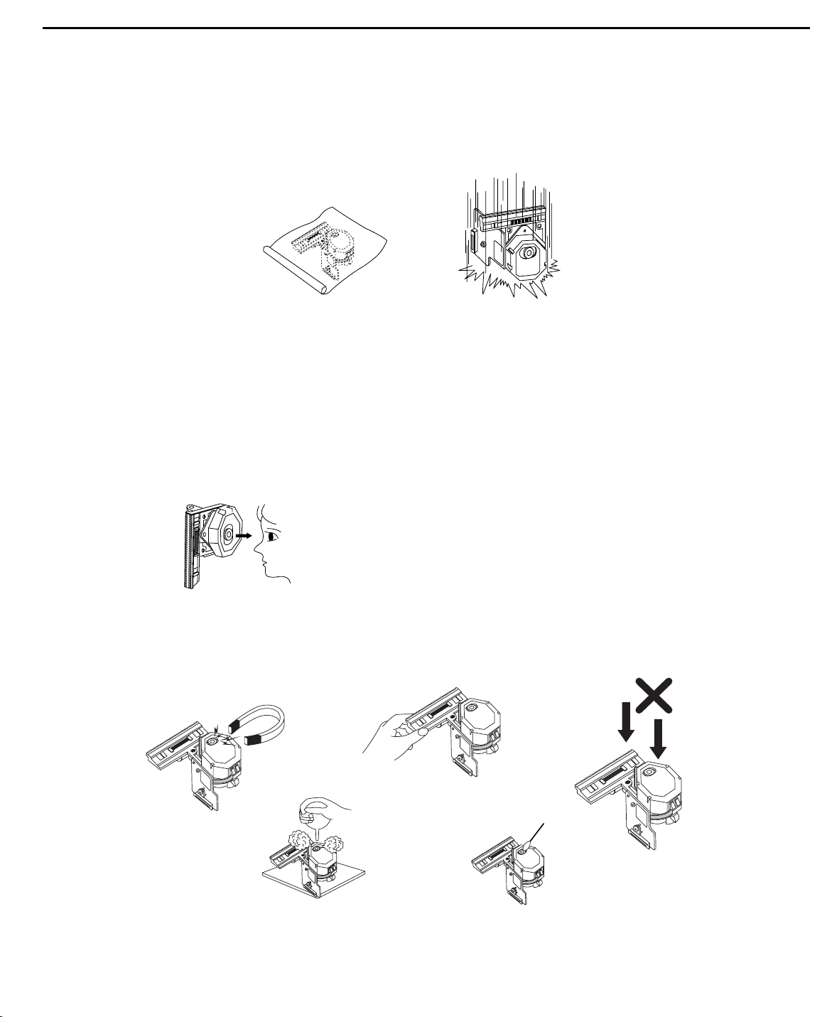
1) The pick-up should always be left in its conductive bag until immediately prior to use.
2) The pick-up should never be subjected to external pressure or impact.
2. Repair notes
1) The pick-up incorporates a strong magnet, and so should never be brought close to magnetic materials.
2) The pick-up should always be handled correctly and carefully, taking care to avoid external pressure and
impact. If it is subjected to strong pressure or impact, the result may be an operational malfunction
and/or damage to the printed-circuit board.
3) Each and every pick-up is already individually adjusted to a high degree of precision, and for that reason
the adjustment point and installation
screws should absolutely never be touched.
4) Laser beams may damage the eyes!
Absolutely never permit laser beams to enter the eyes!
Also NEVER switch ON the power to the laser output part (lens, etc.) of the pick-up if it is damaged.
5) Cleaning the lens surface
If there is dust on the lens surface, the dust should be cleaned away by using an air bush (such as used
for camera lens). The lens is held by a delicate spring. When cleaning the lens surface, therefore, a cot ton swab should be used, taking care not to distort this.
6) Never attempt to disassemble the pick-up.
Spring by excess pressure. If the lens is extremely dirty, apply isopropyl alcohol to the cotton swab. (Do
not use any other liquid cleaners, because they will damage the lens.) Take care not to use too much of
this alcohol on the swab, and do not allow the alcohol to get inside the pick-up.
Storage in conductive bag
NEVER look directly at the laser beam, and don’t let contact
fingers or other exposed skin.
Magnet
How to hold the pick-up
Conductive Sheet
Cotton swab
Pressure
Pressure
Drop impact
harman/kardon
DVD 16 and 18 /230V Service Manual
Page 3 of 39
Page 4
NOTES REGARDING COMPACT DISC PLAYER REPAIRS
1. Preparations
1) Compact disc players incorporate a great many ICs as well as the pick-up (laser diode). These components are sensitive to, and easily af fected by, static electricity. If such static electricity is high voltage,
components can be damaged, and for that reason components should be handled with care.
2) The pick-up is composed of many optical components and other high-precision components. Care must
be taken, therefore, to avoid repair or storage where the temperature of humidity is high, where strong
magnetism is present, or where there is excessive dust.
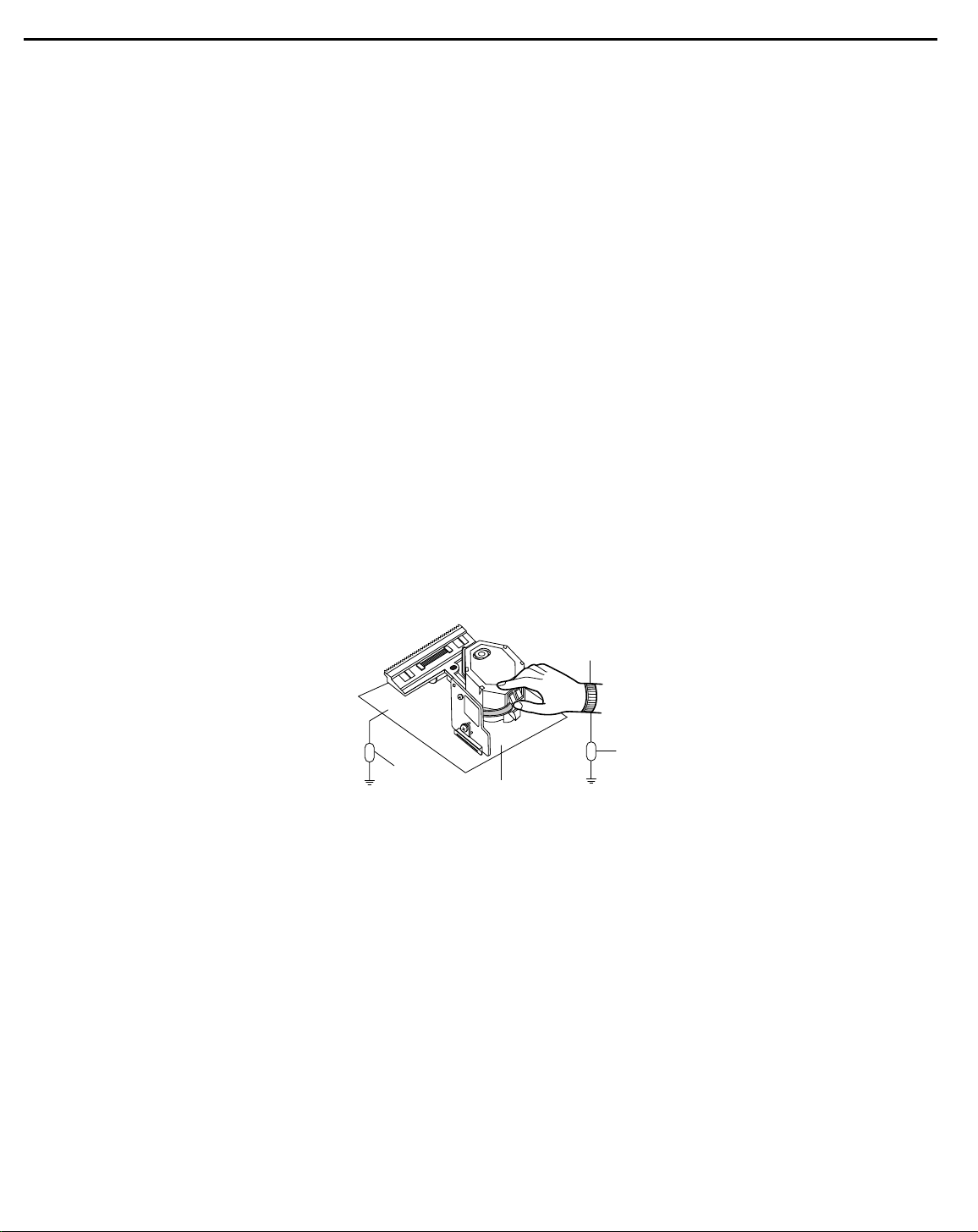
2. Notes for repair
1) Before replacing a component part, first disconnect the power supply lead wire from the unit
2) All equipment, measuring instruments and tools must be grounded.
3) The workbench should be covered with a conductive sheet and grounded.
When removing the laser pick-up from its conductive bag, do not place the pick-up on the bag. (This is
because there is the possibility of damage by static electricity.)
4) To prevent AC leakage, the metal part of the soldering iron should be grounded.
5) Workers should be grounded by an armband (1M Ω)
6) Care should be taken not to permit the laser pick-up to come in contact with clothing, in order to prevent
static electricity changes in the clothing to escape from the armband.
7) The laser beam from the pick-up should NEVER be directly facing the eyes or bare skin.
Resistor
(1 Mohm)
Conductive
Sheet
Resistor
(1 Mohm)
Armband
harman/kardon
DVD 16 and 18 /230V Service Manual
Page 4 of 39
Page 5
Artwork number: 080-1437
ENGLISH
AVR/DVD System
AVR Audio/Video Receiver
DVD Digital Versatile Disc Player
OWNER’S MANUAL
harman/kardon
DVD 16 and 18 /230V Service Manual
Page 5
of 39
This owner's manual
covers any combination
of AVR 139, AVR 141,
DVD 16 and DVD 18.
0220CSK - HK AVR-DVD System OM, WORK R2 01.indd 1 12/07/10 14:11:23
Page 6
2
Artwork number: 080-1437
3 Safety Information
3 Unpacking
4 Remote Control Functions
AVR
8 Front Panel Controls
10 Rear Panel Connections
12 Installation and Connections
12 Audio Equipment Connections
12 Video Equipment Connections
13 HDMI Connections
14 System Configuration
14 First Turn On
14 Settings to be Made With Each Input Used
14 Input Setup
14 Speaker Setup
15 Surround Setup
15 Configuring the Surround Off
(Stereo) Modes
15 Stereo-Direct (Bypass) Mode
16 Stereo Digital Mode
16 Delay Settings/LipSync
16 Night Mode Settings
16 Output Level Adjustment
18 Operation
18 Basic Operation
18 Turning the AVR On and Off
18 Using the Sleep Timer
18 Source Selection
18 Controls and Use of Headphones
18 Surround Mode Selection
19 Digital Audio Playback
20 Selecting a Digital Source
20 Digital Status
20 Surround Mode Types
21 Night Mode
21 Tape Recording
21 Output Level Trim Adjustment
21 6-Channel Direct Input
21 Display Brightness
22 Memory Backup
22 Tuner Operation
22 RDS Operation
24 Troubleshooting Guide
24 Processor Reset
25 Technical Specifications AVR
DVD
26 Terminology
27 Features, Packing List
28 Front Panel Controls
29 Rear Panel Connections
30 Setup and Connections
30 Digital Audio Connections
31 Playback Basics
31 Basic Play
31 Disc Playback Features
31 About DivX Movie Files
32 DVD Player Set-up
32 System Defaults
32 Set Up Menu
34 Player Menu
34 Using the On-Screen Status Display
35 CD Playback
36 MP3 and JPEG Playback
38 Troubleshooting Guide
39 Technical Specifications DVD
TABLE OF CONTENTS
Table of Contents
Typographical Conventions
To help you use this manual with the remote control, front-panel controls and rear-panel connections, certain
conventions have been used.
Example – (bold type) indicates a specific remote control or front-panel button, or rear-panel connection jack
ExamplE
– (OCR type) indicates a message that is visible on the front-panel information display
0
– (number in a square) indicates a specific front-panel control
0
– (number in a circle) indicates a rear-panel connection
0
– (number in an oval) indicates a button or indicator on the remote.
Instructions for users on removal and
disposal of used batteries.
Specification of included battery types.
These symbols shown on the product, the packaging or in the manual or separate
information sheet mean that the product itself, as well as the batteries included or
built into the product, should never be thrown away with general household waste.
Take them to applicable collection points, where proper treatment, recycling and
recovery takes place, in accordance with national or local legislation, or European
Directives 2002/96/EC and 2006/66/EC.
Correct handling of the product and batteries to be disposed helps saving resources
and prevents possible negative effects on the environment or human health.
The batteries included with your equipment may be Alkaline, Carbon Zink/
Manganese or Lithium (button cells) type. All types should be disposed of according
to the above instructions.
To remove the batteries from your equipment or remote control, reverse the
procedure described for inserting batteries in the Owners Manual.
For products with a built-in battery that lasts for the lifetime of the product, removal
may not be possible for the user. In this case, recycling or recovery centers handle
the dismantling of the product and the removal of the battery. If, for any reason, it
becomes necessary to replace such a battery, this procedure must be performed by
authorized service centers.
harman/kardon
DVD 16 and 18 /230V Service Manual
Page 6
of 39
0220CSK - HK AVR-DVD System OM, WORK R2 01.indd 2 12/07/10 14:11:23
Page 7
4
Artwork number: 080-1437
2
0 3 4
5
6
8
9
B
D
F
H
K
C
N
O
Q
P
I
J
L
M
G
E
A
7
1
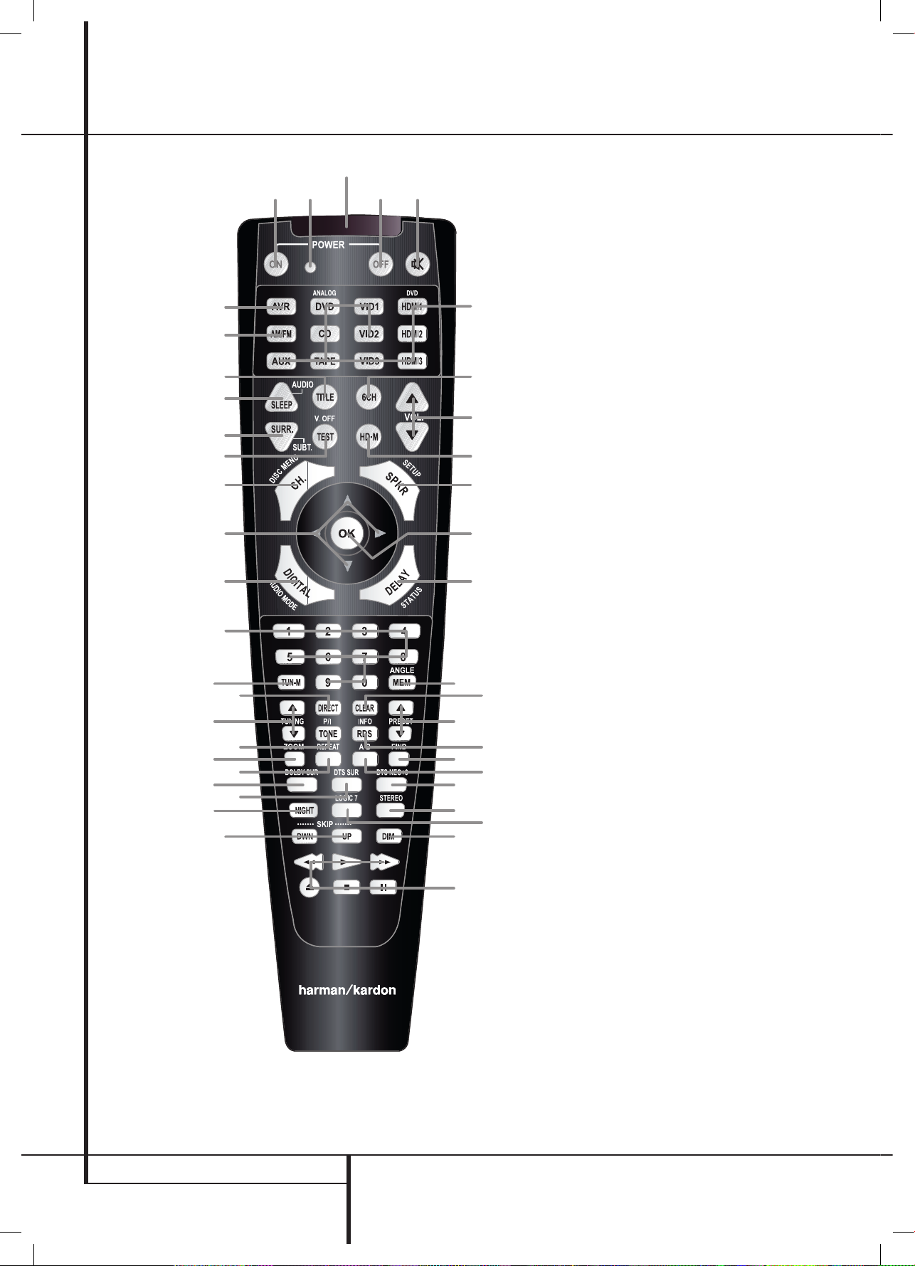
REMOTE CONTROL FUNCTIONS
Remote Control Functions for Receiver and DVD Player System
0
Power On Button
1
Not active
2
IR Transmitter Window
3
Power Off Button
4
Mute
5
Input Selectors
6
6-Channel Direct Input
7
Volume Up/Down
8
HD Mode Selector
9
Speaker Select/Setup
A
OK Button
B
Delay/Status Button
C
Memory/Angle Button
D
Clear Button
E
Preset Up/Down
F
RDS Select
G
Find Button
H
A-B
I
DTS Neo:6 Mode Selector
J
Stereo Mode Selector
K
Logic 7 Selector
L
Dim Button
M
Transport Buttons
N
Skip Up/Down Buttons (DWN)/(UP)
O
Night Mode
P
DTS Digital Mode Selector
Q
Dolby Mode Selector
R
Repeat
S
Zoom Button
T
Tone Mode/Progressive Scan/Interlaced
Button
U
Tuning Up/Down
V
Direct Button
W
Tuner Mode Button
X
Numeric Keys
Y
Digital Select/Audio Mode
Z
Navigation Buttons
a
Channel Select /Disc Menu Button
b
V.OFF/Test Button
c
Surround Mode Selector/Subtitle Button
d
Sleep/Program Up/Audio Select Button
e
Title
f
AM/FM Tuner Select
g
AVR Selector
harman/kardon
DVD 16 and 18 /230V Service Manual
Page 7 of 39
0220CSK - HK AVR-DVD System OM, WORK R2 01.indd 4 12/07/10 14:11:25
Page 8
5
Artwork number: 080-1437
ENGLISH
Remote Control Functions, common for AVR and DVD
REMOTE CONTROL FUNCTIONS
IMPORTANT NOTE: The combined AVR and DVD
remote has some buttons that perform different
functions. If you press the AVR Button
g
, one set
of functions is active, identical to the functions for
buttons CD, Tape, Video 1/2/3. If you press the DVD/
HDMI1 Button
5
, some of the buttons change
their function as indicated above the button itself,
and explained below. Refer to the function table for
an overview of functions in both modes. NOTE that
pressing the HDMI1 and DVD Buttons
5
activate
the alternative commands as seen in the Function List
on page 7.
0
Power On Button: Press this button to turn on
the power to the AVR or the DVD selected by pressing
either the AVR or the DVD/HDMI1 Button
g
or
5
.
1
This indicator is not active.
2
IR Transmitter Window: Point this window
towards the AVR when pressing buttons on the remote
to make certain that infrared commands are properly
received.
3
Power Off Button: Press this button to place
the AVR or a selected device unit in the Standby mode.
If held for more than 3 seconds, both the AVR and the
DVD switch to Standby.
4
Mute: Press this button to momentarily silence
the AVR or TV set being controlled, depending on
which device has been selected.
5
Input Selectors: Pressing one of these buttons
will perform three actions at the same time. First, if
the AVR is not turned on, this will power up the unit.
Next, it will select the source shown on the button as
the input to the AVR. Finally, the DVD/HDMI1 Button
will switch the double-function remote buttons to
their DVD functions. After pressing the DVD/HDMI1
Button, you must press the AVR Selector button
g
again to operate all the AVR’s functions with the
remote. Note that pressing the DVD Button switches
on BOTH the AVR and the DVD, whereas pressing the
AVR Button just switches on the AVR.
6
6-Channel Direct Input: Press this button to
select the component connected to the 6-Channel
Direct Input
N
as the audio. Note that when you
wish to use the Six Channel Direct Input in conjunction
with a video source, you must first select the video
source by pressing one of the Input Selectors
5
.
Then press this button to choose the 6-Channel
Direct Input
N
as the audio source.
7
Volume Up/Down: Press these buttons to raise
or lower the system volume.
8
HD Mode Selector (DVD): When the DVD
player is connected to a video display using the HDMI
Output
A
, the display sends information to the DVD
indicating the highest video resolution it is capable of
handling, and the DVD automatically sets the video
output to match it. Pressing this button allows you
to manually change the output resolution, with your
selection indicated by the Video Output Indicators
O
.
The HD-M button does allow you to force the DVD
player to output video at a resolution that your TV does
not support. If this happens, your TV screen may go
blank or may display "Unsupported Format". If this
occurs:
Wait 10 seconds.
1.
Press the HD-M button, then the Left Navigation 2.
button, then the OK button.
If the video does not recover, repeat steps 1 and 2
again.
9
Speaker Select/Setup: Press this button
to begin the process of configuring the AVR’s Bass
Management System for use with the type of speakers
used in your system. Once the button has been
pressed, use the
KL
buttons Z to select the
channel you wish to set up. Press the OK button
A
and then select the speaker type (see page 14 for more
information.)
For DVD: Press this button to use the DVD’s on-screen
menu system to adjust the player’s configuration
settings. Note that the Info Button
6
must be
pressed to access the DVD’s Information menu to
obtain detailed disc information, and to configure the
playback mode of the disc.
A
OK Button: This button is used to enter settings
into the AVR’s memory. It is also used in the setup
procedures for delay time, speaker configuration and
channel output level adjustment.
B
Delay/Status Button: Press this button to
begin the process for setting delay times and lip sync
delay. (See page 16 for more information).
For DVD: Press while a disc is playing to view banner
display. Use the ARROW buttons to move through
the different features in the Banner Display. When
a symbol is highlighted, press OK on the remote to
select it.
C
Memory/Angle Button: Press this button to
enter a radio station into the AVR’s preset memory.
Two underline indicators will flash at the right side
of the Main Information Display
F
, you then
have five seconds to enter a preset memory location
using the Numeric Keys
X
. (See page 22 for more
information.)
For DVD: Press to access various camera angles on a
DVD (If the DVD contains multiple camera angles) or
to rotate JPEG images.
D
Clear Button: Press this button to clear incorrect
entries when using the remote to directly enter a radio
station’s frequency.
E
Preset Up/Down: When the tuner is in use,
press these buttons to scroll through the stations
programmed into the AVR’s memory. When CD or DVD
is selected using the Input Selector button
5
,
these buttons may function as Slow Fwd/Rev (DVD) or
”+10” (CD).
F
RDS Select/Info (DVD) Button: Press this
button to display the various messages that are part of
the RDS data system of the AVR’s tuner. (See page 22
for more information on RDS).
For DVD: Press for detailed informations on the disc
playing (Video/Audio Bit rate, Movie aspect ratio and
others), and for current player settings made. Note
that the unit doesn’t react on any transport button
as long as the info menu is displayed. Press again to
remove information from screen.
G
Find (DVD): Press this button to search for a
specific location on the disc.
H
A-B (DVD): Press to select section A-B and to
play repeatedly.
I
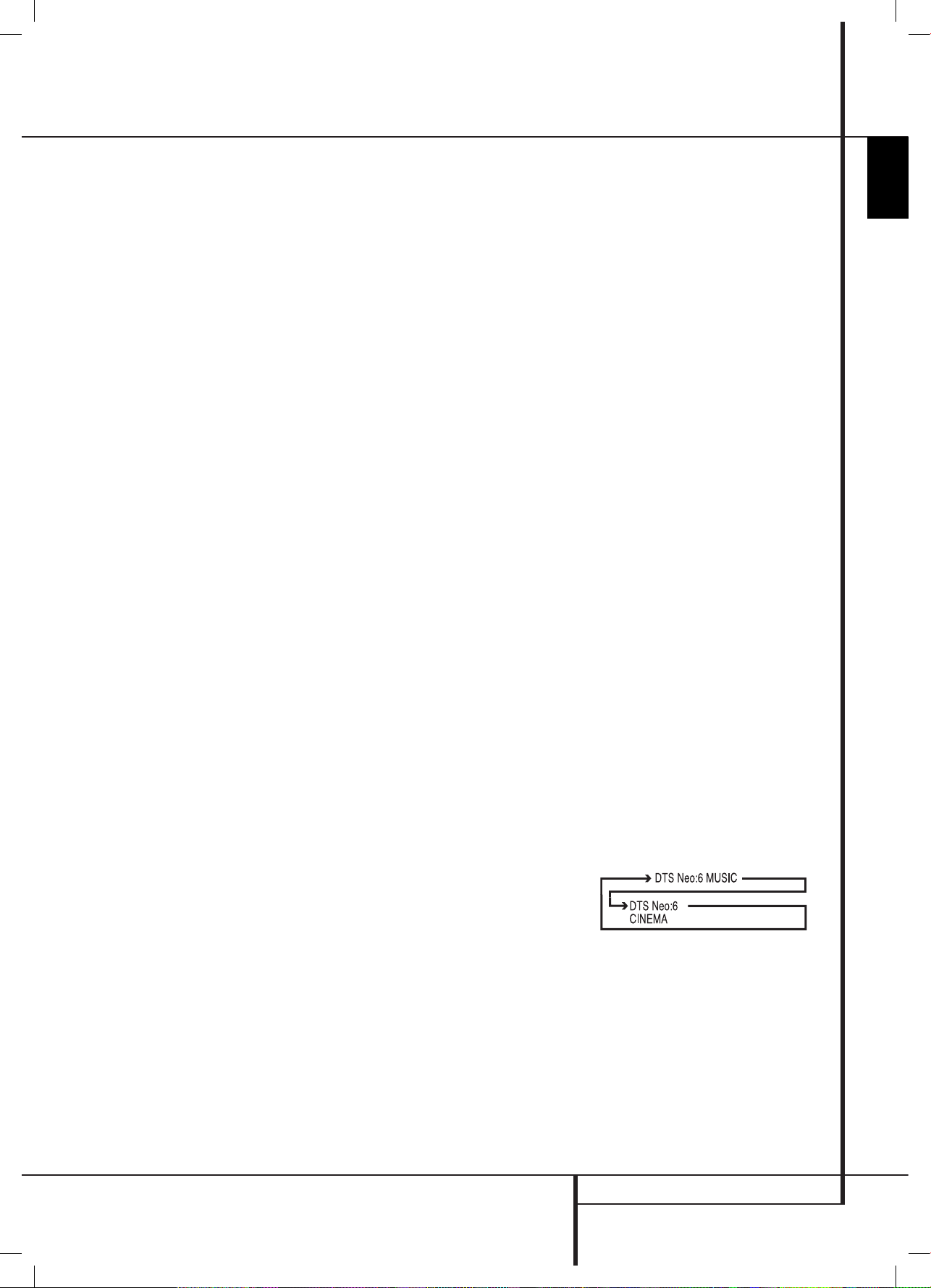
DTS Neo:6 Mode Selector: Pressing this
selector button cycles the AVR through the various DTS
Neo:6 modes, which extract a five-channel surround
field from two-channel program material (from PCM
source or analog input signal). The first press selects
the last DTS Neo:6 surround mode that was in use, and
each subsequent press selects the next mode in the
following order:
harman/kardon
DVD 16 and 18 /230V Service Manual
Page 8
of 39
0220CSK - HK AVR-DVD System OM, WORK R2 01.indd 5 12/07/10 14:11:25
Page 9

6
Artwork number: 080-1437
REMOTE CONTROL FUNCTIONS
Remote Control Functions, common for AVR and DVD
J
Stereo Mode Selector: Press this button to
select a stereo playback mode. When the button
is pressed so that
DSp SURR OFF
appears in
the Main Information Display
F
, the AVR will
operate in a bypass mode with true fully analog,
two-channel left/right stereo mode with no surround
processing or bass management as opposed to other
modes where digital processing is used. When the
button is pressed so that
SURROUND OFF
appears
in the Main Information Display
F
, you may
enjoy a two-channel presentation of the sound along
with the benefits of bass management. When the
button is pressed so that
5 CH STEREO
appears,
the stereo signal is routed to all five speakers, if
installed.(See page 15 for more information on stereo
playback modes).
K
Logic 7 Selector: Press this button to select one
of the available Logic 7 surround modes. (See page 19
for the available Logic 7 options).
L
Dim Button: Press this button to activate the
Dimmer function, which reduces the brightness of
the front panel display, or turn it off entirely. The first
press of the button shows the default state, which
is full brightness by indicating
VFD FUll
in the
Main Information Display
F
. Press the button
again within five seconds to reduce the brightness by
50%, as indicated by
VFD HalF
. Press the button
again within five seconds and the main display will go
completely dark. Note that this setting is temporary;
the display will always return to full brightness when
the AVR is turned on. In addition,both the Power
Indicator
2
and the blue accent lighting inside the
volume control will always remain at full brightness
regardless of the setting. This is to remind you that the
AVR is still turned on.
M
Transport Buttons: These buttons operate the
DVD player.
N
Skip Up/Down Buttons (DVD):
(DWN): Press to go to beginning of current track. Press
again quickly to go to beginning of previous track.
After pressing the PAUSE button, each press of this
button will move the image in reverse frame by frame.
(UP): Press to go to beginning of next track. After
pressing the PAUSE
button, each press of this button
will move the image forwards frame by frame.
O
Night Mode: Press this button to activate the
Night mode. This mode is available only with Dolby
Digital encoded digital sources, and it preserves dialog
(center channel) intelligibilty at low volume levels
(See page 16
for more information).
P
DTS Digital Mode Selector: When a DTS
source is in use the AVR will select the appropriate
mode automatically and no other mode will be
available. Pressing this button will display the mode
currently selected by the AVR´s decoder, depending on
the surround material played and the speaker setting.
Q
Dolby Mode Selector: This button is used to
select one of the available Dolby Surround processing
modes. Each press of this button will select one of
the Dolby Pro Logic II modes, Dolby 3 Stereo or Dolby
Digital. Note that the Dolby Digital mode is only
available with a digital input selected and the other
modes only as long as a Dolby Digital source is not
playing.
R
Repeat (DVD): Each press of this button
changes the playback mode to repeat a chapter or
track or the entire disc. A repeat icon will appear in the
upper right corner of the screen indicating the current
repeat mode. If the Player Information Screen is active,
the changes will be displayed on screen.
S
Zoom Button: When a DVD is playing, press this
button to zoom the picture so that it is enlarged. There
are 4 steps to the zoom function, each progressively
larger. Press through each of the zoom stages to return
to a normal picture.
T
Tone Mode/Progressive Scan/Interlaced
Button: Pressing this button enables or disables the
Bass and Treble tone controls. When the button is
pressed so that the words
TONE IN
appear in the
Main Information Display
F
, the settings of
the Bass and Treble controls will affect the output
signals. When the button is pressed so that the words
TONE OUT
appear in the Main Information
Display
F
, the output signal will be “flat,” without
any bass or treble alteration.
For DVD: Press this button to change the resolution
of the Component Video Output between standard
definition and progressive definition (PAL interlaced
and PAL progressive; NTSC interlaced and NTSC
progressive).
The new setting will become effective after quitting
the Setup menu.
U
Tuning Up/Down: When the tuner is in use,
these buttons will tune up or down through the
selected frequency band. If the Tuner Mode
button
W
has been pressed or the Band button 8 on the
front panel was held pressed so that
aUTO
appears
in the Main Information Display
F
, pressing
either of the buttons will cause the tuner to seek the
next station with acceptable signal strength for quality
reception. When the
maNUal
appears in the Main
Information Display
F
, pressing these buttons
will tune stations in single-step increments. (See page
22 for more information).
V
Direct Button: Press this button when the
tuner is in use to start the sequence for direct entry
of a station’s frequency. After pressing the button
simply press the proper Numeric Keys
X
to select
a station (See page 22 for more information on the
tuner).
W
Tuner Mode: Press this button when the tuner is
in use to select between automatic tuning and manual
tuning. When the button is pressed so
maNUal
appears in the Main Information Display
F
,
pressing the Tuning buttons
U7
will move the
frequency up or down in single-step increments.
When the FM band is in use and
aUTO
appears in
the Main Information Display
F
, pressing this
button will change to monaural reception making
even week stations audible. (See page 22 for more
information.)
X
Numeric Keys: These buttons serve as a ten-
button numeric keypad to enter tuner preset positions.
For DVD play you may enter track numbers directly,
followed by OK to go to the track.
Y
Digital Select/Audio Mode: Press this button
to assign one of the digital inputs
4G9L to a
source. (See page 12 for more information on using
digital inputs.) Audio Mode: When operating the
DVD, press this button to switch between Audio
Modes.
Z
Navigation Buttons: These buttons are used to
increase or decrease output levels when configuring
the unit, to select speaker configuration or to select the
digital inputs.
a
Channel Select /Disc Menu Button: This
button is used to start the process of setting the AVR’s
output levels with an external source. Once this button
is pressed, use the
KL
buttons Z to select the
channel being adjusted, then press the OK button
A
, followed by the KL buttons again, to change
the level setting. (See page 21 for more information.)
DVD Disc Menu: Displays the actual DVD Disc Menu
on the TV screen in play mode. When playing discs
with JPEG images, pressing this button will access the
thumbnails.
b
V.OFF/Test Button: Press to turn off video
output for improved performance from audio-only
discs. Press again to restore video output.
Tone: Press this button to begin the sequence used
to calibrate the AVR’s output levels. (See page 16 for
more information on calibrating the AVR).
harman/kardon
DVD 16 and 18 /230V Service Manual
Page 9
of 39
0220CSK - HK AVR-DVD System OM, WORK R2 01.indd 6 12/07/10 14:11:25
Page 10
7
Artwork number: 080-1437
ENGLISH
Remote Control Functions, common for AVR and DVD
REMOTE CONTROL FUNCTIONS
c
Surround Mode Selector/Subtitle Button:
Press this button repeatedly to select an available
surround mode.
When a DVD is playing, press to select a subtitle
language or to turn subtitles off.
Note: Due to the variations in how DVD discs are
authored, the subtitle languages selected with the
Subtitle Button may not accurately reflect the actual
languages available on the disc. It is recommended
that subtitles be selected using the disc’s menu.
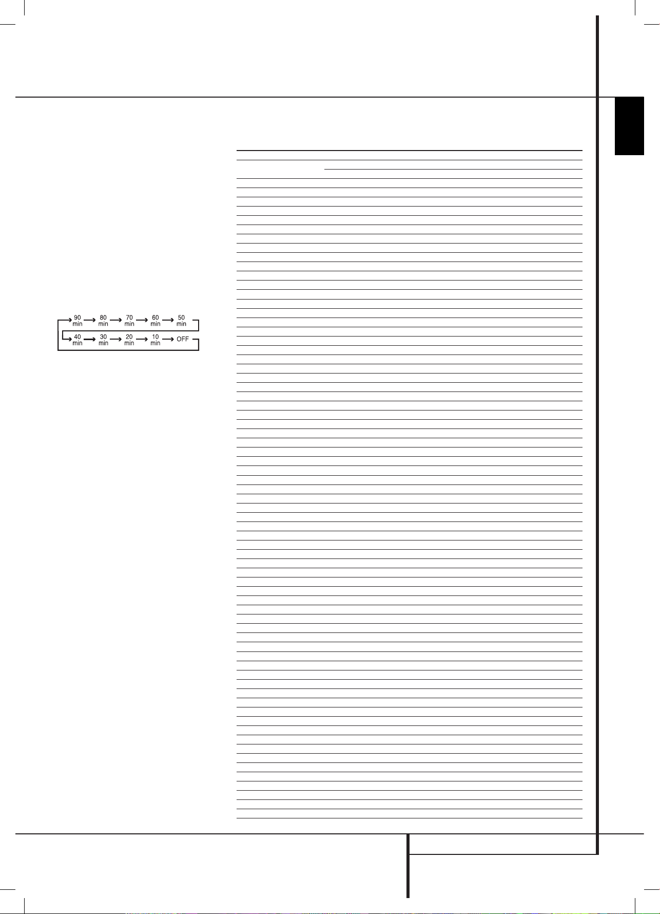
d
Sleep/Program Up>/Audio Select Button:
Press this button to place the unit in the Sleep mode.
After the time shown in the display, the AVR will
automatically go into the Standby mode. Each press
of the button changes the time until turn-off in the
following order:
Hold the button pressed for two seconds to turn off the
Sleep mode setting.
Note that this button is also used to change channels
on your TV, VCR and SAT receiver when selected.
DVD: Press to access various audio languages on a DVD
(If the DVD contains multiple audio streams).
e
Title: When a disc is playing, press to make the
DVD-player go back to the first section of the disc. If
you are playing a DVD-Audio disc, pressing this button
returns you to the Disc Menu with most DVD-A discs.
f
AM/FM Tuner Select: Press this button to select
the AVR’s tuner as the listening choice. Pressing this
button when the tuner is in use will select between
the AM and FM bands.
g
AVR Selector: Pressing this button will switch
the remote so that it will operate the AVR’s functions.
If the AVR is in the Standby mode, it will also turn the
AVR on.
Function List
Button Name
HK AVR Remote Command
AVR/TAPE/CD/AUX/VID1/VID2/VID3/HDMI2/HDMI3
HK DVD Remote Command
DVD/HDMI1
Power ON Power On Power On
Power OFF Power Off (press and release) Power Off (press and release)
Power Off (press and hold) Power Off (press and hold)
Mute Mute Mute(AVR)
AVR AVR Power On AVR(AVR)
DVD DVD DVD(AVR)
VID1 VID 1 VID 1(AVR)
HDMI1 HDMI 1 HDMI 1(AVR)
AM/FM AM/FM AM/FM(AVR)
CD CD CD(AVR)
VID2 VID 2 VID 2(AVR)
HDMI2 HDMI 2 HDMI 2(AVR)
AUX AU X AUX(AVR)
TAPE TAPE TAPE(AVR)
VID3 VID 3 VID 3(AVR)
HDMI3 HDMI 3 HDMI 3(AVR)
SLEEP / AUDIO Sleep Audio
TITLE Title
6CH 6CH 6CH(AVR)
VOL Up Vol Up Vol Up(AVR)
SURR. / SUBT. Surround Mode Subtitle
TEST / V.OFF Test Tone Video Off
HD-M HD Mode
VOL Down Vol Down Vol Down(AVR)
CH. / DISC MENU Channel Select Disc Menu
SPKR / SETUP Speaker Select Setup
Level+/Up Level+/Up Up
Left
M Left Left
OK SET Enter
Right
N Right Right
Level-/Down Level-/Down Down
DIGITAL / AUDIO MODE Digital S elect Audio Mode
DELAY / STATUS Delay Status
1 1 1
2 2 2
3 3 3
4 4 4
5 5 5
6 6 6
7 7 7
8 8 8
TUN-M Tuner Mode
9 9 9
0 0 0
MEM / ANGLE Memory Angle
TUNING Up Tuning Up
DIRECT Direct Tuning
CLEAR Clear Clear
PRESET Up Preset Up Slow Up
TUNING Down Tuning Down
TONE / P/I Tone Mode P/I
RDS / INFO RDS Info
PRESET Down Preset Down Slow Down
ZOOM Zoom
REPEAT Repeat Play
A-B A-B Repeat Play
FIND Search
DOLBY SUR Dolby Surround Dolby Surround(AVR)
DTS SUR DTS Surround DTS Surround(AVR)
DTS NEO:6 DTS NEO:6 DTS NEO:6(AVR)
NIGHT Night Mode Night(AVR)
LOGIC 7 Logic7 Logic7(AVR)
STEREO Stereo Stereo(AVR)
SKIP DOWN Skip Down(DVD) Skip Down
SKIP UP Skip Up(DVD) Skip Up
DIM Dimmer Dimmer
Rew(
G
) Rew(DVD) Rew
Play(
B
) Play(DVD) Play
FF(
H
) FF(DVD) FF
Open/Close Open/Close(DVD) Open/Close
Stop Stop(DVD) Stop
Pause Pause(DVD) Pause
harman/kardon
DVD 16 and 18 /230V Service Manual
Page 10 of 39
0220CSK - HK AVR-DVD System OM, WORK R2 01.indd 7 12/07/10 14:11:25
Page 11
11
Artwork number: 080-1437
ENGLISH
Rear Panel Connections
REAR PANEL CONNECTIONS
B
Video Monitor Output: Connect these jacks to
the composite input of a TV monitor or video projector
to view the output of any video source selected by the
receiver’s video switcher.
C
HDMI Inputs: Connect the HDMI output of video
sources such as a DVD player, set-top box or HDTV
tuner to either of these jacks.
D
HDMI Output: Connect this jack to the HDMI
input on a compatible HDMI-equipped video display.
E
Monitor Component Video Outputs: Connect
these outputs to the component video inputs of a
video projector or monitor. When a source connected
to one of the two Component Video Inputs
8F
is selected the signal will be sent to these jacks.
F
Video 2 Component Video Inputs: Connect
the Y/Pr/Pb component video outputs of a DVD player
to these jacks.
Note: All component inputs/outputs can be used for
RGB signals too, in the same way as described for the
Y/Pr/Pb signals, then connected to the jacks with the
corresponding color.
RGB connection is not possible if the source outputs a
separate sync signal (see page 13).
G
AC Power Cord: Connect the AC plug to an
unswitched AC wall output.
H
DVD Video Inputs: Connect these jacks to the
composite output jacks on a DVD player or other video
source.
I
Video 1 Video Outputs: Connect these jacks to
the RECORD/INPUT composite jack on a VCR.
J
Video 2 Audio Inputs: Connect these jacks to the
PLAY/OUT audio jacks on a VCR or other video source.
K
Video 2 Video Inputs: Connect these jacks to the
PLAY/OUT composite jacks on a second VCR or other
video source.
L
Optical Digital Inputs: Connect the optical
digital output from a DVD player, HDTV receiver, LD
player, MD player or CD player to these jacks. The
signal may be either a Dolby Digital signal, a DTS
signal or a standard PCM digital source.
M
Video 1 Video Inputs: Connect these jacks to
the PLAY/OUT composite jacks on a TV or other video
source.
N
6-Channel Direct Inputs: These jacks are used
for connection to source devices such as DVD-Audio or
SACD players with discrete analog outputs.
O
Digital Audio Output: Connect this jack to the
matching digital input connector on a digital recorder.
PQS
Front/Center Speaker Outputs: Connect
these outputs to the matching + or – terminals on
your front/center speakers. When making speaker
connections, always make certain to maintain correct
polarity by connecting the red (+) terminals on the
AVR to the red (+) terminals on the speaker and
the black (–) terminals on the AVR to the black (–)
terminals on the speakers. (See page 14 for more
information on speaker polarity.)
RT
Surround Speaker Outputs: Connect these
outputs to the matching + or – terminals on your left
and right surround speakers. When making speaker
connections always make certain to maintain correct
polarity by connecting the red (+) terminals on the
AVR to the red (+) terminals on the speakers and
the black (–) terminals on the AVR to the black (–)
terminals on the speakers. See page 14 for more
information on speaker polarity.
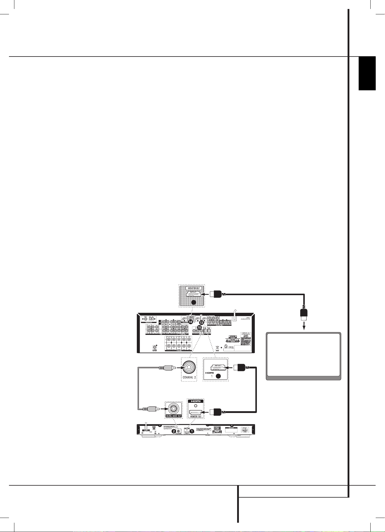
AVR/DVD System Connections
AVR/DVD System Connection Instructions:
Connect your system like this, using the HDMI cable
and the digital audio cable included with the DVD
player:
Connect the DVD player's HDMI output
1.
0
to the
receiver's HDMI 1 input
C
. NOTE: Do not use any
other input for this connection.
Connect the DVD player's Digital Audio Out
2.
1
to the
receiver's Coaxial 2 digital audio input 9. NOTE:
Do not use any other input for this connection.
Connect the receiver's HDMI Monitor Out
3.
D
to your
TV's HDMI input connector.
IMPORTANT
: You MUST connect the DVD Player's
Coaxial Digital Output to the AVR Receiver's Coaxial
Digital Input 2 to hear Dolby Digital and DTS surround
sound through your new AVR/DVD system.
AVR
To HDMI In
Digital Audio Cable
(supplied with
DVD player)
HDMI Cable
(supplied with
DVD player)
HDMI Cable (not supplied)
DVD Player
TV
harman/kardon
DVD 16 and 18 /230V Service Manual
Page 11 of 39
0220CSK - HK AVR-DVD System OM, WORK R2 01.indd 11 12/07/10 14:11:27
Page 12
27
Artwork number: 080-1437
ENGLISH
High quality video
High Definition Multimedia Interface (HDMI) for a •
single wire, digital connection to your HD-Ready
screen.
Advanced sophisticated 10-bit MPEG-2 video
•
decoding circuits.
P
• ure PAL with NTSC disc due to true NTSC/PAL
conversion.
Dual-layer compatibility for extended play DVD
• .
P
• layback of JPEG image files
High quality digital audio
B • y connecting a DTS or a Dolby Digital decoder,
you can enjoy high quality 5.1 digital surround
sound from DTS or Dolby Digital discs.
With linear PCM audio at 16-24 bits and
•
44-96 kHz (also on digital output, see table
• page
30), audio quality exceeding that of CD becomes
possible.
Coaxial digital audio output.
•
Many convenient features
On-Screen Menu for disc information or player •
information.
Subtitles may be displayed in one of numerous
•
languages*.
The multi-angle function allows you to choose
•
the viewing angle of scenes which were shot from
a number of different angles (Limited to DVD’s
recorded with multiple camera angles.)
Multiple options for dialog language and
•
soundtrack selection (limited to DVD’s recorded
with multiple dialog languages or soundtracks).
4-
• step Zoom during play and pause.
Backlit, ergonomically designed remote control • .
* The number of languages recorded depends on the
software.
Compatible with CD as well as DVD
The DVD player will play any conventional Audio CD
or recordable (CD-R) or erasable CD (CD-RW), MP3 or
any DVD/Video disc with the region code 0 or 2.
Disc formats supported by this player
The unit can play the following disc formats (8 cm and
12 cm size):
D
• VD
DVD-R
•
DVD-RW
•
DVD+R
•
DVD+RW
•
CD
•
CD-R
•
CD-R
• W
NOTE: Due to differences in the format of certain
discs, it is possible that some discs may include a
mix of features that are not compatible with the DVD
player. Similarly, although the DVD player is capable
of a wide range of features, not all discs include every
capability of the DVD system. For example, although
the DVD player is compatible with multi-angle discs,
that feature is only possible when the disc is specially
encoded for multi pleangle play. In addition, the DVD
player is capable of playing back both Dolby Digital
and DTS soundtracks, but the number and types of
tracks available will vary from disc to disc. To make
cer tain that a specific feature or soundtrack option is
available, please check the options noted on the disc
jacket.
Playback capability for CD-R, CD-RW
■ , JPEG, MP3,
DivX, DVD-R, DVD+R, DVD-RW and DVD+RW
discs may vary due to variations in the quality of
the disc and the recorder used to create the disc.
The DVD player is compatible with most discs
■
recorded with files encoded using MP3 as well as
JPEG still images. However, note that variations
in the encoder or codec used and the bit rate
of the encoding may affect the DVD player's
ability to play back a specific disc. As a result,
we cannot guarantee complete compatibility
with all encoders and versions of the codecs. For
best results, we recommend that MP3 files be
encoded at bit rates ranging between 32kbps and
320kbps. JPEG files should contain no more than
5 megapixels, and the file size should be no larger
than 5Mb.
The DVD player will NOT play the
following:
DVD discs with a Region Code other than 2 •
DVD-ROM data discs
•
DVD-RAM discs
•
DVD-Audio discs
•
SACD discs
•
CD-I discs
•
CD-G discs
•
SVCD discs
•
Kodak Photo CD™ discs (Kodak Picture CD discs,
•
available to consumers, may be viewed using the
DVD).
Discs intended for use in video game consoles
•
Discs recorded in the “VR” mode or at any speed
•
other than “SP”
High-definition optical discs such as WMVHD,
•
HD-DVD and Blu-ray
Packing List
1 Harman Kardon DVD Player
1 Coaxial digital audio cable
1 HDMI cable
Features
FEATURES
NOTE: This player is designed and manufactured
for compatibility with Region Management
Information that is encoded on most DVD discs.
This player is designed only for playback of discs
with Region Code 2, or for discs that do not contain
Region Code infor mation. If there is any other
Region Code on a disc, that disc will not play on the
DVD player.
CLASS 1
LASER PRODUCT
harman/kardon
DVD 16 and 18 /230V Service Manual
Page 12 of 39
0220CSK - HK AVR-DVD System OM, WORK R2 01.indd 27 12/07/10 14:11:30
Page 13

28
Artwork number: 080-1437
�
2
134
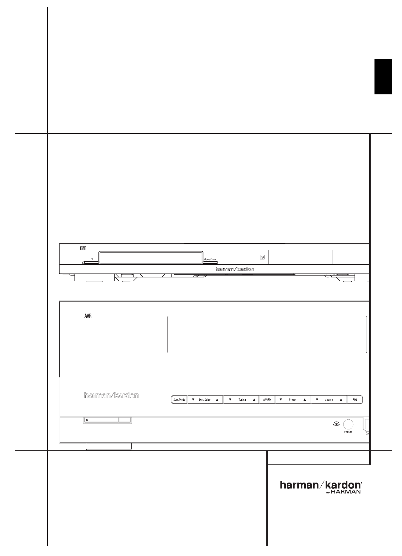
0
Power Button: Press the button once to turn
the DVD player on, press it again to put the
player in the Standby mode.
1
Disc Drawer: Insert a compatible disc into
the drawer. The DVD player will accept 5-inch
(12cm) and 3-inch (8cm) discs.
2
Open/Close Button: Press this button to open
and close the disc drawer. Before pressing this
button, make sure no objects are blocking the
disc drawer.
3
IR Remote Receiver: This receives infrared
signals from the remote control. Aim the remote
at this area and do not block or cover it.
4
Information Display: This 7-character
alphanumeric display delivers messages and
status indications to help you operate the DVD
player.
FRONT PANEL CONTROLS
Front Panel Controls
0
Power Button
1
Disc Drawer
2
Open/Close Button
3
IR Remote Receiver
4
Information Display
harman/kardon
DVD 16 and 18 /230V Service Manual
Page 13 of 39
0220CSK - HK AVR-DVD System OM, WORK R2 01.indd 28 12/07/10 14:11:30
Page 14

29
Artwork number: 080-1437
ENGLISH
Rear Panel Connections
REAR PANEL CONNECTIONS
0
HDMI Output
1
Coaxial Digital Output
2
AC Power Cord
0
HDMI Output: Connect this output to an HDMI
input on the receiver or video display for the
highest-quality uncompressed digital audio
and video available. Even if your receiver is not
capable of processing audio in the HDMI format,
you may still experience the superb reproduction
of HDMI video.
The AVR Receiver in your AVR/DVD system can switch
between three HDMI inputs and send the video signal
to your screen from its HDMI Output. No surround
sound decoding takes place in the Receiver from
HDMI inputs, so no surround sound will be heard if
only HDMI is connected. You MUST connect the DVD
Player's Coaxial Digital Output to the AVR Receiver's
Coaxial Digital Input 2 to hear Dolby Digital and DTS
surround sound through your new AVR/DVD system.
If your video display has a DVI input, you may use
an optional HDMI-to-DVI cable or adapter for the
connection to the display.
In all cases, the video display must be HDCP-compliant
in order to use the HDMI output.
For best results, we do not recommend HDMI
connections in excess of 3m (10 ft).
1
Coaxial Digital Output: Connect this jack to
the coaxial digital input of an A/V receiver or
surround processor for Dolby Digital, DTS or PCM
audio playback.
The AVR Receiver in your AVR/DVD system has two
coaxial digital inputs. Be sure to connect the DVD
player’s Coaxial Digital Output to the Receiver’s Coaxial
Digital Input 2. You MUST connect the DVD Player's
Coaxial Digital Output to the AVR Receiver's Coaxial
Digital Input 2 to hear Dolby Digital and DTS surround
sound through your new AVR/DVD system.
Note: The coaxial digital output should only be
connected to a digital input. Even though it is the
same RCA-type connector as standard analog audio
connections, DO NOT connect it to a conventional
analog input jack.
2
AC Power Cord: Connect this plug to an AC
outlet. If the outlet is controlled by a switch,
make certain that it is in the ON position.
Note
: You’ll find more details about all Audio/Video
connections under Setup and Connections on the
following pages.
harman/kardon
DVD 16 and 18 /230V Service Manual
Page 14 of 39
0220CSK - HK AVR-DVD System OM, WORK R2 01.indd 29 12/07/10 14:11:30
Page 15

30
Artwork number: 080-1437
SETUP AND CONNECTIONS
Setup and Connections
Before connecting your DVD player,
please:
Ensure that the power switch of this unit and other ■
equipment to be connected is set to off before
commencing connection.
Do not block ventilation holes of any of the
■
equipment and arrange them so that air can
circulate freely.
Read through the instructions before connecting
■
other equipment.
Ensure that you observe the color coding when
■
connecting audio and video cables.
With a single cable connection between components,
HDMI is able to deliver uncompressed high-definition
digital video and digital audio programming. Please
note that the AVR Receiver in this system does not
process audio through HDMI. Therefore, a separate
digital audio connection must be established between
the DVD player and AVR.
Note: If your video display has a DVI input, you may
use an optional HDMI-to-DVI cable or adapter for
the connection to the display. In all cases, the video
display must be HDCP-compliant in order to use the
HDMI output.
If you're connecting to a different audio/video receiver
that processes audio through HDMI, connect the DVD
player's HDMI output to one of the receiver's HDMI
inputs. No other connections are required between the
DVD player and receiver.
If you're connecting to a different audio/video receiver
that does not process audio through HDMI, connect
the DVD player's HDMI output to one of the receiver's
HDMI inputs (for video only), and connect the DVD
player's Coaxial Digital Audio Output to one of the
receiver's coaxial audio inputs. Refer to the receiver's
owner's manual for instructions about setting up its
audio and video inputs.
Digital Audio Connections
Audio output from the DVD player's
coaxial digital audio output connector
Disc
Sound recording
format
Coaxial digital
audio output
DVD Dolby Digital Dolby Digital bitstream
(2-5.1ch) or PCM
(2ch, 48kHz, 16-bit)
Linear PCM
(48/96kHz,
16/20/24-bit)
Linear PCM (2ch)
(48/96kHz,
16/20/24-bit)
DTS Bitstream or no output*
MPEG (2.0) MPEG bitstream (2ch) or
linear PCM (2ch, 48kHz)
CD Linear PCM Linear PCM (44.1kHz
sampling)
MP3
MPEG-1
Audio Layer 3)
Linear PCM
(44.1–48kHz, depending
on source, if digital
output format selected
as “Bitstream”).
(48kHz if digital
output format
selected as “PCM”)
* Digital Format must be selected as “ORIGINAL“
or ”PCM” respectively in Menu
For your reference:
Dolby Digital is a digital audio compression ■
technique developed by the Dolby Laboratories
Licensing Corporation, supporting 5.1-channel
surround sound, as well as stereo (2-channel)
sound, this technique enables a large quantity of
sound data to be efficiently recorded on a disc.
Linear PCM is a signal recording format used in
■
CDs. While CDs are recorded in 44.1kHz/16 bit,
DVDs are recorded in 48kHz/16 bit up to 96kHz/24
bit.
The
■ DVD player is designed to digitally output
96kHz-PCM audio with a 96kHz sampling rate.
However, some 96kHz DVD's may include copy
protection codes that do not permit digital output.
In this case, use the "Down Sample" setup menu
to switch the sampling rate to 48kHz.
Caution for the coaxial digital audio
outputs:
When connecting an amplifier (with coaxial digital ■
input) which does not contain a Dolby Digital
or DTS decoder, be sure to select ”PCM” as initial
setting in the ”Digital Out” setup menu.
Otherwise, any attempt to play a DVD may cause
such a high level of noise that it may be harmful to
your ears and damage your speakers.
CD’s can be played as they would normally be
■
played.
Note:
Some first generation DTS decoders which do not
■
support DVD-DTS interface may not work properly
with the DVD player.
Dolby Digital, DTS and PCM signals are passed
■
through the HDMI Output
0
but are not
processed in the AVR Receiver in your AVR/DVD
system. Connect the Coaxial Digital Audio Output
separately in addition to the HDMI connection to
get sound from your system Receiver.
Dolby Digital and DTS
Both Dolby Digital and DTS are audio formats used to
record 5.1-channel audio signals onto a film’s digital
soundtrack. Both of these formats provide six separate
channels: left, right, center, left rear, right rear, and
common subwoofer.
Remember, that Dolby Digital or DTS will only play
5.1-channel sound if you’ve connected the coaxial
output of the DVD player to a DTS or Dolby Digital
receiver or decoder and if the disc was recorded in the
Dolby Digital or DTS format.
harman/kardon
DVD 16 and 18 /230V Service Manual
Page 15 of 39
0220CSK - HK AVR-DVD System OM, WORK R2 01.indd 30 12/07/10 14:11:30
Page 16

38
Artwork number: 080-1437
TROUBLESHOOTING GUIDE
Troubleshooting Guide
SYMPTOM CAUSE SOLUTION
Unit does not turn on No AC Power
• Check AC power plug and make certain any switched outlet is turned on. •
Disc does not play Disc loaded improperly
• Load disc label-side up; align the disc with the guides and place it in its •
proper position.
Incorrect disc type
• Check to see that disc is CD, CD-R, CD-RW, MP3, JPEG, DVD-R, DVD-RW, •
DVD+R, DVD+RW (standard conforming), or DVD-Video; other types will
not play.
Invalid Region Code
• Use Region 2 or Open Region (0) disc only. •
Rating is above parental preset
• Enter password to override or change rating settings. •
No picture Intermittent connections
• Check all video connections. •
Wrong input
• Check input selection of TV or receiver. •
• HDMI Output A is connected to a video
display that is not HDCP-compliant.
The • HDMI Output A may not be used with video displays that are not
HDCP-compliant. Unplug the cable and select another audio and video
connection (see page 30).
No sound Intermittent connections
• Check all audio connections. •
Incorrect digital audio selection
• Check digital audio settings. •
DVD disc is in fast or slow mode
• There is no audio playback on DVD discs during fast or slow modes. •
Picture is distorted or jumps during fast
forward or reverse play
MPEG-2 decoding
• It is a normal artifact of DVD playback for pictures to jump or show some •
distortion during rapid play.
Some remote buttons do not operate
during DVD play; "
pROHIBITED
"
symbol appears (see below)
Function not permitted at this time
• With most discs, some functions are not permitted at certain times (e.g., •
Track Skip) or at all (e.g., direct audio track selection).
The OSD menu is in a foreign language Incorrect OSD language
• Change the display language selection. •
"
pROHIBITED
" appears Requested function not available at this time • Certain functions may be disabled by the DVD itself during passages of a •
disc.
Picture is displayed in the wrong aspect
ratio
Incorrect match of aspect ratio settingsto disc
• Change aspect ratio settings. •
Remote control inoperative Weak batteries
• Change all batteries. •
Sensor is blocked
• Clear path to sensor or use optional outboard remote sensor. •
Disc will not copy to VCR Copy protection
• Many DVDs are encoded with copy protection to prevent copying to VCR. •
Password not accepted. Incorrect password being used or password
•
has been forgotten.
Stop play of disc. Press and hold the • Clear Button D until the display
blinks. This resets the password and all settings to their defaults.
harman/kardon
DVD 16 and 18 /230V Service Manual
Page 16 of 39
0220CSK - HK AVR-DVD System OM, WORK R2 01.indd 38 12/07/10 14:11:32
Page 17

39
Artwork number: 080-1437
ENGLISH
Technical Specifications for DVD Player
TECHNICAL SPECIFICATIONS
Applicable Disc: Disc formats: 5 inch (12 cm) or 3 inch (8 cm) DVD Video, Standard conforming DVD+RW, DVD+R, DVD-R,
DVD-RW, DivX, CD, CD-R, MP3, JPEG or CD-RW discs,
Regio code: DVD Movie disc with Code 2 or 0 only.
DVD-Layers: Single Side/Single Layer, Single Side/Dual Layer, Dual Side/Single Layer, Dual Side/Dual Layer
Audio formats: Linear PCM, MPEG, Dolby Digital or DTS Audio discs.
Still-image format: JPEG
Video Signal System: PAL/NTSC
HDMI™ Output: Video: 576p, 720p, 1080i, 1080p
HDMI Version 1.3-compliant
Wow & Flutter:
Below Measurable Limits
AC Power: 100 - 240V/50 ~ 60Hz
Power Consumption:
1 Watt (Standby)/13 Watts (Max)
Dimensions (WxHxD): 440mm x 206mm x 49mm
Weight:
1.65 kg
Depth measurement includes knobs and connectors.
Height measurement includes feet and chassis.
Features, specifications and appearance are subject to change without notice.
Harman Consumer, Inc.
8500 Baloba Blvd., Northridge, CA 91329 USA
© 2010 Harman International Industries, Incorporated. All rights reserved.
Harman Kardon is a registered trademark of Harman International Industries, Incorporated, registered in the United States and/or other countries.
Manufactured under license from Dolby Laboratories. Dolby, Pro Logic and the double-D symbol are registered trademarks of Dolby Laboratories.
Manufactured under license under U.S. Patent # 5,451,942 & other U.S. and worldwide patents issued & pending. DTS and DTS-ES are registered trademarks and DTS Advanced Digital Out and the
DTS logo are trademarks of DTS, Inc.
Blu-Ray Disc is a trademark of the Blu-Ray Disc Association.
HDMI, the HDMI logo and High-Definition Multimedia Interface are trademarks or registered trademarks of HDMI Licensing LLC.
This product incorporates copyright protection technology that is protected by U.S. patents and other intellectual property rights. Use of this copyright protection technology must be authorized by
Rovi Corporation and is intended for home and other limited viewing uses only unless otherwise authorized by Rovi Corporation. Reverse engineering or disassembly is prohibited.
harman/kardon
DVD 16 and 18 /230V Service Manual
Page 17 of 39
0220CSK - HK AVR-DVD System OM, WORK R2 01.indd 39 12/07/10 14:11:32
Page 18

4-1
BIN FILE: HM_EU16.BIN
harman/kardon
DVD 16 and 18 /230V Service Manual
Page 18 of 39
Software check and upgrade
Preparation to upgrade software
1. Start the CD burning software;
2. Then copy the Bin file (HM_EU16bin) into it;
3. Burn the data onto the blank CD. 1. Power on the set and open the tray door.
A. Procedure for software upgrade
-Upgrade software via Disc
1. Power on the set and insert the prepared Upgrade SC:135: XXXXX
CDR. F/W ID: XXXXX
2. The set will start reading and response with the CHIP ID: XXXXX
following display on TV screen: ERGION: X
3. Press <YES> button to confirm, then screen will
display as below, and the tray will automatically open,
then take the upgrade CD out.
B. Read out the software versions to confirm upgrading
2. Press press <7><7><7><7> button on the reomote control.
3. Then need choose "VERSION" item, the version informations
will display as following:
BIN FILE: HM EU16.BIN
VERSION: HM_EU16 VXX
Caution: The set must not be power off during
upgrading, otherwise the Main board will be
damaged entirely.
4. Please wait for a moment, the tray will close and set
restarts automatically when upgrading completed.
Page 19
No display on VFD, and buttons do not work
harman/kardon
DVD 16 and 18 /230V Service Manual
Page 19 of 39
No display on VFD, and
buttons do not work
Yes
5-1
Trouble shooting chart
Check every supply
voltage on main board is
normal
Yes
Check5V,+12V,-24V
voltage on the power
and front board
Yes
Check the front board
signals CS CLK DATA
No
No
Refer to Power supply board part
Fix the connection XS2 on front board
and CON2 on power board
Check the main board U1’s pin 28,
No
29, 31 arrive the front board U301’s
pin5, 6, 8, 9 connect condition
Yes
1. Check whether bad solder exists
on the front board U301 and pins
of VFD
2.Check whether the circuit
connected to SW1 ˈ SW301 is
broken.
Yes
Replace U301 or VFD
No
Correct connection
Page 20

Remote control does not work
harman/kardon
DVD 16 and 18 /230V Service Manual
Page 20 of 39
Remote control
does not work
Go
5-2
Trouble shooting chart
Check whether the remote
controller’s battery is
exhausted or not.
No
Check the REM301
power supply is OK,
Yes
REM301.3 is about 5V
Yes
Yes
No
Replace the battery for remote
controller
Check the VCC net on front board
Check the IR signal
output of REM301.1
Yes
Replace REM301
No
Check the Signal net on front board
Page 21

Can’t read disc or can’t open the disk door
harman/kardon
DVD 16 and 18 /230V Service Manual
Page 21 of 39
Can’t read disc or can’t
open the disk door
GO
5-3
Trouble shooting chart
Check whether the
DVD loader running is
normal
Yes
Check FFC cable from
main board connection to
the loader is normal
Yes
Check main board and
loader
NO
NO
Check the connection of the 5PIN cable
from XP5 on the main Board.
NO
Fix the connection the FFC cable
Check the power of main board and loader
Replace the main board
and loader
Yes
Page 22

No VFD display
harman/kardon
DVD 16 and 18 /230V Service Manual
Page 22 of 39
No VFD display
Go
5-4
Trouble shooting chart
Check whether the voltage
+5V,+12V ,-24V on the front
board is normal work or not.
Yes
Check whether the
voltage between VFD
F1&VFD F2 is AC24V
Yes
Replace U301 or VFD.
No
No
Fix the connection main board
XP12 & front board XS2
Check DC5V to AC 24V switch circuit
Page 23

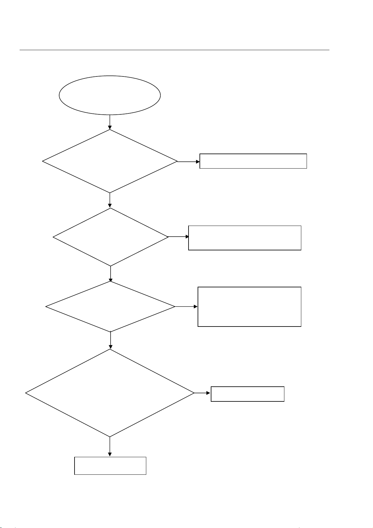
No HDMI signal output
harman/kardon
DVD 16 and 18 /230V Service Manual
Page 23 of 39
No HDMI output
Go
5-5
Trouble shooting chart
Check whether the HDMI signal
is right from the U1 pin 80, 81,
83, 84, 86, 87, 89, 90
Yes
Check whether the HDMI
signal is right from the P4
Yes
Replace P4
No
No
Check the U1 power supply
Yes
Replace the U1
Check the p4 power supply (P4 pin18
voltage is 5V)
Page 24

Exploded view for DVD16/DVD18:
harman/kardon
DVD 16 and 18 /230V Service Manual
Page 24 of 39
16
17
8-1
15
14
13
24
12
21
19
20
18
22
23
11
10
9
8
7
5
4
3
2
1
6
It is exploded view for DVD16/DVD18, pls refer to the model set for detailed information.
Assy1 includes componets:1.2.3.19.21.22
Page 25

DVD16 SERVICE PARTS
harman/kardon
DVD 16 and 18 /230V Service Manual
Page 25 of 39
Location No. TCL P/N. Description Q'ty
14 08-D03RXX-U2EX0
5 08-DVD016-FEY
11 08-DVD016-PWY
18 08-DVD016-SWY
17 08-L31808-S313D
OPU 05-000CMS-SRFS3
ASSY1 08-DV16F1-XX0B1
FLOGO 67-995950-0A0 FRONT PANEL LOGO 1
LLOGO 67-995960-0A0 LENS DVD LOGO 1
TLOGO 08-995990-XX0 TOP COVER LOGO 1
XP5 46-FH015T-05I CABLE 5PIN 150MM FH-JC20 1
XP3 46-40270C-24X FFC 180MM 24PIN 1
XP4 46-40279T-06P CABLE 6PIN UL20080#28*4 L=80MM 1
20 55-DV16D1-0HMB1 CD DOOR 1
PCORD 51-DC0150-0FAA4 POWER CORD 1
8 56-996030-0HA FOOT INDIVIDUAL (L=R) 2
10 67-VD16R1-0E0 BOTTOM PLATE 1
12 67-VD16B1-0E0B1 BACK PANEL 1
6 54-990190-000 PAD FOR TOP FOOT 2
15 67-VD16T1-0E0B1 TOP COVER 1
HDMI 46-HDI005-19G01 HDMI GILT CABLE L=0.5M 1
COAXIAL 41-UH0520-3KK1 COAXIAL CABLE L=0.52M 1
8-2
ASSY-MAIN BOARD
ASSY-FRONT CONTROL BOARD
ASSY-POWER BOARD
ASSY-SWITCH BOARD
ASSY-LOADER
OPU IM S76RFS3
ASSY-FRONT PANEL
1
1
1
1
1
1
1
SAFETY PRECAUTION
The parts identified by mark are critical for safety. Replace only with part number
specified. The mounting position of replacement is to be identical with originals.
The substitute replacement parts which do not have the same safety characteristics as specified in the
parts list may create shock, fire or other hazards.
Page 26

DVD18 SERVICE PARTS
harman/kardon
DVD 16 and 18 /230V Service Manual
Page 26 of 39
Location No. TCL P/N. Description Q'ty
14 08-D03RXX-U2EX0
5 08-DVD016-FEY
11 08-DVD016-PWY
18 08-DVD016-SWY
17 08-L31808-S313D
OPU 05-000CMS-SRFS3
ASSY1 08-DV16F1-XX0B2
FLOGO 67-995950-0A0-M FRONT PANEL LOGO 1
LLOGO 67-996040-0A0-M LENS DVD LOGO 1
TLOGO 08-995990-XX0 TOP COVER LOGO 1
XP5 46-FH015T-05I CABLE 5PIN 150MM FH-JC20 1
XP3 46-40270C-24X FFC 180MM 24PIN 1
XP4 46-40279T-06P CABLE 6PIN UL20080#28*4 L=80MM 1
20 55-DV16D1-0HMB1-M CD DOOR 1
PCORD 51-DC0150-0FAA4-M POWER CORD 1
8 56-996030-0HA-M FOOT INDIVIDUAL (L=R) 2
10 67-VD16R1-0E0-M BOTTOM PLATE 1
12 67-VD16B1-0E0B2-M BACK PANEL 1
6 54-990190-000 PAD FOR TOP FOOT 2
15 67-VD16T1-0E0B1-M TOP COVER 1
HDMI 46-HDI005-19G01 HDMI GILT CABLE L=0.5M 1
COAXIAL 41-UH0520-3KK1 COAXIAL CABLE L=0.52M 1
8-2
ASSY-MAIN BOARD
ASSY-FRONT CONTROL BOARD
ASSY-POWER BOARD
ASSY-SWITCH BOARD
ASSY-LOADER
OPU IM S76RFS3
ASSY-FRONT PANEL
1
1
1
1
1
1
1
SAFETY PRECAUTION
The parts identified by mark are critical for safety. Replace only with part number
specified. The mounting position of replacement is to be identical with originals.
The substitute replacement parts which do not have the same safety characteristics as specified in the
parts list may create shock, fire or other hazards.
Page 27

7-9
harman/kardon
DVD 16 and 18 /230V Service Manual
Page 27 of 39
Front Control Board Print-layout (Top & Bottom side):
7-9
Page 28

7-10
harman/kardon
DVD 16 and 18 /230V Service Manual
Page 28 of 39
Power Board Print-layout (Bottom side):
7-10
Switch Board Print-layout (Bottom side):
Page 29

7-11
harman/kardon
DVD 16 and 18 /230V Service Manual
Page 29 of 39
Main Board Print-layout (Top side):
7-11
Page 30

7-12
harman/kardon
DVD 16 and 18 /230V Service Manual
Page 30 of 39
Main Board Print-layout (Bottom side):
7-12
Page 31

6-1
harman/kardon
DVD 16 and 18 /230V Service Manual
Page 31 of 39
6-1
DVD16/DVD18 WIRING DIAGRAM
DVD LOADER
TDM-3+IM S76RF3
SPSP+
HOMESW
GND
SLSL+
LOADLOAD+
OUTSW
GND
INSW
1
24
1
XP5 XP4 XP3
5
1
6
24PIN*0.5
6PIN*2.0
5PIN*2.0
TER
O
DRIVER
M
1
P4
AM5888
12PIN*2.0
HDMI
SPHE8203R
XP12
CN11
COAX
16M
І㸠
FLASH
MX25L1636D
MAIN BOARD
12
1
XP1
6PIN*2.5
6
M+5V
M+5V
GND
+P12V
GND
-24V
1
XS201
6PIN*2.5
6
POWER
SUPPLY
XS601
4PIN*2.0
SW BOARD
1
4
POWER_K
GND
LEDP
LEDB
GND
M5V
IR
STB
DATA
CLK
STB_LED
12
XS301
POWER
WAKE_
SW
_K
12PIN*2.0
-24V
+12V
GND
1
VFD DISPLAY+PT6312
(VFD520)
Page 32

7-1
harman/kardon
DVD 16 and 18 /230V Service Manual
Page 32 of 39
7-1
A
Front Control Board Circuit Diagram:
+5V
R317
R317
10K
C313
C313
47pF
47pF
10K
B
R40
R40
NC/0
NC/0
1 1
2 2
REM301
REM301
GND
GND
VCC
GND
IRM_12mm
IRM_12mm
12PIN/2.0mm/120mm
12PIN/2.0mm/120mm
5
4
3
2
1
IR
XS2
XS2
12
12
11
11
10
10
9
9
8
8
7
7
6
6
5
5
4
4
3
3
2
2
1
1
IR
C312
C312
47pF
47pF
)5200$,1%2$5'
FB9 FB500/0.2AFB9 FB500/0.2A
C318
C318
C311
C311
100pF
100pF
47pF
47pF
C306
C306
0.1uF
0.1uF
C319
C319
100pF
100pF
CE301
CE301
+
+
47uF/16V
47uF/16V
C320
C320
100pF
100pF
R315 100R315 100
WAKE_SW
STB_LED
POWER_K
CLK
CS
DATA
GND
M5V
IR
-24V
+12V
GND
M5V
FB10 NCFB10 NC
A
R314 18KR314 18K
SW1
SW1
TAC020
TAC020
C314
C314
NC/47pF
NC/47pF
3DG3904M
3DG3904M
Q305
Q305
3DG3904M
3DG3904M
Q306
Q306
B
+12V
R320
R320
470
R3381KR338
1K
R3391KR339
1K
C309 0.1uFC309 0.1uF
R318 4.7KR318 4.7K
Q300
Q300
R319
R319
10K
10K
470
R321
R321
470
470
3DG3904M
3DG3904M
+12V
Q302
Q302
Q301
Q301
3DG3904M
3DG3904M
3CG3906M
3CG3906M
R316 1KR316 1K
R327 1KR327 1K
CE302
CE302
+
+
3.3uF/50V
3.3uF/50V
R341 2.2R341 2.2
R322 470R322 470
ZD303
ZD303
BZX79C6V2
BZX79C6V2
-24V
ZD301
ZD301
5.1HSC
5.1HSC
CS
CLK
DATA
+5V
CE300
CE300
47uF/16V
47uF/16V
R300 100R300 100
R301 100R301 100
R302 100R302 100
C
VFD520
33
U301
U301
34
G4
35
G3
36
G2
37
G1
38
VDD
39
LED4
40
LED3
41
LED2
42
LED1
43
GND
44
OSC
SW11SW22SW33SW44SDout5SDin6GND7SCLK8/CS9KEY110KEY2
SW1
SW2
VFD520
31
G632G5
SW3
PT6312
PT6312
-24V
26
27
23
VEE
SEG9
SEG1024SEG1125SEG12
SEG1328SEG1429SEG1530SEG16
SEG8
SEG7
SEG6/K6
SEG5/K5
SEG4/K4
SEG3/K3
SEG2/K2
SEG1/K1
VDD
KEY4
KEY3
11
R309
R309
R310
R310
10K
10K
10K
10K
VFD
VFD
AC2
32
CE303
CE303
3.3uF/50V
3.3uF/50V
R303
R303
2.2K
2.2K
C301
C301
100pF
100pF
R304
R304
2.2K
2.2K
AC1
R305
R305
2.2K
2.2K
C300
C300
100pF
100pF
C305
C305
0.1uF
0.1uF
R306
R306
51K
51K
R324 330R324 330
R325 5.6R325 5.6
+
C304
C304
0.1uF
0.1uF
C303
C303
0.1uF
0.1uF
+
C302
C302
100pF
100pF
R323
R323
10K
10K
+
+
R308
R308
D
F1F2NP3P1518P1417P1316P1215P1114P1013P912P811P710P69P58P47P36P25P14NP19NP20NP21NP221G292G283G274G265G256G247G23NP30F31F
AC2
-24V
C310
C310
+
+
0.1uF
0.1uF
22
21
20
19
18
17
16
15
14
+5V
13
12
R311
R311
2.2K
2.2K
R307
R307
10K
10K
10K
10K
C316
C316
47pF
47pF
D301
D301
FR102
FR102
AB
C317
C317
47pF
47pF
CE304
CE304
22uF/50V
22uF/50V
E
close to the XS2
M5V
4PIN/2.0mm
4PIN/2.0mm
XP1
XP1
4
4
3
3
GND
2
2
1
1
3 3
C315
C315
47pF
47pF
AMBER
BLUE
POWER_K
C308
C308
47pF
47pF
STB_LED
R41
R41
10K
10K
D2 NC/1N4148D2 NC/1N4148
R47
R47
NC/33K
NC/33K
R39 1KR39 1K
R46 NC/10KR46 NC/10K
CE6
CE6
+
+
NC/47uF/16V
NC/47uF/16V
R42 10KR42 10K
R45
R45
NC/6.8K
NC/6.8K
Q6
3CG3906MQ63CG3906M
R30
R30
4.7K
4.7K
Q8
3DG3904MQ83DG3904M
3CG3906MQ73CG3906M
R28 5.1KR28 5.1K
Q7
R29
R29
4.7K
4.7K
R31 5.1KR31 5.1K
R321KR32
1K
BLUE
AMBER
SW1 SW2 SW3
4 4
A
B
C
D
E
Page 33

7-2
harman/kardon
DVD 16 and 18 /230V Service Manual
Page 33 of 39
7-2
A
B
C
D
E
Switch Board Circuit Diagram:
1 1
SWITCH BOARD
XP1
XP1
1
1
2
2
3
3
4
2 2
4PIN/2.0mm
4PIN/2.0mm
4
C319
C319
100pF/50V/NP0
100pF/50V/NP0
D8
LED_1D8LED_1
C317
C317
100pF/50V/NP0
100pF/50V/NP0
SW301
SW301
TAC020
TAC020
C318
C318
100pF/50V/NP0
100pF/50V/NP0
3 3
4 4
A
B
C
D
E
Page 34

7-3
harman/kardon
DVD 16 and 18 /230V Service Manual
Page 34 of 39
7-3
A
B
C
D
E
Power Board Circuit Diagram:
1 1
F1
F1
T2AL/250ac
2
1
+
+
CN1
CN1
AC INPUT
AC INPUT
T2AL/250ac
2
+
+
CON1
CON1
AC INPUT
AC INPUT
1
P3P3
1
AC INPUT
1
P2P2
2 2
3 3
4
Drain
TNY176/177
TNY176/177
S5S
TR1
TR1
NTC 10&20
NTC 10&20
D1
1N4007D11N4007
RV1
RV1
10K471
10K471
1N4007D31N4007
1
2
3
NC
BP/M
U1
U1
EN/UV
S
S
8
6
7
D2
1N4007D21N4007
D3
D4
1N4007D41N4007
C5
152/1KVC5152/1KV
C9
104/50VC9104/50V
L1
680uHL1680uH
C1
C1
+
+
10uF/400V(250V/450V)
10uF/400V(250V/450V)
L6L6
R2
1/4W120KR21/4W120K
1/4W120KR31/4W120K
D8
IN4007D8IN4007
R11
R11
1/6W22
1/6W22
R13
R13
1/6W100k
1/6W100k
U2
PC123X92U2PC123X92
R3
43
C2
C2
+
+
15uF/400V(250V/450V)
15uF/400V(250V/450V)
12
TL431U3TL431
T1 EEL19T1 EEL19
5
3
2
R8
1/6W1kR81/6W1k
1
6
7
9
8
12
11
10
0.1uF/63V
0.1uF/63V
R1NUR1
NU
C11
C11
4
3
1
U3
D10 SR360/SR340D10 SR360/SR340
C14NUC14
NU
R10
R10
1/6W100
1/6W100
D5
FR102D5FR102
D7
FR102D7FR102
R9
1/6W10kR91/6W10k
+
+
C7
C7
1000uF/16V
1000uF/16V
L2
6.8uHL26.8uH
C3
C3
+
+
10uF/50V
10uF/50V
+
+
C8
C8
470uF/16V
470uF/16V
R4
1/6W10kR41/6W10k
R5
R5
1/6W12K 1%
1/6W12K 1%
R7
R7
1/6W11.3k 1%
1/6W11.3k 1%
+
C6
+
C6
47uF/25V
47uF/25V
CON2
CON2
6
-22V
5
GND
4
+12V
3
GND
2
+5V
1
+5V
6X2.5 HEADER
6X2.5 HEADER
CY1
CY1
102/400Vac
102/400Vac
* CAUTION :
THE PARTS MARKED WITH ARE IMPORTANT PARTS ON THE SAFETY.
PLEASE USE THE PARTS HAVING THE DESIGNATED PARTS NUMBER WITHOUT FAIL.
4 4
A
B
C
D
E
Page 35

7-4 7-4
harman/kardon
DVD 16 and 18 /230V Service Manual
Page 35 of 39
A
B
C
D
E
Main Board Circuit Diagram: POWER
R133 33R133 33
VCC3
TO FRONT PANEL
C126
C94
C94
100pF
100pF
R132 10RR132 10R
C91
C91
100pF
100pF
C122
C122
1uF
1uF
C123
C123
1uF
1uF
C126
0.1uF
0.1uF
GND HGNDGND RFGND
C125
C125
C124
C124
0.1uF
0.1uF
0.1uF
0.1uF
+12V
-24V
R138 1KR138 1K
C90
C90
100pF
100pF
Power Bead > 2A, RAC@100 MHz
= 70 ohm, RDC(max)= 0.4 ohm
C92
C92
100pF
100pF
C93
C93
100pF
100pF
XP12
XP12
12
11
10
9
8
7
6
5
4
3
2
1
12PIN/2mm
12PIN/2mm
TO POWER BOARD
-24V: -24V(+-10%)
+12V: +12V(+-10%)
+5V: +5V(+-2.5%)
1 1
+12V
XP1
XP1
6pin/2.5mm
6pin/2.5mm
1
2
3
4
5
6
D10
D10
27V/0.5W
27V/0.5W
R123
R123
2.2K
2.2K
GND
+12VCC
GND
0.1uF
0.1uF
C127
C127
BT3904
BT3904
Q34
Q34
11mA
Imax=1000mA
50mA
-24V
C7
0.1uFC70.1uF
L16 FB AXIALL16 FB AXIAL
VCC3
LED/PCON3
M5V
C3
0.1uFC30.1uF
R4
4.7KR44.7K
R51KR5
1K
R6 0R/NCR6 0R/NC
Q3
R8
22KR822K
8550DQ38550D
R9
10KR910K
Q2
BT3904Q2BT3904
R1 0R/NCR1 0R/NC
C1
1uFC11uF
R7
4.7KR74.7K
Q1
8550DQ18550D
R3
3.3KR33.3K
FB1 500Z 0603FB1 500Z 0603
USB_POWER 6
+12V
RFA5V
P+5V
C5
0.1uFC50.1uF
2 2
M5V
D1 RL205D1 RL205
R147
R147
1/1W
1/1W
TR_B3
TR_B33 TR_B13
REG03
3 3
REG033
Q4
Q4
2SS8550D(EBC,1.5A,1W)
2SS8550D(EBC,1.5A,1W)
R11
R11
20K/1%
20K/1%
R12
R12
12K/1%
12K/1%
GND
3.3V for 8203R and peripherals
VCC3
EC3
EC3
220uF/16V
220uF/16V
GND
C8
0.1uFC80.1uF
RF3.3V
Servo USB
L2 FBL2 FB
close to
C10
C10
EC4
EC4
0.1uF
0.1uF
100uF/16V
L7
R16 2.2R16 2.2
4.7uHL74.7uH
RFGND
VVCC3
GND
AVCC3
GND
100uF/16V
100uF/16V
100uF/16V
100uF/16V
100uF/16V
8203R
Video ADC
EC10
EC10
C18
C18
0.1uF
0.1uF
Audio
close to
C21
C21
EC12
EC12
0.1uF
0.1uF
8203R
USB_VCC
L3 FBL3 FB
EC5
EC5
100uF/16V
100uF/16V
GND
AD_VCC3
R14 10R14 10
EC11
EC11
10uF/16V
10uF/16V
GND
SPI_VCC3
L9 FB/2R2L9 FB/2R2
EC13
EC13
10uF/16V
10uF/16V
GND
SPI Flash
C9
0.1uFC90.1uF
C19
C19
0.1uF
0.1uF
C22
C22
0.1uF
0.1uF
L4 FBL4 FB
L8 FBL8 FB
DVCC3
EC6
EC6
10uF/16V
10uF/16V
GND
PLLVCC3
GND
Digital
PLL
C20
C20
0.1uF
0.1uF
0.1uF
0.1uF
TR_B1
C11
C11
REG01
REG013
R10
R10
4.7/2W
4.7/2W
Q5
Q5
2SS8550D(EBC,1.5A,1W)
2SS8550D(EBC,1.5A,1W)
2V
R133KR13
100uF/16V
100uF/16V
3K
GND
R15
R15
4.7K/1%
4.7K/1%
GND
EC8
EC8
C16
C16
0.1uF
0.1uF
VCC3
R142
R142
4.7K
4.7K
R131 0RR131 0R
M5V
IR_IN3
POWER_K3
STB_LED3
WAKE_SW3
VCC3
FB3 NCFB3 NC
VFD_DATA3
R137 1KR137 1K
VFD_STB3
VFD_CLK3
R140
R140
4.7K
4.7K
VCC3
5V for peripherals
P+5V
EC1
EC1
220uF/16V
220uF/16V
GND
0.1uFC40.1uF
M5V
R2 2.2R2 2.2
C4
L1 FBL1 FB
A+5V
RFGND
VCC5
GND
0.1uFC20.1uF
C6
0.1uFC60.1uF
C2
1.2V for core of 8203r
HAVCC
EC7
EC7
22uF/16V
22uF/16V
EC9
EC9
220uF/16V
220uF/16V
HGND
VCC1.2
GND
HDMI
C12
C12
0.1uF
0.1uF
C17
C17
0.1uF
0.1uF
0.1uF
0.1uF
C14
C14
C15
0.1uF
0.1uF
0.1uF
0.1uF
C15
C13
C13
L5 FBL5 FB
L6 FBL6 FB
EC2
EC2
100uF/16V
100uF/16V
R134 33R134 33
R135 33R135 33
R136 1KR136 1K
R139
R139
4.7K
4.7K
4 4
A
B
C
D
E
Page 36

7-5
harman/kardon
DVD 16 and 18 /230V Service Manual
Page 36 of 39
7-5
A
B
C
D
E
Main Board Circuit Diagram: SPHE8203R
PIN67---SRǃPIN68---SL
PIN70---SUBǃPIN71---C
2008.10.22
RFGND
A+5V A+5V
2627
1 1
28 25
XP3
XP3
RFGND
ELCO-CON24(Left)
ELCO-CON24(Left)
BOTTOM CONTACT
2 2
C44
C44
0.1uF
0.1uF
RFGND
M5V
FB4
FB4
FOC-
24
FOC+
23
RAD+
22
RAD-
21
C
20
D
19
LDSW
18
PUHRF
17
A
16
B
15
F
14
13
VREF1
12
11
E
10
9
CDVR#
8
DVDVR#
7
PUH_CDLD#
6
DVDMDI
5
CDMDI
4
3
PUH_DVDLD#
R149
R149
2
0/NC
0/NC
1
C133
C133
C38
C38
102
102
0.1uF
0.1uF
RFGND
RFGND
RF3.3V RF3.3V
R25
R25
EC16
EC16
5.1
5.1
47uF/16V
47uF/16V
Q6
Q6
CDLDO
2SB1132(R type)
2SB1132(R type)
PUH_CDLD
M+5V
500Z 0603
500Z 0603
C108
C108
C48
EC19
EC19
100uF/16V
100uF/16V
RFGND
0.1uF
0.1uF
C48
0.1uF
0.1uF
C36 0.1uFC36 0.1uF
C37 0.1uFC37 0.1uF
R19 0R19 0
R20 0R20 0
L10 10uHL10 10uH
L11 10uHL11 10uH
C134
C134
102
102
0.1uF
0.1uF
RFGND
C49
C49
0.1uF
0.1uF
C45
C45
A+5V
R17
R17
10K
10K
LDSW
RFGND
CDVR
DVDVR
PUH_CDLD
PUH_DVDLD
R26
R26
5.1
5.1
Q7
Q7
2SB1132(R type)
2SB1132(R type)
EC17
EC17
47uF/16V
47uF/16V
DVDLDO
PUH_DVDLD
EC15
EC15
100uF/16V
100uF/16V
RFGND
close to XP3
EC18
EC18
0.1uF
0.1uF
47uF/16V
47uF/16V
RFGND
VCC3
R27
R27
91K
91K
R28 470R28 470
C47
C47
1uF
1uF
RFGND
C39
C39
0.1uF
0.1uF
VREF1
C46
C46
VREF2VREF2DC
close to 8203R
CLKOUT
C104
C104
15pF/NC
15pF/NC
RFGND
3 3
U2
U2
1
VINFC
2
CFCerr1
3
CFCerr2
4
VINSP
5
VNFFC
6
FWD
7
REV
30
GND2
8
Vcc1
9
VOLDVOLD+10Vcc2
11
VOSP-
12
VOSP+
13
VOFC-
14
VOFC+
AM5888 BA5954
STBY
BIAS
VINTK
CTKerr1
CTKerr2
VINSL
PreGND
GND1
VCTL
VNFTK
VOSL-
VOSL+
VOTK-
VOTK+
DMEA
28
VREF2DC
27
TCO
26
TR_B3
25
24
SCO
23
22
29
21
20
19
18
17
16
15
SLED+
SLEDRADRAD+
RFGND
SP+
XOPVIP
XOPVIN
FCO
TR_B1
REG03
SPDCO
REG01
TRAY+
TRAY-
RFGND
M+5V M+5V
LOADLOAD+
R37 1R37 1
SPFOC-
FOC+
4 4
RF3.3V DVCC3
HGND
C28
C28
C109
C109
C27
C27
0.1uF
R11533R115
33
0.1uF
RFGND
X3
1 2
27MHzX327MHz
R21 4.7KR21 4.7K
C40
C40
33pF
33pF
GND
C42 1000pFC42 1000pF
C43 1000pFC43 1000pF
0.1uF
0.1uF
CLKIN
C41
C41
33pF
33pF
0.1uF
0.1uF
F
E
XOPVIP
XOPVIN
RFGND
CDMDI
DVDMDI
CDLDO
DVDLDO
RF3.3V
VREF1
RFGND
GND
PLLVCC3
CLKIN
CLKOUT
GND
USB_DM
USB_DP
USB_VCC
DVCC3
VCC1.2
GND
TCO
R23 68KR23 68K
FCO
R24 20KR24 20K
33M
VREF2
DA_TEO
DA_FEO
put these components close to 8203R
XP4XP4
6
5
4
3
2
1
XP5XP5
1
2
3
R109 1KR109 1K
4
5
SLED+
SLED-
HOME
SP+
SP-
LOADLOAD+
TRAYOUT
TRAYIN
RFGND
RFGND
RFGND
RF3.3V
RFGND
PUHRF
0.1uFC25 0.1uFC25
1uFC24 1uFC24
LDSW
C
HOMELED/PCON
96
100
99
94
98
93
97
95
RFIS
DVDD
DVDC
LDSW
AGCCAP
AD_AVSS
AD_AVDD
HOME/GPIO
CDVR/GPIO/SC1_OUT
TRAYOUT/GPIO/DFCT
TRAYIN/GPIO/FGIN
TRAY+/GPIO/TRAY_OUT
Home/GPIO11
GPIO1210GPIO1311SPI_CE12SPI_D013SPI_CLK14SPI_D115VDD_3321RESET_B22VSS
4
5
6
7
8
9
TRAYIN
CDVR
TRAY+
TRAYOUT
DVDVR
200K max
Added the reference point
DVCC3
EC20
EC20
10uF/16V
10uF/16V
R39
R39
10K
10K
GND
HOME
TRAYOUT
TRAYIN
U1
U1
103
CDF
104
CDE
105
OPVIP
106
OPVIN
107
RF_APC_AVSS
108
CDMDI
109
DVDMDI
110
CDLDO
111
DVDLDO
112
SRV_AVDD
113
V21
114
DA_AVSS
115
PLL_VSS
116
PLL_VDD
117
CLKIN
118
CLKOUT
119
USB_AVSS
120
USB_DM
121
USB_DP
122
USB_AVDD
123
VDD_33
124
VDD_12
125
GND
126
V165
127
DA_TEO
128
DA_FEO
TRAY- LDSW
RF3.3V
LOAD+
LOAD-
D
A
B
102
101
DVDB
DVDA
SC_OUT2DMEA3DVDVR/GPIO/STEP_OUT
SPDC_OUT
1
SPDC_OUT
DMEA
SC_OUT
R292.2K R292.2K
R302.2K R302.2K
SPDCO
SCO
0.1uF C500.1uF C50
0.1uF C510.1uF C51
RFGND
R35 0R35 0
R32 4.7KR32 4.7K
R33 4.7KR33 4.7K
R34 4.7KR34 4.7K
C55 0.1uFC55 0.1uF
C56 0.1uFC56 0.1uF
for EMI
Pickup head parameter
C43
1000P
1000P
1000P
1000P
R23
91K
91K
R24
Sony 313
20K
20K
Samsung 68K
Mitsumi 91K 680P
20K
20K
HGND
HAVCC
RF3.3V
TX1-
TX2-
TX2+
TX1+
92
88
90
87
91
85
89
86
TX2-
TX1-
TX2+
TX1+
HAVCC
HPGND
AD_AVDD
SPHE8203R-128
SPHE8203R-128
IR/GPIO16VFD_CLK/GPIO
17
18
SPI_CE
VFD_CLK
SPI_D0
SPI_CLKIN
VFD_STB
IR_IN
SPI_D1
R310R31
0
SPI_CLK
Place near 8203R
R38 100R38 100
D4
1N4148D41N4148
C52
C52
0.1uF
0.1uF
RFGND
RFGND
R19
C42
680P
1000100
680PSanyo HD65
1000P
0
00
HGND
HAVCC
TX0+
TXC+
TX0-
TXC-
82
84
80
79
83
81
TX0-
TXC-
TX0+
TXC+
HAVCC
HAGND
VFD_STB/GPIO
VFD_DAT/GPIO
VDD_12
24
23
19
20
RX2
VFD_DATA
RESET_B
GND
DVCC3
VCC1.2
R102
R102
R36
R36
NC/22
NC/22
10K/47
10K/47
Q8
2N3904Q82N3904
C53
C53
0.1uF
0.1uF
Place near XP5
R20
0
0
HGND
GND
AOUT_FR
AOUT_FL
R18 5.1KR18 5.1K
75
77
78
76
HAGND
AOUT_L
AOUT_R
EXT_SWING
ADAC_AVSS
VSYNC(1)/TX(1)/GPIO
HSYNC(1)/RX(1)/GPIO
SD_D0/GPIO28SD_D3/GPIO
SD_CLK/GPIO
SD_CMD/GPIO27CARD_SENSE/GPIO
25
26
TX2
WAKE_SW
R118
R118
NC/2.2
NC/2.2
R117
R117
0/2.2K
0/2.2K
AVCC3
AOUT_C
DAC_VREF
73
74
71
72
VREF
ADAC_AVDD
ADAC_AVDD
SD_D1/GPIO
SD_D2/GPIO
29
31
30
32
STB_LED
POWER_K
ǃ
DŽ
GND
GND
AOUT_SUB
AOUT_SL
AOUT_SR
70
69
67
68
AOUT_LS
AOUT_RS
AOUT_SUB
ADAC_AVSS
AOUT_CENTER
HDMI_CEC/GPIO
HDMI_HPD/GPIO
CARD_RST/GPIO
GAME_D1/I2S_D2
GAME_D0/I2S_D1
GAME_LATCH/I2S_D0
33
34
35
36
C99
C99
C57
C57
NC/1uF
NC/1uF
0.1uF
0.1uF
place components near to 8203R
EC14
EC14
10uF/16V
10uF/16V
65
66
AIN_R
AD_AVSS
A_MUTE/GPIO
GAME_CLK/RX2
37
AD_AVDD
TV_AVSS
TV_DAC3
TV_DAC2
TV_DAC1
TV_AVDD
TV_AVSS
TV_AVDD
TV_DAC0
V_FSADJ
V_COMP
VDD_33
VDD_12
SPDIF_OUT
SPDIF_IN
DDC_SCL
DDC_SDA
I2S_XCLK
I2S_BCLK
I2S_LRCLK
I2S_DATA_IN
GPIO/TX2
VDD_33
38
DVCC3
SPI_VCC3
RESET_B
GND
64
63
62
61
60
59
58
57
56
55
54
53
52
51
50
49
48
47
46
45
44
43
42
41
40
39
VSS
TX2
RX2
C115
C115
100pF
100pF
GND
DAC_VREF
C23
C23
0.1uF
0.1uF
GND
TV_DAC3
TV_DAC2
TV_DAC1
TV_DAC0
V_FSADJ
V_COMP
SPDIF_OUT
AUDIO_MUTE
DDC_SCL
DDC_SDA
HDMI_CEC
HDMI_HPD
SCART_SIG
SCART_DIS
SCART_REL
RGB/YUV_SW
M5V
C116
C116
100pF
100pF
4pin/2.0mm
4pin/2.0mm
AD_VCC3
GND
GND
10uF/16V
10uF/16V
DVCC3
VCC1.2
GND
XP2
XP2
1
2
3
4
EC21
EC21
DVCC3
C30
C30
C29
C29
C31
C31
0.1uF
0.1uF
0.1uF
0.1uF
0.1uF
0.1uF
GND GND
VVCC3
C26
C26
0.01uF
0.01uF
GND
R22
R22
27K
27K
D5
1N4148D51N4148
SPI_CE
DQ0
SPI_WP
GND
SPI_VCC3
C32
C32
0.1uF
0.1uF
U3
U3
1
CE_B
2
DQ0
3
WP#
GND4DQ1
SPI FLASH-DIP8
SPI FLASH-DIP8
R40 0R40 0
R41 0R41 0
R42 10KR42 10K
R43 10KR43 10K
R67 10KR67 10K
R101 NC/10KR101 NC/10K
GND
HOLD#
VDD
SCK
VCC1.2
C33
C33
0.1uF
0.1uF
8
7
6
5
DQ0SPI_D0
DQ1SPI_D1
SPI_WP
SPI_HOLD
SPI_CE
C34
C34
0.1uF
0.1uF
SPI_HOLD
SPI_CLK
DQ1
POWER_K
STB_LED
WAKE_SW
TV_DAC3
TV_DAC2
TV_DAC1
TV_DAC0
V_FSADJ
IR_IN
VFD_CLK
VFD_STB
VFD_DATA
AOUT_FR
AOUT_FL
AOUT_SR
AOUT_SL
AOUT_SUB
AOUT_C
SCART_SIG
SCART_DIS
SCART_REL
RGB/YUV_SW
SPDIF_OUT
AUDIO_MUTE
USB_DM
USB_DP
TR_B1
TR_B3
REG01
REG03
DDC_SCL
DDC_SDA
TXC+
TXCTX0+
TX0TX1+
TX1TX2+
TX2HDMI_HPD
HDMI_CEC
LED/PCON
0.1uF
0.1uF
C35
C35
SPI_VCC3
GND
C54
C54
0.1uF
0.1uF
POWER_K 2
STB_LED 2
WAKE_SW 2
TV_DAC3 4
TV_DAC2 4
TV_DAC1 4
TV_DAC0 4
V_FSADJ 4
IR_IN 2
VFD_CLK 2
VFD_STB 2
VFD_DATA 2
AOUT_FR 5
AOUT_FL 5
AOUT_SR 5
AOUT_SL 5
AOUT_SUB 5
AOUT_C 5
SCART_SIG 4
SCART_DIS 4
SCART_REL 4
RGB/YUV_SW 4
SPDIF_OUT 5
AUDIO_MUTE 5
USB_DM 6
USB_DP 6
TR_B1 2
TR_B3 2
REG01 2
REG03 2
DDC_SCL 6
DDC_SDA 6
TXC+ 6
TXC- 6
TX0+ 6
TX0- 6
TX1+ 6
TX1- 6
TX2+ 6
TX2- 6
HDMI_HPD 6
HDMI_CEC 6
LED/PCON 2
A
B
C
D
E
Page 37

7-6
harman/kardon
DVD 16 and 18 /230V Service Manual
Page 37 of 39
7-6
A
B
C
D
E
Main Board Circuit Diagram: VIDEO
P+5V
R11233R112
33
R111
R111
2.4K
1 1
2 2
3 3
P1
P1
SCART/AV OUT
SCART/AV OUT
1
2
3
4
5
6
47-SCA008-XX0
47-SCA008-XX0
7
8
SCART
SCART
9
10
11
12
13
14
15
16
17
18
19
20
21
GND
GND
GND
GND
GND
GND
GND
GND
SCART_DIS
SCART_REL
P+5V
SCART_SIG
R124
R124
470
470
+12V
GND
AUDIO/TV/16:9
SCART_SWITCH
SCART_CVBS_OUT
C66
C66
100pF
100pF
3
D6
BAT54SD6BAT54S
1
2
P+5VGND P+5VGND P+5VGND
R119
R119
470
470
R59 1.5KR59 1.5K
R62 1.5KR62 1.5K
D12
D12
12V/0.5W
12V/0.5W
R651KR65
1K
R66
R66
100K
100K
BT3904
R61 75RR61 75R
R60 4.7KR60 4.7K
BT3904
B_OUT
G_OUT
R_OUT
C67
C67
C68
C68
100pF
100pF
100pF
100pF
3
D7
BAT54SD7BAT54S
1
2
Close to P1
R631KR63
1K
Q17
Q17
BT3904
BT3904
GND
Q19
Q19
GND
SCART_SWITCH
R641KR64
1K
C69
C69
100pF
100pF
GND
SCART_R
SCART_L
C70
C70
C71
C71
100pF
100pF
100pF
100pF
3
1
AUDIO/TV/16:9
Q18
Q18
BT3904
BT3904
2
D8
BAT54SD8BAT54S
G_OUT
B_OUT
R_OUT
CVB1 CVBS_BU
L12 1uH/0RL12 1uH/0R
C62
C62
100pF
100pF
GND
RGB/YUV_SW OUT
1 R,G,B
0 Y,U,V
Q9 MMBT3904Q9 MMBT3904
R51
R51
4.7K
4.7K
Q11 MMBT3904Q11 MMBT3904
R53 4.7KR53 4.7K
MMBT3904
MMBT3904
Q15 MMBT3904Q15 MMBT3904
R57 4.7KR57 4.7K
EC29 220uF/16v
EC29 220uF/16v
R11091R110
C100
C100
91
100pF/NC
100pF/NC
R501KR50
1K
10
GND
R54 4.7KR54 4.7K
R561KR56
Y-R-V_OUT G-Y_OUTC-B-U_OUT
RGB/YUV_SW
Q13
Q13
2.4K
CVBS_IND CVBS_OUT
Q28
R113
R113
1.2K
1.2K
R491KR49
1K
MMBT3904
MMBT3904
Q28
BT3904
BT3904
R116
R116
100 1%
100 1%
GND
R52
R52
R55
R55
R58
R58
+
+
P+5V
Q14
Q14
1K
GND
SCART_CVBS_OUT
Q10 MMBT3904Q10 MMBT3904
4.7K
4.7K
MMBT3904
MMBT3904
Q12
Q12
4.7K
4.7K
MMBT3904
MMBT3904
Q16
Q16
4.7K
4.7K
Y_OUT
U_OUT
V_OUT
C63
C63
100pF
100pF
NCC59 NCC59
0.22uH/0R
0.22uH/0R
L13
L13
C101
C101
100pF/NC
100pF/NC
CVBS_IND
CVBS_BU
G-Y_OUT
C-B-U_OUT
Y-R-V_OUT
C64
C64
100pF
100pF
GNDGND
R44 75/1%R44 75/1%
GND
R45 82/1%R45 82/1%
R46 82/1%R46 82/1%
R47 82/1%R47 82/1%
R48 1kR48 1k
Close to 8203R
R161 0/NCR161 0/NC
R153 0/NCR153 0/NC
R154 0/NCR154 0/NC
R155 0/NCR155 0/NC
R156 0/NCR156 0/NC
NCC60 NCC6010pF/NCC58 10pF/NCC58
0.22uH/0R
0.22uH/0R
L14
L14
CVBS_OUT
C72
C72
100pF
100pF
U_OUT
V_OUT
C102
C102
100pF/NC
100pF/NC
CVB1
G/Y
B/U
R/V
V_FSADJ
Y_OUT
C73
C73
100pF
100pF
R/V Y-R-V_OUTB/U C-B-U_OUTG/Y G-Y_OUT
GND
RCA/VIDEO OUT
RCA/VIDEO OUT
GND
GND
U_OUT
V_OUT
C75
C75
C74
C74
100pF
100pF
100pF
100pF
Vidoe out
U6
U6
1
2
3 4
PESD3V3L5UY
PESD3V3L5UY
ESD Protection
C65
C65
100pF
100pF
6
5
0.22uH/0R
0.22uH/0R
L15
L15
1
2
3
4
5
6
NCC61 NCC61
C103
C103
100pF/NC
100pF/NC
CVB1
G/Y
B/U
R/V
V_FSADJ
SCART_SIG
SCART_DIS
SCART_REL
RGB/YUV_SW
SCART_R
SCART_L
P2
P2
47-RCA150-XX1
47-RCA150-XX1
RCA
RCA
Close to P2
CVBS_OUT
Y_OUT
TV_DAC0 3
TV_DAC1 3
TV_DAC2 3
TV_DAC3 3
V_FSADJ 3
SCART_SIG 3
SCART_DIS 3
SCART_REL 3
RGB/YUV_SW 3
RCH 5
LCH 5
4 4
RELEASE_SCART
DISPLAY_MODE
Not RELEASE0
1
RELEASE
SCART_DISPLAY1DISPLAY_MODE
12V(9.5V--12V 4:3)0
6V(5V--8V 16:9)
SCART_SIG
A
0
1
SIGNAL_MODE
0V(CVBS)
3V(RGB)
B
C
D
E
Page 38

7-7
harman/kardon
DVD 16 and 18 /230V Service Manual
Page 38 of 39
7-7
A
B
C
D
E
Main Board Circuit Diagram: AUDIO
1 1
M5V
Q20
Q20
()
C86
C86
1000pF
1000pF
R77
R77
3.3K
3.3K
R162 22R162 22
R163 33R163 33
Power on mute
R76
R76
10K
10K
Power off mute
Added the COAX ports
EC30
EC30
47uF/16V
47uF/16V
R68 27KR68 27K
C76 82pFC76 82pF
V_REF
-
-
2
+
+
3
8 4
AVCC12
C79 82pFC79 82pF
-
-
6
+
+
5
8 4
C84
C84
0.1uF
0.1uF
GND
EC23 10uF/16VEC23 10uF/16V
1
U4A
U4A
NJM4558
NJM4558
GND
EC26 10uF/16VEC26 10uF/16V
7
U4B
U4B
NJM4558
NJM4558
R88 36KR88 36K
R73 470R73 470
R75 470R75 470
R74
R74
10K
10K
GND
MUTE
R83 470R83 470
R86 470R86 470
R85
R85
10K
10K
GND GND
V_REF
EC27
EC27
R90
R90
10k
10k
100uF/16V
100uF/16V
C83
C83
0.1uF
0.1uF
C82
C82
0.1uF
0.1uF
GND
Q21
Q21
3904
3904
Q24
Q24
3904
3904
RCH
LCH
SPDIF_OUT
AUDIO_MUTE3
R91 200R91 200
R71
VCC12V
C150
C150
0.1uF
0.1uF
R71
7.5K
7.5K
R81
R81
7.5K
7.5K
R72 1.2KR72 1.2K
C78
C78
1500pF
1500pF
GND
R82 1.2KR82 1.2K
C81
C81
1500pF
1500pF
R89 100R89 100
R78 27KR78 27K
V_REF
AVCC12
EC28
EC28
100uF/25V
100uF/25V
AOUT_FR
R70 3kR70 3k R84
C77
C77
220pF
220pF
GND
2 2
AOUT_FL
R80 3kR80 3k
C80
C80
220pF
220pF
GND GND AVCC12
+12V
R130 33R130 33
GND
VCC3
R164
R164
4.7K/NC
4.7K/NC
R84
4.7K
4.7K
COAXIAL
0.1uFC87 0.1uFC87
LCH
C88
C88
R92
R92
100
100
10pF
10pF
RCH
P+5V
R79
R79
4.7K
4.7K
Q23
Q23
BT3904
BT3904
R87
R87
22K
22K
GND
C85
C85
1000pF
1000pF
GND
mute circuit
EC24
EC24
220uF/16V
220uF/16V
OPTICALSPDIF_OUT
GND
C120
C120
0.1uF
0.1uF
GND
3906
3906
R69
R69
22k
22k
CN11
CN11
1
2
3
COAX OUT
COAX OUT
1
2
3
4
5
6
7
8
9
P3
P3
RCA+OPTICAL
RCA+OPTICAL
MUTE
AOUT_FR
AOUT_FL
SPDIF_OUT
SCART_R
SCART_L
AOUT_FR 3
AOUT_FL 3
SPDIF_OUT 3
RCH 4
LCH 4
Q22
Q22
3906
3906
+
+
C113
C113
10pF
10pF
GND
RCA/AUDIO OUT
RCA/AUDIO OUT
C121NCC121
NC
3 3
AOUT_SL3
AOUT_SR3
AOUT_C3
AOUT_SUB3
GND
VCC12V
R157 3kR157 3k
R158 3kR158 3k
R159 3kR159 3k
R160 3kR160 3k
C112
C112
100pF/NC
100pF/NC
GND
GND
C105
C105
220pF
220pF
C106
C106
220pF
220pF
C107
C107
220pF
220pF
MUTE
C110
C110
220pF
220pF
C111
C111
0.1uF
0.1uF
GND
GND
XP9XP9
8PIN/2.0mm*8
1
2
TO AV BORAD
3
4
5
6
7
8
AUDIO OUT
4 4
A
B
C
D
E
Page 39
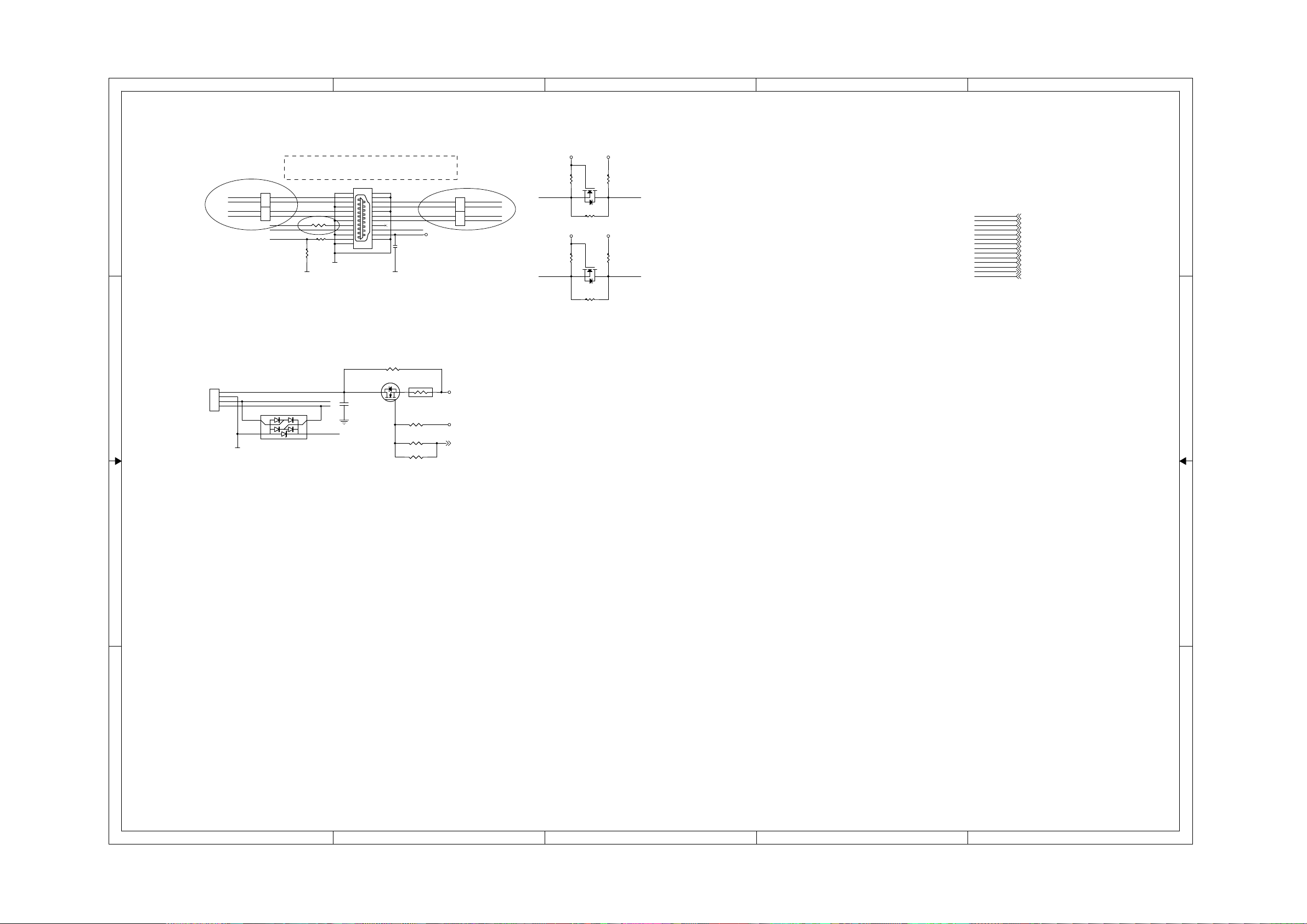
7-8
harman/kardon
DVD 16 and 18 /230V Service Manual
Page 39 of 39
7-8
A
B
C
D
E
Main Board Circuit Diagram: HDMI&USB
VCC3
Differential signals (TXC+/-, TX1+/-, TX2+/- and TX3+/-):
50ohm single_ended, and 100ohm differential
HGND
P4
21
1 2
3 4
5 6
7 8
9 10
11 12
13 14
15 16
17 18
19
20
HDMIP4HDMI
VCC_USB
C96
C96
0.1uF
0.1uF
23
DSDADSCL
22
C89
C89
0.1uF
0.1uF
R174 0/0805/NCR174 0/0805/NC
Q33
Q33
AO3402
AO3402
F1
23
800mAF1800mA
1
R120 4.7KR120 4.7K
R108 NC/(180)R108 NC/(180)
R150 NC/(180)R150 NC/(180)
ACM2012
ACM2012
VCC5
FL3
FL3
123
4
123
FL4ACM2012 FL4ACM2012
4
M5V
+12V
USB_POWER 2
TX1+
TX1-
TXC+
TXC-
VCC3
DDC_SDA DSDA
1 1
2 2
XP7XP7
4PIN/2.0mm
1
2
3
4
USB OUT
TX2+
TX2-
TX0+
TX0-
GND
123
FL1 ACM2012FL1 ACM2012
4
123
FL2 ACM2012FL2 ACM2012
4
HDMI_CEC
HDMI_HPD
USB_DM
USB_DP
U5
U5
2
1
PRTR5V0U2X
PRTR5V0U2X
R96 0R/NCR96 0R/NC
R95 20KR95 20K
R99
R99
51K
51K
HGND HGND
3
VCC_USB
4
R104
R104
2
4.7K
4.7K
1
Q25 2SK3018
R152 0/NCR152 0/NC
R106
R106
2
4.7K
4.7K
1
Q26 2SK3018
R151 0/NCR151 0/NC
3
3
VCC5
VCC5
R105
R105
1.8K
1.8K
R107
R107
1.8K
1.8K
DSCLDDC_SCL
USB_DM
USB_DP
TXC+
TXCTX0+
TX0TX1+
TX1TX2+
TX2DDC_SCL
DDC_SDA
HDMI_HPD
HDMI_CEC
USB_DM 3
USB_DP 3
TXC+ 3
TXC- 3
TX0+ 3
TX0- 3
TX1+ 3
TX1- 3
TX2+ 3
TX2- 3
DDC_SCL 3
DDC_SDA 3
HDMI_HPD 3
HDMI_CEC 3
3 3
4 4
A
B
C
D
E
 Loading...