

Page 1
harman consumer group
SERVICE CENTER TRAINING GUIDE
Servicing
DSP
By Andy Andersen
Page 2

Harman Consumer Group 250 Crossways Park Dr. Woodbury New York 11797
Email techsupport@harman.com Web www.harmanservice.com
DSP technology is a very broad term covering many
different functions and purposes in the world of
electronics. The basic function of DSP is to take
some form of digital data and make sense out of it
for our hardware. It sounds fairly simple but it’s a
complex and growing portion of today’s advanced
audio equipment. The possibilities, features, and
enhancements capable with DSP may be enough to
discourage anyone but the architect from
understanding it.
Luckily, there are enough consistencies in the DSP
section of today’s home audio video receivers so that
we don’t have to specialize in designing them in
order to repair them. Our mission today is to
provide the fundamentals for approaching a DSP
related problem using standard troubleshooting
techniques.
Page 3

Page 3
DSP Service
Know what works!!!!
Tame the beast.
If the unit under test turns on and stays on;
Do the 6/8 channel analog test 1
Using the 6/8 input will quickly isolate audio problems in an AVR
receiver. Most audi
o problems are not DSP related but are common
Analog and power supply problems. Please review Tech Tip
TIP#HKTT2004-03 Isolating audio problems in an AVR receiver
Using 6/8 Direct In.
Use the following procedures to help find what is working, then
to locate the problem area.
Equipment needed:
; 1 set of (RCA) Y adaptors.
; Function/signal generator.
; Oscilloscope.
Procedure:
1) Do a factory reset of the receiver. (This may eliminate common micro
processor problems.)
2) Print the block diagram from the service manual.
3) With no inputs or speakers attached to the AVR turn on the receiver and
turn the volume all the way down.
Turn unit off.
4)
5) Hook up an oscillator to the 6/8 Direct in jacks using the Y adaptors. Adjust
the oscillator to about 0db (.775Volts RMS).
6) Hook up an oscillosc
out (preamp out) jacks monitor the input to the power amps or the speaker
outs. (AVR125, 225, 130 do not have preamp out jacks)
7) Turn the AVR on. Select 6 or 8 direct in, depending on the receiver.
Slowly turn the volume control up until you can easily measure the voltage
8)
at the line out jacks. ( -40 to -25db )
9) At this point you will be able to check and assure all output levels are the
same.
IF THE OUTPUT LEVELS ARE NOT THE SAME STOP! Go no further. At
10)
this point you will need to use the charts to see where you are losing your
signal. The chart shows the analog signal flow from the input jacks to the
output jacks.
11) If the output levels are the same check the power out stage at the speaker
out jacks.
12) If you find the levels at the speaker out jacks are OK, your problem will be in
the DSP part of the receiver.
Congratulations! You have now eliminated 90% of the electronics in the AVR and
confirmed that the problem
ope to monitor the line out jacks. Or, if there are no line
st
!!
is in the DSP section.
Harman Consumer Group 250 Crossways Park Dr. Woodbury New York 11797
Email techsupport@harman.com Web www.harmanservice.com
Page 4
Page 4
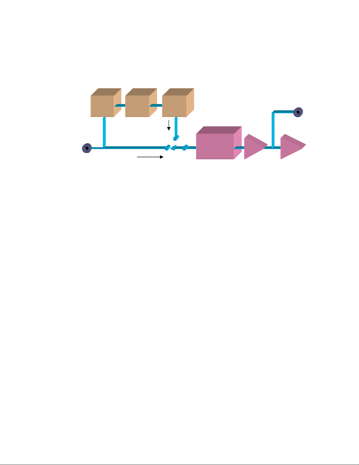
If it fails, repair the analog portion of the AVR first
before proceeding with the DSP check.
ADC
DSP
DAC
8/6 Ch.
Analog
Input
DSP
Analog
Analog flow chart
Master
Volume
Control
Power Amps
Figure 1.
What does work!
If the Analog passes through this is what we know.
1. The Analog path is OK from the input 6/8 channel direct jacks
to the preamp out or the power amps.
2. Input selector switch is OK along with the +/- 15 volt power
supply and the digital control of the device.
3. DSP, analog, 6/8 selector switch is OK.
4. Master Volume control is OK.
5. Power amps, and Op Amps are OK.
6. The main micro and sub micros along with the front panel
display.
7. Clock, Data, CE lines to all controlled devices in the analog
path are OK
8. Main Power supply voltages including the 5 volt, +/- 15 volt and
some times a 3.3/2.5 volts for the DSP and micro.
Preamp
Out
Harman Consumer Group 250 Crossways Park Dr. Woodbury New York 11797
Email techsupport@harman.com Web www.harmanservice.com
Page 5
Moving on to DSP check.
Page 5
Setup your bench for ease of service.
Equipment needed:
Dvd with Coaxial and TOSLINK (optical) S/P DIF out
Dolby Digital test disk (must include a 400Hz -20 dbfs sine wave Dolby Prologic
signal, and a 30Hz -3 dbfs sine wave Dolby signal)
1 set of (RCA) Y adaptors to check analog path.
1 Toslink cable (optical)
1 Coaxial cable (or a good quality audio cable)
Function/signal generator for analog path.
Oscilloscope.
TIP:
Try not to use the speakers for DSP service. Too many wires can
lead to confusion, and mistakes can easily be made. If the amp has
preamp out jacks, use them! If you are still in the preliminary test
setup continue to use speakers until all of the failures can be
identified. Once the cover has been removed for servicing, there is no
further need to use the speaker out jacks to service the DSP board.
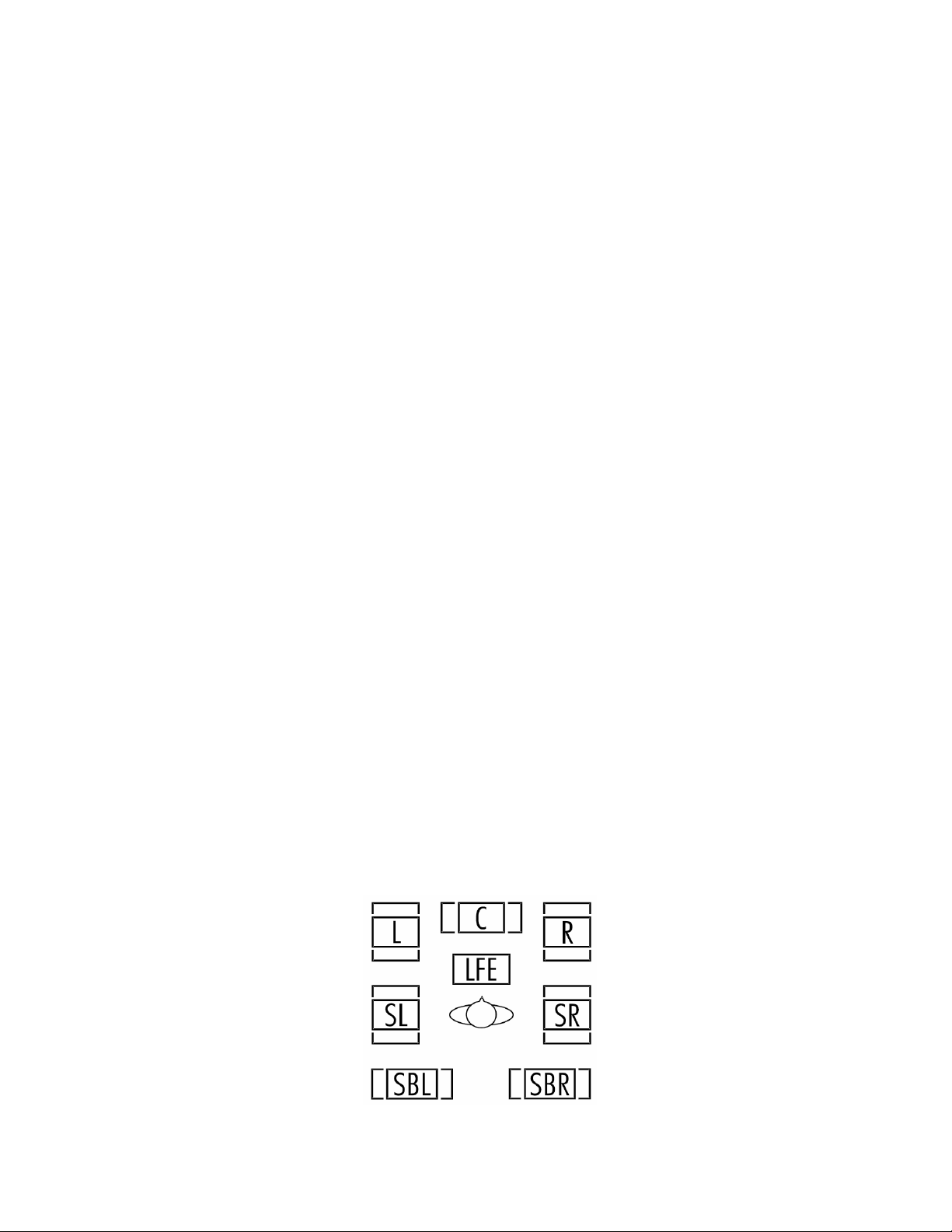
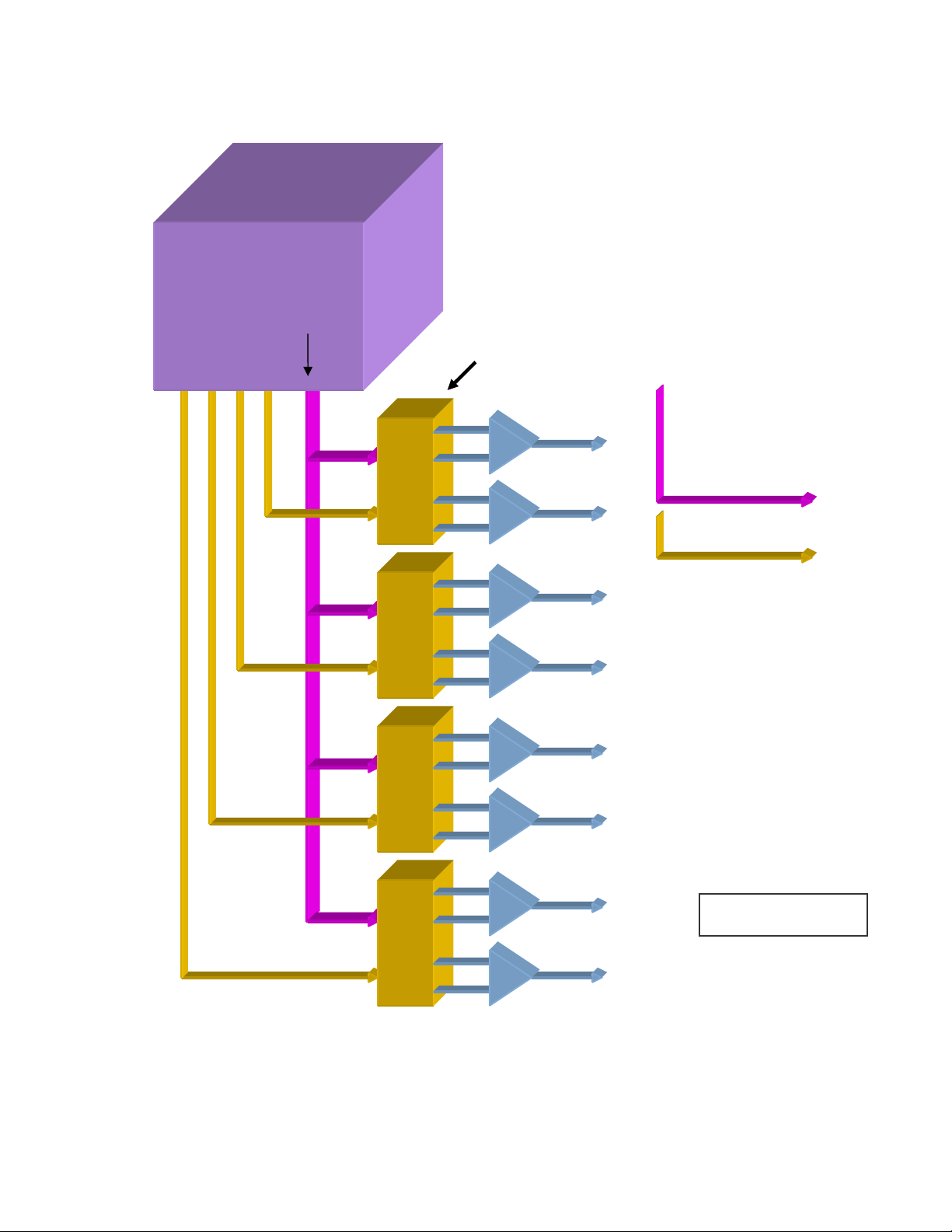
Step 1:
Do an AVR speaker test. You will need a remote control to perform
this test on most AVRs.
This will test ½ of the DSP board. The speaker test tones are
generated from inside the DSP chip. The first thing that will happen is
the microprocessor has to communicate with the DSP chip. If the
DSP successfully receives the signal the DSP will return a signal to
let the micro know what speaker is being tested. You will see what
speaker is passing the test tone by seeing that speaker flash. If the
DSP and the DACs are working, the amplitude will be the same for all
channels including the subwoofer.
Figure 2.
Harman Consumer Group 250 Crossways Park Dr. Woodbury New York 11797
Email techsupport@harman.com Web www.harmanservice.com
Page 6
Whew!!
Page 6
That is a lot of information so far, but if successful we now know
a few things:
1. The DSP chip can communicate to the micro.
2. The voltages to the dsp are probably ok.
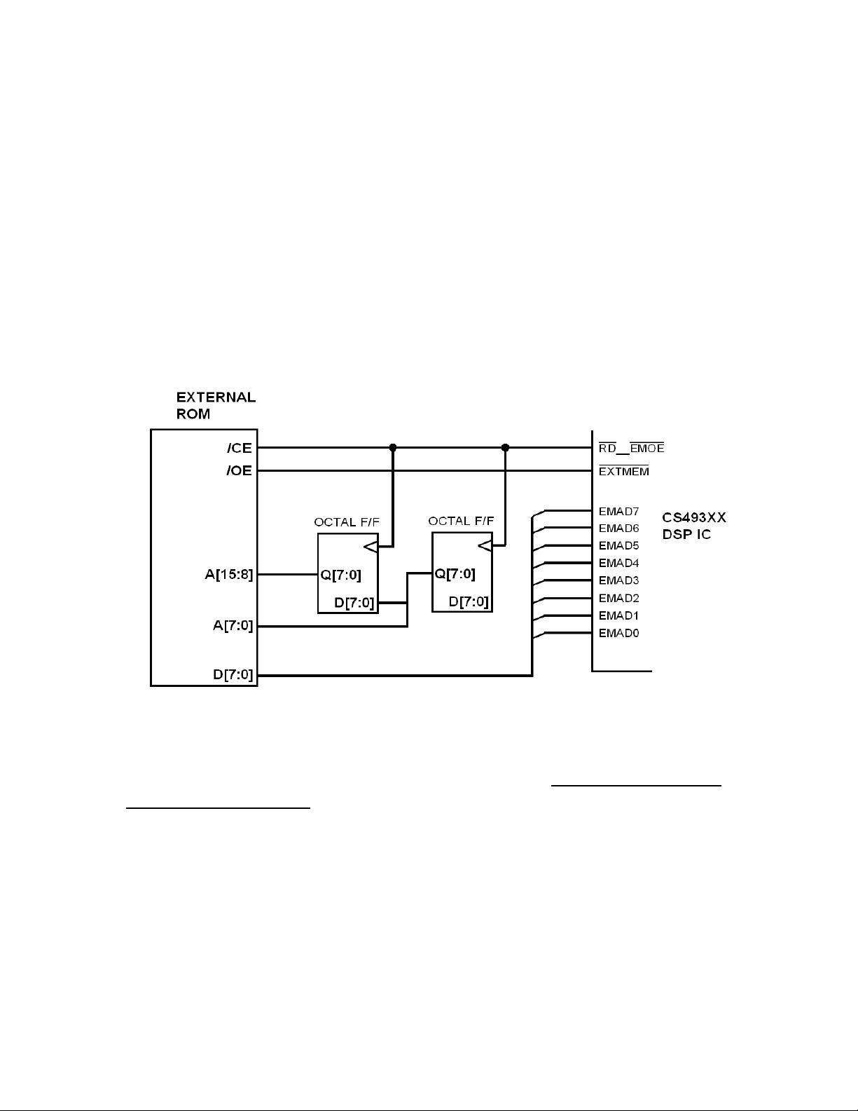
3. If the DSP IC has an Eprom, the Eprom was successful in booting
the DSP chip. (this does not mean the Eprom is ok but that it is not
dead)
4. The DACs are communicating with the DSP
5. There is analog audio from the DACs through the op-amps.
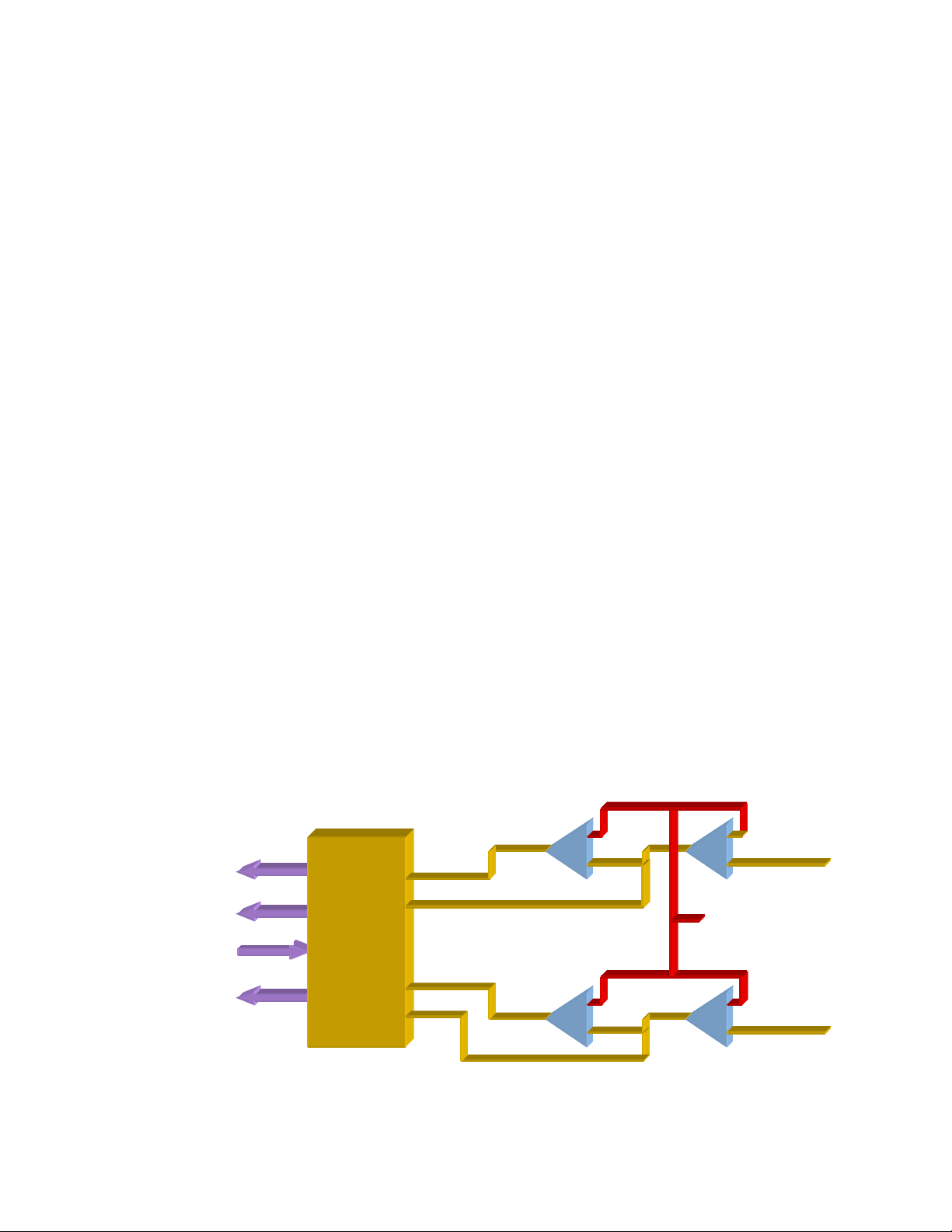
DSP Eprom data flow
Figure 3.
Now we are looking to see audio at the preamp out jacks. This is just
a go/no-go check to see if we see the signal and the amplitude is the
same on all channels.
TIP:
Make a checklist that you can use to check all modes.
If the speaker test checks out OK, we now know some more of
the receiver that works.
1. The Data lines from the DSP to the DAC works.
2. The DACs work.
3. The Op Amps work.
Harman Consumer Group 250 Crossways Park Dr. Woodbury New York 11797
Email techsupport@harman.com Web www.harmanservice.com
Page 7
k
Page 7
4 Lines
of Data
DSP IC
L/R Cloc
Slave Clock
Master Clock
DSP IC
Chip Enable
4 Lines of
DATA Out
DAC
+
-
+
-
+
-
+
-
+
-
+
-
SL
L/R Clock
Slave Clock
Master Clock
Chip Enable
Data Lines
+
-
+
-
SR
+
-
+
-
CNT
+
-
+
-
+
-
+
-
+
-
+
-
SW
SBL
AVR 520
SBR
Figure 4.
Block of what is happening from the DSP to the audio out.
Harman Consumer Group 250 Crossways Park Dr. Woodbury New York 11797
Email techsupport@harman.com Web www.harmanservice.com
Page 8

Page 8
Review:
What we know works:
CPU data to and from the DSP is OK
½ of the DSP is OK
Your voltages to the DACs are OK
+/- 15 volt line to the Op Amps are OK
Most of the DSP IC voltages are OK
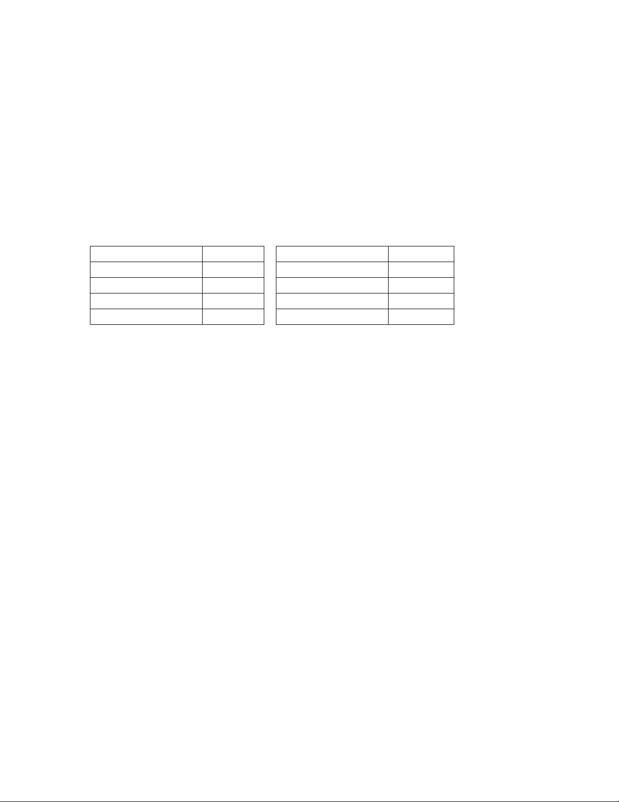
AVR 525
CS4382
+5VD +V Digital Side +5VA +V Analog side
+5VA +V Analog Side +3.3VL +V Logic/Dig side
+3.3V +V Logic
AVR 520
CS4391
AVR 635
CS42518CQ
+5VA +V Digital Side +/- 15 volts 5V
+5VD +V Analog Side 3.3V
+3.3 VLB +V Logic 2.5V
1.24V
Voltages of common DACs, DSP, and Op Amps
What have we not checked so far?
1. Any input to the DSP.
2. The DSP clock frequency.
3. PCM or any compressed decoding ( Dolby Digital, MPEG)
4. PCM matrix coding (Harman’s Logic 7 )
5. Analog to digital conversion
6. Coax in
7. Toslink in (optical)
OP-AMPS DSP ICs
Figure 5.
Harman Consumer Group 250 Crossways Park Dr. Woodbury New York 11797
Email techsupport@harman.com Web www.harmanservice.com
Page 9

Page 9
Next we need to check the input to the DSP.
We have 3 types of signals to check.
1. Analog (converted to serial data)
2. PCM (44.1khz CD)
3. Compressed digital (96khz Dolby digital, Mpeg, 44.1khz
Mp3)
Let’s start with the digital input.
Set up the bench using a DVD player for a source and
test cd or cds.
NOTE on Test Disk:
Must have a
Mono 400hz at –20db 44.1khz
Mono 30hz at –3db 44.1khz
Stereo music track 44.1khz
Mono 5 tracks 400hz at –20db Dolby digital
1 track 30hz at –3db Dolby Digital 96khz
1 Track f
Start with the CD using 400hz and 30hz Mono CD audio (PCM
44.1khz)
ull audio all channels.
96khz
If you get audio next check the stereo music track. If OK
Now check using Dolby Digital. First check using the tones, then the
music track.
If all of this passes….
Then there is nothi
… Just kidding!!!
This procedure should be the final check before service and done
after the unit is serviced.
A reminder:
This is done with the cover on, and does not need to be done by
the tech that is d
important, and if done correctly it will reduce time spent, while
improving the overall quality of service.
ng wrong with this unit.
oing the service. This procedure is a very
Harman Consumer Group 250 Crossways Park Dr. Woodbury New York 11797
Email techsupport@harman.com Web www.harmanservice.com
Page 10

Page 10
IF DONE CORECTLY, SERVICE TIME WILL BE REDUCED
AND QUALITY IMPROVED!
Now the cover comes off
ALL Service Procedures on the DSP starts wit
DC voltages.
First possible problem:
Let’s start with the first thing we checked, the speaker test mode, and
let’s assume it has failed.
sequentially flash on the f
Voltages were checked first and found OK (remember we checked all
voltages first?).
We know the CPU works, (the analog part of the receiver works and
we are able to change functi
command from the CPU. If you are working with an AVR with the
CPU on the front board check the cable first for loss of Data to the
DSP. If your CPU is on the same board as the DSP, and if your data
from the CPU is good I would suspect the DSP IC could be at fault.
We have no audio and the speakers do not
ront display.
ons) but the DSP is not responding t
h a quick check of all
o a
Note:
When we are speaking of an IC being at fault we are not just talking
about th
IC.
Harman Consumer Group 250 Crossways Park Dr. Woodbury New York 11797
e IC Itself being bad but any component associated with the
Email techsupport@harman.com Web www.harmanservice.com
Page 11

Page 11
You should always look for the easy answer first!
You do not need to change the engine in a car if all you need is to
just add gas. This also works for the DSP. For the DSP IC
to work it
needs lots of support from the components around it.
Check all the voltages to the IC. 2.5, 3.5, 5 volt
logic li
nes to the DSP chip.
s first! Then check the
Start with the CPU clock to the DSP then the CPU data, CE lines. BE
CAREFUL when checking. The logic data lines have sim
ilar names to
digital lines in the DSP IC. Also be aware that what one IC calls a pin,
the same line could be called something different elseware.
Second possible problem:
Speakers sequence change on the front di
splay but two channels are
not working properly.
Let’s say its FR dead and FL dist
orted.
In diagram (4) you will note that FR and Fl come out of one DAC and
the balanced out of the DAC comes out of one Op Amp. You know all
the other DACs are ok so we can assume that the clock, data, CE,
and L/R clock are ok.
Do we have balanced audio out of the DAC? If no, check the DAC. If
yes, check the Op Amps.
Remember! It does not have to be the IC but could be any thing
associated with the IC.
Note:
If all of your DACs are dead, then check what is coming out of your
DSP IC. You must have Clock, Data,
L/R Clock, and CE for any of
the DACs to work.
Harman Consumer Group 250 Crossways Park Dr. Woodbury New York 11797
Email techsupport@harman.com Web www.harmanservice.com
Page 12

Page 12
7 Lines of Coax or
Toslink SPDIF Input
CS42528CQ
Master Clock
L/R Clock
Slave Clock
1 Serial Data
Line
To DSP
CS49400
DSP
L/R IN
{}
Analog
8 Balanced
Analog
Figure 6.
IC CS4252CQ is doing most of the work on the DSP board.
1. Digital in Router.
2. Input DAC for stereo audio
3. S/P DIF decoder to serial Data
4. 4 channels of digital data from DSP to 8 channels of analog
audio
5. Generation of master clock.
IC CS49400 only does a lot of math and has 8 channel direct input for
base management.
Line outs
4 Serial Data
lines
From DSP
L/R Clock
Slave Clock
4 SData lines From
8 Channel Direct
ADC
Harman Consumer Group 250 Crossways Park Dr. Woodbury New York 11797
Email techsupport@harman.com Web www.harmanservice.com
Page 13

Page 13
7 Lines of Coax or
Toslink SPDIF Input
Master Clock
L/R Clock
Slave Clock
Serial Data
1 Data Line
To DSP
L/R IN
Analog
Figure 7.
CS42518CQ
8 Balanced
Analog
Line outs
TMS320
DSP
4 Serial Data lines
L/R Clock
Slave Clock
AVR 635 DSP
The TMS320 DSP IC is the fastest processor from Texas
Instrument for DSP processing.
Harman Consumer Group 250 Crossways Park Dr. Woodbury New York 11797
Email techsupport@harman.com Web www.harmanservice.com
Page 14

CS493263
Page 14
DSP
Data
Master Clock
AK4114VQ
SPDIF Decoder
Master Clock
AK4358VQ
DAC
L/R Clock
Master Clock
BICK (slave clock)
A/D
Converter
Analog
Line outs
L/R IN
Analog
SPDIF
Coax or Toslink
AVR 230 DSP Block
Figure 8.
NOTE:
It is important not to just have Clock and data lines be present, but
also aware of there amplitude. We are working with different voltages
on different chips so there I/O logic state parameters must be
considered (2.5, 3.3, 5volts).
Harman Consumer Group 250 Crossways Park Dr. Woodbury New York 11797
Email techsupport@harman.com Web www.harmanservice.com
Page 15
R-
Page 15
Lets say the speaker test was ok.
Review time!
What do we know that is working?
1. Data from the CPU to the DSP.
2. All the output DACs and Op Amps.
3. All voltages to the DSP, DACs, and Op Amps (2.5, 3.3, 5,
+/-15)
4. Master Clock and sub clocks to and from DSP
Whew!!
Now we must check the inputs to the DSP.
Start with hooking up a DVD player to ether the coax input or optical
input (toslink). Use the 400hz –20db 44.1khz test tone (PCM CD
audio). If we have no audio we need to check the digital path from the
in inputs to the DSP.
Analog to Digital Converter
And Analog Input Buffer
L/R Clock
R+
CS5361
ADC
L+
L-
Audio
In
+2.5V For
DC Offset
Calibration
Right
Audio In
Left
Audio In
Figure 9.
Harman Consumer Group 250 Crossways Park Dr. Woodbury New York 11797
Email techsupport@harman.com Web www.harmanservice.com
Page 16
Page 16
Note:
The Master clock frequencies are different for CDs and DVDs.
If the DSP clock does not lock onto the input signal you will not get
audio! Clock f
Master Clock Frequency’s in megahertz (Mhz)
Using Optical 1 on DVD input using a DVD player
AVR 630 AVR 230
DVD play 12.28735 DVD Play 12.2873*
CD play 11.28903 CD Play 11.28904
Opt. Cable Pulled 24.57555 Opt. Cable Pulled 5.292***
Speaker Test 12.28773 Analog In 12.8783
requency i
s very important!
Figure 10.
If your PCM audio was ok but no DVD audio, first check your clock
freq. If clock is ok suspect the DSP chip is NG op the Eprom is NG.
Dolby Digital requires a decoder to work, and that is provided in the
software cared in the DSP and the E prom.
Common problems:
1. Poor Soldering.
2. Voltages NG do to
A. Decupling caps
B. Regulator ICs. If a bad regulator i
bad decupling caps.
C. Shorted
ICs
3. Strange problems??? Check with Customer service 1
this age of electronics, not everything works like we thing it
should. What you are finding could be a fault with the
customer’s source material or there hardware. If there are
any known compatibility issues we will help you resolve the
problem.
s found be aware of
st
! In
Harman Consumer Group 250 Crossways Park Dr. Woodbury New York 11797
Email techsupport@harman.com Web www.harmanservice.com
Page 17

4. Depending on the age of the design of the DSP, check the P
Page 17
to P level of the Clock, Data, Chip Enable lines. Some logic
problems are caused by the TTL logic levels. Logic levels
should be 2.5, 3.3 or 5 volts. Remember the signal could be
there but the peak to peak value could be low!
On most ICs that share Audio and Digital you must be aware of all
the voltages on the IC.
1. The VD for the digital part. Could be 2.5, 3.
3, or 5
volts.
2. Some ICs have a power in
voltage marked VL. The voltages coul
pin for the logic level
d be 2.5, 3.3, or
5 volts
3. To keep the digital noise from interfering with the audio
the audio part of the IC has it own source voltage,
usually
marked VA 5 volts
CS5361 Audio Analog to Digital Converter
Operating Voltages
GND = 0 V, all voltages with respect to GND.
Parameter Symbol Min Typ Max Unit
DC Power Supplies: Positive Analog VA 4.75 5.0 5.25 V
Positive Digital VD 3.1 3.3 5.25 V
Positive Logic VL 2.37 3.3 5.25 V
Figure 11.
Harman Consumer Group 250 Crossways Park Dr. Woodbury New York 11797
Email techsupport@harman.com Web www.harmanservice.com
 Loading...