


FP-102
Table of contents
 Loading...
®
High-output, temperature controlled
soldering station
Instruction Manual
●
Thank you for purchasing the FP-102 soldering station. This
high-output, temperature controlled soldering station uses a
composite tip, incorporating heater and sensor functions into
one element. Several process control features unique to the
FP-102 make it applicable to a broad range of soldering
applications.
Please read this manual before operating the FP-102 . Keep
this manual readily accessible for reference.
●
TABLE OF CONTENTS
1. P ACKING LIST ...............................................................1
2. SPECIFICA TIONS ..........................................................1
3. WARNINGS, CAUTIONS, NOTES AND EXAMPLES.....2
4. P AR T NAMES.................................................................3
5. INITIAL SETUP ..............................................................3
6. OPERA TION...................................................................5
7. P ARAMETER SETTINGS...............................................6
8. MAINTENANCE .............................................................7
9. ERROR MESSAGES......................................................9
10. TROUBLE SHOOTING GUIDE ....................................10
1 1. PAR TS LIST..................................................................11
12. TIP STYLES .................................................................13
13. WIRING DIAGRAM.......................................................15
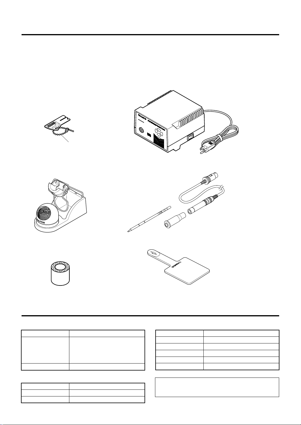
1. P ACKING LIST
Please check to make sure that all items listed below are
included in the FP-102 package.
FP-102 soldering station.................................1
FM-2021 connector assembly .....................1
Sleeve assembly ............................................ 1
Control card, with chain ..................................1
Control card
Card chain
Tip (not included)
Heat resistant pad...........................................1
Tip tray ............................................................1
Iron holder.......................................................1
Cleaning wire ..................................................1
Instruction manual ..........................................1
M
O
D
E
L
FP-102
7
.5
7
.0
8
.0
6
.5
FP-102 Soldering station
FM-2021 Connector assembly
Iron holder
Tip tray
2. SPECIFICA TIONS
● FP-102 soldering station
Power consumption
Temperature range
Temperature stability
● Station
Output
Dimensions(W × H × D)
Weight (w/o cord)
1
75 W
The four segment lights on the front
panel indicate the heat range selected
for the FP-102 (6.5 = ~650°F. [343°C];
7.0 = ~700°F. [371°C]; 7.5 = ~750°F.
[399°C]; 8.0 = ~800°F. [427°C]).
±9°F (±5°C) at idle temperature
24 V
120 × 93 × 140 mm (4.7 × 3.7 × 5.5 in.)
1,400 g (3.1 lb.)
Heat resistant pad
● Soldering iron
Power consumption
Tip to ground resistance
Tip to ground potential
Length, less cord
Weight, less cord
Length of cord
NOTE:
This product is protected against electrostatic discharge.
Specifications and design are subject to change without notice.
Sleeve assembly*
*Yellow, orange or blue sleeve
assembly is included.
70 W (24 V)
< 2 Ω
< 2 mV
188 mm (7.4 in.) with 2.4D tip
30 g (0.067 lb./1.07 oz.) with 2.4D tip
1.2 m (4 ft)
3.
W ARNINGS, CAUTIONS, NOTES AND EXAMPLES
Warnings, cautions and notes are placed at critical points in this manual to direct the
operator’s attention to significant items. They are defined as follows:
WARNING: Failure to comply with a WARNING may result in serious injury or
death.
CAUTION: Failure to comply with a CAUTION may result in injury to the
operator, or damage to the items involved. (Two examples are
given below.)
NOTE: A NOTE indicates a procedure or point that is important to the process being
described.
EXAMPLE: An EXAMPLE is given to demonstrate a particular procedure, point or
process.
CAUTION
When power is ON, the tip will be HOT (between 300-450°C. [~572-840°F.])
To avoid injury or damage to personnel and items in the work area, observe the
following:
● Do not touch the tip or the metal parts near the tip.
● Do not allow the tip to come close to, or touch, flammable materials.
● Inform others in the area that the unit is hot and should not be touched.
● Turn the power off when not in use, or left unattended.
● Turn the power off when connecting the FM-2021 or storing the FP-102.
● Do not remove or damage the bar code sticker.
CAUTION
To prevent accidents or damage to the FP-102, be sure to observe the following:
● Do not use the FP-102 for applications other than soldering.
● Do not allow the FP-102 to become wet, or use it with wet hands.
● Do not modify the FP-102.
● Use only genuine Hakko replacement parts.
● Do not bend or damage the control card. If the card does become damaged, do not force the
card into the station slot.
● Do not strike the iron against hard objects to remove excess solder. This may damage the
iron.
● Remove power and iron cords by holding the plug, not the wires.
● Be sure the work area is well ventilated. Soldering produces smoke.
2
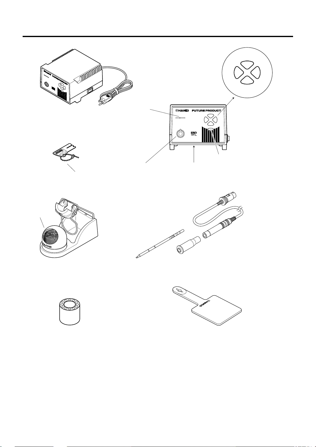
4. PART NAMES
blue
7.5
FP-102 Soldering station
Tip cleaner
MO
D
EL
FP-102
7
.5
7
.0
8
.0
6.5
Control card
Card chain
Card slot
Receptacle
Tip (not included)
yellow
®
MODEL
FP-102
7.5
8.07.0
6.5
The heat range selector button
Auto power shutoff switch
(on the bottom front of the case)
FM-2021 Connector assembly
6.5
green
red
8.07.0
Sleeve assembly
Iron holder
Tip tray
Heat resistant pad
3
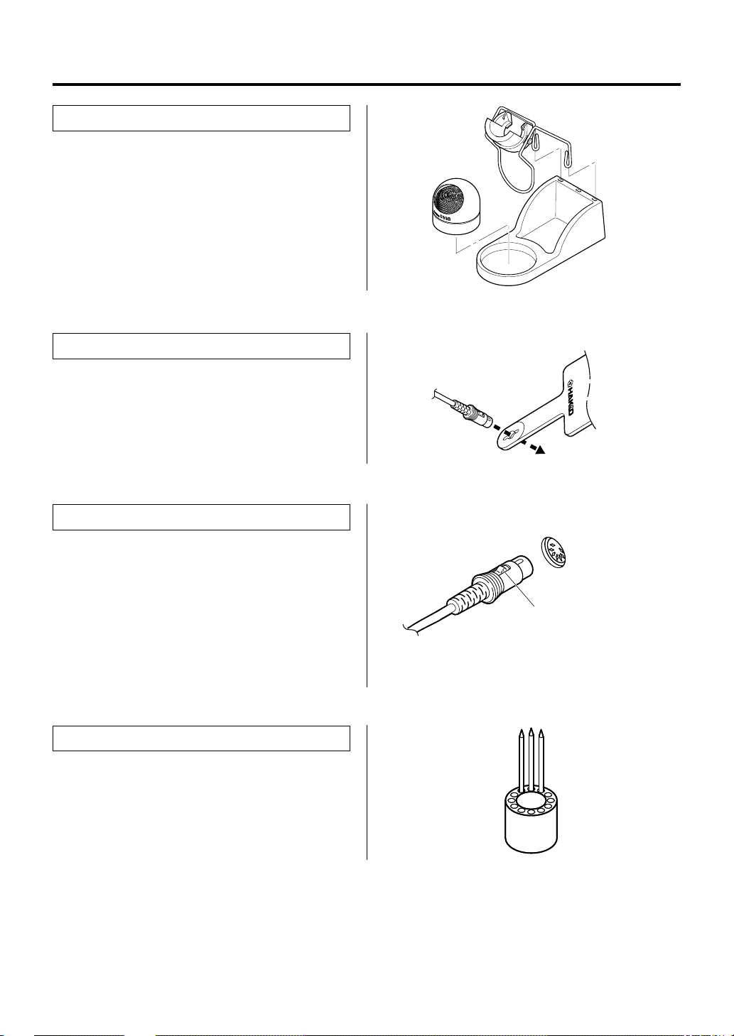
5. INITIAL SETUP
● Iron holder
Assemble as shown:
● Insert the holder assembly securely into
the Iron holder base.
● Connector cord
Pass the connector cord through the hole in the
heat resistant pad.
● Soldering station
1. Insert the connector cord into the receptacle
at the front of the station.
2. Plug the power cord into a grounded wall
socket. The FP-102 is protected against
electrostatic discharge and must be
grounded for full efficiency.
● Tip tray
Place spare tips in the tip tray.
Receptacle
Push the connector in as far as
it will go. When the plug clicks,
it is fully inserted.
4
Loading...