


®
Desoldering Tool
Instruction Manual
●
Thank you for purchasing the Hakko 472D desoldering tool with digital temperature display.
Please read this manual before operating the Hakko 472D. Keep this manual readily accessible for reference.
●
CAUTION
Before Plugging In!
REMOVE the pump securing screw (M4 × 25, red) from the bottom of the 472D station before using it. Leaving the screw in place will cause serious problems. Be sure to SAVE THIS SCREW!
REPLACE the pump securing screw (M4 × 25, red) into the bottom of the 472D station before transporting it. Leaving the screw out will cause serious problems.
TABLE OF CONTENTS |
|
PACKING LIST / SPECIFICATIONS .............................................. |
1 |
WARNINGS, CAUTIONS, NOTES AND EXAMPLES ................... |
2 |
PART NAMES ............................................................................... |
3 |
OPERATION .................................................................................. |
4 |
PARAMETER SETTING ................................................................ |
8 |
MAINTENANCE ............................................................................ |
9 |
REPLACEMENT PARTS ............................................................. |
12 |
ERROR MESSAGES ................................................................... |
14 |
BEFORE SERVICING ...... .......................................................... |
14 |
REPLACEMENT/OPTIONAL PARTS .......................................... |
15 |
PARTS LIST (IRON) .................................................................... |
16 |
PARTS LIST (STATION) .............................................................. |
17 |
WIRING DIAGRAM...................................................................... |
19 |
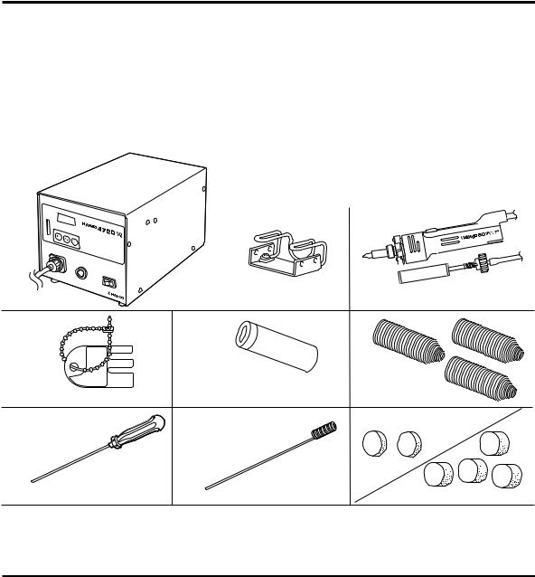
PACKING LIST
Please check to make sure that all the items listed below are included in the Hakko 472D package.
Station ............................................................. |
1 |
Desoldering iron (Hakko 807) ......................... |
1 |
Filter pipe [w/filter holder, spring filter & |
|
ceramic paper filter (L)] ................ |
1 |
Spring filter ...................................................... |
3 |
Ceramic paper filter (S) ................................... |
2 |
Ceramic paper filter (L) ................................... |
4 |
Cleaning pin for ø1.0 mm (0.04 in.) nozzle ..... |
1 |
Cleaning pin for heating element .................... |
1 |
Iron holder ....................................................... |
1 |
Instruction manual .......................................... |
1 |
Control card .................................................... |
1 |
Card chain ....................................................... |
1 |
Iron holder |
Desoldering iron (Hakko 807) |
Station
Control card/Card chain |
Filter pipe |
Spring filter |
|
|
Ceramic paper filter (S) |
Cleaning pin for heating element |
Cleaning pin for ø1.0 mm (0.04 in.) nozzle |
Ceramic paper filter (L) |
SPECIFICATIONS
Station |
Hakko 472D |
|
|
Power consumption |
120V AC, 110W |
|
|
Vacuum pressure |
80 KPa (600 mmHg)(24 in.Hg) |
|
|
Suction flow |
15 liters/min |
|
|
Nozzle to ground potential |
Under 2 m V |
|
|
Nozzle to ground resistance |
Under 2 Ω |
|
|
Outer dimensions (l × w × h) |
263 × 160 × 148 mm |
|
(10.4 × 6.3 × 5.8 in.) |
|
|
Weight (w/o cord) |
4.6 kg (10.14 lb.) |
|
|
Desoldering iron |
Hakko 807 |
|
|
Power consumption |
24V AC, 60W |
|
|
Temperature range |
350-450°C (662-842°F) |
|
|
Total length (w/o cord) |
205 mm (8.07 in.) |
|
|
Weight (w/o cord) |
Aprox.160 g (0.35 lb.) |
|
|
1

WARNINGS, CAUTIONS, NOTES AND EXAMPLES
Warnings, cautions and notes are placed at critical points in this manual to direct the operator’s attention to significant items. They are defined as follows:
 WARNING: Misuse may potentially cause death of, or serious injury to the user.
 CAUTION: Misuse may potentially cause injury to the user or physical damage to the objects involved.
For your own safety, be sure to comply with these precautions.
NOTE: A NOTE indicates a procedure or point that is important to the process being described.
EXAMPLE: An EXAMPLE is give to demonstrate a particular procedure, point or process.
 CAUTION
Remove the pump securing screws (M4×25 marked red) from the bottom of the station.
Failure to do so may result in serious problems. Be sure to save this screw.
When the power is on, the nozzle temperature will be between 350°C/662°F and 450°C/ 842°F.
Since mishandling may lead to burns or fire, be sure to comply with the following precautions.
●Do not touch the metallic parts near the nozzle, nearby plastic parts and the iron holder .
●Do not use the product near flammable items.
●Advise other people in the work area that the unit can reach a very high temperature and should be considered potentially dangerous.
●Turn the power off when no longer using the Hakko 472D or leaving it unattended.
●Before replacing parts or storing the unit, turn the power off and allow the unit to cool to room temperature.
To prevent accidents and failures, be sure to take the following precautions:
●Do not use the unit for applications other than desoldering.
●Do not rap the desoldering iron against the work bench to shake off residual solder, or otherwise subject the iron to severe shocks.
●Do not modify the unit.
●Use only genuine Hakko replacement parts.
●Do not wet the unit or use the unit with wet hands.
●Set the ceramic paper filter (S) for the filter retainer (station), and the ceramic paper filter (L) for the filter pipe (Iron).
●Maintain the desoldering gun and the station.
●While using the unit, don’t do anything which may cause bodily harm or physical damage.
2
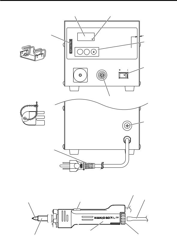
PART NAMES
● Station
Temperature display Heater lamp
Control card slot |
CAL POT |
|
Membrane sheet |
UP DOWN |
CAL |
Iron holder
VACUUM |
IRON |
POWER |
Power switch |
|
Vacuum outlet cap 
Receptacle
Fuse holder
Control card
Power cord
● Desoldering iron
|
|
Cord assembly |
Nozzle |
Button |
Hose |
|
|
|
|
|
|
|
|
|
|
|
|
|
|
|
|
|
|
|
|
|
|
|
|
|
|
|
|
|
|
|
|
|
|
|
|
|
|
|
|
|
|
|
|
|
|
|
|
|
|
|
|
|
|
|
|
|
|
Filter pipe (Inside housing) |
|
|
|
|
Back holder |
||||
|
|
|
|
|
|
|
|
|
|
|
||||||
Heating element (Inside pipe)
3
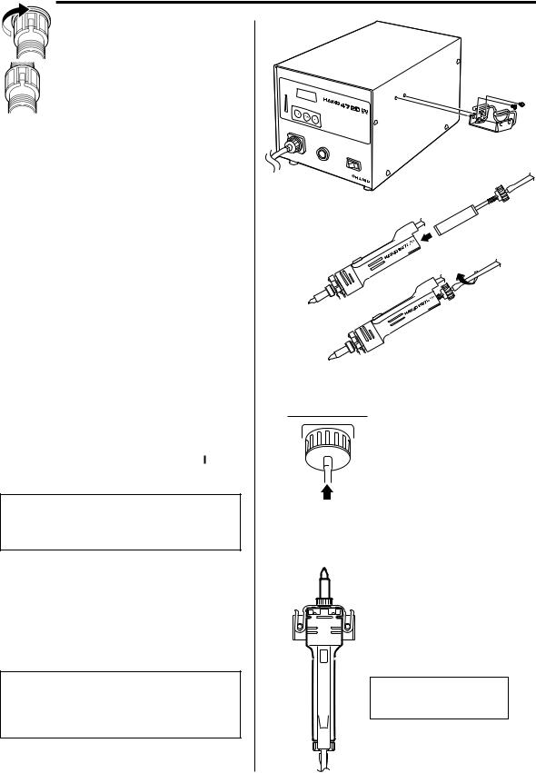
OPERATION
● Attach the iron holder.
Remove the iron holder mounting screws from the side of the station.
Attach the iron holder to the station. (Figure 1)
(The iron holder can be installed on the either the left or right side.)
● Attach the desoldering iron.
1.Insert the filter pipe (with a filter holder, spring filter and ceramic paper filter (L)) into the housing.
Push and turn the back holder clockwise. (Figure 2)
2.Connect the cord assembly of the Hakko 807 to the receptacle. (Figure 3)
3.Connect the hose to the vacuum outlet cap. (Figure 4)
4.Set the iron in the iron holder. (Figure 5)
5.Plug the power cord into the power supply
and turn the power switch to ON ( ).
 CAUTION:
Be sure the power switch is OFF ( ) before connecting the desoldering iron cord. Failure to do so may result in damage to circuit board.
● Desoldering
1. Set the temperature.
(Refer to P.6)
NOTE:
Always set the temperature as low as possible for the work being done.
The temperature can be adjusted between 350 – 450°C (662 – 842°F).
(Figure 1)
(Figure 2 )
VACUUM
Attach the hose securely over the vacuum outlet cap.
(Figure 4)
Insert the cord assembly by keying the plug to the key on the receptacle.
Secure the plug by turning it clockwise.
(Figure 3)
 CAUTION
When not in use, place the iron on the iron holder.
(Figure 5 ) Top view
4

OPERATION
2. Clean the tip of the nozzle.
Keep the tinned section of the nozzle clean and shiny by coating it with a small amount of solder.
If the tip of the nozzle is coated with oxide, the nozzle’s heat conductivity will be lowered. Coating the tip with a small amount of fresh solder ensures maximum heat conductivity.
NOTE:
The cleaner is not included.
3.Melt the solder.
•Apply the nozzle to the soldered part and melt the solder.
NOTE:
Never allow the nozzle to touch the board itself.
• Confirm that the solder is melted.
NOTE:
•To confirm that all the solder is melted, observe the inside of the hole and the backside of the P.W.B. If this is difficult to do, try slowly moving the lead with the nozzle if the lead moves, the solder is melted.
•Never move the lead by force.
If it doesn’t move easily, the solder is not yet fully melted.
4. Extract the solder.
After confirming that the solder is completely melted, extract the solder by pushing the button on the iron.
NOTE:
Never leave any solder remaining inside the hole in the P.W.B.
5. Problems during desoldering.
If solder remains, resolder the component and repeat the desoldering process.
Nozzle cleaner (Optional parts)
Wipe away any oxide or old solder from the nozzle using the hole in the center of the sponge.
Nozzle
P.W.B.
Solder
Lead
Slowly move the lead with the nozzle.
Extract the solder by slowly moving the lead back and forth with the tip of the nozzle.
5
 Loading...