


®
MODEL


 FM-2024
Instruction Manual
●
Thank you for purchasing the FM-2024 desoldering tool.
Please read this manual before operating the FM-2024.
Keep this manual readily accessible for reference.
●
 CAUTION
●The FM-2024 cannot function by itself. It must be connected to the Desolder Control Box (DCB), which in turn connects to the soldering station of choice, either FM-202 or FP-102.
●For detailed information on the FM-202 and the FP-102 soldering stations, refer to the instruction manual for the appropriate soldering station.
TABLE OF CONTENTS
1.PACKING LIST ………………………………………… 1
2.SPECIFICATIONS……………………………………… 1
3. WARNINGS, CAUTIONS AND NOTES …………… 2
4.PART NAMES ………………………………………… 3
5.OPERATION …………………………………………… 4
6.MAINTENANCE……………………………………… 10
7.TROUBLE SHOOTING GUIDE …………………… 14
8.PARTS LIST ………………………………………… 17
9.WIRING DIAGRAM ………………………………… 19
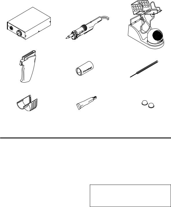
1. PACKING LIST Please check to make sure that all the items listed be- low are included:
Desolder control box (DCB) ............................ |
1 |
Desoldering tool .............................................. |
1 |
Iron holder ....................................................... |
1 |
Handle (for gun configuration)......................... |
1 |
Filter pipe assembly ........................................ |
1 |
Cleaning drill (for heating element).................. |
1 |
Nozzle remover................................................ |
1 |
Silicone grease................................................ |
1 |
Rubber foot ..................................................... |
2 |
Instruction manual........................................... |
1 |
DESOLDER |
CON |
|
|
TROL |
|
|
|
BOX
Desolder control box (DCB)
F24MV--27002W4
Desoldering tool
(Nozzle is not included)
Iron holder
Handle (for gun configuration) |
Filter pipe assembly |
Cleaning drill (for heating element) |
Nozzle remover |
Silicone grease |
Rubber foot |
2. SPECIFICATIONS
Desolder control box
Power consumption |
12 W |
Output |
24 V |
Vacuum generator |
Ejector type |
|
|
Vacuum pressure (max.) |
93 kPa (700 mmHg) (28 in. Hg) |
|
|
Suction flow |
28ℓ/min. |
Tip to ground potential |
< 2 mV |
|
|
Applied air pressure |
490 kPa (5.0 kgf/cm2) when in |
|
use (trigger or button is pressed) |
Compressed air |
1.62 c.f.m. (46ℓ/min.) |
consumption |
|
Outer dimension, less |
4.7 (W) × 1.8 (H) × 6.8 (D) in. |
cord |
(119 × 45 × 172 mm) |
Weight |
2.6 lb. (1.2 kg) |
|
|
Desoldering tool
Power consumption |
70 W (24 V) |
Temperature range |
650 - 840°F (350 - 450°C) |
Tip to ground potential |
< 2 mV |
|
|
Tip to ground resistance |
< 2 Ω |
Length, less cord |
7.09 in. (180 mm) |
|
|
Weight, less cord & hose |
0.14 lb. (65 g) |
|
|
Length of cord |
4 ft. (1.2 m) |
|
|
NOTE
The temperatures were measured using the Hakko 192 soldering tester.
This product is protected against electrostatic discharge. Specifications and design are subject to change without notice.
1
3. WARNINGS, CAUTIONS AND NOTES
 WARNING
In this instruction manual, “WARNING” and “CAUTION” are defined as follows.
WARNING: Misuse may potentially cause death of, or serious injury to the user.
CAUTION : Misuse may potentially cause injury to the user or physical damage to the objects involved.
For your safety, be sure to comply with these precautions.
Failure to do so may result in serious problems.
 CAUTION
When the power is on, the nozzle temperature is between 650°F/350°C and 840°F/450°C. Since mishandling may lead to burns or fire, be sure to comply with the following precautions.
●Do not touch the metal parts near the nozzle, nearby plastic parts, or the spring iron holder.
●Do not use the product near flammable items.
●Advise other people in the work area that the unit can reach a very high temperature and should be considered potentially dangerous.
●Turn the power off while taking breaks and when finished using the unit.
●Before replacing parts or storing the unit, turn the power off and allow the unit to cool to room temperature.
To prevent damage to the unit and ensure a safe working environment, be sure to comply with the following precautions.
Use only filtered air. Adjust the pressure to 490 to 686 kPa (5.0 to 7.0 kgf/cm2) while allowing air to flow by pulling the trigger.
●Do not use the unit for applications other than desoldering.
●Do not rap the desoldering tool against the work bench to shake off residual solder, or otherwise subject the iron to severe shocks.
●Do not modify the unit.
●Use only genuine HAKKO replacement parts.
●Do not wet the unit or use the unit when your hands are wet.
●Do not damage or bend the card. Never try to insert the bent card.
●When desoldering, ensure good ventilation for smoke.
●While using the unit, don’t do anything which may cause bodily harm or physical damage.
2
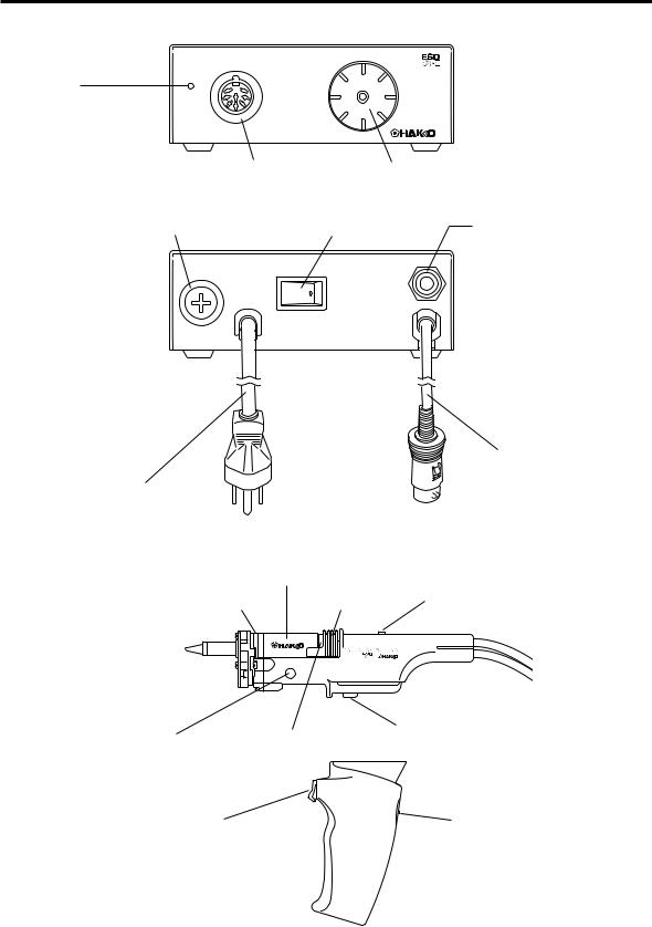
4. PART NAMES (Refer to p.17~18 for part nos.)
DCB <Front>
DESOLDER CONTROL BOX
Power lamp
Illuminated when the power switch is turned ON.
Receptacle |
Filter case cover |
Connect the FM-2024 to |
The ceramic paper filter is |
this receptacle. |
located inside. |
Fuse holder |
Power switch |
<Back>
Power code
MODEL FM-2024 |
Filter pipe |
|
|
Replace as a cartridge. |
|
|
Front holder |
Back holder |
|
|
FM-2024 |
|
|
24V-70W |
Union
External air inlet.
Connecting cord
Connect to FM-202 or
FP-102.
Filter pipe lock button
The filter pipe will be locked until this button is presssed.
|
|
Push button |
Nozzle unlock button |
Back holder bushing |
Suction start switch (when straight grip is used). |
Remove the nozzle from the |
|
|
grip while pressing this button. |
|
|
Trigger |
|
Slide button |
Suction start switch (when gun style handle is used).
To remove the gun handle, slide the button up to unlock it.
3
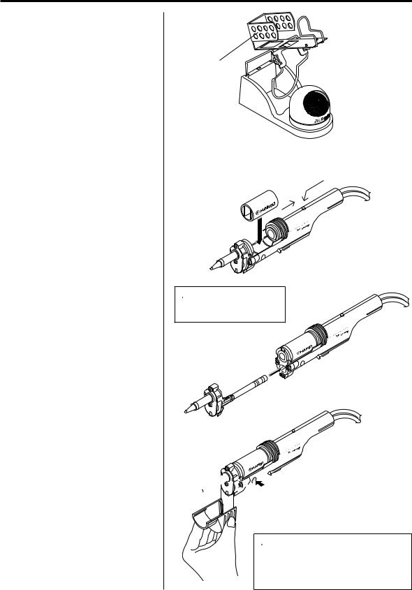
5. OPERATION
Assembling, connection and operation
1.Iron holder
2.Connecting and replacing
the filter pipe
Pull the back holder (A) until it locks, then insert the filter pipe with the opening to the nozzle side. Ensure that the outer surface of the filter pipe is even with the handle support. If the filter pipe is tilted, a leak may occur.
To replace the filter pipe, press back holder unlock button, pull the back holder to lock it, change the filter pipe, then lock the filter pipe.
Replace the filter pipe in the cartridge.
3. Attaching and replacing the nozzle
Insert the grip fully into the nozzle cartridge as shown in the illustration. Once the nozzle cartridge is inserted, it is locked automatically.
To replace the nozzle cartridge, insert the nozzle remover into the flange of the nozzle cartridge and pull.
Iron holder assembly
Iron holder
(B)
(A)
|
4 |
-202 |
|
FM |
-70W |
24V |
|
 CAUTION
The surface of the filter pipe may be very hot.
|
4 |
-202 |
|
FM |
-70W |
24V |
|
Attaching
Replacing
-2024 FM -70W 24V

 Push
Push

Nozzle remover
 CAUTION
The nozzle can be very hot. To attach or remove the nozzle cartridge, be sure to use the nozzle remover to preclude the possibility of breaking the grip or cartridge.
4

5. OPERATION
Press the nozzle unlock button (A) and remove the nozzle cartridge.
 CAUTION
The nozzle may be very hot.
The nozzle remover may be left mounted on the end of the straight grip when not in use to prevent it from being misplaced.
Connections
1.Connect the plug from the FM-2024 to the receptacle on the DCB, then connect the DCB to the soldering station as shown in the drawing.
2.Put the FM-2024 into the iron holder
To mount the FP-102 atop the DCB, attach two rubber feet, which come with the FP-102, to the bottom rear of the FP-102 to prevent the FP-102 from falling off.
3.Connect the hose from the FM-2024 to the filter case cover on the DCB.
5
DESOLDER CONTROL |
BOX |
FM-2024

 24V-70W

5 .6 .80
0  .7
.7  .57
.57
20 |
1P-F |
|
F24MV--27002W4
A
Not sensitive to vertical orientation
FM-2024 

 24V-70W

 CAUTION
The FP-102 is currently sold in the U.S. market.
7.5
FP-102
7.0 |
8.0 |
6.5
Fully insert |
Receptacle |
until the plug is |
|
clicked. |
|
Insert the plug until it stops, and then pull it without pressing the lock pin.
If this does not disconnect the plug from the receptacle, the plug is inserted properly.
Fully insert.
 Loading...