


HFU-09HA03/R2(DB)
HFU-12HA03/R2(DB)
HFU-18HA03/R2(DB)
No, 0010516188

Cautions
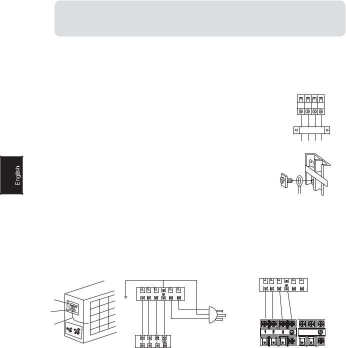
Disposal of the old air conditioner
Before disposing an old air conditioner that goes out of use, please make sure it's inoperative and safe. Unplug the air conditioner in order to avoid the risk of child entrapment.
It must be noticed that air conditioner system contains refrigerants, which require specialized waste disposal. The valuable materials contained in an air conditioner can be recycled
.Contact your local waste disposal center for proper disposal of an old air conditioner and contact your local authority or your dealer if you have any question. Please ensure that the pipework of your air conditioner does not get damaged prior to being picked up by the relevant waste disposal center, and contribute to environmental awareness by insisting on an appropriate, anti-pollution method of disposal.
Disposal of the packaging of your new air conditioner
Safety Instructions and Warnings
Before starting the air conditioner, read the information given in the User's Guide carefully. The User's Guide contains very important observations relating to the assembly, operation and maintenance of the air conditioner.
The manufacturer does not accept responsibility for any damages that may arise due to non-observation of the following instruction.
 Damaged air conditioners are not to be put into operation. In case of doubt, consult your supplier.
 Use of the air conditioner is to be carried out in strict compliance with the relative instructions set forth in the User's Guide.
 Installation shall be done by professional people, don't install unit by yourself.
 For the purpose of the safety,the air conditioner must be properly grounded in accordance with specifications.
All the packaging materials employed in the package of your new air conditioner may be disposed without any danger to the environment.
The cardboard box may be broken or cut into smaller pieces and given to a waste paper disposal service. The wrapping bag made of polyethylene and the polyethylene foam pads
All these valuable materials may be taken to a waste collecting center and used again after adequate recycling.
Consult your local authorities for the name and address of the waste materials collecting centers and waste paper disposal services nearest to your house.
 Always remember to unplug the air conditioner before openning inlet grill. Never unplug your air conditioner by pulling on the power cord. Always grip plug firmly and pull straight out from the outlet.
 All electrical repairs must be carried out by qualified electricians. Inadequate repairs may result in a major source of danger for the user of the air conditioner.
 Do not damage any parts of the air conditioner that carry refrigerant by piercing or performating the air conditioner's tubes with sharp or pointed items, crushing or twisting any tubes, or scraping the coatings off the surfaces. If the refrigerant spurts out and gets into eyes, it may result in serious eye injuries.
1

Cautions
 Do not obstruct or cover the ventilation grille of the air conditoner.Do not put fingers or any other things into the inlet/outlet and swing louver.
 Do not allow children to play with the air conditioner.In no case should children be allowed to sit on the outdoor unit.
Specifications
 The refrigerating circuit is leak-proof.
The machine is adaptive in following situation
1.Applicable ambient temperature range:
Indoor |
Maximum:D.B/W.B |
32oC/23oC |
Minimum:D.B/W.B |
18oC/14oC |
|
Cooling |
Maximum:D.B/W.B |
43oC/26oC |
Outdoor Maximum:D.B |
18oC |
|
Indoor |
Maximum:D.B |
27oC |
Maximum:D.B |
15oC |
|
Heating Outdoor Maximum:D.B/W.B |
24oC/18oC |
|
|
Minimum:D.B/W.B |
-7oC/-8oC |
2.If the power supply cord is damaged, it must be replaced by the manufacturer or its service agent or a similar qualified person.
3.If the fuse of indoor unit on PC board is broken,please change it with the type of
T.3.15A/ 250V. If the fuse of outdoor unit is broken, change it with the type of T.25A/250V.
4.The wiring method should be in line with the local wiring standard.
5.After installation, the power plug should be easily reached.
6.The waste battery should be disposed properly.
7.The appliance is not intended for use by young children or infirm persons without supervision.
8.Young children should be supervised to ensure that they do not play with the appliance.
9 .The distance between the indoor unit and the floor should be more than 2m.
10.Please employ the proper power plug, which fit into the power supply cord.
11 .The power plug and connecting cable must have acquired the local attestation.
2

Cautions
Safety Instruction
 Please read the following Safety Instructions carefully prior to use
 The instructions are classified into two levels, WARNING and CAUTION according to the seriousness of possible risks and damages as follows. Compliance to the instructions are strictly required for safety use.
Installation
 WARNING
Please call Sales/Service Shop for the Installation.
Do not attempt to install the air conditioner by yourself because improper works may cause electric shock, fire, water leakage.
Installation in a inadequate place may cause accidents. Do not install in the following place.
securely  CAUTION
Connect the earth |
Do not install in the |
cable. |
place where there is |
|
any possibility of |
|
inflammable gas |
|
leakage around the |
|
unit. |
earthing |
PROHIBITION |
|
Use fuse with specified capacity. Replacement with steel or copper wires are absolutely prohibited.
Do not get the unit |
Check proper |
exposed to vapor |
installation of the |
or oil steam. |
drainage |
STRICT
PROHIBITION ENFORCEMENT
Grounding wire should not be connected to that of gas pipeline, water pipeline, lighting arrester or telephone.
FUSE
COPPERWIRE
STEEL WIRE
3

Cautions
|
WARNING |
|
|
When abnormality such as burnt-small found, |
Use an exclusive power source with a |
||
immediately stop the operation button and |
circuit breaker |
|
|
contact sales shop. |
|
|
|
OFF |
STRICT |
|
|
|
ENFORCEMENT |
|
|
Connect power supply cord |
After installed, the unit shall be |
Do not use power supply cord |
|
to the outlet completely |
tested for electric leakage. |
extended or connected in halfway |
|
STRICT |
|
STRICT |
PROHIBITION |
ENFORCEMENT |
|
ENFORCEMENT |
|
|
|
||
Do not use power supply cord |
Take care not to damage |
Do not insert objects into the air |
|
in a bundle. |
the power supply cord. |
inlet or outlet. |
|
PROHIBITION |
|
PROHIBITION |
PROHIBITION |
Do not start or stop the |
Do not channel the air flow directly |
Do not try to repair or reconstruct |
|
operation by disconnecting |
at people, especially at infants or |
by yourself. |
|
the power supply cord and so on. |
the aged. |
|
|
PROHIBITION |
|
PROHIBITION |
|
Do not use for the purpose of storage of food, art work, precise equipment, breeding, or cultivation.
 CAUTION
Take fresh air occasionally especially |
Do not operate the switch with |
when gas appliance is running at the |
wet hand. |
same time. |
|

 PROHIBITION
Do not install the unit near a fireplace or other heating apparatus.
PROHIBITION
Do not place animals or plants in the direct path of the air flow
STRICT
ENFORCEMENT
Check good condition of the installation stand
PROHIBITION
Do not place any objects on or climb on the unit.
PROHIBITION
Do not pour water onto the unit for cleaning
PROHIBITION
Do not place flower vase or water containers on the top of the unit.
PROHIBITION |
PROHIBITION |
PROHIBITION |
4

Parts and Functions
Indoor unit
1.OUTLET
2.CONTROL PANEL
3.INLET
4.FILTER (inside)
5.OUTLET
Outdoor unit
HFU-09HA03/R2(DB)
HFU-12HA03/R2(DB)
HFU-18HA03/R2(DB)
OUTLET |
CONNECTING PIPING AND ELECTRICAL WIRING |
INLET |
DRAIN HOSE |
5

3DUWV DQG )XQFWLRQV
 &$87,21
%HIRUH RSHQLQJ WKH IURQW JULOOH EH VXUH WR VWRS WKH RSHUDWLRQ DQG WXUQ WKH EUHDNHU 2)) 'R QRW WRXFK WKH PHWDO SDUWV RQ WKH LQVLGH RI WKH LQGRRU XQLW DV LW PD\ UHVXOW LQ LQMXU\
5HFHLYHU
 6LJQDOV DUH UHFHLYHG IURP WKH UHPRWH FRQWUROOHU KHUH
 8SRQ UHFHLYLQJ D VLJQDO WKHUH LV D UHFHLYLQJ VRXQG
$LU RXWOHW VHOHFWLRQ VZLWFK
 7KLV VHWWLQJ EORZV DLU IURP XSSHU RXWOHW RQO\
 7KLV VHWWLQJ DXWRPDWLFDOO\ GHFLGHV D EORZ
  SDWWHUQ GHSHQGLQJ RQ PRGH DQG FRQGLWLRQV
 7KLV VHWWLQJ LV
UHFRPPHQGHG
21 2)) EXWWRQ
 3XVK RQFH WR VWDUW RSHUDWLRQ
SXVK RQFH DJDLQ WR VWRS LW
 2SHUDWLRQ LV VHW WR $872 DLU
IORZ LV VHW WR $872 )$1
8VH ZKHQ UHPRWH FRQWUROOHU LV |
$LU RXWOHW |
QRW DYDLODEOH |
VHOHFWLRQ |
,QGRRU WHPSHUDWXUH VHQVRU
|
6HQVHV WKH DLU WHPSHUDWXUH DURXQG WKH XQLW |
2SHUDWLQJ |
6LWXDWLRQ |
|
%ORZLQJ SDWWHUQ |
||
$LU IORZ VHOHFWLRQ |
|
||||||
PRGH |
|
||||||
|
|
|
|||||
|
|
|
|
||||
|
0DNH DLU IORZ VHOHFWLRQ DFFRUGLQJ WR ZKDW VXLWV \RX |
|
:KHQ WKH URRP KDV |
|
6R WKDW DLU GRHV QRW FRPH |
||
|
|
|
|
|
|
||
|
:KHQ VHWWLQJ WKH DLU RXWOHW VHOHFWLRQ |
|
EHFRPH IXOO\ FRRO |
LQWR GLUHFW FRQWDFW ZLWK |
|||
|
|
|
|
SHRSOH DLU LV EORZQ XSSHU DLU |
|||
|
VZLWFK WR |
|
|
|
RXWOHW URRP WHPSHUDWXUH LV |
||
|
&RRO |
|
|
HTXDOLVHG |
|||
|
5HJDUGOHVV RI WKH RSHUDWLQJ PRGH RU VLWXDWLRQ DLU |
PRGH |
|
|
|
||
|
|
|
|||||
|
EORZV IURP WKH XSSHU DLU RXWOHW |
|
$W VWDUW RI RSHUDWLRQ |
|
|
||
|
8VH WKLV VZLWFK ZKHQ \RX GR QRW ZDQW DLU FRPLQJ |
|
RU RWKHU WLPHV ZKHQ |
|
$LU LV EORZQ IURP WKH XSSHU DQG |
||
|
RXW RI WKH ORZHU DLU RXWOHW :KLOH VOHHSLQJ HWF |
|
WKH URRP LV QRW IXOO\ |
|
ORZHU DLU RXWOHWV IRU KLJK VSHHG |
||
|
|
|
|
|
FRROHG |
|
FRROLQJ GXULQJ &RRO PRGH DQG |
|
|
|
|
|
|
|
|
|
|
|
|
|
|
|
IRU ILOOLQJ WKH URRP ZLWK ZDUP |
|
|
|
|
|
|
||
|
|
|
|
|
$W WLPHV RWKHU WKDQ |
DLU GXULQJ +HDW PRGH |
|
|
:KHQ VHWWLQJ WKH DLU RXWOHW VHOHFWLRQ |
|
EHORZ 1RUPDO |
|
|
||
|
|
WLPH |
|
|
|||
|
|
|
|
||||
|
VZLWFK WR |
|
|
+HDW |
|
|
|
|
|
|
|
|
|
|
|
|
|
|
|
PRGH |
|
|
|
|
$LU FRQGLWLRQHU DXWRPDWLFDOO\ GHFLGHV WKH |
$W VWDUW RU ZKHQ DLU |
6R WKDW DLU GRHV QRW FRPH LQWR |
||||
|
|
||||||
|
DSSURSULDWH EORZLQJ SDWWHUQ GHSHQGLQJ RQ WKH |
|
WHPSHUDWXUH LV ORZ |
|
GLUHFW FRQWDFW ZLWK SHRSOH $LU |
||
|
RSHUDWLQJ PRGH VLWXDWLRQ |
|
|
|
LV EORZQ XSSHU DLU RXWOHW |
||
'XULQJ 'U\ DQG )DQ PRGH VR WKDW FROG DLU GRHV QRW FRPH LQWR GLUHFW FRQWDFW ZLWK SHRSOH DLU LV EORZQ XSSHU
DLU RXWOHW
5

Parts and Functions
Remote Controller
1.TIMER
Used to select TIMER ON, TIMER OFF, TIMER ON-OFF
2.HOUR
Used to set clock and timer setting.
3.CLOCK
Used to set correct time.
4. MODE
Used to select AUTO, COOL, DRY, FAN and HEAT operation.
Note:
1.The following functions and related displays are not available for all models: Display of humidifying and atmosphere humidity.
2.There is health display with the remote controller in this type, but without health function.
5.ON/OFF
Used for unit start and stop.
6.SWING
Used to adjust the up/down air flow direction.
7.TEMP.
Used to select your desired temperature.
8.TIMER ON display
9.SLEEP display
10.FAN SPEED display
Remote controller:
LOW |
MED |
HI |
AUTO |
11.SWING UP/DOWN display
12.MODE display
Operation |
Remote |
mode |
controller |
AUTO |
|
COOL
DRY
FAN
HEAT
13.SIGNAL SENDING display
14.TEMP. display
Remote controller: to display the TEMP. setting.
15.CLOCK display
16.TIMER OFF display
17.FAN
Used to select fan speed: LO,MED,HI,AUTO 18. SET
Used to confirm timer and clock settings.
19.SLEEP
Used to select sleep mode.
20.RESET
When the remote controller appears abnormal, use a sharp pointed item to press this button
to reset the remote controller to normal condition.
21.LOCK
Used to lock buttons and LCD display. If pressed, the other buttons will be disabled and the lock condition display appears.
Press it once again, lock will be canceled and lock condition display disappears.
22.LOCK display
23.POWER/SOFT
7

Parts and Functions

 Clock Set
When unit is started for the first time and after replacing batteries in remote controller, clock should be adjusted as follows:
1. Press CLOCK button,"AM" or "PM" flashes.
2. Press or to set correct time. Each press will increase or decrease 1 min. If the button is kept depressed, time will change quickly.
3. After time setting is confirmed, press SET, "AM" or "PM" stop flashing, while clock starts working.

 Remote controller's operation
 When in use, put the signal transmission head directly to the receiver hole on the indoor unit.
 The distance between the signal transmission head and the receiver hole should be within 7 m without any obstacle as well.
 Don't throw or knock the remoter controller.
 When electronic-started type fluorescent lamp or change-over type fluorescent lamp or wireless telephone is installed in the room, the receiver is apt to be disturbed in receiving the signals, so the distance to the indoor unit should be shorter.
Loading of the battery
Load the batteries as illustrated right 2 R-03 (7#) batteries
Remove the battery cover:
Slightly press"  "area and push down the cover as illustrated.
Load the battery:
Be sure that the loading is in line with the "+" / "-". request as illustrated on the bottom of the case. Put on the cover again.
Confirmation indicator:
After pressing power ON/OFF, if no display, reload the batteries.
Note:
Full display or unclear display during operation indicates the batteries have been used up. Please change batteries.
Used two new same-typed batteries when loading.
If the remote controller can't run normally during operation, please remove the batteries and reload several minutes later.
Hint:
Remove the batteries in case unit won't be in usage for a long period. If there are any display after taking-out, just need to press reset key.
8

Operation
Auto Operation
Remote controller
 4
4
5
1. Unit start
Press ON/OFF on the indoor unit, or press ON/OFFon the remote controller, unit starts.
Previous operation status appears on LED display , and set the operation mode.
2.Select operation mode
Press MODE button. For each press, operation mode changes as follows:
Remote controller:
AUTO COOL DRY FAN HEAT
Then Select Auto operation
3.Select temp.setting
Press TEMP. button
 Every time the button is pressed, temp.setting increase 1oC,if kept depressed, it will increase rapidly
 Every time the button is pressed, temp.setting decrease 1oC,if kept depressed, it will decrease rapidly
Select a desired temperature.
4.Fan speed selection
Press FAN button. For each press, fan speed changes as follows:
Remote controller:
LOW MED HI AUTO
Air conditioner is running under displayed wind speed When FAN is set to AUTO, the air conditioner automatically adjusts the fan speed according to room temperature.
5.Unit stop
Press ON/OFF button, the unit stops.
About AUTO mode
In AUTO run mode, the air conditioner will automatically select cooling or heating operation mode according to room temperature.
9
Operation
Cool Operation
Remote controller
1.Unit start
Press ON/OFF on the indoor unit, or press ON/OFFon the remote controller, unit starts.
Previous operation status appears on LED display.
2.Select operation mode
Press MODE button. For each press, operation mode changes as follows:
Remote controller:
AUTO COOL DRY FAN HEAT
Then Select Cool operation
3.Select temp.setting
Press TEMP. button
 Every time the button is pressed, temp.setting increase 1oC,if kept depressed, it will increase rapidly
 Every time the button is pressed, temp.setting decrease 1oC,if kept depressed, it will decrease rapidly
Select a desired temperature.
4.Fan speed selection
Press FAN button. For each press, fan speed changes as follows:
Remote controller:
LOW MED HI AUTO
Air conditioner is running under displayed wind speed When FAN is set to AUTO, the air conditioner automatically adjusts the fan speed according to room temperature.
5.Unit stop
Press ON/OFF button, the unit stops.
10

Operation
DRY Operation
Remote controller
COOL operation starts when room |
|
temp.is higher than temp.setting. |
Ultra-low air flow |
|
Temp.setting+2oC
Temp.setting
On reaching temp.setting +2oC unit will run in mild DRY mode.
1.Unit start
Press ON/OFF on the indoor unit, or press ON/OFFon the remote controller, unit starts.
Previous operation status appears on LED display.
2.Select operation mode
Press MODE button. For each press, operation mode changes as follows:
Remote controller:
AUTO COOL DRY FAN HEAT
Then Select DRY operation
3.Select temp.setting
Press TEMP. button
 Every time the button is pressed, temp.setting increase 1oC,if kept depressed, it will increase rapidly
 Every time the button is pressed, temp.setting decrease 1oC,if kept depressed, it will decrease rapidly
Select a desired temperature.
4.Fan speed selection
Press FAN button. For each press, fan speed changes as follows:
Remote controller:
LOW MED HI AUTO
Air conditioner is running under displayed fan speed. In DRY mode, when room temperature becomes lower than temp.setting+2oC,unit will run intermittently at LOW speed regardless of FAN setting.
5.Unit stop
Press ON/OFF button, the unit stops.
11

Operation
FAN Operation
|
1. Unit start |
Remote controller |
Press ON/OFF on the indoor unit, or press ON/OFFon |
|
the remote controller, unit starts. |
|
Previous operation status appears on LED display. |
2.Select operation mode
Press MODE button. For each press, operation mode changes as follows:
Remote controller:
AUTO COOL DRY FAN HEAT
Then Select FAN operation
3.Fan speed selection
Press FAN button. For each press, fan speed changes as
follows:
Remote controller:
LOW MED HI
4.Unit stop
Press ON/OFF button, the unit stops.
About FAN operation
In FAN operation mode, the unit will not operate in COOL or HEAT mode but only in FAN mode. AUTO is not available in FAN mode. And temp. setting is disabled. In FAN mode, SLEEP operation is not available.
12

Operation
HEAT Operation
Remote controller
Regarding the ambient temperature display during the heating operation
In defrosting,the indoor temperature value displayed may be reduced due to the dropping of cooling air of the evaporator of indoor unit under cooling mode. It is normal phenomenon.
1.Unit start
Press ON/OFF on the indoor unit, or press ON/OFFon the remote controller, unit starts.
Previous operation status appears on LED display.
2.Select operation mode
Press MODE button. For each press, operation mode changes as follows:
Remote controller:
AUTO COOL DRY FAN HEAT
Then Select HEAT operation
3.Select temp.setting
Press TEMP. button
 Every time the button is pressed, temp.setting increase 1oC,if kept depressed, it will increase rapidly
 Every time the button is pressed, temp.setting decrease 1oC,if kept depressed, it will decrease rapidly
Select a desired temperature.
4.Fan speed selection
Press FAN button. For each press, fan speed changes as follows:
Remote controller:
LOW MED HI AUTO
Air conditioner is running under displayed wind speed
IN HEAT mode, warm air will blow out after a short period of the time due to cold-draft prevention function.
When FAN is set to AUTO, the air conditioner automatically adjusts the fan speed according to room temperature.
5.Unit stop
Press ON/OFF button, the unit stops.
13

Operation
Adjusting the Air Flow Direction
You can adjust the air flow direction to |
Notes on flap angles |
increase your comfort |
When SWING is selected, the flap swinging range depends |
|
|
|
on the operation mode.(See the figure.) |
Adjusting the flap
COOL/DRY
HEAT
NOTE
 Unless [SWING] is selected, you should set the flap at a near-horizontal angle in HEAT mode and at a upward position in COOL or DRY mode to obtain the best performance.
CAUTION
 Do not try to adjust the flap by hand.
 When adjusting by hand, the mechanism may not operate properly or condensation may drip from air outlets
ATTENTION
 When adjusting the flap by hand, turn off the unit, and use the remote controller to restart the unit.
Adjusting the louver
Hold the knob and move the louver.
(You will find a knob on the left-side and the right-side blades
ATTENTION
 Be careful when adjusting the louver. Inside the air outlet, a fan is rotating at a high speed.
14

Operation
SLEEP Operation
Before going to bed , you can simply press the SLEEP button and unit will operation in SLEEP mode and bring you a sound sleep.
Use of SLEEP function
After the unit starts, set the operation status, then press SLEEP button before which the clock must be adjusted and time being set.
Operation Mode
1. In COOL,DRY mode
3 hours after SLEEP mode starts, temperature will become 1oC higher than temperature setting. After another 3 hours temperature rises by 1oC further. The unit will run for further 2 hours then stops. Temperature is higher than temperature setting so that room temperature won't be too low for your sleep.
Remote controller
SLEEP operation starts |
SLEEP operation stops |
|||
|
|
|
$SSUR[ KUV |
|
|
|
|
|
|
|
KU |
|
Rises 1oC |
|
|
|
|
|
|
KU |
Rises 1oC |
|||
|
|
|
|
|
Temperature setting |
Unit stop |
|||
In COOL,DRY mode
2. In HEAT mode
3 hours after SLEEP mode starts, temperature will become 1oC lower than temperature setting. After another 3 hours temperature decrease by 1oC further. The unit will run for further 2 hours then stops. Temperature is lower than temperature setting so that room temperature won't be too high for your sleep.
7HPSHUDWXUH VHWWLQJ 8QLW VWRS
KU |
|
R |
& |
|
|
'HFUHDVHV |
|
|
KU |
'HFUHDVHV R& |
|
|
|
||
|
|
KU |
5LVHV R& |
6/((3 |
|
$SSUR[ KUV |
|
|
|
6/((3 |
|
RSHUDWLRQ VWDUWV |
|
RSHUDWLRQ VWRSV |
|
,Q +($7 PRGH
,Q $872 PRGH
The unit operates in corresponding sleep SLEEP mode adapted to the automatically selected operation mode.
4.In FAN mode
It has timing off function.
5.The sleep time can be adjusted within the range of 1-8 hours.
Push the SLEEP button. The remote controller will display " ", and display the timing off and detail off time in the timing off setting area.
Push the time adjusting button to adjust the detail sleep time.
6. If the sleep time in cooling, dehumidifying and heating run is less than 8 hours
Within the set sleep time, the conditioner will run as per the procedure described in 1 and 2. It will be switched off automatically when the sleep time is expired.
15

Operation
Timer On/Off Operation
Set clock correctly before starting TIMER operation.
1. After unit starts, select your desired operation mode.
Operation mode will be displayed on LCD
Remote controller
2. Timer mode selection
Press TMIER button to change TIMER mode. Every time' the button pressed, display changes as follows:
Remote controller:


 BLANK
BLANK
TIMER ON TIMER OFF |
TIMER ON-OFF |
Then select your desired TIMER mode (TIMER ON or
TIMER OFF). "  "or "
"or "  "will flash.
3.Time setting
Press HOUR
 button.
Every time the button is pressed, time setting increases 1 min, if kept depressed, it will increase rapidly.
 Every time the button is pressed, time setting decreases 1 min, if kept depressed, it will decrease rapidly.
It can be adjusted within 24 hours.
4.Confirming your setting
After setting correct time, press SET button to confirm "  "or"
"or"  "on the remote controller stops flashing. Time displayed: Unit starts or stops at x hour x min.
(TIMER ON or TIMER OFF).
5.Cancel TIMER mode
Just press TIMER button several times until TIMER mode disappears.
Hints:
After replacing batteries or a power failure happens, time setting should be reset. Remote controller possesses memory function, when use TIMER mode next time,just press SET button after mode selecting if time setting is the same as previous one.
16

Operation
TIMER On-Off Operation
Set clock correctly before starting TIMER operation.
1.After unit starts, select your desired operation mode Operation mode will be displayed on LCD.
Remote Controller |
2. Timer mode selection |
|
|
|
|
Press TIMER button to change TIMER mode. Every time |
|
|
|
the button is pressed, display changes as follows: |
|
|
|
Remote controller: |
|
|
|
|
BLANK |
|
|
TIMER ON TIMER OFF |
TIMER ON-OFF |
|
Then select your desired TIMER mode (TIMER ON - OFF). |
||
|
" |
"will flash. |
|
3.Time setting
Press HOUR
 button.
Every time the button is pressed, time setting
increases 1 min, if kept depressed, it will increase rapidly.  Every time the button is pressed, time setting
decreases 1 min, if kept depressed, it will decrease rapidlly. It can be adjusted within 24 hours.
4.Timer confirming for TIMER ON
After setting correct time, press TIMER button to confirm "  " on the remote controller stops flashing.
"  " starts flashing.
Time displayed: Unit starts or stops at x hour x min.
5.Time setting for TIMER OFF
Just press HOUR button ,follow the same procedure in "Time setting for TIMER ON"
6.Time confirming for TIMER OFF
After time setting,press SET button to confirm. "  " on the remote controller stops blinking. Time displayed:Unit stops at x hour x min.
To cancel TIMER mode
Just press TIMER button several times until TIMER mode disappears.
According to the Time setting sequence of TIMER ON or TIMER OFF, either Start-Stop or Stop-Start can be achieved.
17

Operation
POWER/SOFT Operation
POWER Operation
When you need rapid heating or cooling, you can use this funciton.
Selecting of POWER operation
Press POWER/SOFT button. Every time the button is pressed,display
changes as |
BLANK |
|
follows: |
||
SOFT |
||
POWER |
Stop the display at 


In POWER operation status:
In HEAT or COOL mode, fan speed automatically runs in HI mode for 15 min then returns to original status setting.
To cancel POWER operation
Press POWER/SOFT button twice ,POWER/SOFT disappears.
SOFT Operation
You can use this function when silence is needed for rest or reading.
Selecting of SOFT operation
Press POWER/SOFT button. Every time the button is pressed,display |
||
changes as |
BLANK |
|
follows: |
||
POWER SOFT |
||
Stop the display at 
In SOFT operation mode, fan speed automatically takes"LOW"
To cancel SOFT operation
Press POWER/SOFT button twice ,POWER/SOFT disappears.
Hints:
During POWER operation, in rapid HEAT or COOL mode, the room will show inhomogeneous temperature distribution.
Long period SOFT operation will cause effect of not too cool or not too warm.
18

Operation
EMERGENCY OPERATION AND TEST OPERATION
EMERGENCY OPERATION |
|
Carry out this operation only when the remote |
|
controller is defective or lost. |
POWER TIMER RUN |
 Unit start
When the emergency operation switch is
pressed, a sound you can hear, which ON/OFF means the start of this operation.
Follow the requirements below.
EMERGENCY SWITCH
Room |
Designated |
Timer |
Air flow |
Operation |
Anion |
|
temperature |
temperature |
mode |
speed |
mode |
||
|
||||||
|
|
|
|
|
|
|
>23oC |
26oC |
None |
AUTO |
COOL |
None |
|
R& |
23oC |
None |
AUTO |
HEAT |
None |
Unit stop (to cancel emergency operation)
Press the emergency switch and hear a sound, the unit stops.
TEST OPERATION
Use this switch in the test operation when the room temperature is less 16oC, do not it in the normal operation.
Unit start
Continue to press the test operation switch for more than 5 seconds. After you hear the "BI" sound twice, release your finger from the switch, the test operation starts and the air conditioner starts with the air flow speed setting "Hi".
Unit stop(to cancel test operation)
POWER TIMER RUN
ON/OFF
TEST SWITCH
Push the test run switch or operate with remote controller to cancel the test run.
If you use the remote controller to cancel the test run, the conditioner will then run as per the working mode displayed on the remote controller.
19
Operation hints
Remote monitoring
The control board of the indoor unit reserves the communication port for remote control. If you install the peripheral equipment according to the manual of the matching remote control detector, it can realize the computer management or remote monitoring of the conditioner. Please refer to the manual of the " Conditioner remote control detector" for the details
Power failure resume(please set and apply as necessary)
With setting of power failure resume, if sudden power failure occurs, the unit will resume original operation when power is supplied again.
Setting method
With ON of remote controller (except TIMER and FAN),repeatedly press SLEEP button 10 times in 5 seconds, after 4 Beep from the buzzer, the unit comes into power failure resume mode.
To cancel:
press SLEEP button continuously 10 times in 5 seconds, the buzzer sounds Beep twice and power failure resume function is canceled.
Note:
When sudden power failure happens during unit operation in power failure resume mode,if the air conditioner is not desired for use in a long period, please shut off the power supply in case that the unit automatially resume operation when power is re-supplied, or press ON/OFF to turn off the unit when power resumes.
20

Maintenance
Cleaning of the unit
Turn off the power switch Do not touch with wet hand |
Do not clean with hot |
|
|
water or solvent |
|
|
|
|
|
|
|
Take off the air inlet grill
First switch off the power supply, take off the
screw cap, loosen the screw with cross screwdriver.
Clean the filter
Use water or vacuum cleaner to remove dust. If it is too dirt, clean with detergent or neutral soap water.
Rinsing with fresh water, dry the filter and re-assemble.
Caution:
Do not wash filter in hot water above 40oC, which will damage the filter.
Do carefully wipe the filter.
Clean the indoor(outdoor) unit
Clean with warm cloth or neutral detergent, then wipe away moisture with dry cloth. Do not use too hot water(above 40oC), which will cause discoloration or deformation. Do not use pesticide or other chemical detergents.
21

0DLQWHQDQFH
0DLQWHQDQFH DW WKH HQG RI DSSOLFDWLRQ VHDVRQ
2Q D ILQH GD\ XQLW VKDOO EH VWDUWHG DQG RSHUDWH LQ )$1 PRGH IRU DERXW KDOI D GD\ XQLW WKH LQVLGH RI WKH XQLW EHFRPHV WKRURXJKO\ GU\
7XUQ RII WKH XQLW RSHUDWLRQ VZLWFK DQG SRZHU RQ RII 2WKHUZLVH WKHUH ZLOO EH VRPH HOHFWULFLW\ FRQVXPSWLRQ HYHQ WKH XQLW LV LQ VWRS VWDWXV
&OHDQ WKH ILOWHU DQG LQGRRU RXWGRRU XQLW FRYHU WKH XQLWV ZHOO
0DLQWHQDQFH EHIRUH EHJLQQLQJ RI DSSOLFDWLRQ VHDVRQ
&KHFN WKHUH DUH QR REVWDFOHV LQ WKH DLU LQOHW DQG RXWOHW WR DYRLG LPSDLULQJ RI ZRUNLQJ HIILFLHQF\
3OHDVH GR DWWDFK WKH DLU ILOWHU WR HQVXUH WKH HOHFWURVWDWLF ILOWHUV QRW VRLOHG 2WKHUZLVH GLUW ZLOO FRPH LQWR DQG GDPDJH WKH XQLW RU EULQJ IDLOXUHV

Trouble shooting
Before asking for service, check the following first.
|
Phenomenon |
Cause or check points |
|
|
|
|
|
|
|
|
The system does not restart |
When unit is stopped, it won't restart |
|
|
|
immediately. |
immediately until 3 minutes have elapsed |
|
|
|
|
to protect the system. |
|
|
|
|
When the electric plug is pulled out and |
|
|
|
|
reinserted, the protection circuit will work |
|
|
|
|
for 3 minutes to protect the air conditioner. |
|
|
|
|
|
|
|
|
|
During unit operation or at stop, a swishing |
|
|
|
Noise is heard: |
or gurgling noise may be heard. At first 2-3 |
|
|
|
minutes after unit start, this noise is more |
|
|
|
|
|
|
||
Normal |
noticeable. (This noise is generated by |
|
|
|
refrigerant flowing in the system.) |
|
|
||
Performance |
|
|
||
During unit operation, a cracking noise may |
|
|
||
inspection |
|
|
||
be heard. This noise is generated by the |
|
|
||
|
|
|
|
|
|
|
casing expanding or shrinking because of |
|
|
|
|
temperature changes. |
|
|
|
|
Should there be a big noise from air flow in |
|
|
|
|
unit operation, air filter may be too dirty. |
|
|
 This is because the system circulates smells Smells are generated. from the interior air such as the smell of
furniture, cigarettes.
 During COOL or DRY operation, indoor unit Mist or steam are blown out. may blow out mist. This is due to the sudden
cooling of indoor air.
 Is power plug inserted?
Multiple Does not work at all.  Is there a power failure? check
 Is fuse blown out?
Poor cooling |
Is the air filter dirty? Normally it should be |
|
cleaned every 15 days. |
||
|
||
|
Are there any obstacles before inlet and outlet? |
|
|
Is temperature set correctly? |
|
|
Are there some doors or windows left open? |
|
|
Is there any direct sunlight through the |
|
|
window during the cooling operation?(Use |
|
|
curtain) |
|
|
Are there too much heat sources or too many |
|
|
people in the room during cooling operation? |
23

Installation Manual of Room Air Conditioner
more than 10 cm
morethan10 cm
mor e t han 10 cm
|
|
|
|
m |
|
|
|
|
|
|
|
c |
|
|
|
|
|
|
|
|
0 |
|
|
|
|
|
|
|
0 |
|
|
|
|
|
|
|
|
1 |
|
|
|
|
|
|
|
|
n |
|
|
|
|
|
|
|
a |
|
|
|
|
|
|
|
|
th |
|
|
|
|
|
|
|
|
re |
|
|
|
Figure.1 |
|||
|
o |
|
|
|
||||
|
m |
|
|
|
||||
|
|
|
|
|
|
|
|
|
|
|
|
|
|
|
|
|
|
|
|
|
|
|
|
|
|
|
|
|
|
|
|
|
|
|
|
|
|
|
|
|
|
|
|
|
Figure.2
Figure.3
Installation of indoor unit
selection of installation place

 Place where it is easy to route drainage pipe and outdoor piping.

 Place, away from heat source and with less direct sunlight.

 Place where cool and warm air could be delivered evently to every corner of the room.

 Place near power supply socket.Leave enough space around the unit.

 Place, robust not causing vibration, where the body can be supported sufficiently.

 To prevent interference, place it at least 1m away from other electric machines, such as TV set, radio.
Installation

 According to the dimension of the Figure 2 shown nail two cement steel nails on the wall keep 2-3mm out, then hang the back of the unit on them.

 There must be no gap between the indoor unit and wall.

 Remove the front panel,then use two fastening screws to fix the unit on the floor. As Figure 3 shown.

 Once refrigerant piping and drain piping connections are complete,fill the gap of the through hole with putty.

 Attach the front panel and front grille in their orginal positions once all connections are complete.
Installation of outdoor unit
|
selection of installation place |
more |
|
Place strong enough to support the unit and will |
|
|
|
|
|
not cause vibration and noise. |
|
|
Place where discharged wind and noise does not |
|
|
|
|
|
cause a nuisance to the neighbors. |
|

 Place where is less affected by rain or direct sunlight and is sufficiently ventilated,or to install a shield.

 Place with enough space for smooth air flow.
than |
10 |
cm |
|
||
|
|
|
|
60 |
cm |
|
than |
|
|
more |
|
|
|
|
|
|
|
|
10 |
cm |
|
than |
|
|
more |
|
|
|
|
|
|
more |
than |
|
|
|
10 |
cm |
|
|
|
||
|
|
|
Figure.4
24

Installation Manual of Room Air Conditioner
Tool necessary
1.Screw driver 2.Hacksaw
3.70mm dia. hole core drill 4.Spanner(dia.17,27mm) 5.Spanner(14,17,27mm) 6.Pipe cutter
7.Flaring tool 8.Knife 9.Nipper
10.Gas leakage detector or soap water
11.Measuring tape 12.Reamer 13.Refrigerant oil
Standard accessories
Following parts shall be field supplied
Mark |
Part name |
AAdhensive tape
BPipe clip
C Connecting hose
D Insulation material
EDrain hose
No. Shape and description |
QTY |
Remote controller |
1 |
Drain hose |
1 |
Plastic cap |
4 |
Drain-elbow |
1 |
Self-tapping screw |
4 |
Rubber pad |
4 |
dry battery #7 |
2 |
256
|
|
|
|
|
|
|
|
|
|
|
|
|
140 |
|
|
500 |
|
|
140 |
|
|
||||
|
|
|
|
|
|
|
|
|
|
|
|
|
 319.5
319.5
113.5 |
583 |
113.5 |
HFU-09HA03/R2(DB) HFU-12HA03/R2(DB)
HFU-18HA03/R2(DB)
Fixing of the unit
1. Position of the wall hole
Wall hole should be decided according to installation place and piping direction.(refer to installation drawings).
2. Making a wall hole
Drill a hole of 120x70mm dia. with a little slope towards outside.
Indoor side |
Outdoor side |
Wall hole |
Thickness |
|
of wall |
(Cross section of wall hole)
25

Installation Manual of Room Air Conditioner
3. Piping connection Connecting method
Apply refrigerant oil at half union and flare nut.
To bent a pipe, give the roundness as large as possible not to crash the pipe.
When connecting pipe, hold the pipe center to center then screw nut on by hand, refer to Fig. Be careful not to let foreign matters, such as sands enter the pipe.
Forced fastening without careful centering may damage the threads and cause a leakage of gas.
Pipe Diameter |
Fastening torque |
|
|
|
|
Liquid side 6.35mm(1/4") |
18N.m |
|
|
|
|
Gas side 9.52mm(3/8") |
42N.m |
|
|
|
|
Gas side 12.7mm(1/2") |
55N.m |
|
|
|
|
Piping connection of the indoor unit
1.Arrangement of piping and drainage pipe Remove the cover before working.
Cut away, with a hammer or a saw, the lid for piping according to piping direction.
insulation material
Drain hose
Copper tube
Connecting electric cable for indoor and outdoor unit
According to the piping method, connect the piping on indoor unit with union of connection pipe. Arrange the piping as per the wall hole and bind drain hose connecting electric cable and piping together with polyethylene tape.
Insert the bound piping connecting electric cable and drain hose through wall hole to connect with outdoor unit.
2.Arrangement drain hose
Drain hose shall be placed in under place.
There should be a slope when arrange drain hose. Avoid up and down waves in drain hose. If humidity is high, drain pipe(especially in room and indoor unit) must be covered with installation material.
26

Installation Manual of Room Air Conditioner
3.Piping connection of the outdoor unit Connecting the connecting pipe and inlet and outlet liquid pipe according to the piping method
Purging Method:(For R410A) |
Liquid Side |
Gas Side |
6.35mm(1/4") |
9.52mm(3/8") |
|
|
|
|
|
|
12.7mm(1/2") |
Detach the service port's cap of 3-way valve, the |
2-way valve |
3-way valve |
valve rod's cap for 2-way valve and 3-way's, connect |
|
|
|
|
|
the service port into the projection of charge hose |
|
Gaugemanifold(for R410A) |
(low) for gaugemanifold. Then connect the projection |
|
Anti countercurrent joint |
of charge hose (center) for gaugemanifold into |
|
|
|
|
|
vacuum pump. |
|
|
|
Tube(for R410A) |
Vacuum pump(for R410A) |
Open the handle at low in gaugemanifold, operate
vacuum pump. If the scale-moves of gause (low) |
|
reach vacuum condition in a moment, check |
again. |
Vacuumize for over 15min. And check the level gauge which should read -0.1 MPa (-76 cm Hg) at low pressure side. After the completion of vacuumizing, close the handle 'Lo' in gaugemanifold and stop the operation of the vacuum pump.
Check the condition of the scale and hold it for 1-2min.
If the scale-moves back in spite of tightening, make |
|
flaring work again, the return to the beginning of |
. |

 Open
Open 


 Close
Close
Open the valve rod for the 2-way valve to an angle of
anticlockwise 90 degrees. |
2-way valve |
3-way valve |
|
Service port |
|||
After 6 seconds, close the 2-way valve and make |
o |
||
90ofor 6 sec. |
|||
|
Open |
|
90
the inspection of gas leakage.
In case of gas leakage, tighten
parts of pipe connection. If
No gas leakage?
leakage stops, then proceed steps.
Detach the charge hose from the service port, open 2-way valve and 3-way. Turn the valve rod anticlockwise until hitting lightly.
If it does not stop gas leakage, discharge whole refrigerants from the service port. After flaring work again and vacuumize, fill up prescribed refrigerant from the gas cylinder
|
3-way valve |
Liquid Side |
Gas Side |
|
2-way valve |
6.35mm(1/4") |
9.52mm(3/8") |
||
|
||||
|
|
|
12.7mm(1/2") |
|
|
|
3-way valve |
|
|
|
|
2-way valve |
|
To prevent the gas leakage, turn the service port's |
|
|
HFU-09HA03/R2(DB) |
|
cap, the valve rod's cap for 2-way valve and 3-way's |
|
3-way valve |
||
2-way valve |
HFU-12HA03/R2(DB) |
|||
a little more than the point where the torque increases |
||||
|
HFU-18HA03/R2(DB) |
|||
|
|
|||
suddenly. |
|
|
|
|
|
|
Valve rod cap |
||
After attaching the each caps, check the gas leakage |
Service port cap |
Valve rod cap |
|
|
|
|
|
||
around the caps. |
|
|
|
|
CAUTION: |
|
|
|
|
1.If the refrigerant of the air conditioner leaks, it is necessary to |
2.Please do not let other cooling medium, except specified one |
|||
discharge all the refrigerant. Vacuumize first, then charge the liquid |
(R410A), |
|
|
|
refrigerant into air conditioner according to the amount marked on |
or air enter into the cooling circulation system. Otherwise, there will be |
|||
the name plate. |
abnormal high pressure in the system to make it crack and lead to |
|||
|
personal injuries. |
|
|
|
27
,QVWDOODWLRQ 0DQXDO RI 5RRP $LU &RQGLWLRQHU
1RWH :KHQ DGGLWLRQDO UHIULJHUDQW LV QHFHVVDU\ ILUVW SXUJH DLU RXW RI FRQQHFWLQJ SLSH E\ H[WHUQDO JDV WKHQ GULYH RXW WKH H[FHVVLYH UHIULJHUDQW E\ SXUJLQJ PHWKRG %UDQG QHZ XQLW LV FKDUJHG J PRUH UHIULJHUDQW WKDQ VSHF 7KLV LV RQO\ IRU ILUVW LQVWDOODWLRQ WR SXUJH DLU LQ WKH LQGRRU XQLW DQG FRQQHFWLQJ SLSH :KHQ SLSLQJ LV ORQJHU WKDQ P FKDQJH DGGLWLRQDO UHIULJHUDQW VSHFLILHG LQ WKLV OLVW
3LSH OHQJWK |
|
P |
P |
P |
|
|
|
|
|
|
|
5HIULJHUDQW FKDUJH J |
|
|
|
|
|
|
|
|
|||
|
|
|
|
|
|
(OHFWULF ZLULQJ 1RWH
 (OHFWULF ZLULQJ PXVW EH GRQH E\ TXDOLILHG SHUVRQ
 8VH FRSSHU ZLUH RQO\
  7KH SDUDPHWHU RI WKH FRQQHFWLQJ FDEOH LV + 51 ) RU + 51 )
PRG * PP PRG * PP
:LULQJ RI LQGRRU XQLW
 ,QVHUW WKH FDEOH IURP RXWVLGH WKH ZDOO KROH ZKHUH SLSLQJ DOUHDG\ H[LVW
 3XOO LW RXW IURP IURQW
 /RRVH WHUPLQDO VFUHZ DQG LQVHUW FDEOH HQG IXOO\ LQWR WHUPLQDO EORFN WKHQ WLJKWHQ LW
 3XOO WKH FDEOH JHQWO\ WR PDNH VXUH LW LV WLJKW
  5HSODFH FRYHU DIWHU ZLULQJ
,QGRRU XQLW |
,QGRRU XQLW |
|
|
|
|
|
1 / & |
1 / |
1 / & |
1 / |
|
7HUPLQDO EORFN
:LUH FOLS |
32:(5 3/8* |
|
:LUH ORRS |
^ |
|
SRZHU |
||
|
||
|
1 / |
|
2XWGRRU XQLW |
2XWGRRU XQLW |
|
+)8 +$5 '% |
+)8 +$5 '% |
|
|
+)8 +$5 '%
:LULQJ RI RXWGRRU XQLW
 ,QVHUW WKH FDEOH IURP LQVLGH WKH ZDOO KROH ZKHUH SLSLQJ DOUHDG\ H[LVW
 3XOO LW RXW IURP IURQW
 /RRVH WHUPLQDO VFUHZ DQG LQVHUW FDEOH HQG IXOO\ LQWR WHUPLQDO EORFN WKHQ WLJKWHQ LW
 3XOO WKH FDEOH JHQWO\ WR PDNH VXUH LW LV WLJKW
  5HSODFH FRYHU DIWHU ZLULQJ
1RWH
 :KHQ FRQQHFWLQJ LQGRRU DQG RXWGRRU ZLUH FKHFN WKH QXPEHU RQ LQGRRU DQG RXWGRRU WHUPLQDO EORFNV 7HUPLQDOV RI VDPH QXPEHU DQG VDPH FRORU VKDOO EH FRQQHFWHG E\ WKH VDPH ZLUH
  ,QFRUUHFW ZLULQJ PD\ GDPDJH DLU FRQGLWLRQHUV FRQWURO RU FDXVH RSHUDWLRQ IDLOXUH

,QVWDOODWLRQ 0DQXDO RI 5RRP $LU &RQGLWLRQHU
2WKHUV
3RZHU VXSSO\
$LU FRQGLWLRQHU PXVW XVH DQ H[FOXVLYH OLQH RYHU $ DQG WKHUH LV QRW SRZHU SOXJ
ZLWK WKLV W\SH + 51 ) + 51 ) * PP PRG WKH W\SH RI SRZHU VXSSO\ ZLUH LV +) 99 * PP PRG
:KHQ LQVWDOODWLRQ DLU FRQGLWLRQHU LQ D ZHW SODFH WU\ WR XVH D FLUFXLW EUHDNHU DJDLQVW FXUUHQW OHDNDJH
)RU LQVWDOODWLRQ LQ RWKHU SODFHV XVH FLUFXLW EUHDNHU DV IRU DV SRVVLEOH3LSLQJ FXWWLQJ DQG IODULQJ
%H VXUH WR FDUU\ RXW GHEXUULQJ DIWHU FXWWLQJ ZLWK D SLSH FXWWHU ,QVHUW IODULQJ WRRO WR PDNH D IODUH
$ |
|
)RU FRROLQJ PHGLXP 5 $ |
|
|
|
|
)ODUH WRRO IRU 5 $ |
&RQYHQWLRQDO IODUH WRRO |
|
|
|
&OXWFK W\SH |
FOXWFK W\SH 5LJLG W\SH :LQJ QXW W\SH ,PSHULDO W\SH |
|
|
)ODUH WRROLQJ GLH |
a PP |
a PP |
a PP |
|
|
|
|
|
&XW SLSH |
5HPRYH EXUV |
|
|
|
,QVHUW WKH IODUH QXW
&RUUHFW |
,QFRUUHFW |
)ODUH SLSH
/HDQ 'DPDJH RI IODUH &UDFN |
3DUWLDO 7RR RXWVLGH |
,QVWDOODWLRQ LQVSHFWLRQ DQG WHVW UXQ 3OHDVH RSHUDWH XQLW DFFRUGLQJ WR WKLV 0DQXDO ,WHPV WR EH FKHFNHG GXULQJ WHVW UXQ 3OHDVH PDGH D LQ 
 $UH WKHUH DQ\ JDV OHDNDJH"

 +RZ LV LQVXODWLRQ DW SLSLQJ FRQQHFWLRQ FDUULHG RXW"

 $UH HOHFWULF ZLUHV RI LQGRRU DQG RXWGRRU XQLW ILUPO\ LQVHUWHG LQWR WHUPLQDO EORFN"

 ,V HOHFWULF ZLULQJ RI LQGRRU DQG RXWGRRU VHFXUHO\ IL[HG"

 ,V GUDLQDJH VHFXUHO\ FDUULHG RXW"

 ,V HDUWK OLQH JURXQGLQJ VHFXUHO\ FRQQHFWHG"

 ,V SRZHU VXSSO\ YROWDJH DELGHG E\ WKH FRGH"

 ,V WKHUH DQ\ QRLVH"

 ,V FRQWURO GLVSOD\ QRUPDO"

 ,V FRROLQJ RSHUDWLRQ QRUPDO"
 ,V URRP WHPS UHJXODWRU QRUPDO"
 Loading...