


 Loading...
DOC342.53.80488
TU5200
03/2017, Edition 3
User Manual

|
Table of Contents |
Specifications.............................................................................................................. |
3 |
General information.................................................................................................. |
4 |
Safety information ........................................................................................................ |
4 |
Use of hazard information .................................................................................... |
4 |
Precautionary labels ............................................................................................. |
5 |
Class 2 laser product ............................................................................................ |
5 |
RFID module ........................................................................................................ |
6 |
Safety information for RFID modules ............................................................ |
6 |
FCC conformance for RFID ........................................................................... |
7 |
Certification ........................................................................................................... |
7 |
Product overview ......................................................................................................... |
8 |
Product components .................................................................................................... |
8 |
Installation..................................................................................................................... |
9 |
Installation guidelines .................................................................................................. |
9 |
Connect to external devices (optional) ........................................................................ |
9 |
User interface and navigation............................................................................ |
10 |
Startup........................................................................................................................... |
11 |
Operation..................................................................................................................... |
12 |
Configuration ............................................................................................................. |
12 |
Configure the instrument settings ....................................................................... |
12 |
Change the language .................................................................................. |
13 |
Add operator IDs ................................................................................................ |
13 |
Configure an operator RFID tag (optional) .................................................. |
14 |
Add sample IDs .................................................................................................. |
14 |
Import sample IDs (optional) ....................................................................... |
14 |
Configure the measurement settings .................................................................. |
15 |
Set the acceptance range ................................................................................... |
15 |
Set up a LAN connection .................................................................................... |
16 |
Connect to an FTP server or Netdrive ......................................................... |
16 |
Connect to a network printer ....................................................................... |
17 |
Connect to an sc controller .......................................................................... |
17 |
Measurement ............................................................................................................. |
18 |
Sample collection ............................................................................................... |
18 |
Prevent vial contamination ................................................................................. |
18 |
Prepare a sample vial ......................................................................................... |
19 |
Put the vial in the instrument .............................................................................. |
20 |
Measure the sample ........................................................................................... |
21 |
Compare process and laboratory measurements .............................................. |
21 |
Collect a grab sample .................................................................................. |
21 |
Compare measurements with RFID ............................................................ |
21 |
Compare measurements with Link2SC ....................................................... |
22 |
Show the recorded data ............................................................................................. |
24 |
Show the instrument information ............................................................................... |
25 |
Calibration................................................................................................................... |
26 |
Configure the calibration settings .............................................................................. |
26 |
1

Table of Contents |
|
Calibrate the instrument ............................................................................................. |
26 |
Verification.................................................................................................................. |
28 |
Configure the verification settings .............................................................................. |
28 |
Do a calibration verification ........................................................................................ |
28 |
Maintenance............................................................................................................... |
28 |
Clean spills ................................................................................................................ |
29 |
Clean the instrument .................................................................................................. |
29 |
Clean a sample vial ................................................................................................... |
29 |
Clean the vial compartment ....................................................................................... |
30 |
Troubleshooting....................................................................................................... |
30 |
Remove air bubbles from the sample ........................................................................ |
34 |
Condensation ............................................................................................................. |
34 |
Replacement parts and accessories............................................................... |
34 |
2

Specifications
Specifications are subject to change without notice.
Specification |
Details |
Measurement method |
Nephelometry with the scattered light collected at a 90° angle to the incident light |
|
and 360° around the sample vial. |
|
|
Primary compliance method |
EPA approved Hach Method 102581 |
Dimensions (W x D x H) |
41 x 28 x 12.5 cm (16 x 11 x 7.7 in.) |
|
|
Weight |
2.37 kg (5.23 lb) |
|
|
Enclosure |
IP20 |
|
|
Protection class |
Instrument: III; Power supply: II |
|
|
Pollution degree |
2 |
|
|
Installation category |
II |
|
|
Power requirements |
Instrument: 15 VDC, 2 A; Power supply: 100 to 240 VAC, 50/60 Hz |
|
|
Operating temperature |
10 to 40 °C (50 to 104 °F) |
|
|
Storage temperature |
–30 to 60 °C (–22 to 140 °F) |
|
|
Humidity |
5 to 95% relative humidity, non-condensing |
|
|
Display |
17.8 mm (7 in.) color touch screen |
|
|
Laser |
Class 2 laser product: Contains a non user-serviceable class 2 laser. |
|
|
Optical light source |
650 nm, maximum 0.43 mW |
|
|
Measurement units |
NTU, FNU, TE/F, FTU, EBC, mg/L, mNTU2 or mFNU |
Range |
0 to 700 NTU, FNU, TE/F, FTU; 0 to 100 mg/L; 0 to 175 EBC |
|
|
Accuracy |
± 2% of reading plus 0.01 NTU from 0 to 40 NTU |
|
± 10% of reading from 40 to 700 NTU based on Formazin primary standard at |
|
25 °C (77 °F) |
|
|
Linearity |
Better than 1% for 0 to 40 NTU on Formazin at 25 °C (77 °F) |
|
|
Precision |
< 40 NTU: 0.002 NTU or 1% (the larger value); > 40 NTU: 3.5% based on |
|
Formazin primary standard at 25 °C (77 °F) |
|
|
Stray light |
< 0.01 NTU |
|
|
Calibration options |
StablCal®: 1-point calibration (20 NTU) for 0 to 40 NTU measurement range; 2- |
|
point calibration (20 and 600 NTU) for 0 to 700 NTU (full) measurement range |
|
Formazin: 2-point calibration (20 NTU and dilution water) for 0 to 40 NTU |
|
measurement range; 3-point calibration (20 NTU, 600 NTU and dilution water) for |
|
0 to 700 NTU (full) measurement range |
|
Degrees: 3-point calibration (20 and 100 mg/L and dilution water) for 0 to 100 mg/L |
|
(full) measurement range |
|
SDVB: 3-point calibration (20 NTU, 600 NTU and dilution water) for 0 to 700 NTU |
|
(full) measurement range |
|
Custom: 2- to 6-point custom calibration for a measurement range of 0 NTU to the |
|
highest calibration point. |
|
|
1 http://www.hach.com
2 1 mNTU = 0.001 NTU
English 3
Specification |
Details |
Verification options |
Glass verification rod (secondary turbidity standard) < 0.1 NTU, StablCal or |
|
Formazin (0.1 to 40 NTU) |
|
|
Verification (RFID or |
Process and laboratory measurements are compared with RFID or Link2SC for |
Link2SC®) |
verification of the measurement value. |
Certifications |
CE compliant; US FDA accession number: 1420493-xxx. This product complies |
|
with IEC/EN 60825-1 and to 21 CFR 1040.10 in accordance with Laser Notice No. |
|
50. Australian RCM. |
|
|
Warranty |
1 year (EU: 2 years) |
|
|
General information
In no event will the manufacturer be liable for direct, indirect, special, incidental or consequential damages resulting from any defect or omission in this manual. The manufacturer reserves the right to make changes in this manual and the products it describes at any time, without notice or obligation. Revised editions are found on the manufacturer’s website.
Safety information
N O T I C E
The manufacturer is not responsible for any damages due to misapplication or misuse of this product including, without limitation, direct, incidental and consequential damages, and disclaims such damages to the full extent permitted under applicable law. The user is solely responsible to identify critical application risks and install appropriate mechanisms to protect processes during a possible equipment malfunction.
Please read this entire manual before unpacking, setting up or operating this equipment. Pay attention to all danger and caution statements. Failure to do so could result in serious injury to the operator or damage to the equipment.
Make sure that the protection provided by this equipment is not impaired. Do not use or install this equipment in any manner other than that specified in this manual.
Use of hazard information
 D A N G E R
Indicates a potentially or imminently hazardous situation which, if not avoided, will result in death or serious injury.
 W A R N I N G
Indicates a potentially or imminently hazardous situation which, if not avoided, could result in death or serious injury.
 C A U T I O N
Indicates a potentially hazardous situation that may result in minor or moderate injury.
N O T I C E
Indicates a situation which, if not avoided, may cause damage to the instrument. Information that requires special emphasis.
4 English
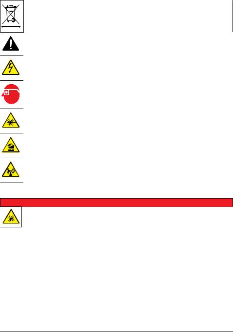
Precautionary labels
Read all labels and tags attached to the instrument. Personal injury or damage to the instrument could occur if not observed. A symbol on the instrument is referenced in the manual with a precautionary statement.
Electrical equipment marked with this symbol may not be disposed of in European domestic or public disposal systems. Return old or end-of-life equipment to the manufacturer for disposal at no charge to the user.
This symbol, if noted on the instrument, references the instruction manual for operation and/or safety information.
This symbol indicates that a risk of electrical shock and/or electrocution exists.
This symbol indicates the need for protective eye wear.
This symbol indicates a laser device is used in the equipment.
This symbol identifies a risk of chemical harm and indicates that only individuals qualified and trained to work with chemicals should handle chemicals or perform maintenance on chemical delivery systems associated with the equipment.
This symbol indicates radio waves.
Class 2 laser product
 D A N G E R
Personal injury hazard. Never remove covers from the instrument. This is a laser-based instrument and the user risks injury if exposed to the laser.
English 5
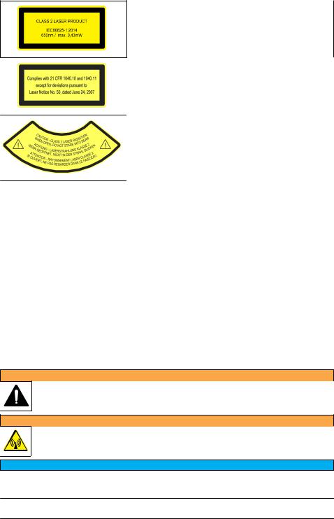
Class 2 laser product, IEC60825-1:2014, 650 nm, maximum 0.43 mW
Location: Rear of the instrument.
Conforms to U.S. regulations 21 CFR 1040.10 and 1040.11 in accordance with Laser Notice No. 50.
Location: Rear of the instrument.
Caution—Class 2 laser radiation when the lid is open. Do not look into the laser beam.
Location: Top of the vial compartment.
This instrument is a Class 2 Laser product. There is only visible laser radiation when the instrument is defective and when the instrument lid is open. This product complies with EN 61010-1, "Safety Requirements for Electrical Equipment for Measurement, Control and Laboratory Use" and with IEC/EN 60825-1, "Safety of Laser Products" and with 21 CFR 1040.10 in accordance with Laser Notice No. 50. Refer to the labels on the instrument that supply laser information.
RFID module
Instruments with the optional RFID module receive and transmit information and data. The RFID module operates with a frequency of 13.56 MHz.
RFID technology is a radio application. Radio applications are subject to national conditions of authorization. The use of instruments with the optional RFID module is currently permitted in the regions that follow:
EU (European Union) countries, EFTA (European Free Trade Association) countries, Turkey, Serbia, Macedonia, Australia, Canada, US, Chile, Ecuador, Venezuela, Mexico, Brazil, South Africa, India, Singapore, Argentina, Columbia, Peru and Panama
The use of instruments with the optional RFID module outside of the above-mentioned regions can violate national laws. The manufacturer reserves the right also to get authorization in other countries. In case of doubt, contact the manufacturer.
Safety information for RFID modules
 W A R N I N G
Multiple hazards. Do not disassemble the instrument for maintenance. If the internal components must be cleaned or repaired, contact the manufacturer.
 W A R N I N G
Electromagnetic radiation hazard. Do not use the instrument in dangerous environments.
N O T I C E
This instrument is sensitive to electromagnetic and electromechanical interference. These interferences can have an effect on the analysis performance of this instrument. Do not put this instrument near equipment that can cause interference.
6 English

Obey the safety information that follows to operate the instrument in accordance with local, regional and national requirements.
•Do not operate the instrument in hospitals and equivalent establishments or near medical equipment, such as pace makers or hearing aids.
•Do not operate the instrument near highly flammable substances, such as fuels, highly flammable chemicals and explosives.
•Do not operate the instrument near combustible gases, vapors or dust.
•Keep the instrument away from strong vibration or shock.
•The instrument can cause interference in immediate proximity to televisions, radios and computers.
•The warranty does not cover improper use or wear.
FCC conformance for RFID
This instrument may contain a registered radio frequency identification device (RFID). Refer to Table 1 for the Federal Communications Commission (FCC) registration information.
Table 1 |
Registration information |
|
|
|
|
Parameter |
|
Value |
FCC identification number (FCC ID) |
|
YUH-QR15HL |
|
|
|
IC |
|
9278A-QR15HL |
|
|
|
Frequency |
|
13.56 MHz |
|
|
|
Certification
Canadian Radio Interference-Causing Equipment Regulation, IECS-003, Class A: Supporting test records reside with the manufacturer.
This Class A digital apparatus meets all requirements of the Canadian Interference-Causing Equipment Regulations.
Cet appareil numérique de classe A répond à toutes les exigences de la réglementation canadienne sur les équipements provoquant des interférences.
FCC Part 15, Class "A" Limits
Supporting test records reside with the manufacturer. The device complies with Part 15 of the FCC Rules. Operation is subject to the following conditions:
1.The equipment may not cause harmful interference.
2.The equipment must accept any interference received, including interference that may cause undesired operation.
Changes or modifications to this equipment not expressly approved by the party responsible for compliance could void the user's authority to operate the equipment. This equipment has been tested and found to comply with the limits for a Class A digital device, pursuant to Part 15 of the FCC rules. These limits are designed to provide reasonable protection against harmful interference when the equipment is operated in a commercial environment. This equipment generates, uses and can radiate radio frequency energy and, if not installed and used in accordance with the instruction manual, may cause harmful interference to radio communications. Operation of this equipment in a residential area is likely to cause harmful interference, in which case the user will be required to correct the interference at their expense. The following techniques can be used to reduce interference problems:
1.Disconnect the equipment from its power source to verify that it is or is not the source of the interference.
2.If the equipment is connected to the same outlet as the device experiencing interference, connect the equipment to a different outlet.
3.Move the equipment away from the device receiving the interference.
English 7
4.Reposition the receiving antenna for the device receiving the interference.
5.Try combinations of the above.
Product overview
The TU5200 turbidimeter measures low turbidity mostly in finished drinking water applications. This laboratory instrument is factory calibrated and measures scattered light at an angle of 90° in a 360° radius around the axis of the incident light beam. Use the touch screen to operate the instrument.
Refer to Figure 1.
An optional RFID module is available. Figure 1 shows the RFID module. The RFID module lets process and laboratory turbidity measurements be easily compared.
Videos on how to install, operate and do maintenance and troubleshooting on the TU5200 turbidimeter are available on the TU5 Series Turbidimeters playlist at http://www.youtube.com/user/hachcompany.
For the accessories, refer to Replacement parts and accessories on page 34.
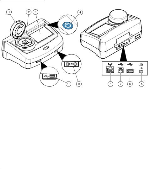
Figure 1 Product overview
1 |
Lid |
6 |
USB port type A |
|
|
|
|
2 |
Vial compartment |
7 |
USB port type B |
3 |
Display |
8 |
Ethernet port for LAN connection |
|
|
|
|
4 |
Power button |
9 |
RFID module indicator (optional) |
|
|
|
|
5 |
Power supply connection |
10 USB port type A |
|
Product components
Make sure that all components have been received. Refer to Figure 2. If any items are missing or damaged, contact the manufacturer or a sales representative immediately.
8 English

Figure 2 Product components
1 |
TU5200 |
4 |
Power supply with adapters |
|
|
|
|
2 |
StablCal kit, sealed vials with RFID (10, 20 and |
5 |
Dust cover |
|
600 NTU) |
|
|
3 |
Sample vials |
6 |
Vial stand |
|
|
|
|
Installation
 C A U T I O N
Multiple hazards. Only qualified personnel must conduct the tasks described in this section of the document.
This instrument is rated for an altitude of 3100 m (10,710 ft) maximum. Use of this instrument at an altitude higher than 3100 m can slightly increase the potential for the electrical insulation to break down, which can result in an electric shock hazard. The manufacturer recommends that users with concerns contact technical support.
Installation guidelines
Install the instrument:
•On a level surface
•In a clean, dry, well ventilated, temperature controlled location
•In a location with minimum vibrations that has no direct exposure to sunlight
•In a location where there is sufficient clearance around it to make connections and to do maintenance tasks
•In a location where the power button and power cord are visible and easily accessible
Connect to external devices (optional)
The instrument has three USB 1.1 ports and one Ethernet port. Refer to Figure 1 on page 8.
English 9
USB type A port—Connect to a printer, barcode handset scanner, USB flash drive, keyboard3 or SIP 10 module.
USB type B port—Not used.
Ethernet port—Connect to a LAN with a shielded cable (e.g., STP, FTP, S/FTP). The maximum length of the shielded cable is 20 m (65.6 ft). To identify if a LAN connection is necessary, refer to Set up a LAN connection on page 16.
Note: USB cables must not be longer than 3 m (9.8 ft).
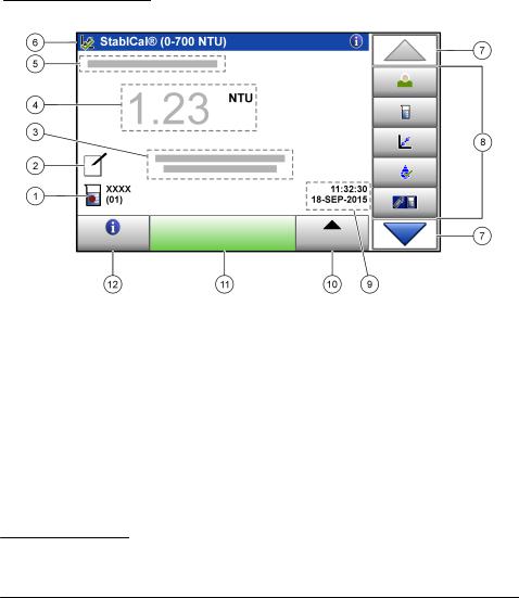
User interface and navigation
The instrument display is a touch screen. Only use a clean, dry finger tip to navigate the functions of the touch screen. Do not use writing tips of pens or pencils or other sharp objects to make selections on the screen or damage to the screen will occur.
Refer to Figure 3 for an overview of the home screen.
Figure 3 Display overview
1 |
Sample ID and measurement number4 |
7 |
UP/DOWN navigation arrows |
2 |
User comments |
8 |
Sidebar menu (refer to Table 2) |
|
|
|
|
3 |
Instructions |
9 |
Time and date |
|
|
|
|
4 |
Turbidity value, unit and reading mode |
10 |
Options button |
|
|
|
|
5 |
Warning or error message |
11 |
Read button |
|
|
|
|
6 |
Calibration status icon and calibration curve |
12 |
Information (help) button |
|
|
|
|
3As an alternative to the touchscreen, use a keyboard to enter text into text boxes on the display
(e.g., passwords and sample IDs).
4 The measurement number increases by one each time a measurement is completed.
10 English
Loading...