


 Loading...
DOC022.53.00720
DR 2800
USER MANUAL
January 2008, Edition 2
© HACH Company, 2007–2008. All rights reserved. Printed in Germany.

2

|
|
Table of Contents |
Section 1 Specifications ........................................................................................................................................ |
7 |
|
Section 2 General Information .............................................................................................................................. |
9 |
|
2.1 |
Safety information .............................................................................................................................................. |
9 |
|
2.1.1 Use of hazard information ......................................................................................................................... |
9 |
|
2.1.2 Precautionary labels ................................................................................................................................. |
9 |
|
2.1.3 Class 1 LASER ......................................................................................................................................... |
9 |
|
2.1.4 Chemical and Biological Safety .............................................................................................................. |
10 |
2.2 |
Overview of product ......................................................................................................................................... |
10 |
Section 3 Installation ........................................................................................................................................... |
11 |
|
3.1 |
Unpack the instrument ..................................................................................................................................... |
11 |
3.2 |
Operating environment .................................................................................................................................... |
11 |
3.3 |
Power connections ........................................................................................................................................... |
12 |
3.4 |
Connection ....................................................................................................................................................... |
13 |
3.5 |
Cell compartments, Cell adapters, Light Shield and Protective Cover ............................................................. |
14 |
|
3.5.1 Cell compartments and adapters ............................................................................................................ |
14 |
|
3.5.2 Installation of the cuvette/sample cell adapters ...................................................................................... |
15 |
|
3.5.3 Use of the light shield for measurements ................................................................................................ |
16 |
|
3.5.4 Protective Cover ..................................................................................................................................... |
18 |
3.6 |
Mobile use of the DR 2800 for field analysis .................................................................................................... |
19 |
|
3.6.1 Position the Protective Cover .................................................................................................................. |
20 |
3.7 |
Beam path ........................................................................................................................................................ |
21 |
Section 4 Start Up ................................................................................................................................................ |
23 |
|
4.1 |
Power the instrument on and off ...................................................................................................................... |
23 |
4.2 |
Language selection .......................................................................................................................................... |
23 |
4.3 |
Self-Check ....................................................................................................................................................... |
23 |
Section 5 Standard Operations ........................................................................................................................... |
25 |
|
5.1 |
Overview .......................................................................................................................................................... |
25 |
|
5.1.1 Tips for the use of the touch screen ........................................................................................................ |
25 |
|
5.1.2 Use of the alphanumeric keypad ............................................................................................................ |
25 |
|
5.1.3 Main Menu .............................................................................................................................................. |
26 |
5.2 |
Instrument Setup mode .................................................................................................................................... |
27 |
|
5.2.1 Operator ID ............................................................................................................................................. |
27 |
|
5.2.2 Sample ID ............................................................................................................................................... |
28 |
|
5.2.3 Date and time .......................................................................................................................................... |
29 |
|
5.2.4 Display and sound preferences .............................................................................................................. |
29 |
|
5.2.5 Power Management ................................................................................................................................ |
29 |
|
5.2.6 PC and printer ......................................................................................................................................... |
31 |
|
5.2.6.1 Printer setup ............................................................................................................................... |
31 |
|
5.2.6.2 Print data .................................................................................................................................... |
33 |
|
5.2.6.3 HACH Data Trans ....................................................................................................................... |
33 |
|
5.2.7 Password ................................................................................................................................................ |
34 |
|
5.2.7.1 Password deactivation ................................................................................................................ |
35 |
3

Table of Contents |
|
5.3 Store, recall, send and delete data .................................................................................................................. |
37 |
5.3.1 The data log ............................................................................................................................................ |
37 |
5.3.1.1 Auto/manual data storage ........................................................................................................... |
37 |
5.3.1.2 Recall stored data from the data log ........................................................................................... |
37 |
5.3.1.3 Send data from the data log ....................................................................................................... |
38 |
5.3.1.4 Delete stored data from the data log .......................................................................................... |
39 |
5.3.2 Time Course ........................................................................................................................................... |
40 |
5.3.2.1 Data Storage from Time Course ................................................................................................. |
40 |
5.3.2.2 Recall Stored Data from Time Course ........................................................................................ |
40 |
5.3.2.3 Send Data from Time Course ..................................................................................................... |
41 |
5.3.2.4 Delete Stored Data from Time Course ....................................................................................... |
42 |
5.4 Stored Programs .............................................................................................................................................. |
43 |
5.4.1 Select a saved test/method; enter user-specific basic data .................................................................... |
43 |
5.4.2 Stored program options .......................................................................................................................... |
43 |
5.4.3 Use of program timers ............................................................................................................................ |
45 |
5.4.4 Set the dilution factor .............................................................................................................................. |
46 |
5.4.5 Run a standard adjust ............................................................................................................................. |
46 |
5.4.6 Set the chemical form ............................................................................................................................. |
47 |
5.4.6.1 Change of the default setting of the chemical form .................................................................... |
48 |
5.4.7 Run a reagent blank ................................................................................................................................ |
48 |
5.4.8 Analysis of samples ................................................................................................................................ |
49 |
5.4.9 Add stored programs to the favorite programs list .................................................................................. |
50 |
5.5 Barcode Programs ........................................................................................................................................... |
51 |
5.5.1 Complete a barcode 13 mm test/vial ...................................................................................................... |
51 |
5.5.2 Select the measuring range .................................................................................................................... |
52 |
5.5.3 Select the chemical evaluation form ....................................................................................................... |
52 |
5.5.3.1 Change of the default setting of the chemical form .................................................................... |
53 |
5.5.4 Basic test-specific and sample-specific data settings ............................................................................. |
53 |
5.5.5 Sample blank .......................................................................................................................................... |
54 |
5.5.6 Update/edit barcode tests ....................................................................................................................... |
55 |
5.5.6.1 Manual update of a barcode test ................................................................................................ |
55 |
5.5.6.2 Update an existing barcode test ................................................................................................. |
58 |
5.5.6.3 Program a new test ..................................................................................................................... |
59 |
5.5.7 Upgrade of the instrument software ........................................................................................................ |
59 |
Section 6 Advanced Operations ......................................................................................................................... |
61 |
6.1 User Programs ................................................................................................................................................. |
61 |
6.1.1 Program a user method .......................................................................................................................... |
61 |
6.1.1.1 Single wavelength settings ......................................................................................................... |
63 |
6.1.1.2 Multi wavelength settings ............................................................................................................ |
64 |
6.1.1.3 Calibration settings for single and multi wavelength mode ......................................................... |
66 |
6.1.1.4 Store a user program .................................................................................................................. |
70 |
6.1.1.5 Additional user-defined parameters and functions ..................................................................... |
70 |
6.1.2 Free programming program type ............................................................................................................ |
72 |
6.1.2.1 Measurement process ................................................................................................................ |
72 |
6.1.2.2 Enter a new element of a measuring sequence ......................................................................... |
73 |
6.1.2.3 Enter the calibration formula (evaluation formula) ...................................................................... |
75 |
6.1.2.4 Enter variables ............................................................................................................................ |
78 |
6.1.2.5 Save a free programming user program ..................................................................................... |
78 |
6.1.3 Select a user program ............................................................................................................................. |
79 |
6.1.4 Add, edit and delete user programs from the favorites list ...................................................................... |
79 |
6.1.4.1 Add to Favorites .......................................................................................................................... |
80 |
6.1.4.2 Edit .............................................................................................................................................. |
80 |
6.1.4.3 Delete ......................................................................................................................................... |
80 |
4

|
Table of Contents |
6.2 Favorite Programs ........................................................................................................................................... |
81 |
6.2.1 Recall a favorite program ........................................................................................................................ |
81 |
6.2.2 Delete a favorite program ....................................................................................................................... |
81 |
6.3 Standard Addition – monitoring/checking results ............................................................................................. |
82 |
6.3.1 Complete a standard addition ................................................................................................................. |
83 |
6.4 Single Wavelength (absorbance, concentration and transmittance measurements) ....................................... |
87 |
6.4.1 Set up single wavelength mode .............................................................................................................. |
87 |
6.4.2 Take single wavelength measurements .................................................................................................. |
89 |
6.5 Multi-Wavelength mode – measurements at more than one wavelength ........................................................ |
90 |
6.5.1 Set the reading mode at different wavelengths ....................................................................................... |
90 |
6.5.2 Complete a measurement in the multi wavelength mode ....................................................................... |
93 |
6.6 Time course of absorbance/transmittance ....................................................................................................... |
94 |
6.6.1 Time course setup parameters ............................................................................................................... |
94 |
6.6.2 Time course scan reading ....................................................................................................................... |
95 |
6.6.3 Analysis of time course data ................................................................................................................... |
96 |
6.6.3.1 Navigation of a time scan or a time scan analysis ...................................................................... |
97 |
6.7 System checks ................................................................................................................................................. |
97 |
6.7.1 Instrument information ............................................................................................................................ |
98 |
6.7.2 Upgrade of the instrument software ........................................................................................................ |
98 |
6.7.3 Optical checks ......................................................................................................................................... |
99 |
6.7.3.1 Wavelength check ...................................................................................................................... |
99 |
6.7.3.2 Stray light check ....................................................................................................................... |
100 |
6.7.3.3 Absorbance check .................................................................................................................... |
101 |
6.7.3.4 Verification kit ........................................................................................................................... |
102 |
6.7.4 Output checks ....................................................................................................................................... |
104 |
6.7.5 Lamp history ......................................................................................................................................... |
104 |
6.7.6 Factory service ...................................................................................................................................... |
104 |
6.7.7 Service time .......................................................................................................................................... |
105 |
6.7.8 Instrument Backup ................................................................................................................................ |
106 |
Section 7 Maintenance ...................................................................................................................................... |
109 |
7.1 Cleaning requirements ................................................................................................................................... |
109 |
7.1.1 Spectrophotometer ............................................................................................................................... |
109 |
7.1.2 Display .................................................................................................................................................. |
109 |
7.1.3 Cuvettes/sample cells ........................................................................................................................... |
109 |
7.2 Insert or change of the battery ....................................................................................................................... |
110 |
7.2.1 Information about using the battery ...................................................................................................... |
111 |
7.2.1.1 Dispose of the lithium battery ................................................................................................... |
111 |
7.2.1.2 Optimal operation of the battery ............................................................................................... |
112 |
7.2.1.3 Lifespan of the battery .............................................................................................................. |
112 |
7.2.1.4 Load the battery/Operating time ............................................................................................... |
112 |
7.3 Lamp replacement ......................................................................................................................................... |
113 |
Section 8 Troubleshooting ................................................................................................................................ |
117 |
Section 9 Replacement Parts ............................................................................................................................ |
119 |
Section 10 Contact Information ........................................................................................................................ |
121 |
Section 11 Limited Warranty ............................................................................................................................. |
123 |
Index .................................................................................................................................................................... |
125 |
5

Table of Contents
6

Section 1 |
Specifications |
|
|
|
Specifications are subject to change without notice. |
|
|
|
Performance Specifications |
|
|
|
|
|
Operating Mode |
|
Transmittance (%), Absorbance and Concentration |
|
|
|
Source Lamp |
|
Gas-filled Tungsten (visible) |
|
|
|
Wavelength Range |
|
340–900 nm |
|
|
|
Wavelength Accuracy |
|
± 1.5 nm |
|
|
|
Wavelength Reproducibility |
< 0.1 nm |
|
|
|
|
Wavelength Resolution |
|
1 nm |
|
|
|
Wavelength Calibration |
|
Automatic |
|
|
|
Wavelength Selection |
|
Automatic, based on method selection |
|
|
|
Spectral Bandwidth |
|
< 8 nm |
|
|
|
Photometric measuring range |
± 3.0 Ext in Wavelength Range 340–900 nm |
|
|
|
|
Photometric Accuracy |
|
5 mAbs at 0.0–0.5 Abs |
|
1% at 0.50–2.0 Abs |
|
|
|
|
|
|
|
|
|
< 0.5%–2 Abs |
Photometric Linearity |
|
< = 1% at > 2 Abs |
|
|
with neutral glass at 546 nm |
|
|
|
Stray Light |
|
< 0.2% T @ 340 nm with KV450/3 |
|
< 0.1% T @ 340 nm with NaNO2 |
|
|
|
|
Data storage |
|
500 measured values (result, date, time, sample ID, user ID) |
|
|
|
User programs |
|
50 |
|
|
|
Physical and Environmental Specifications |
||
|
|
|
Width |
|
220 mm (8.6 in) |
|
|
|
Height |
|
135 mm (5.3 in) |
|
|
|
Depth |
|
330 mm (12.9 in) |
|
|
|
Weight |
|
4.06 kg (8.95 Ibs) without battery |
|
4.38 kg (9.66 Ibs) with battery |
|
|
|
|
|
|
|
Operating Requirements |
10–40 °C (50–104 °F), max. 80% relative humidity (non-condensing) |
|
|
|
|
Storage Requirements |
|
-40–60 °C (-40–140 °F) max. 80% relative humidity (non-condensing) |
|
|
|
Additional technical data |
|
|
|
|
|
Mains connection |
|
15 V- / 30VA |
|
Plug-in power supply unit: (100–240 V/50–60 Hz) |
|
|
|
|
|
|
|
|
|
Use only shielded cable with max. length of 3 m. |
Interfaces |
|
1 x USB type A |
|
|
1 x USB type B |
|
|
|
Enclosure Rating |
|
IP 41 with closed lid |
|
IP 42 with Protective Cover in place |
|
|
|
|
|
|
|
Safety class |
|
Safety class II |
|
|
|
7

Specifications
8
Section 2 General Information
2.1 Safety information
Please read this entire manual before unpacking, setting up or operating this equipment. Pay attention to all danger, warning and caution statements. Failure to do so could result in serious injury to the operator or damage to the equipment.
Make sure that the protection provided by this equipment is not impaired, do not use or install this equipment in any manner other than that specified in this manual.
2.1.1 Use of hazard information
DANGER
Indicates a potentially or imminently hazardous situation which, if not avoided, will result in death or serious injury.
WARNING
Indicates a potentially or imminently hazardous situation which, if not avoided, could result in death or serious injury.
CAUTION
Indicates a potentially hazardous situation that may result in minor or moderate injury.
Important Note: Indicates a situation which, if not avoided, may cause damage to the instrument. Information that requires special emphasis.
Note: Information that supplements points in the main text.
2.1.2 Precautionary labels
Read all labels and tags attached to the instrument. Personal injury or damage to the instrument could occur if not observed. A symbol, if noted on the instrument, will be included with a danger or caution statement in the manual.
This symbol, if noted on the instrument, references the instruction manual for operation and/or safety information.
Electrical equipment marked with this symbol may not be disposed of in European public disposal systems after 12 August of 2005. In conformity with European local and national regulations (EU Directive 2002/96/EC), European electrical equipment users must now return old or end-of life equipment to the Producer for disposal at no charge to the user.
Note: For return for recycling, please contact the equipment producer or supplier for instructions on how to return end-of-life equipment, producer-supplied electrical accessories and all auxiliary items for proper disposal.
|
|
|
This symbol indicates that the instrument contains a Class 1 LASER device. |
|
LASER CLASS 1 |
|
|
|
|
Data: 0.3 mW; λ = 650 nm |
|
|
|
|
|
2.1.3 Class 1 LASER
A Class 1 LASER is installed in this instrument. Class 1 LASERS are products where the radiant power of the LASER beam accessible (the accessible emission) is always below the Maximum
9

General Information
Permissible Exposure value. Therefore, for Class 1 LASERS the output power is below the level at which it is believed eye damage will occur. Exposure to the beam of a Class 1 LASER will not result in eye injury. Class 1 LASERS may therefore be considered safe. However, Class 1 LASER products may contain LASER systems of a higher Class but there are adequate engineering control measures to ensure that access to the beam is not reasonably likely. Examples of such products include LASER printers and compact disc players. CDRH assession number 0510555-02.
Data: 0.3 mW; wavelength = 650 nm
2.1.4 Chemical and Biological Safety
DANGER
Potential Chemical/ Biological Exposure Hazards. Handling chemical samples, standards and reagents can be dangerous. Users of this product are advised to familiarize themselves with safety procedures and the correct use of chemicals, and to carefully read all relevant Material Safety Data Sheets.
Normal operation of this instrument may involve the use of hazardous chemicals or biologically harmful samples.
•The user must observe all cautionary information printed on the original solution containers and safety data sheet prior to their use.
•All waste solutions must be disposed in accordance with local and national law.
•The type of protective equipment must be selected according to the concentration and amount of the dangerous substance at the specific workplace.
2.2 Overview of product
The DR 2800 spectrophotometer is a VIS spectrophotometer with a wavelength range of 340 to 900 nm. The instrument comes with a complete set of application programs and multi-language support.
The DR 2800 spectrophotometer contains the following application modes: Stored Programs (pre-installed tests), Barcode Programs, User Programs, Favorite Programs, Single Wavelength Mode, Multi-Wavelength Mode and Time Course Mode.
The DR 2800 spectrophotometer provides digital readouts in direct concentration units, absorbance, or percent transmittance.
When a user-generated or programmed method is selected, the on-screen menus and prompts direct the user through the test.
This menu system also can be used to generate reports, statistical evaluations of generated calibration curves, and to report instrument diagnostic checks.
10
Section 3 |
Installation |
WARNING
Electrical and Fire Hazards. Use only the provided power supply. Only qualified personnel should conduct the tasks described in this section of the manual.
3.1 Unpack the instrument
The DR 2800 Spectrophotometer comes packaged with the following items:
•DR 2800 spectrophotometer
•Plug-in power supply, including 4 adapter for EU, GB, USA, AUS/China
•Dust cover
•3 different cuvette/cell adapters (A, B and C)
•Light Shield belongs to standard configuration of DR 2800
•Protective Cover
•DR 2800 User Manual
•CD-ROM containing the HACH and HACH LANGE procedures
•Quick start guide
Note: If any of these items are missing or damaged, contact the manufacturer or a sales representative immediatly.
3.2 Operating environment
The following conditions are necessary to ensure correct instrument operation and accurate results:
•Place the instrument firmly on an even surface. Do not push any objects under the instrument.
•Maintain an ambient temperature of 10 to 40 ºC (50 to 104 ºF) for proper instrument operation.
•The relative humidity should be less than 80%; moisture should not condense on the instrument.
•Leave at least a 15 cm (6 in.) clearance at the top and on all sides for air circulation to avoid overheating of electrical parts.
•Do not operate or store the instrument in extremely dusty, damp or wet locations.
•Keep the surface of the instrument, the cell compartment and all accessories clean and dry at all times. Splashes or spills on and in the instrument should be cleaned up immediately (see section 7.1 on page 109).
Important Note: Protect the instrument from temperature extremes, including heaters, direct sunlight and other heat sources.
11
Installation
3.3 Power connections
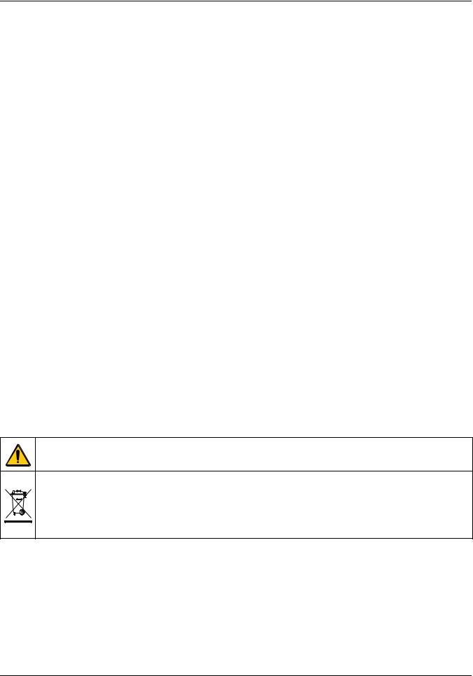
Install the correct adapter plug on the supplied external power supply (Figure 1) by sliding the adapter on until it "clicks" into position. Correctly mounted, both housing of power supply and plug are in line. Plug the external power supply cord into the connector on the back panel of the instrument, then plug the supply into a power outlet (100–240 V~ / 50–60 Hz). Press the power switch on the back of the instrument to initialize power
(Figure 2 on page 13).
|
|
Figure 1 Power adapter |
||
1 |
Power supply with EU adapter plug installed |
|
3 |
USA adapter plug |
|
|
|
|
|
2 |
UK adapter plug |
|
4 |
AUS/China adapter plug |
|
|
|
|
|
12
Installation
3.4 Connection
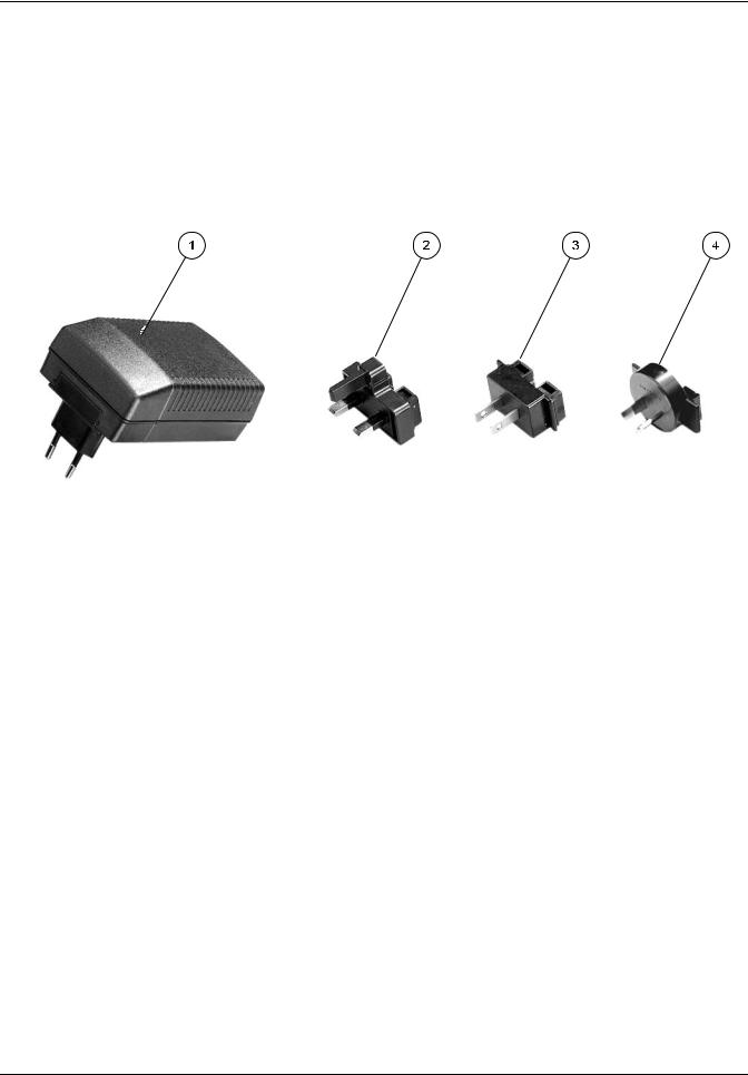
The DR 2800 has two USB interfaces as a standard feature, located on the back of the instrument (Figure 2).
The USB Type A interface is used for communications with a printer, USB memory stick, barcode scanner, or keyboard. A USB memory stick is used to update instrument software.
The USB Type B interface is used for communications with a PC. The optional Hach Data Trans software (see section 5.2.6.3 on page 33) must be installed on the PC for this use.
A USB hub may be used to connect several accessories at a time.
Note: USB cables must not be longer than 3 meters (10 feet).
These USB interfaces enable data and graphics to be output to a Printer and a PC and upgrade instrument software (see
section 6.7.2 on page 98).
|
Figure 2 |
Interfaces |
|
1 |
On/Off switch |
4 |
Cover |
|
|
|
|
2 |
USB type B |
5 |
USB type A |
|
|
|
|
3 |
Plug in power supply |
|
|
|
|
|
|
13
Installation
3.5 Cell compartments, Cell adapters, Light Shield and Protective Cover
3.5.1 Cell compartments and adapters
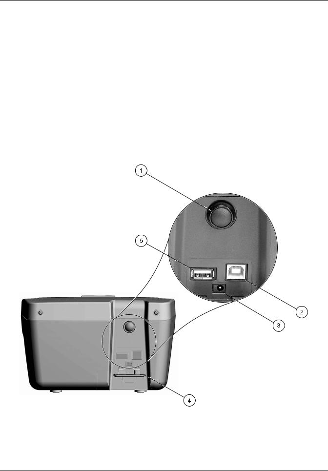
The DR 2800 has two cell compartments (Figure 3). Only one cuvette/sample cell type at a time can be used for a measurement.
Cell compartment #1
•13-mm and 16-mm round cuvettes/vials
Note: Cell compartment #1 contains a barcode reader for cuvettes/vials.
Cell compartment #2
Cell compartment #2 uses adapters to accommodate different cuvette/sample cell types.
•1-inch square or 50-mm rectangular cuvettes/cells (can be inserted directly into the cell compartment without using an adapter).
•Adapter A: 10-mm square cuvettes/cells
•Adapter B: Pour-Thru cells (refer to the instruction sheet supplied with the Pour-Thru cell) and multi-path cuvettes/cells
Note: Pour-Thru Cell must be used with Adapter B, not Adapter C.
•Adapter C: One-inch round cuvettes/cells and AccuVac® Ampules
Note: One-inch round cuvettes/cells and AccuVac Ampules must be used with Adapter C, not Adapter B.
Figure 3 |
Cell compartments |
|
1 Cell compartment #1 |
|
2 Cell compartment #2 |
|
|
|
14

Installation
|
Figure 4 |
Cuvette/Sample cell adapters |
|
1 |
10 mm square cuvette/sample cell adapter (A) |
|
3 1 inch round cuvette/sample cell adapter (C) |
|
|
|
|
2 |
1 inch Pour-Thru adapter (B) |
|
|
|
|
|
|
3.5.2Installation of the cuvette/sample cell adapters
1.Open the cell compartment.
2.Select the correct adapter for the cuvette/sample cell type.
3.Insert the adapter so the arrow on top of the adapter points to the left (Figure 5 on page 16) and the orientation tab fits the groove in the compartment opening. The cuvette/sample cell type imprint should be legible on the adapter (Figure 4).
Note: The arrow on top of the adapter indicates the direction of the light beam path.
15

Installation
Figure 5 Installation of a cuvette/sample cell adapter
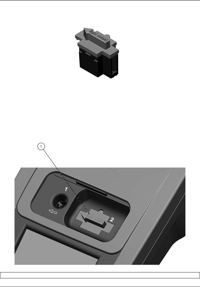
3.5.3 Use of the light shield for measurements
The light shield (Figure 6 on page 17) prevents light interference when using 13 mm and 16 mm vial tests and must be in place before measurements can be taken in cell compartment #1. The light shield is required only when using 13 mm or 16 mm vial tests.
16
Installation
The DR 2800 is shipped with the light shield installed. Remove the light shield before using cell compartment #2. The light shield can be stored in the Protective Cover (Figure 8 on page 18)
Figure 6 Light Shield
Installation of the light shield
1.Open the cell compartment.
2.Insert the light shield so the arrow on the light shield points to the left and the orientation tab fits the groove in the compartment opening (Figure 7).
Figure 7 Light Shield in place
1 Light Shield
17
Installation
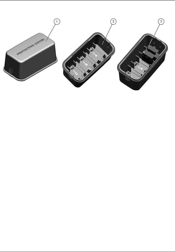
3.5.4 Protective Cover
|
Figure 8 |
Protective Cover |
|
1 |
Protective Cover |
|
3 Protective Cover with inserted cuvette/sample cell |
|
|
|
adapter A in position A. |
2 |
Protective Cover (inside view) |
|
|
|
|
||
|
The inside of the Protective Cover is intended to house |
|
|
|
the cuvette/sample cell adapters. The recesses for |
|
|
|
holding the cuvette/sample cell adapters are marked with |
|
|
|
the corresponding letters. |
|
|
|
|
|
|
18

Installation
3.6 Mobile use of the DR 2800 for field analysis
If the DR 2800 spectrophotometer is used to carry out field analyzes, it may be necessary to take a number of measures to compensate for the fluctuating ambient light conditions.
You should take the measures described below if the following warning is displayed after you take a measurement:
Error: Too much ambient light! Move device into shade or close the lid!
General measure:
Shield the instrument from the sun by standing so that your shadow falls on it, and carry out the measurement again. If the warning appears again, take the following measures.
Measures:
Measurements in a 10 mL round cuvette/cell, a rectangular cuvette/cell or AccuVac Ampules
Close the lid of the cuvette compartment and carry out the measurement.
Measurements in a 13 or 16 mm round cuvette/vial or a 25 mL square cuvette/cell
To obtain consistent measurement conditions in all weather conditions, place the Protective Cover on the open cuvette/cell compartment (see Figure 9 Position the Protective Cover on page 20) and carry out the measurement.
Important Note: When you carry out measurement in 25 mL square cuvettes/cells, take care that there is no adapter in the Protective Cover.
The enclosure rating of the photometer increases from IP41 to IP42 when the Protective Cover is in place.
19
Installation
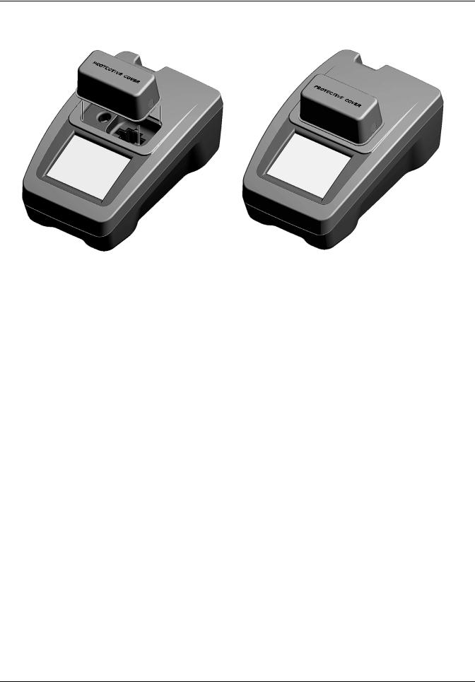
3.6.1 Position the Protective Cover
Figure 9 Position the Protective Cover
1.After you have inserted the zero solution cell or the sample cell, position the Protective Cover over the open cell compartment. The lettering "Protective Cover" must be readable from the display side of the instrument.
2.Press the Protective Cover lightly into the correct position until the cell compartment is completely sealed and the Protective Cover cannot slip off.
3.Carry out the measurement.
Note: The Protective Cover can simultaneously be used to house the different cuvette adapters. The cuvette adapter recesses in the Protective Cover are marked with the corresponding letters and arrows of the adapter. The arrows in the Protective Cover and on the adapters indicate the direction of insertion.
20
Installation
3.7 Beam path
Figure 10 shows the beam path of the DR 2800:
|
|
Figure 10 Beam path |
||
1 |
Tungsten lamp |
|
8 |
Splitter mirror |
|
|
|
|
|
2 |
Entrance slit |
|
9 |
Reference-element |
|
|
|
|
|
3 |
Heat-protection glass |
|
10 |
Cell compartment #2 |
|
|
|
|
|
4 |
Grating |
|
11 |
Lens |
|
|
|
|
|
5 |
Exit slit |
|
12 |
Measurement element |
|
|
|
|
|
6 |
Lens |
|
13 |
Cell compartment #1 |
|
|
|
|
|
7 |
Filter wheel |
|
14 |
LED |
|
|
|
|
|
21

Installation
22
Section 4 Start Up
4.1Power the instrument on and off
1.Plug in to the power supply (laboratory analysis) or insert the battery (field analysis).
2.The push-button switch on the back of the instrument switches the instrument on (press for about 1 second) and off (press for about 3 to 5 seconds). An acoustic signal confirms that the instrument has been switched off.
Note: Do not turn the instrument off and on in rapid succession. Always wait about 20 seconds before turning the instrument on again, otherwise the electronic and mechanical systems will be damaged.
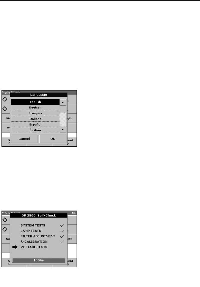
4.2 Language selection
The spectrophotometer software includes several language options. The first time the instrument is turned on, the language selection screen will appear.
1.Select the desired language.
2.Press OK to confirm the language selection. The self check will start automatically.
Change the language setting
The instrument functions in the selected language until the option is changed.
1.While turning the instrument on, touch the screen at any point until the list for selecting a language appears
(about 30 seconds).
2.Select the required language.
3.Press OK to confirm. The test program subsequently starts automatically.
4.3 Self-Check
Each time the instrument is powered up, a series of diagnostic tests are performed automatically to ensure operation of major system components.
This procedure, which takes approximately two minutes, checks the system, lamp, filter adjustment, wavelength calibration and voltage. Each test which functions correctly is confirmed with a check mark.
The Main Menu is displayed when power up diagnostics are completed.
23
Start Up
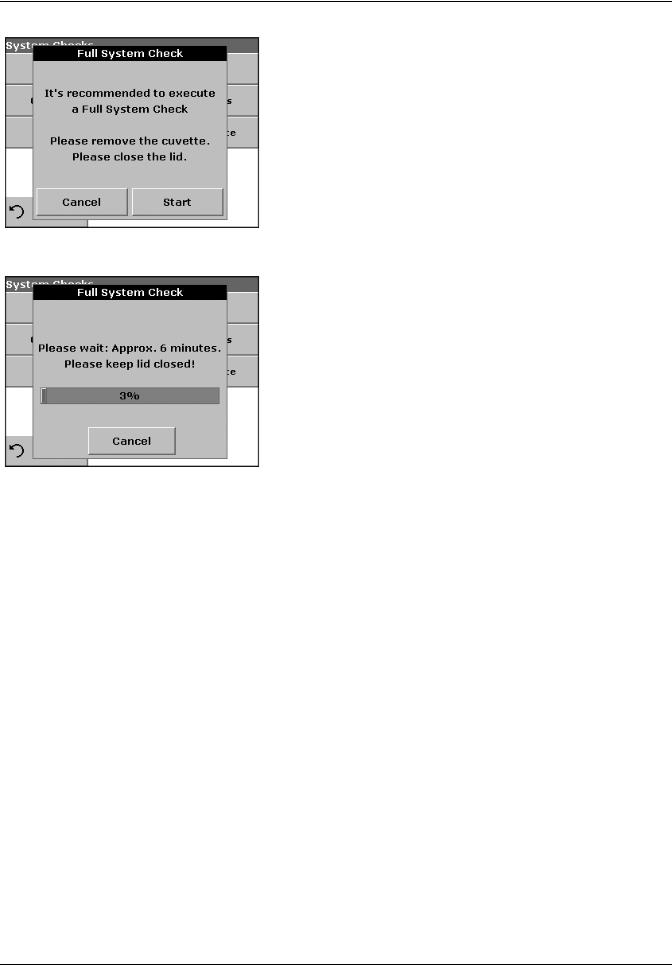
If the instrument detects any deviation relative to the last calibration, a system check has to be carried out.
4.Remove the cuvette from the cell compartment and close the lid.
5.Then press Start.
The system check is carried out (duration approx. 6 minutes).
Note: Further error messages during self check, see Section 8 on page 117.
24
Section 5 Standard Operations
5.1 Overview
5.1.1 Tips for the use of the touch screen
The entire screen is touch-activated. To make a selection, press the screen with a fingernail, fingertip, pencil eraser or a stylus. Do not press the screen with a sharp object, such as the tip of a ball point pen.
•Do not place anything on top of the screen, to prevent damage or scratching on the screen.
•Press keys, words or icons to select them.
•Use scroll bars to move up and down long lists very quickly. Press and hold the scroll bar, then move up or down to move through the list.
•Highlight an item from a list by pressing it once. When the item has been successfully selected, it will be displayed as reversed text (light text on a dark background).
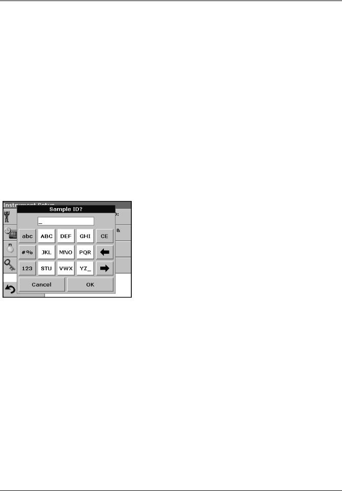
5.1.2Use of the alphanumeric keypad
|
|
This display is used to enter letters, numbers and symbols as |
|
|
|
needed when programming the instrument. Unavailable options are |
|
|
|
disabled (grayed out). The icons on the right and left of the screen |
|
|
|
are described in Table 1. |
|
|
|
The central keypad changes to reflect the chosen entry mode. |
|
|
|
Press a key repeatedly until the desired character appears on the |
|
|
|
screen. A space can be entered by using the underscore on the |
|
|
|
YZ_ key. |
|
|
|
Note: A USB keyboard (with US keyboard layout) or a USB Barcode |
|
|
|
handset scanner can be used for input (see Section 9 on page 119). |
|
|
|
Table 1 Alphanumeric keypad |
|
|
|
|
|
Icon / key |
Description |
Function |
|
|
|
|
|
ABC/abc |
Alphabetic |
When entering alphabetic characters (ex. user-entered units), this key allows to |
|
toggle between upper and lower case letters. |
|||
|
|
||
|
|
|
|
# % |
Symbols |
Punctuation, symbols and numerical suband superscripts may be entered. |
|
|
|
|
|
123 |
Numeric |
For entering regular numbers. |
|
|
|
|
|
CE |
Clear Entry |
Clear the entry. |
|
|
|
|
|
Left Arrow |
Backspace |
Moves back one position. This deletes the character previously entered in the new |
|
position. |
|||
|
|
||
|
|
|
|
Right Arrow |
Advance |
Moves to the next space in an entry when two adjacent characters occur on the |
|
same key. |
|||
|
|
25

Standard Operations
5.1.3 Main Menu
A variety of modes may be selected from the ”Main Menu“. The following table briefly describes each menu option.
|
Table 2 ”Main Menu“ Options DR 2800 |
|
|
|
|
Option |
Function |
|
|
|
|
Stored Programs / |
Stored programs are pre-programmed methods that make use of HACH reagents and LANGE |
|
Barcode Programs |
cuvette tests and pipette tests. |
|
(HACH LANGE |
The DR 2800 Procedures Manual contains illustrated, step-by-step procedures for analyzes |
|
Programs) |
using HACH programs. The working procedures for LANGE tests are included in the test packs. |
|
|
|
|
|
User programs make "made to measure analysis" possible: |
|
User Programs |
- Users can program methods they have developed themselves |
|
- Existing HACH and LANGE methods can be stored as user programs. The LANGE tests can |
||
|
||
|
then be modified to suit the user's requirements. |
|
|
|
|
Favorite Programs |
List of methods/tests created by the user to suit his own requirements. |
|
|
|
|
|
Single wavelength measurements are: |
|
|
Absorbance measurements: The light absorbed by the sample is measured in absorbance |
|
|
units. |
|
Single Wavelength |
Transmittance measurements (%): The percentage of the light that passes through the sample |
|
|
and reaches the detector is measured. |
|
|
Concentration measurements: A concentration factor can be entered to enable the measured |
|
|
absorbance values to be converted into concentration values. |
|
|
|
|
|
In the multi-wavelength mode, absorbance (Abs) or percentage transmittance (%T) is measured |
|
Multi Wavelength |
at up to four wavelengths, and absorbance differences and absorbance relationships are |
|
|
calculated. Simple conversions into concentrations can also be carried out. |
|
Time Course |
The time scan records the absorbance or % transmittance at a wavelength over a defined time. |
|
|
|
|
System Checks |
The system checks menu offers a number of options, including optical checks, output checks, |
|
lamp history, instrument update, service time and instrument backup. |
||
|
||
|
|
|
Recall Data |
Stored data can be called up, filtered, transmitted and deleted. |
|
|
|
|
Instrument Setup |
In this mode, user-specific or method-specific settings can be entered: Operator-ID, Sample-ID, |
|
Date & Time, Display & Sound, Power Management, PC & Printer and Password. |
||
|
||
|
|
26
Standard Operations
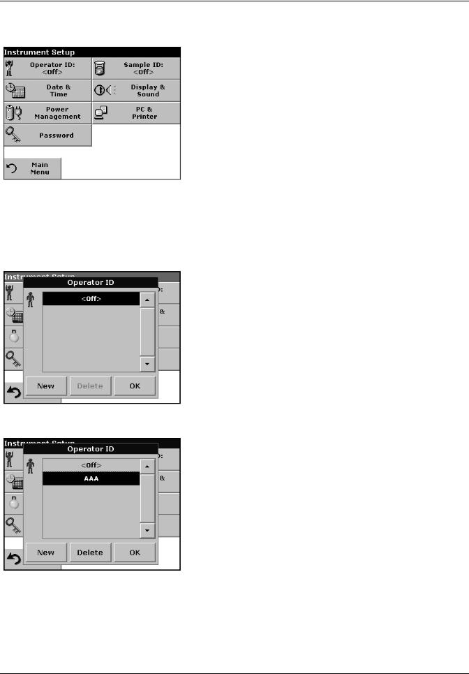
5.2 Instrument Setup mode
1. Select Instrument Setup in the ”Main Menu“.
A selection of functions appears in order to configure the functions of the instrument.
5.2.1 Operator ID
Use this option to enter up to 30 sets of operator initials (up to
5 characters each) into the instrument. This feature helps record which operator measured each sample.
1.Press Operator ID in the Instrument Setup.
2.Press New to enter a new Operator ID.
3.Use the alphanumeric keypad to enter a new Operator ID.
4.Press OK to confirm.
5.The display shows the chosen Operator ID.
6.Press OK. The instrument will return to the Instrument Setup screen and show the selected operator identifier.
7.The chosen Operator ID is activated.
Note: Press Delete to remove an Operator ID from the list.
Note: Alternatively, enter or change an Operator ID in measurement mode. In the results screen, press Options>More>Instrument Setup or if an Operator ID is already assigned, select the "Operator ID symbol immediately in the results screen.
27
Standard Operations
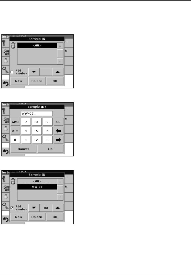
5.2.2 Sample ID
Use this option to enter up to 100 Sample Identification tags (up to 13 characters each) into the instrument. Sample IDs can be used to specify the sample location or other sample specific information.
1.Press Sample ID in the Instrument Setup.
2.Press New to enter a new Sample ID.
3.Use the alphanumeric keypad to enter a new Sample ID.
Note: If a USB Barcode handset scanner ( see Section 9 on page 119) is connected, Sample IDs can also be scanned. Sample IDs can also be entered with a USB keyboard.
4.Press OK to confirm.
5.To number the Sample IDs sequentially (e.g. Inflow (01 etc.)), select Add Number.
•Use the arrow keys to specify the first number of the sequence.
•Use the key between the arrow keys to enter the first number of the sequence using the alphanumeric keypad.
6.Press OK to return to "Instrument Setup".
7.The Sample ID is activated. Each Sample ID is automatically numbered in ascending order after a measurement. The number is shown in parentheses behind the Sample ID.
Note: To remove a Sample ID, highlight the ID and press Delete.
Note: A Sample ID can be entered or changed in measurement mode. In the results screen, press Options>More>Instrument Setup. If a Sample ID is already assigned, select the Sample ID symbol in the results screen.
28
Standard Operations
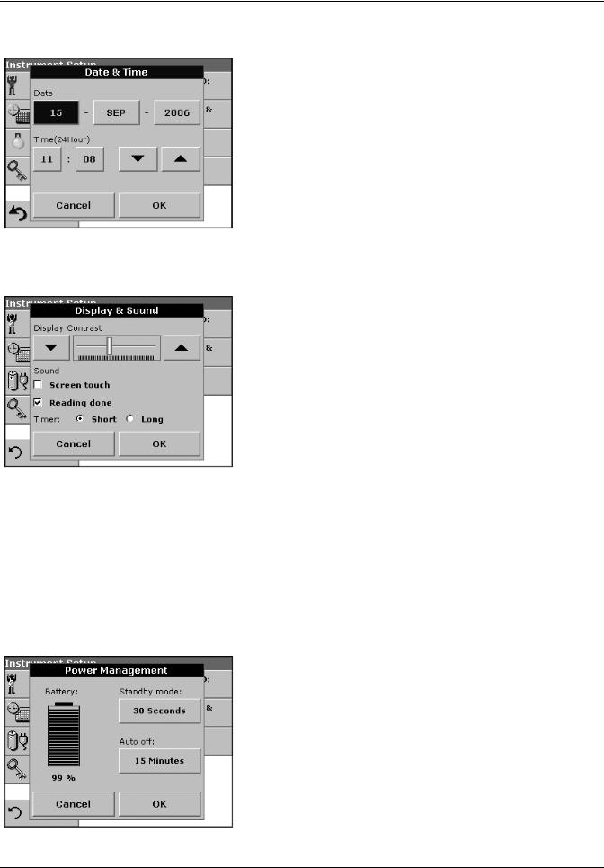
5.2.3 Date and time
1.Press Date & Time in the Instrument Setup.
2.The date and time are subdivided over a number of fields. Press the appropriate field and use the arrow keys to change the value.
3.Press OK to confirm. The instrument will return to Instrument Setup.
5.2.4Display and sound preferences
1.Press Display & Sound in the Instrument Setup.
The following options will be displayed:
•Display Contrast—Adjusts the display brightness to suit lighting conditions.
•Screen touch—Activates//Deactivates a short beep each time the screen is pressed (Default:off).
•Reading done—Activates/Deactivates a sound when a reading is complete (Default: short beep every time a reading is complete).
•Timer—Adjusts the length of the timer sound. Select Short or Long. Long beeps are recommended for noisy environments.
2.Press OK to confirm. The instrument will return to Instrument Setup.
5.2.5 Power Management
The DR 2800 can run on mains or battery power.
Note: The battery is not part of the standard scope of delivery.
1.Select Power Management in the ”Instrument Setup“ menu.
The battery symbol indicates the charge status of the battery in %.
Note: The timer settings in the Power Management menu are only active when the instrument is running on battery power.
29
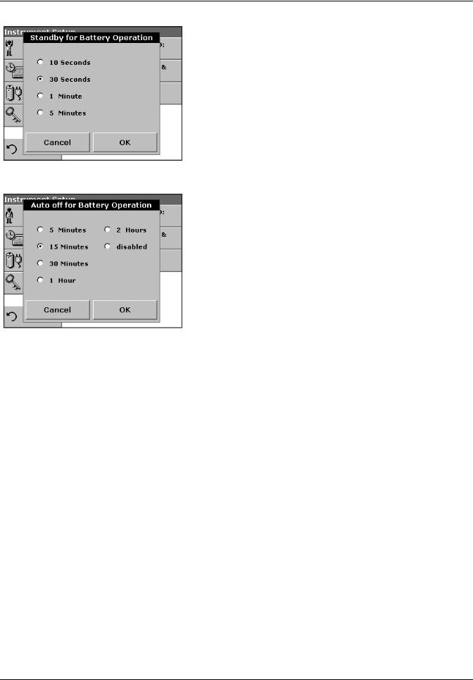
Standard Operations
2.Select one of the options under Standby mode to set the length of the idle period that can elapse before the instrument switches to the Standby mode when running on battery power.
Note: In standby mode, the backlighting of the screen is switched off. Touching the display causes the lighting to switch on again.
3.Select one of the options under Auto off to set the length of the idle period that can elapse before the instrument automatically switches off when running on battery power.
Note: After the instrument switches itself off automatically, you have to press the push-button switch on the back of the instrument to start it again.
30
Loading...