


51350

Catalog Number 51350-18
AquaTrend®Interface
Model 51200 – AquaTrend
Model 51350 – AquaTrend/SOM
Model51400–PortableAquaTrend
Instrument Manual
© Hach Company, 2001, 2002. All rights reserved. Printed in the U.S.A.
11/02 6ed

Table of Contents
Safety Precautions.................................................................................................................................................... 5
Specifications............................................................................................................................................................ 6
Operation ............................................................................................................................................................... 7
Section 1 General Description.......................................................................................................................... 9
1.1 Introduction ......................................................................................................................................................... 9
1.2 Using This Manual .............................................................................................................................................. 9
1.3 Unpacking the AquaTrend Interface................................. ....... ...... ...... ....... ...... ................................................. 10
1.3.1 Optional Equipment................................................................................................................................. 11
1.4 Instrument Description...................................................................................................................................... 11
1.4.1 Operating Environment............................................................................................................................ 11
1.4.2 AquaTrend Interface Keypad Description ................................................................................................ 12
1.4.3 AquaTrend Interface Display Description................................................................................................. 13
1.5 AquaTrend Interface Menu Organization .......................................................................................................... 16
1.5.1 Alarm Log ................................................................................................................................................ 16
1.5.2 AquaTrend Interface Menu ...................................................................................................................... 16
1.5.3 Sensor Menu ........................................................................................................................................... 16
1.5.4 Other Device Menu.................................................................................................................................. 16
1.5.5 Network Menu ......................................................................................................................................... 16
Section 2 Aquatrend® Interface Network..................................................................................................... 17
2.1 Network Description.......................................................................................................................................... 17
2.2 Device Descriptions .......................................................................................................................................... 18
2.2.1 AquaTrend Interface Module.................................................................................................................... 18
2.2.2 AquaTrend/SOM with Integrated Signal Output Module.......................................................................... 18
2.2.3 Portable AquaTrend Interface Module ..................................................................................................... 19
2.2.4 Sensor ..................................................................................................................................................... 19
2.2.5 Signal Output Module (SOM) .................................................................................................................. 19
2.2.6 Signal Input Module................................................................................................................................. 19
2.2.7 Serial I/O Module (SIO)........................................................................................................................... 19
2.2.8 Digital Display Module (DDM).................................................................................................................. 20
2.2.9 Repeater Module..................................................................................................................................... 20
2.3 Network Design................................................................................................................................................. 20
Section 3 Initial AquaTrend Setup ................................................................................................................. 23
3.1 Identifying the Master AquaTrend ..................................................................................................................... 23
3.1.1 Adding Remote AquaTrend Interfaces to the Network................................... .......................................... 23
3.2 Language Setting.............................................................................................................................................. 24
3.3 Time/Date Setting ............................................................................................................................................. 24
3.3.1 Setting the Time ........................................................................ .............................................................. 24
3.3.2 Setting the Date...................... ...... ....... ...... ....... ............................................. .......................................... 25
3.3.3 Changing the Date Format...................................................................................................................... 25
3.3.4 Setting the Correct Day of the Week....................................................................................................... 25
3.4 Network Setup .................................................................................................................................................. 26
3.4.1 Single Sensor System............................................................................................................................. 26
3.4.2 Adding a Device to the Network .............................................................................................................. 26
3.4.3 Removing or Replacing a Device ............................................................................................................ 28
3.4.3.1 Removing a Device from the Network ........................................................................................ 28
3.4.3.2 Replacing a Device on the Network............................................................................................ 29
3.4.4 Attaching a Measurement to a Channel .................................................................................................. 30
3.4.5 Detaching a Measurement from a Channel............................................................................................. 30
Page 2
Table of Contents
51350-18TOC.fm

Table of Contents
3.5 Additional AquaTrend Interface Menu Features................................................................................................ 31
3.5.1 Display Setup........................................................................................................................................... 31
3.5.1.1 Contrast Adjustment .................................. ....... ............................................. ............................. 31
3.5.1.2 Flash Backlight on Alarm........ ...... ....... ...... ....... ...... .................................................................... 32
3.5.2 Channel Graph Time Settings ................................................................................................................. 32
3.5.2.1 Setting the Graph Time (x-axis).................................................................................................. 32
3.5.2.2 Scaling the Graph Y-axis............................................................................................................ 32
3.6 Display Setup.................................................................................................................................................... 33
3.7 Edit Name ......................................................................................................................................................... 33
3.8 Security Setup................................................................................................................................................... 34
3.8.1 Setting the Password.............................................................................. ................................................. 34
3.8.2 Setting the Security Level............. ............................................. .............................................................. 35
3.8.2.1 Temporary Unlock ..... ...... ....... ...... ....... ...... ....... ...... ...... .............................................. . ............... 36
3.9 Additional Network Menu Features............................ ...... ................................................................................. 36
3.9.1 Review Net Connections ......................................................................................................................... 36
3.9.1.1 List Network Devices ..................................................................................................................37
3.9.1.2 Displaying Alarm to Relay Connection Information..................................................................... 37
3.9.1.3 Displaying Recorder to Analog Out Informat ion ......................................................................... 38
3.9.1.4 Sensor to Display........................................................................................................................ 38
3.9.1.5 Print Network Image .................................. ....... ...... ...... ....... ...... ....... ...... .................................... 39
3.10 Print Data Log ................................................................................................................................................. 39
3.11 External Network Manager ............................................................................................................................. 40
3.12 Restore Net Connections................................................................................................................................ 41
Section 4 Alarms, Relays, and Recorders ................................................................................................... 43
4.1 Alarm to Relay Connections.............................................................................................................................. 43
4.1.1 Setting Alarm Parameters ....................................................................................................................... 43
4.1.2 Attaching an Alarm to a Relay................................................................................................................. 43
4.1.3 Detaching an Alarm from a Relay............................................................................................................ 44
4.1.4 Connecting a Recorder Signal to an Output Device................................................................................ 45
4.1.5 Detaching Recorder from Analog Output ................................................................................................ 46
4.2 Alarm Log.......................................................................................................................................................... 47
Installation and Maintenance.......................................................................................................................... 49
Section 5 Hardware Installation...................................................................................................................... 51
5.1 Mounting Instructions for the AquaTrend
5.1.1 AquaTrend Interface Pole Mounting......................................................................................................... 53
5.1.2 AquaTrend Interface Wall Mounting......................................................................................................... 53
5.1.3 AquaTrend Interface Panel Mount ........................................................................................................... 55
5.2 Portable AquaTrend Interface Installation and Mounting................................................................................... 57
5.3 AquaTrend Interface Power and Network Connections..................................................................................... 60
5.3.1 AquaTrend Interface with Signal Output Module (SOM) to PS1201 Power Supply Connections ............ 60
5.3.2 SOM Recorder Output and Relay Connections....................................................................................... 64
5.3.3 AquaTrend Interface without SOM to PS1201 Power Supply Connection............................................... 64
5.4 Network Termination ......................................................................................................................................... 66
5.4.1 Network Termination at the AquaTrend with SOM or at the SOM ........................................................... 66
5.4.2 Network Termination at the AquaTrend Interface without SOM............................................................... 68
5.5 Interconnecting other Devices on the Network ................................................................................................. 69
®
Interface ......................................................................................... 51
Page 3
51350-18TOC.fm Table of Contents

Table of Contents
Section 6 Maintenance and Troubleshooting ............................................................................................. 71
6.1 Maintenance ..................................................................................................................................................... 71
6.1.1 Cleaning the AquaTrend Interface........................................................................................................... 71
6.2 AquaTrend Interface Diagnostics ...................................................................................................................... 71
6.2.1 Display Test ............................................................................................................................................. 71
6.2.2 Keyboard Test.......................................................................................................................................... 71
6.2.3 Memory Test............................................................................................................................................ 71
6.2.4 Verify Program Checksum....................................................................................................................... 72
6.2.5 Clear Alarm Log....................................................................................................................................... 72
6.2.6 AquaTrend Interface Cold Start............................................................................................................... 72
6.2.7 Service Menu........................................................................................................................................... 73
6.3 Network Diagnostics ......................................................................................................................................... 73
6.3.1 Print Network Image................................................................................................................................ 73
6.3.2 Query Device Status................................................................................................................................ 73
6.3.3 Test for Duplicate or Wrong Node............................................................................................................ 73
6.4 Troubleshooting................................................................................................................................................. 74
Glossary............................................................................................................................................................... 81
General Information........................................................................................................................................... 85
Replacement Parts and Accessories...................................................................................................................... 86
How to Order.......... ...... ............................................. ....... ............................................. .......................................... 87
Repair Service ........................................................................................................................................................ 88
Warranty ................................................................................................................................................................. 89
Certification............................................................................................................................................................. 90
Page 4
Table of Contents
51350-18TOC.fm
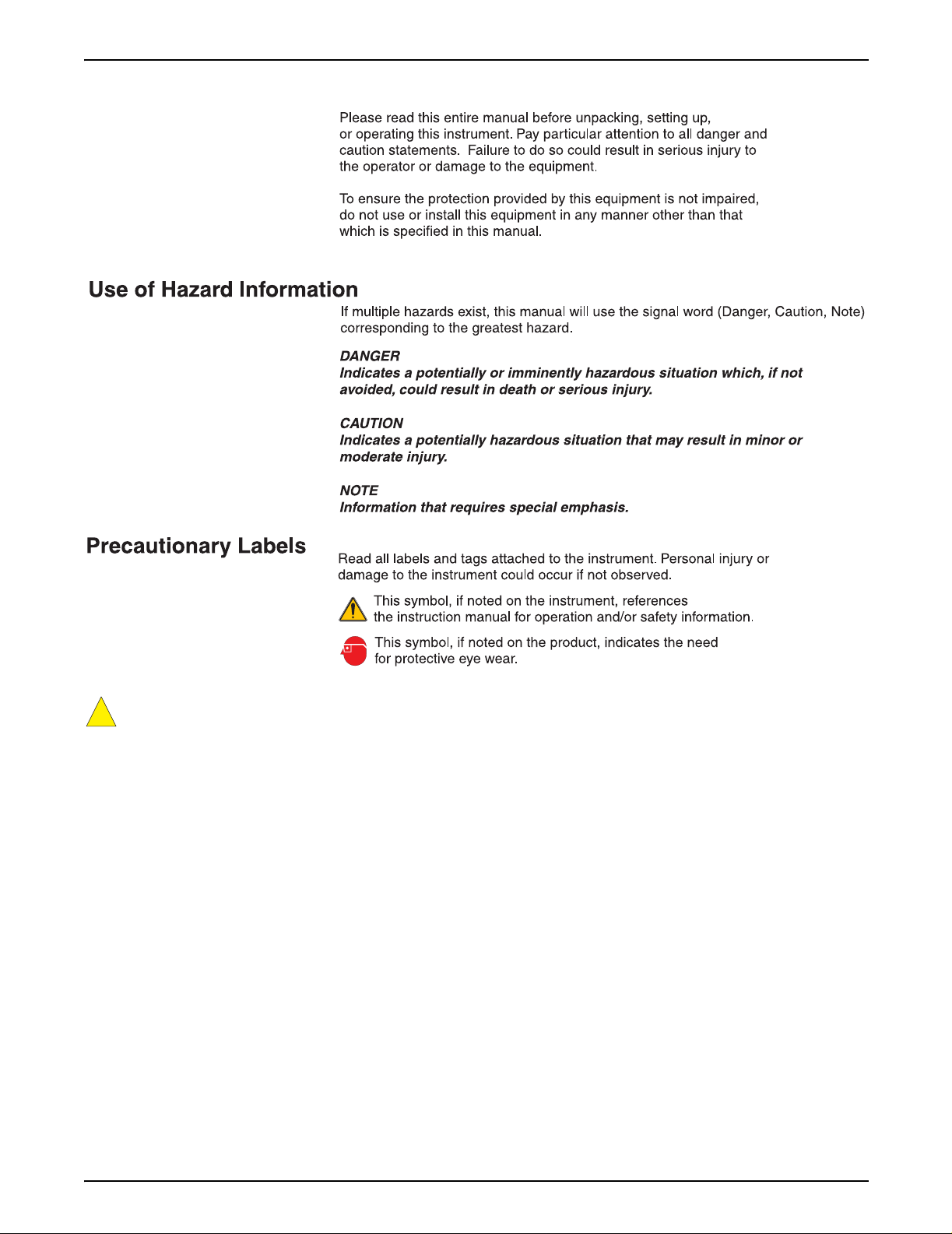
Safety Precautions
!
Section 5.3.1, AquaTrend Interface with Signal Output Module (SOM) to PS1201 Power
Supply Connections, on page 60.
Page 5
51350-18 safety page.fm Safety Precautions

Specifications
Specifications are subject to change without notice.
Sensor input capability Eight
Operating humidity 5 to 95% non-condensing
Operating temperature 0 to 40 °C (32 to 104 °F)
Storage temperature -20 to 60 °C (-4 to 140 °F)
Power requirements Exter nal power supply 12 VDC nominal ±25%
(9 to 15 VDC range) with peak to peak ripple to be less than 10% of nominal.
Enclosure NEMA 4X (indoor), IP 66
Display visibility LCD backlit, visible at 10 feet with single reading; visible at 3 feet with multiple
readings.
Clock Real time
Mounting Wall, panel, or pole
®
Shipping weight AquaTrend
4 lb Portable AquaTrend Interface: 3 lb
Outputs (AquaTrend with SOM only) Two current analog outputs; range either 4-20 mA or 0-20 mA (user selectable);
both outputs isolated to 500 VDC; may be trimmed ±20% if needed (via AquaTrend
Interface).
Relays (AquaTrend with SOM only) SPDT 250 VAC, 5A resistive
Communications Echelon
between devices with a 500 meter maximum per segment; distances in excess of
500 meters require a repeater. Up to 3 repeaters can be used for a total network
length of 2000 meters.
Data logging capability 1 hour log (1 min. intervals), 30 day log (15 min. intervals)
AquaTrend Interface and AquaTrend/SOM
Capable of Master or Remote operation; the Master AquaTrend Interface is capable
of communicating with 34 Hach devices including:
8 sensors and/or analyzers
8 Signal Output Modules (SOM)
8 Digital Display Modules (DDM) or 8 Portable AquaTrend Interfaces
8 Remote AquaTrend Interfaces
2 Serial I/O Modules (SIO)
Function Network configuration, system setup, sensor calibration, data logging
Accessories Network terminator provided on the Signal Output Module (SOM) board or the
AquaTrend Interface. One required per network.
Interface or AquaTrend with Signal Output Module (SOM):
®
fieldbus compatible; utilizes LonTalk® protocol. Maximum of 400 meters
Page 6
Specifications
51350-18 specifications.fm

Operation
Page 7
51350-18 operation stopper.fm Operation

Visit http: //www.hach.com

Section 1 General Description
Read this section of the manual to determine the appropriate system
configuration for your operation, and to familiarize yourself with basic
operating instructions before installing the AquaTrend
A Glossary of terms is provided on page 81 to help you understand the
AquaTrend Network.
1.1 Introduction
Hach’s AquaTrend Interface network system is designed to meet the needs of
small and large water analysis facilities alike. Unlike using a dedicated
controller for every instrument, the AquaTrend Interface network system uses
a single AquaTrend Module to interface a variety of devices. This enables
customization of systems to meet a variety of analytical testing needs. The
AquaTrend Interface network system utilizes a digital fieldbus communication
protocol called LonWorks to perform network operations and data
management tasks. Every device on an AquaTrend Interface network must be
identifiable in order to communicate with other AquaTrend Interface
network devices.
An AquaTrend Interface network system is built by adding an AquaTrend
Module to a sensor with a power supply and any other Hach peripheral
devices. Power and network connections are required for all AquaTrend
Interface devices operating on the network. After physically installing the
devices, you must add each device to the AquaT rend Interface network via the
network menus in the Master AquaTrend Interface. After adding all devices to
the network, you must designate which devices communicate with one
another. For example, once a sensor is attached to an AquaTrend Interface,
you must instruct the sensor to attach its reading to a designated AquaTrend
Interface display channel. Because many underlying network connections
occur when performing network operations, it is important to have all existing
devices on the network powered and operating normally when network
operations are conducted. Careful attention to network management
operations and the interconnection of devices will ensure successful operation
of the AquaTrend Interface network system.
®
Interface.
1.2 Using This Manual
This manual includes setup and operating instructions for AquaTrend
Interface, AquaTrend/SOM with integrated Signal Output Module, and
Portable AquaTrend Interface. If you are installing an AquaTrend/SOM and
want to include relay and analog output connections, see the Signal Output
Module (SOM) manual for information on making electrical connections.
Once you have gathered the necessary information to set up the AquaTrend
Interface and related sensors, read all instructions and warnings in Section 5
then proceed with the installation.
After making electrical and mechanical adjustments, read Section 2 to decide
which devices to include on the network. Then read and follow instructions in
Section 3 to set up communications between the AquaTrend Interface and
other network devices.
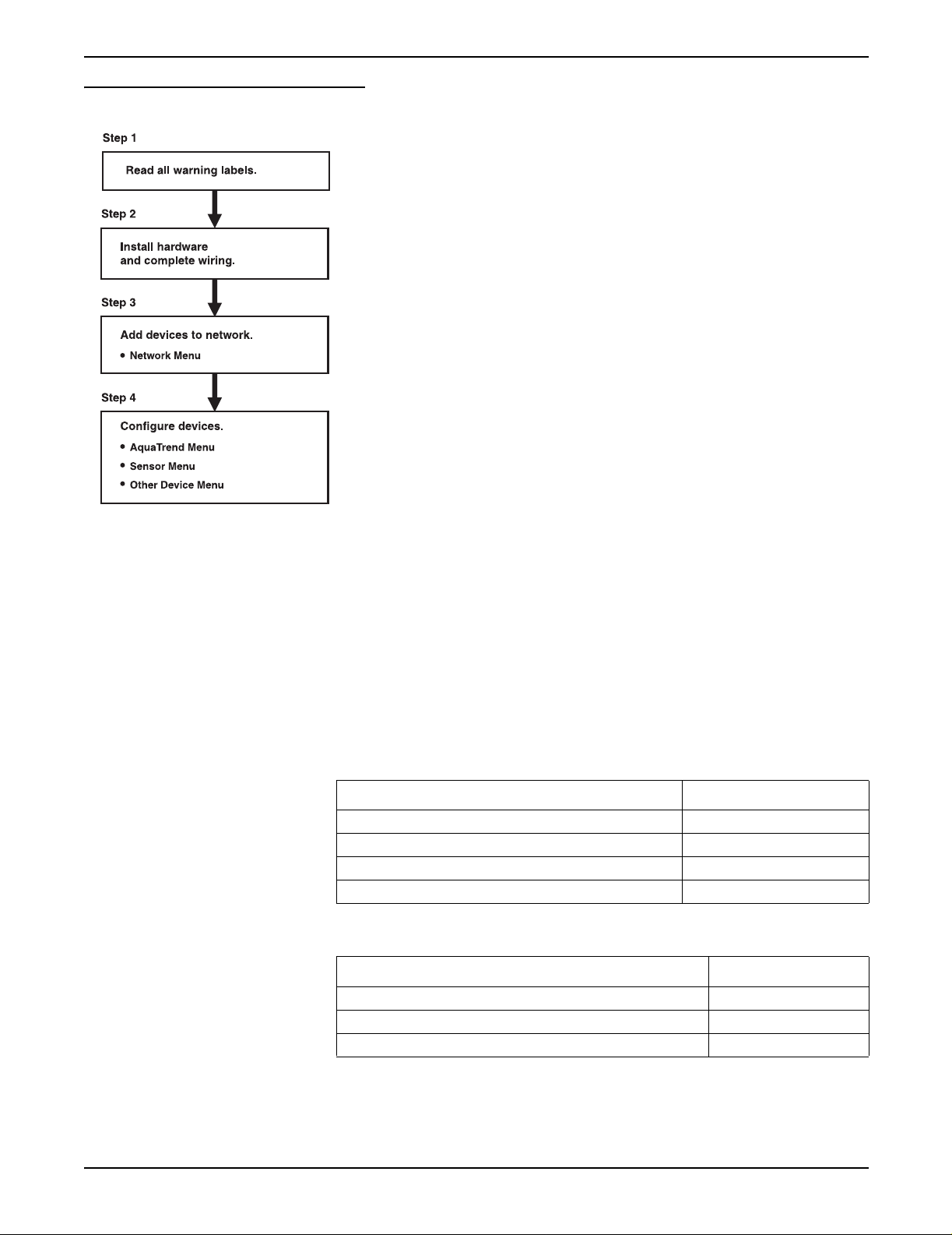
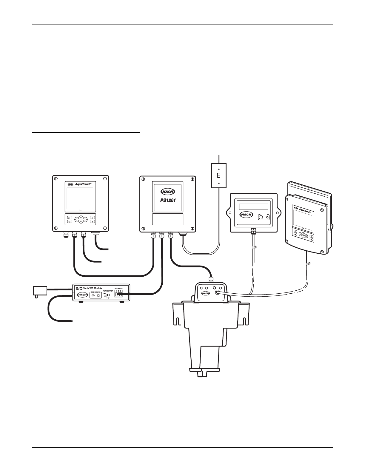
Figure 1 illustrates the basic installation sequence for all AquaTrend Interface
Network devices, except the PS1201 Power Supply, and includes references
to sections of this manual where instructions can be found.
Page 9
51350-18 general description.fm General Description
Section 1
Figure 1 General Installation Information
Refer to Saf ety Prec autio ns on p age 5 and to the sections ref ere nced o n that p age .
Section 5 of this manual.
See the Quick Reference Guide and section 3.1.1 on page 23 of this manual.
Section 3 and Secti on 4
1.3 Unpacking the AquaTrend Interface
After opening the packing carton, remove the insulating foam and identify the
device you have received as an AquaTrend Interface, AquaTrend/SOM, or
Portable AquaTrend Interface. The AquaTrend Interface and AquaTrend/SOM
cartons contain the items listed in Table 1, and the Portable AquaTrend
Interface carton contains the items listed in Table 2. Remove the items from
the carton and verify that no visible damage has occurred during shipment.
Contact Hach Customer Service at 1-800-227-4224 if any items are missing
or damaged.
Table 1 Items Packaged with AquaTrend Interface and AquaTrend/SOM
Item Catalog Number
AquaTrend Interface or AquaTrend/SOM 51200-60 or 51350-60
Bracket, Wall Mount 51409-00
Cable Termination Kit 52156-00
Instruction Manual 51350-18
of this manual.
Page 10
Unpacking the AquaTrend Interface
Table 2 Items Packaged with Portable AquaTrend Interface
Item Catalog Number
Portable AquaTrend Interface with cable assembly 51400-60
Bracket, Wall Mount 51405-00
Instruction Manual 51350-18
51350-18 general description.fm

1.3.1 Optional Equipment
Section 1
Additional items and devices can be obtained to expand the AquaTrend
Interface network system. Some of these items are shown below. A more
detailed description of network devices and network capabilities can be found
in Section 2.
Network Devices
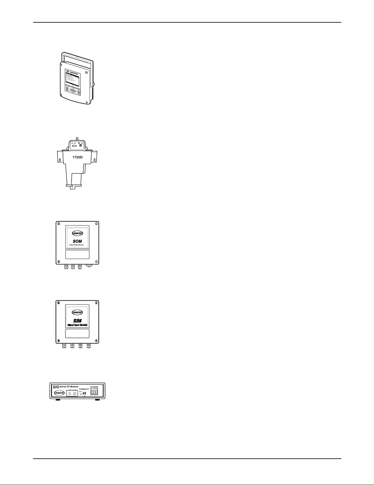
• Serial I/O Module (SIO)
• Signal Output Module (SOM)
• Signal Input Module (SIM)
• Digital Display Module (DDM)
• AquaTrend Interface, AquaTrend/SOM, and Portable AquaTrend
Interface
• Sensors, including 1720D Turbidimeter
Other Equipment
• PS1201 Power Supply
• Floor stand
1.4 Instrument Description
The AquaT rend Interface provides a link between sensors and communication
devices. This networked system provides simplified use of multiple
instruments and requires fewer wiring configurations than systems without a
single digital wiring bus.
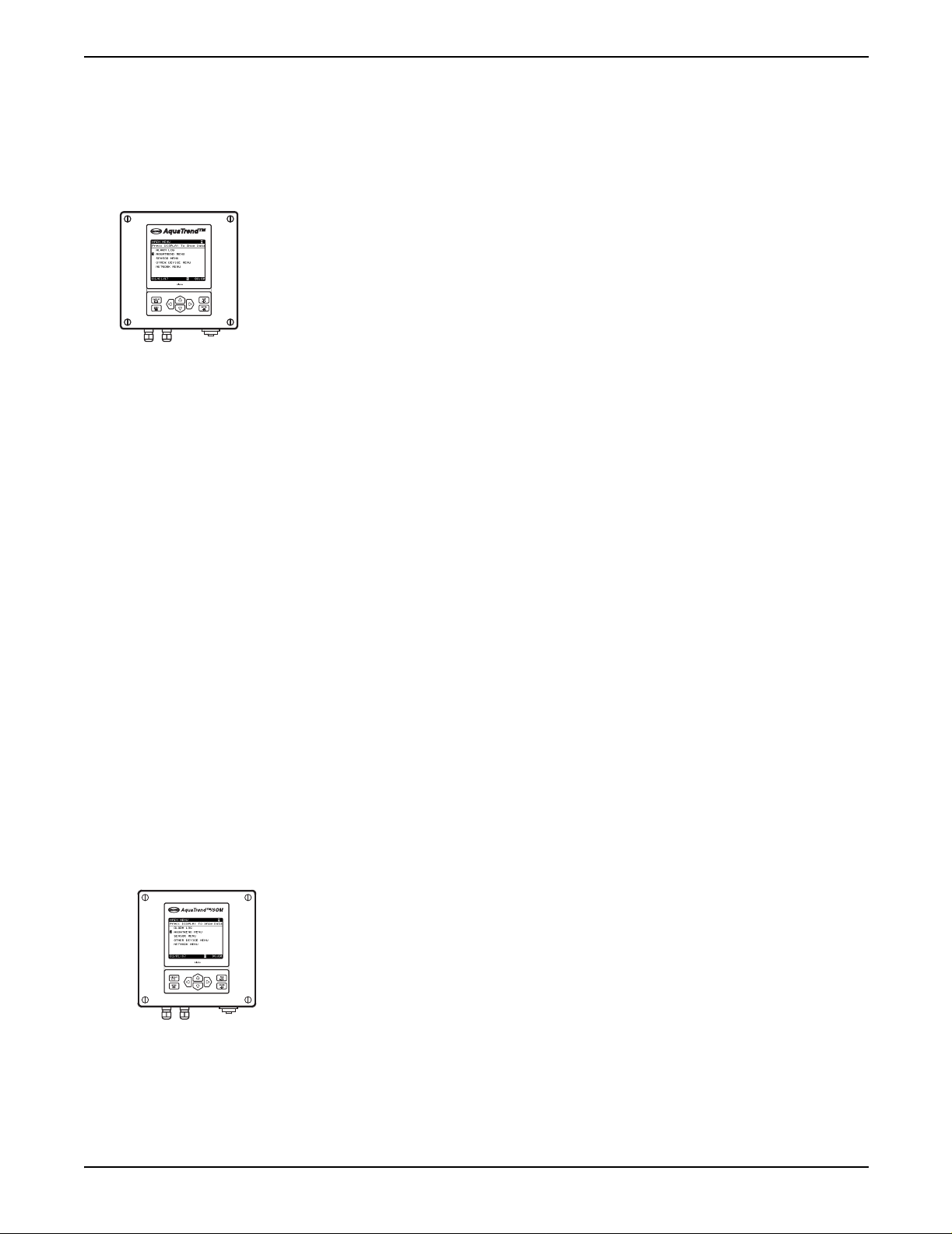
The AquaTrend Interface is available in three different physical configurations:
See section 2.2, De vice Descriptions on page 18 for additional information on
the different configurations.
1.4.1 Operating Environment
Place the AquaT rend Interface in an accessible location, where you can easily
see the display and operate the keypad. The backlit display is visible at 3 ft.
with multiple readings and at 10 ft. with single reading.
• U-bolts for floor stand or pole mounting
• Network repeater
• Cable
• AquaTrend Interface
• AquaTrend Interface with SOM
• Portable AquaTrend Interface
The AquaT rend Interface is designed to operate from 0 to 40 °C (32 to 104 °F)
and 5 to 95% relative humidity, non-condensing. The water-tight design meets
NEMA 4X (indoor) and IEC 529 IP66 enclosure requirements.
Page 11
51350-18 general description.fm Instrument Description
Section 1
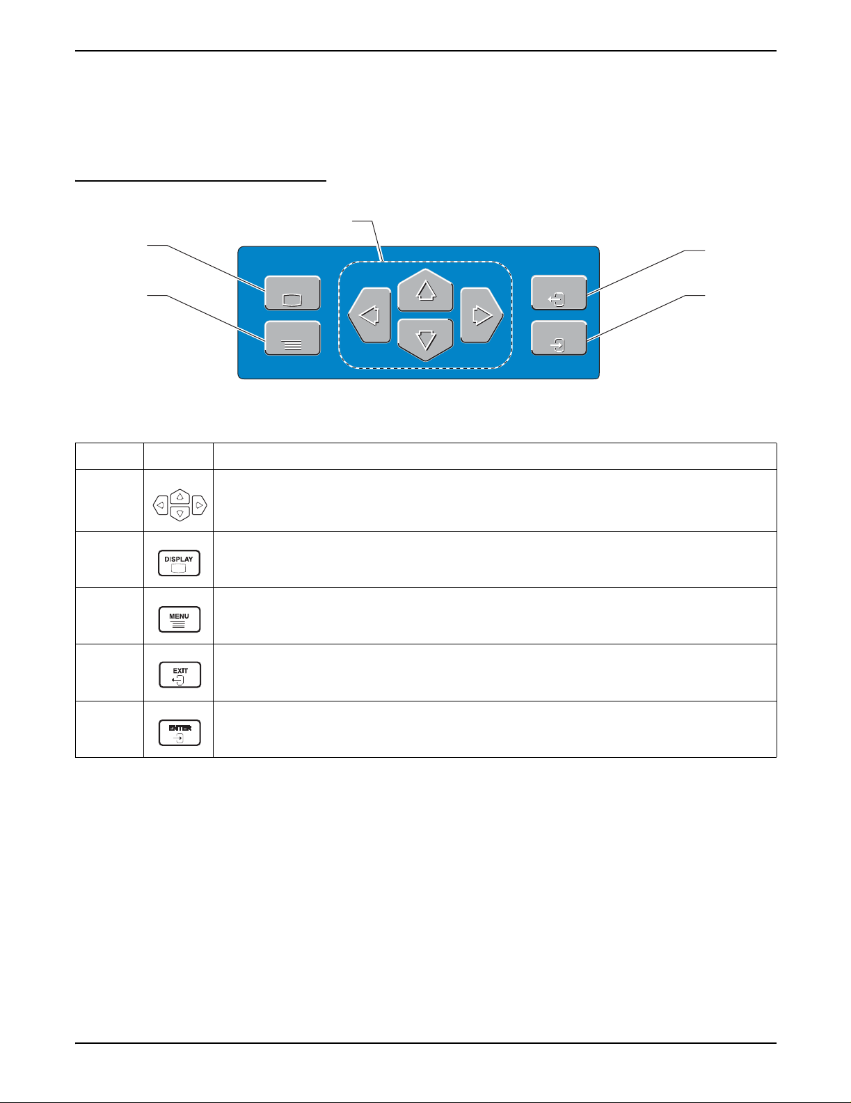
1.4.2 AquaTrend Interface Keypad Description
The AquaTrend Interface keypad is designed for straightforward
navigation through the AquaTrend Interface menus. The keypad contains four
arrow keys, a DISPLAY key, a MENU key, an EXIT key, and an ENTER key.
See Figure 2.
Figure 2 AquaTrend Interface Keypad
1
2
DISPLAY
3
DISPLAY
MENU
MENU
Table 3 AquaTrend Interface Key Functions
EXIT
EXIT
ENTER
ENTER
4
5
Number Key Function of Keys
Allows you to navigate through the various menus , to ch an ge s etti ngs, and to mov e th e cu rso r when
1
observing graph data.
Table 4 summarizes the functions of the arrow keys in each menu view.
2
Displays active data in numeric or graphical format.
Pressing the DISPLAY key toggles between data presented in numerical form and graphical form.
3 Displays the main menu from any menu level or from the data display.
From the Main Menu, pressing the EXIT key provides access to the data display screen.
4
From any other menu level, press the EXIT key to display the previous menu screen.
The EXIT key can also be used to abandon any alphanumeric entry or selection process.
5 Press while in any menu to accept menu options and confirm entries.
The arrow icons and their positions in the arrow field in the top right corner of
the display (item 7 on Figure 4) indicates the active arrow keys. For example,
if three arrow icons are present in the arrow field, pointing up, down, and right,
then the up, down, and right arrow keys can be used while viewing that
screen. Figure 3 shows examples of the screen categories with summaries of
the arrow key functions for each screen category.
Page 12
Instrument Description
51350-18 general description.fm
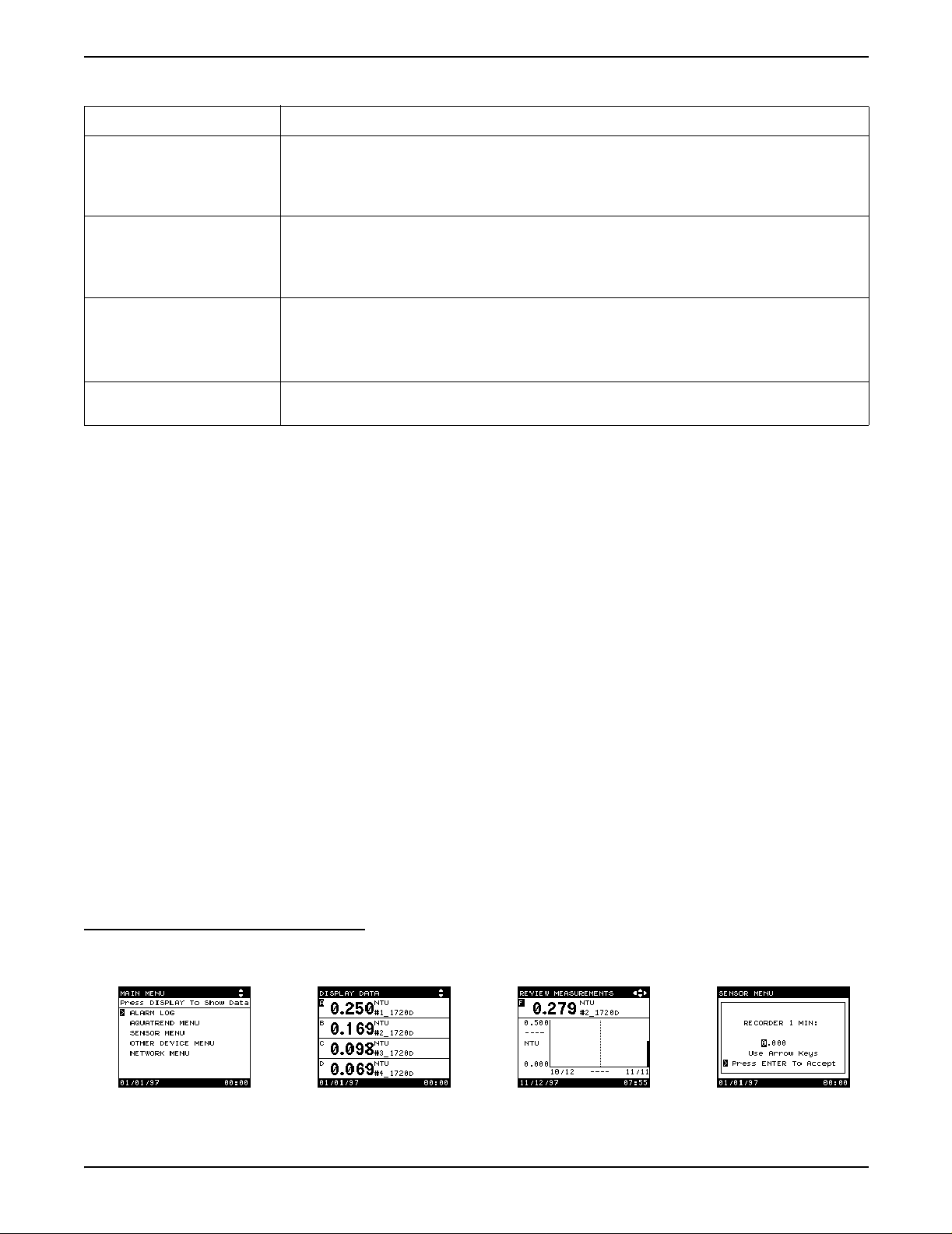
Table 4 Arrow Ke y Functions
Screen Category Function
1. Menu Screen Move the pointer to next (down) or previous (up) item.
For menu s no longer than one page, the po inte r wi ll lo op around from the bottom to the top or
from the top to the bottom.
For multiple-page menus, the pointer will move to the next (down) or previous (up) page.
2. Numeric Data Display
Screen (1 to 8 numeric
readings)
3. Graph Display Screen Up: displays preceding channel graph.
4. Pop-up Entry Screen Increment (up) and decrement (down) currently highlighted character.
Left and Right Arrow: Changes the number of channels shown.
Press the Right Arrow to incr ease the num ber of chann els or press the L eft Arrow to dec rease
the number of channels.
Up and Down Arrow: changes the active channel designation.
Down: displays next channel graph.
Left and Right Arrow: moves curser if it is enabled.
If not enabled, changes the graph time base.
Move highlight to next (right) or preceding (left) character. Loop around at either end.
1.4.3 AquaTrend Interface Display Description
Press the DISPLAY key to alternate between displaying the data in numeric
and graphical mode.
Section 1
• Viewing data in numeric mode allows you to display from one to eight
measurements at the same time. When additional measurements are
shown on the screen, less information is displayed for those
measurements.
• Viewing data in graphical mode allows you to see a history of sensor
readings over the last 2 hours, 8 hours, 30 hours, 7 days, or 30 days,
depending on the graph time base selected. However, the AquaTrend
Interface displays data for only one channel at a time in the graphic mode.
For details on selecting the number of numeric channels of data shown and
the graph time base, see section 3.5.1 and section 3.5.2.
Press the MENU key to return to the Main Menu at any time. T o return to data
display mode, press either the EXIT or DISPLAY keys.
AquaTrend Interface screens appear in several different formats.
Sensor measurements are attached to separate channels, labeled A-P,
on the AquaTrend Interface. Refer to Figure 4 and Figure 5 for descriptions
of each field.
Figure 3 AquaTrend Interface Display Categories
1. Menu Screen 2. Numeric Data
Display Screen
51350-18 general description.fm Instrument Description
3. Graph Display Screen 4. Pop-up Entry Screen
Page 13
Section 1
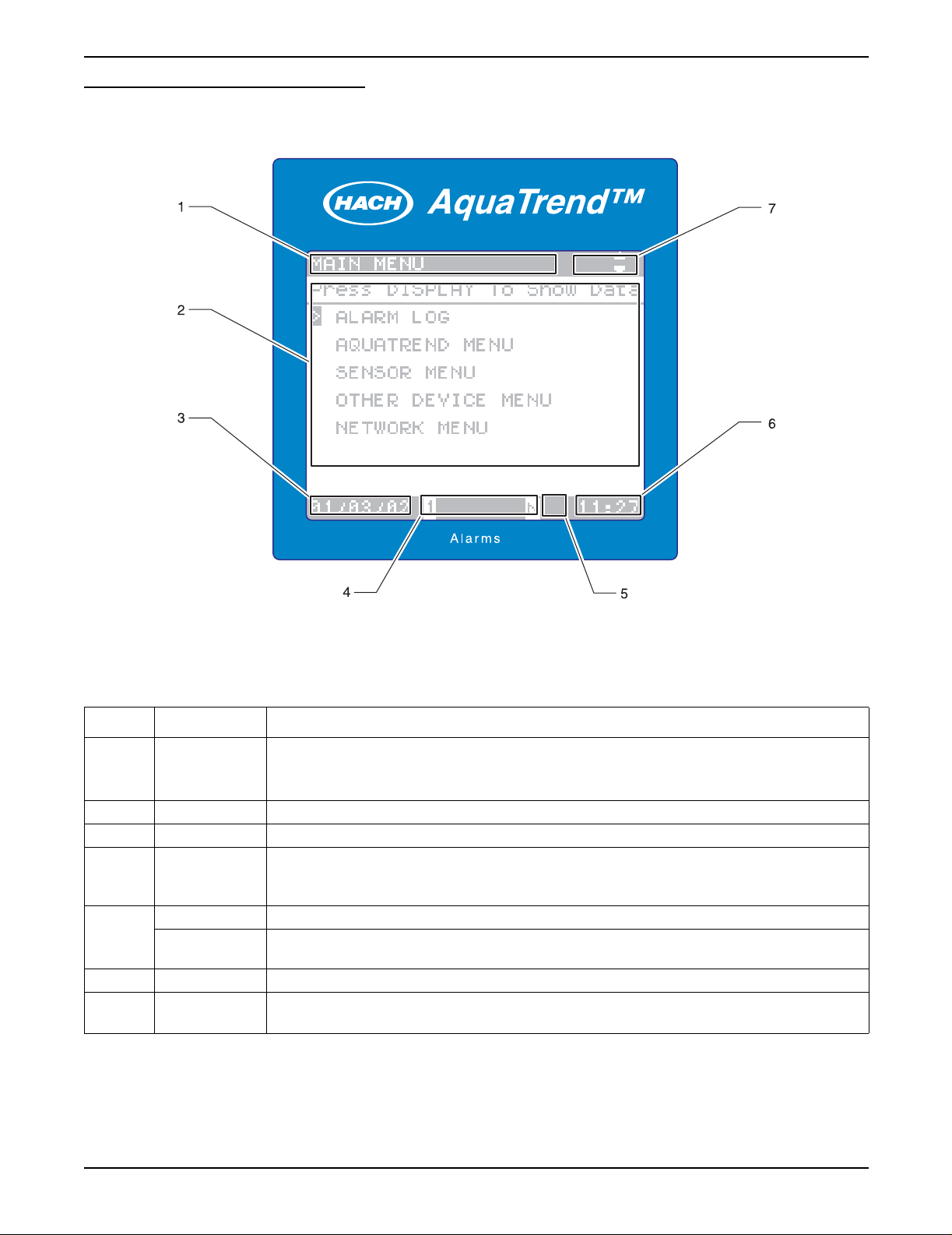
Figure 4 AquaTrend Interface Menu and Numeric Data Display Fields
Table 5 AquaTrend Interface Menu and Numeric Data Display Fields
Number Field Information Shown in Display Field
Numeric Data display: shows DISPLAY DATA
1 Status Bar
2 Text/Data Numeric data (1- 8 channels), graphical data, menus, and pop up boxes appear here.
3 Date Current date
4Alarms
Security Icon When displayed, indicates a security level of Partial or Total
5
6 Time Current time displayed as military time (24 hour clock).
7
Hourglass Icon
Navigation
Arrow
Main menu: shows MAIN MENU
Lower menus: shows top level menu (main menu item)
Numbers that appear here, 1 through 8, correspond to the sensor with active alarms. If “N”
appears in this field, a Network alarm is active. If no indicators appear in this field, no system
alarm is active. See section 4.2 on page 47 for information on reviewing alarms.
When displayed, indicates the datalog is completing a change.
The keyboard buffer is cleared when the icon disappears.
Direction of these arrow icons correspond to active arrow keys for each screen.
Page 14
Instrument Description
51350-18 general description.fm
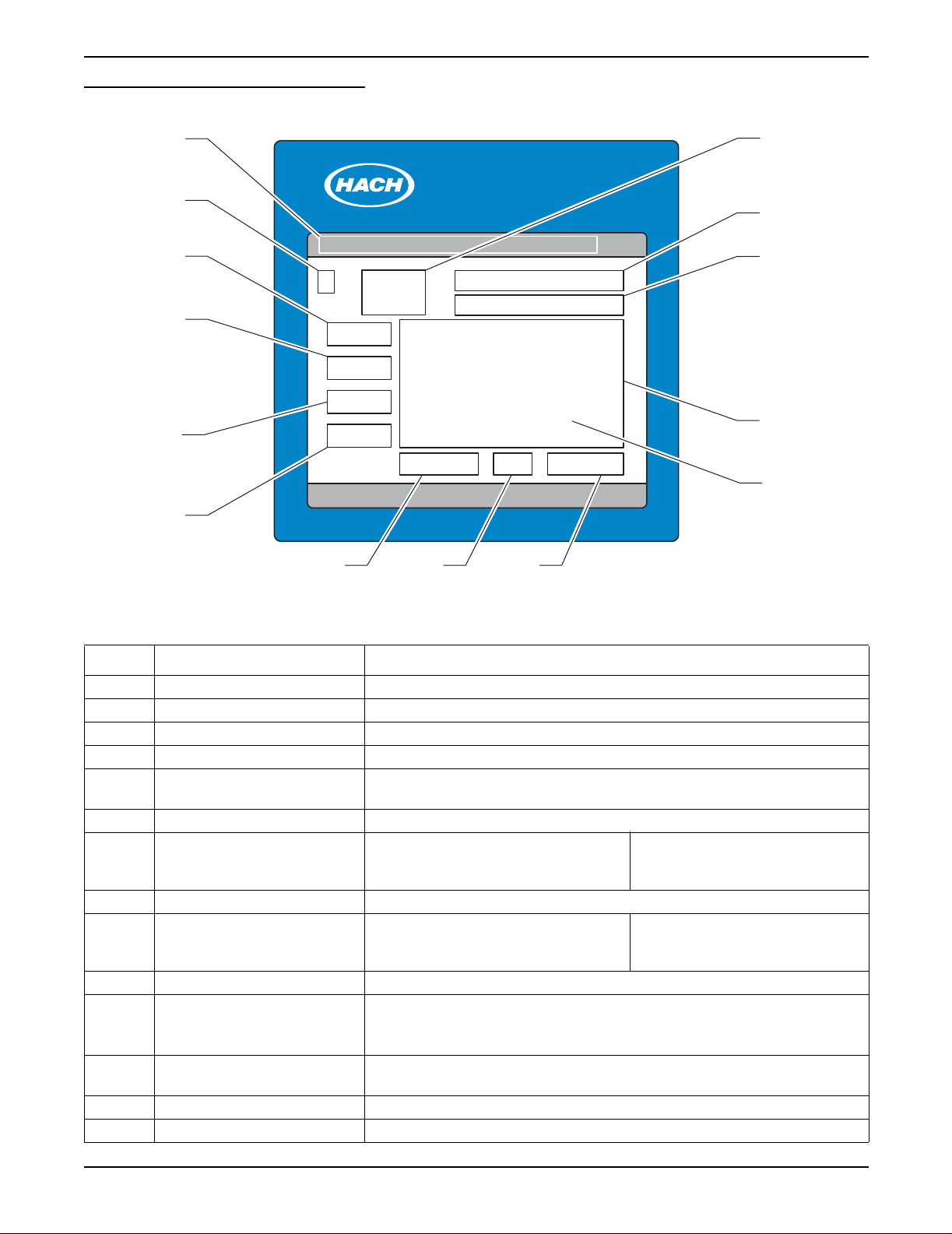
Figure 5 AquaTrend Interface Graph Fields
Section 1
1
2
3
4
5
6
AquaTrend™
Alarms
987
14
13
12
11
10
Table 6 Graph Field Descriptions
Number Field Information Shown in Graph Field
1 Status Bar Shows REVIEW MEASUREMENTS
2 Channel assignment Channel number of the measurement shown in the graph
3 Graph Da ta — Y-axis upper limit Upper numeric limit of trend graph data. (Ymax)
4 Cursor Y-data Y value of data at cursor position
5 Units/Species
6 Graph data — Y-axis lower limit Lower numeric limit of trend graph data (Y-min)
7 Graph time — X-axis low er li mit Lo wer time limit (oldest data).
8 Cursor Time/Dat e Time or date value of data at cursor position
9 Graph time — X-axis upp er lim it Curre nt time (lates t data) .
10 Graph Cursor Retrieves value of data at cursor position
11 Graph Area
12 Sensor name
13 Units and chemical form Units and chemical form of the measurement on the channel
14 Current Data Most recent measurement (same as numeric display)
Units and chemical form (where appropriate) of the measurement on the
displayed channel
If data is being reviewed in the
24 hour or 30 day mode, this field is
replaced with the date.
If data is being reviewed in the
24 hour or 30 day mode, this field is
replaced with the date.
Graph of 60 minutes, 8 hours, 24 hours, 7 days, or 30 days of data.
These settings are selectable in the DISPLAY SETUP menu (section 3.5.2 on
page 32).
Depending on the sensor type and configuration, the display shows
measurement name or the sensor location, or a combination of both.
Page 15
51350-18 general description.fm Instrument Description

Section 1
1.5 AquaTrend Interface Menu Organization
The AquaTrend Interface main menu can be accessed at any time by
pressing the MENU key. The main menu categories are described in the
following sections.
1.5.1 Alarm Log
The alarm log menu provides a historical account of sensor specific alarm
information as well as AquaTrend Interface network alarm information.
1.5.2 AquaTrend Interface Menu
The AquaTrend Interface menu provides access to AquaTrend Interface
display and status settings. Display settings, language selection, time and
date settings, and security settings all reside in the AquaTrend Interface
menu. Access this menu to change the way information appears on the
AquaTrend Interface screen.
1.5.3 Sensor Menu
The sensor menu contains all sensor specific information including
calibration, alarm and recorder setup, measurement options, and sensor
diagnostics. The contents of this menu will change based on the sensor you
are working with. Since all of these menu items are stored within the sensor,
they are designed to be sensor specific. Access this menu to change sensor
settings or information.
1.5.4 Other Device Menu
1.5.5 Network Menu
The other device menu contains information specific to accessory devices
that are not sensors. Such examples include Signal Output Modules, Serial
I/O Modules and Digital Display Modules. Access this menu to change
settings or information for non-sensor devices.
The network menu contains information specific to performing network
operations. This includes adding, removing, and replacing devices on the
network. In addition, it contains menu items needed to establish
communications between devices. For example, once a sensor and Digital
Display Module are added to the system via the AquaTrend Interface, you
must instruct the sensor to attach its reading to the Digital Display Module.
Because many underlying network connections occur when performing
network operations, it is important to have all existing devices on the network
powered and operating normally when network operations are conducted.
Section 3 and Section 4 of this manual describe how to use these menus
together to build and configure your network.
Page 16
AquaTrend Interface Menu Organization
51350-18 general description.fm
Section 2 Aquatrend® Interface Network
2.1 Network Description
This section describes requirements and options for setting up the AquaTrend
Interface Network System. A “network” is the connection of one or more
devices (of which at least one is a sensor) to a Master AquaTrend Interface.
This Master AquaTrend Interface serves as the network control panel.
Devices can include Signal Output Modules (SOM), Digital Display Modules
(DDM), Serial I/O Modules (SIO), Remote AquaTrend Interf aces and
Portable AquaTrend Interfaces.
Figure 6 shows an example of a single-sensor AquaTrend Interface Network
System. An example of a multi-sensor system is shown in Figure 7.
Figure 6 Single-Sensor AquaTrend Interface Network
115 / 230 VAC
Power In
Customer Supplied
ON/OFF Switch
ON
OFF
expansion
AC Power
Spare -
open for
DISPLAY
MENU
EXIT
ENTER
Relays
4-20mA Outputs
RS232 Computer or Printer Interface
Power Supply 12V DC
Network Connection Module
1720D
DIGITAL
DISPLAY MODULE
CONFIGURE
D
I
S
P
M
E
N
Either the
DDM or the
Portable AquaTrend
L
A
Y
U
E
X
I
T
E
N
T
E
R
Each sensor (i.e., the 1720D Turbidimeter) manual provides instructions for
setup of the single-sensor network. Each of the other device manuals,
(AquaTrend/SOM, AquaTrend Interface, Digital Display Module, Serial I/O
Module, Signal Input Module and Signal Output Module) provides setup
instructions for their components.
Section 2.3
describes the maximum
number of devices that can be managed by one Master AquaTrend Interface
on a system.
51350-18 Aquatrend Interface Network.fm Aquatrend
®
Page 17
Interface Network
Section 2
2.2 Device Descriptions
2.2.1 AquaTrend Interface Module
The two primary functions of the AquaTrend Interface are network
management and data display. Network management functions are required
only when performing modifications to the network such as adding or
removing devices. Multiple AquaTrend Interfaces (up to nine) can exist on a
network at any given time. Remote AquaT rend Interfaces serve to display data
from one or more sensors and access sensor menus.
• Master AquaTrend Interface – Acts as the main network data control
center for setup and operation of the network. The network can contain as
many as nine AquaTrend Interfaces but only one can be the Master
AquaTrend Interface. Only through the Master AquaTrend Interface can
network operations be performed.
• Remote AquaTrend Interface – Any AquaTrend Interface on a network
that is not a Portable or Master AquaTrend Interface. Remote AquaTrend
Interfaces can control and monitor all sensors on the network. Remote
AquaTrend Interfaces cannot perform network operations such as adding
and removing devices.
• Portable AquaTrend Interface – Mobile device designed for set up and
calibration of sensors already on the network. Portable AquaTrend
Interfaces can communicate with one sensor at a time and cannot
perform network operations. See section 2.2.3 and 5.2 for more
information about the Portable AquaTrend Interface.
All AquaTrend Interfaces have the capability of functioning as a Master or
Remote however, only the Master AquaTr end Interface is allowed to perform
network management functions. All AquaTrend Interfaces are shipped from
the factory in an undefined (neither Master or Remote) state. When an
individual AquaTrend Interface is defined as the Master, any other AquaTrend
Interface on the network must be defined as a Remote. An AquaTrend
Interface can be redefined (i.e., Remote to Master or Master to Remote);
however , e xisting network connection information will be lost. After changing a
Remote to a Master AquaTrend Interface, you must rebuild the network and
reestablish communications between devices.
2.2.2 AquaTrend/SOM with Integrated Signal Output Module
The AquaT rend/SOM Module is a combined AquaTrend Interface and SOM in
one enclosure. See section 2.2.1 for information concerning the functions and
options for the AquaTrend Interface portion of the combined AquaTrend/SOM
and section 2.2.5 for more details about the SOM.
Page 18
Device Descriptions
51350-18 Aquatrend Interface Network.fm
2.2.3 Portable AquaTrend Interface Module
The Portable AquaTrend Interface can access sensor menus for setup and
calibration but cannot perform network management functions. The Portable
AquaTrend Interface communicates directly to the sensor that it is attached to
without interpreting network commands from the Master AquaT rend Interface.
Once a network is configured using a Master AquaTrend Interface, the
Portable AquaTrend Interface can be used to display and log data from that
sensor in the absence of a Master AquaTrend Interface.
2.2.4 Sensor
The sensor, such as the 1720D Turbidimeter (shown at left), is the
device that analyzes the sample. Sensors may or may not contain an
AquaTrend Interface.
Section 2
2.2.5 Signal Output Module (SOM)
Each SOM provides two relays, each with normally open and normally closed
contacts rated at a maximum of 5A/250 VAC, and two analog outputs,
selectable through the AquaTrend Interface keypad at either 4-20 or 0-20 mA.
Signal Output Module functionality can be provided either in an
AquaTrend/SOM or in a separate Signal Output Module. See the
Output Module Manual
2.2.6 Signal Input Module
The Signal Input Module (SIM) is configured as a sensor on the network
system and provides two 4-20mA analog inputs. These inputs can be used to
bring measurements from non-networked sensors into the network. The SIM
allows the user to set the value for zero and full-scale inputs and to define the
measurement names, units, and species. Two configurable setpoint alarms
can be set to trigger relays in a Signal Output Module. Refer to the
Input Module (SIM) Manual
2.2.7 Serial I/O Module (SIO)
The AquaTrend Interface allows the review of data collected over the last 60
minutes, 24 hours, or 30 days. To download the data to a computer or printer,
a Serial I/O (SIO) Module must be installed. The SIO provides two-way
communication with a computer (PC) or one-way communication with a
printer. Use an SIO to permanently log measurement and diagnostic data to a
printer or computer. See the
for detailed information.
for additional information.
Serial I/o Module Manual
Signal
Signal
for detailed information.
Page 19
51350-18 Aquatrend Interface Network.fm Device Descriptions

Section 2
2.2.8 Digital Display Module (DDM)
The Digital Display Module (DDM) is an eight-character display that can be
attached to sensors to provide a local digital reading. Once the display is
added to the network and assigned to the sensor by the Master AquaTrend
Interface, it will automatically display data from the sensor. For sensors that
have multiple parameters (measurements), you can choose which parameter
you want to display on the DDM. See the
detailed information.
2.2.9 Repeater Module
The AquaTrend Repeater module is a physical layer repeater used to extend
the length of the AquaTrend Network by a maximum of 500 meters. A total of
three such devices can be installed on the AquaTrend Network to extend the
total length of the network to 2000 meters.
2.3 Network Design
Based on Wiring Topologies on page 83, determine the appropriate
configuration for your operation by considering the following criteria;
descriptions of each device is given in section 2.2.
Digital Display Module Manual
for
Table 7 Maximum Network Capabilities
Device
Signal Output Module (SOM) 8
Serial I/O Module (SIO) 2
Digital Display Module (DDM) 8
Sensors (A SIM is seen by the network as a sensor.
Maximum sensors + SIMs = 8)
AquaTrend Interface 1 Master, 8 Remotes
Note: All AquaTrend Interfa ces on a
system display measurements and
menus, but only the Master
AquaTrend Interface can perform
network operations through the
Network Menu.
The system can contain as many as nine AquaTrend Interfaces but only
one can be the Master AquaTrend Interface. Each AquaTrend Interface
is programmed in an undetermined state when shipped from the factory
and must be designated as a Master or Remote when initially attached to
the network.
Number of devices that can be maintained on one
AquaTrend Interface Network
8
If more than one AquaTrend Interface is to be attached to the network,
the Master AquaTrend Interface will be designated before other
AquaTrend Interfaces are added. Additional AquaTrend Interfaces will be
designated as Remotes.
Select the number of PS1201s based on the wattage needed and the
distance between the power supplies and the devices. Each PS1201
Power Supply provides 25 watts. Available devices and their wattages are
listed below and in the PS1201 manual.
Page 20
Network Design
If a system larger than 35 nodes is needed, refer to the information on
assigning subnet addresses in Appendix A Use of Subnets on page 75.
51350-18 Aquatrend Interface Network.fm

Table 8 Wattage Requirements for AquaTrend Interface Devices
Device Power Required (watts)
AquaTrend/SOM 5
AquaTrend Interface 2
Portable AquaTrend Interface 2
Digital Display Module (DDM) 2
Signal Output Module (SOM) 3
Signal Input Module (SIM) 2
Serial I/O Module (SIO) Provides its own AC (wall plug) power supply.
1720D Turbidimeter (sensor) See the 1720D Turbidimeter manual
Section 2
Page 21
51350-18 Aquatrend Interface Network.fm Network Design
Section 2
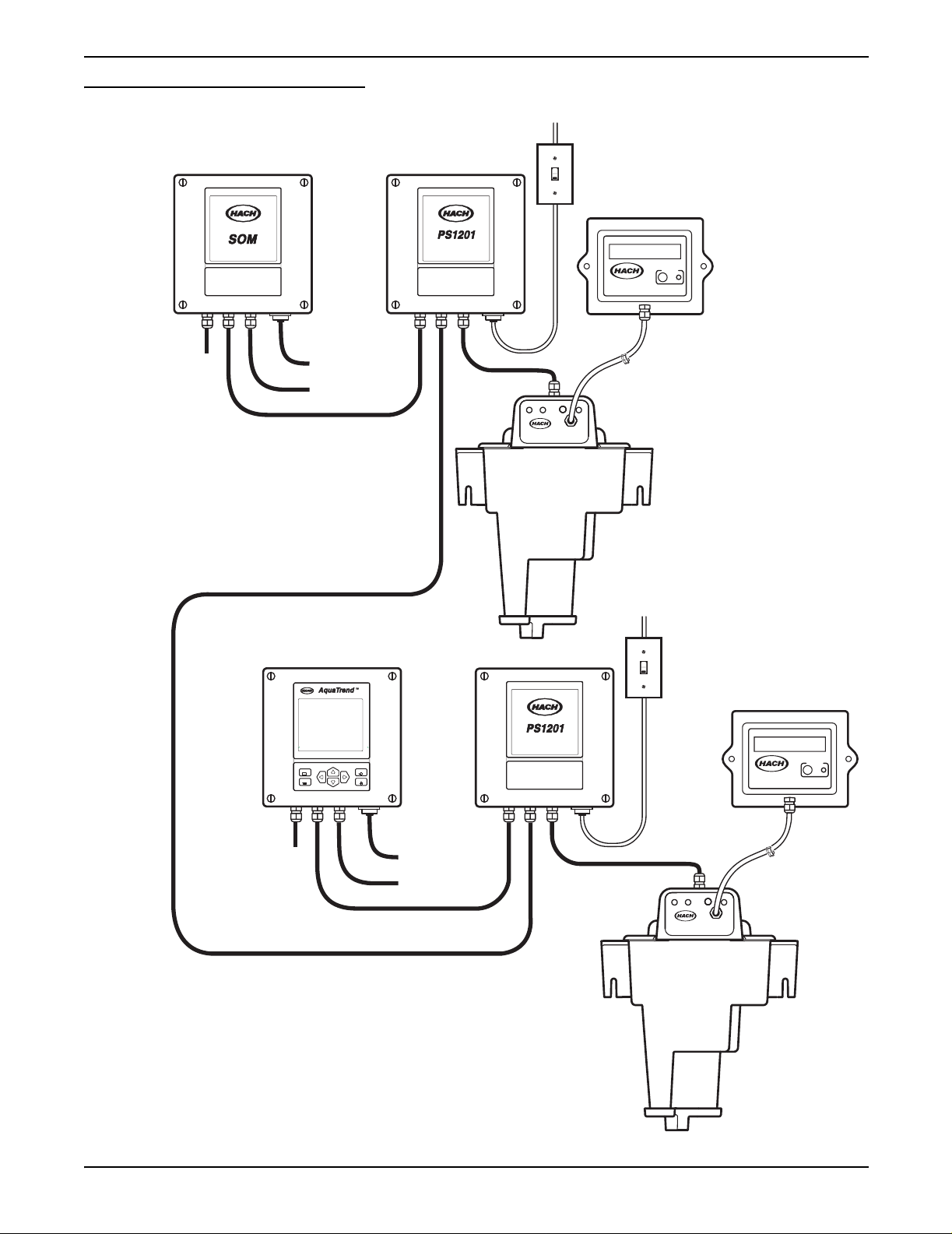
Figure 7 Example of Multi-Sensor Setup
115 / 230 VAC
ON
Power In
OFF
Customer Supplied
ON/OFF Switch
Signal Output Module
For
Network
Expansion
Network Communications Cable
Relay Contacts
4-20 mA Outputs
Power Supply 12V DC
Network Connection Module
1720D
DIGITAL
DISPLAY MODULE
ON
OFF
CONFIGURE
115 / 230 VAC
Power In
Customer Supplied
ON/OFF Switch
Page 22
Network Design
For
Network
Expansion
Power Supply 12V DC
Network Connection Module
DISPLAY
MENU
EXIT
ENTER
DIGITAL
DISPLAY MODULE
CONFIGURE
Relay Contacts
4-20 mA Outputs
1720D
51350-18 Aquatrend Interface Network.fm
Section 3 Initial AquaTren d Setup
3.1 Identifying the Master AquaTrend
Every AquaT rend® Interface Network System requires a network manager
to perform network operations, such as adding or removing devices.
The AquaTrend and AquaTrend with SOM can perform network
management functions when set to Master AquaTrend status through the
AquaTrend software; however, only one Master AquaT rend can be present on
the network at a time. All other AquaTrends must be set to Remote AquaT rend
status. Care should be taken when determining the location of the
Master AquaTrend Interface.
Every AquaT rend Interface is shipped in an undefined state. When connecting
only one AquaTrend Interface to the network, it must be designated as the
Master AquaTrend Interface.
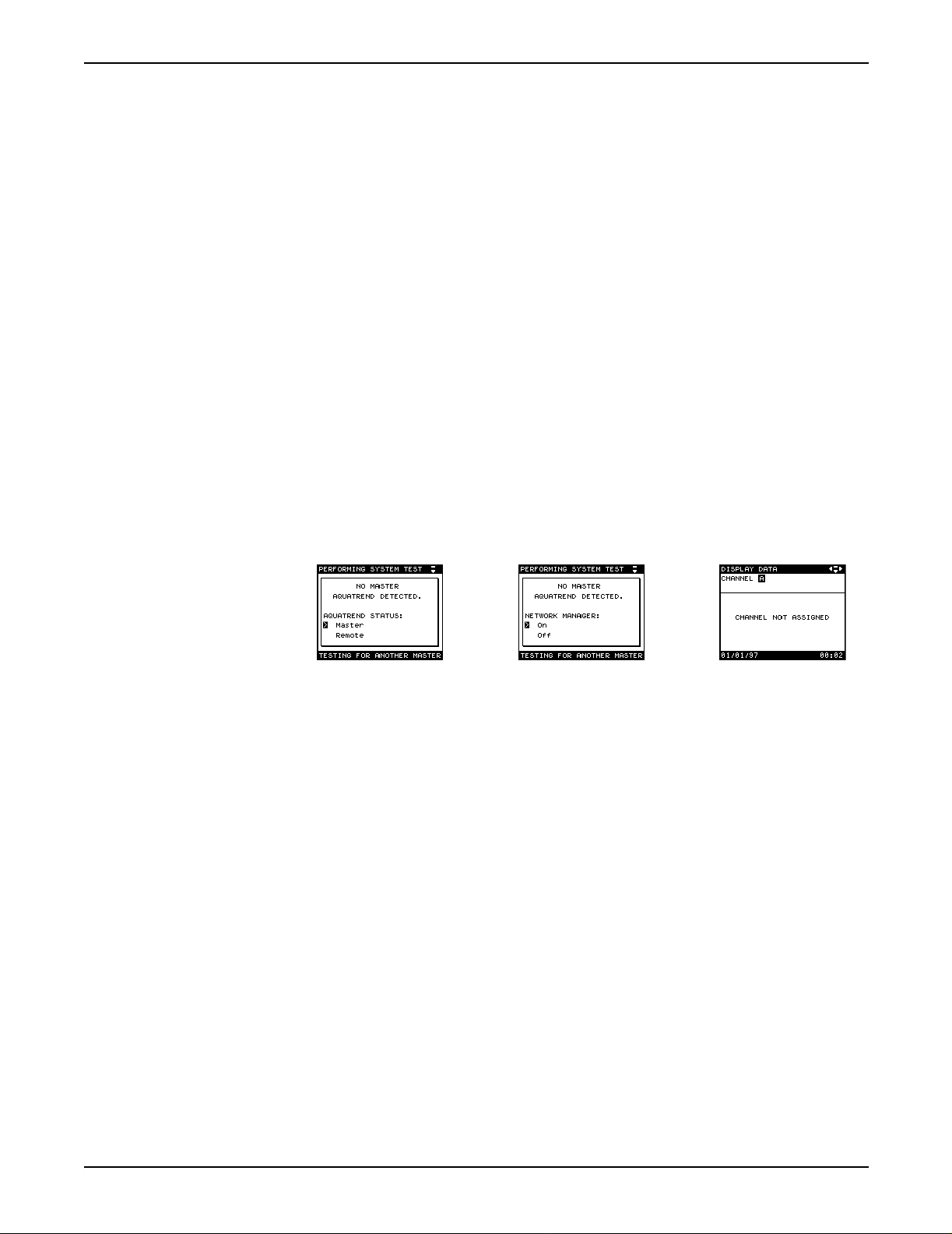
Set the system AquaTrend Interface to Master status as follows:
1. Upon initial power-up, select MASTER and press the ENTER key.
2. Press Enter to select Network Manager to ON. After a brief delay, the
display will show the data display screen (CHANNEL NOT ASSIGNED).
3. Press the Menu key to proceed to the Main Menu.
3.1.1 Adding Remote AquaTrend Interfaces to the Network
Upon power up, new AquaTrend Interfaces on the network will search for a
Master AquaTrend Interface. (The exception is when installing an AquaTrend
Interface that has previously been installed as part of another AquaTrend
network. In this case, the AquaTrend that is new to this network will not
automatically check for a master. To force it to check, press the EXIT key
when instructed to install the remote from the network manager.)
Once a master is identified, the additional AquaTrend Interfaces will assume
remote AquaT rend Interface status and can be added to the network using the
instructions in section 3.4.2, Adding a Device to the Network.
The Master AquaTrend Interface should not be changed to a remote unless
you want to change the location where network operations are performed.
A change from Master to Remote AquaTrend Interface status will erase all
network information, requiring you to restore network connections.
See section 3.12 on page 41.
Page 23
51350-18 Initial Aquatrend Setup.fm Initial AquaTrend Setup
Section 3
3.2 Language Setting
3.3 Time/Date Setting
3.3.1 Setting the Time
English is the default language of the AquaTrend Interface Network System.
To display another language, follow the instructions below:
1. Press the MENU key to begin at the Main Menu.
2. Use the up or down arrow key to select AQUATREND MENU and
press ENTER.
3. Select LANGUAGE and press ENTER.
4. Use the up or down arrow keys to move the pointer to the desired
language and press ENTER. All screens will be displayed in the
selected language.
Verify the time and date are correct. If necessary, change them as instructed
in the following sections.
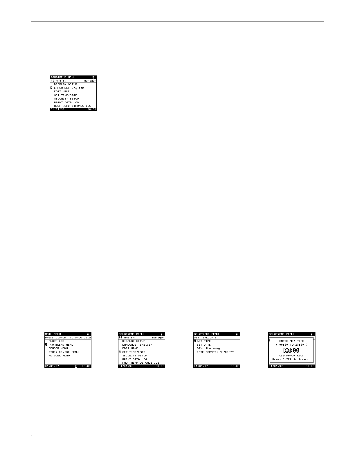
1. Press the MENU key to access the Main Menu.
2. Use the up or down arrow key to move the pointer to AquaTrend Menu
and press ENTER.
3. Select the SET TIME/DATE option and press ENTER.
Note: The AquaTrend Interface uses a 24-hour clock (military time), so there is no
selection for a.m. and p.m. For example, if the current time is 4:00 p.m., enter the
24-hour format equivalent of 16:00.
a. Select SET TIME.
b. A pop-up box will prompt you to enter the new time. The numbers
representing the hour will be highlighted.
c. Press the up arrow key to increase the hour setting and press the
down arrow key to decrease the setting.
d. When the proper hour is displayed, press the right arrow key and set
the minutes as in step c above.
e. Press ENTER to accept the displayed value, or press EXIT to cancel.
Page 24
Language Setting
51350-18 Initial Aquatrend Setup.fm
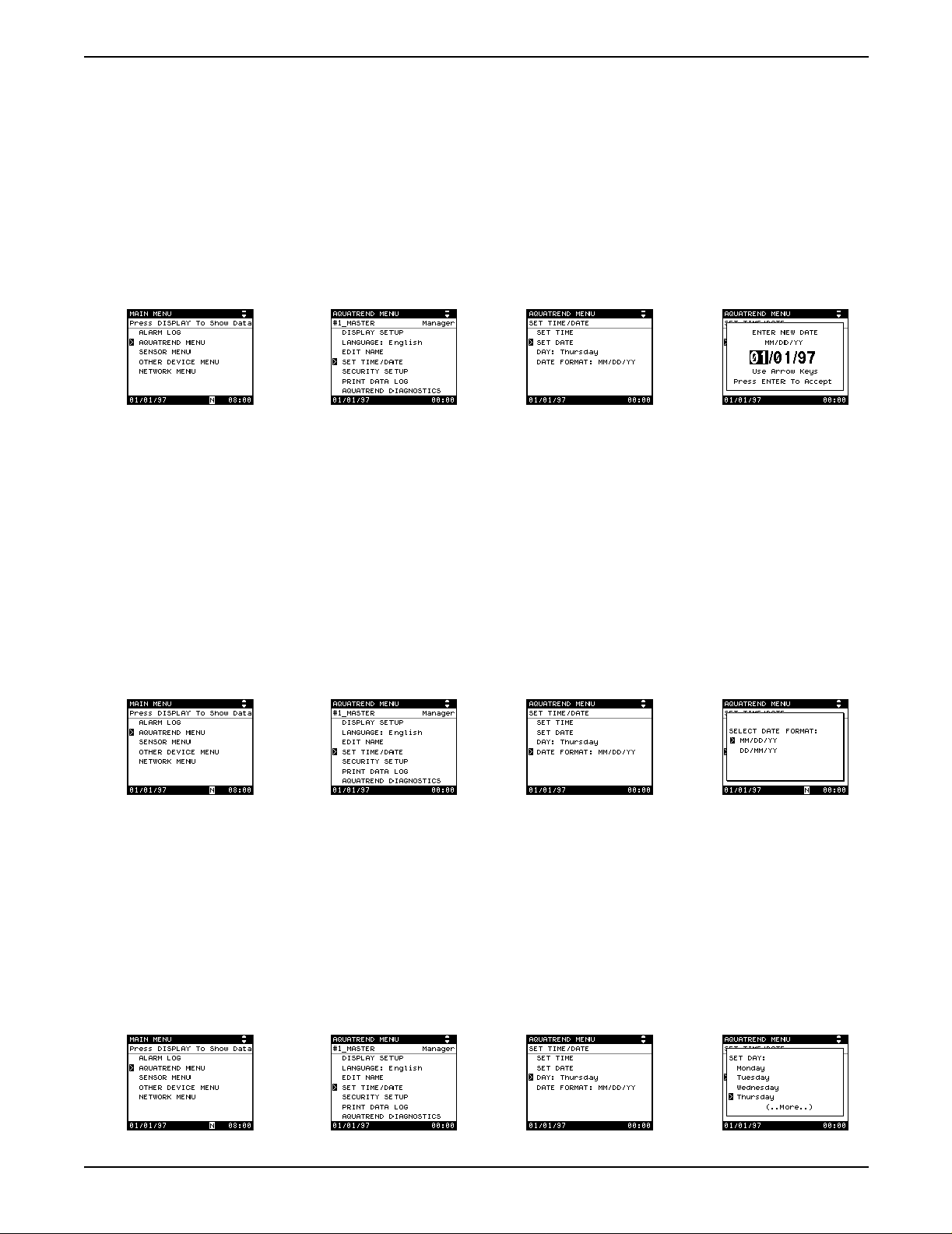
3.3.2 Setting the Date
Section 3
1. Press the MENU key to access the Main Menu.
2. Use the up or down arrow key to move the pointer to AquaTrend Menu
and press ENTER.
3. Select the SET TIME/DATE option and press ENTER.
a. Select t he SET DATE option and press ENTER.
b. A pop-up box will prompt you to enter the new date.
c. Press the up and down arrow keys to increment through the available
digits. Press the right or left arrow key to move to another character
field wi thin the date.
d. When the proper date is displayed, press ENTER to accept or press
EXIT to cancel.
3.3.3 Changing the Date Format
a. To change the date format, select DATE FORMAT from within
the Set Time/Date Menu. A pop-up box will appear requesting
SELECT DATE FORMAT.
b. Select the preferred date format – MM/DD/YY is month/day/year, and
DD/MM/YY is day/month/year.
3.3.4 Setting the Correct Day of the Week
The internal calendar programs the day of the week to correspond to the set
date. If it is necessary to change the day, proceed as follows:
a. To change the day of the week, select DAY from within the
SET TIME/DATE menu. To change the day setting, which shows the
current day of the week, select DAY.
b. Mov e the p ointer t o the correc t da y and pres s the ENTER ke y. The day
will move forward automatically with the clock at 24:00 hours.
Page 25
51350-18 Initial Aquatrend Setup.fm Time/Date Setting
Section 3
3.4 Network Setup
3.4.1 Single Sensor System
A “network” is the connection of one or more devices (at least one must be a
sensor) to one or more AquaTrend Interfaces. A “device” can be an additional
1720D sensor, Digital Display Module (DDM), Serial I/O module (SIO), Signal
Output Module (SOM), or a remote AquaTrend Interface.
Up to eight sensors, eight Digital Displays, eight remote AquaTrend
Interfaces, eight Signal Output Modules, two Serial I/O Modules and all
necessary power supplies may be attached to the network.
The two procedures for adding device(s) to the network are presented in
section 3.4.1 and section 3.4.2.
Use this feature when installing a complete system with no more than
(1) Sensor (the 1720D Turbidimeter is being used in this example),
(1) Master AquaTrend Interface, (1) SOM (as an integral part of an AquaT rend
Interface or as a separate device), (1) SIO, (1) DDM, and (1) remote
AquaTrend Interface. During this procedure, the default device settings are
accepted and sensor measurements are automatically assigned to
appropriate channe ls.
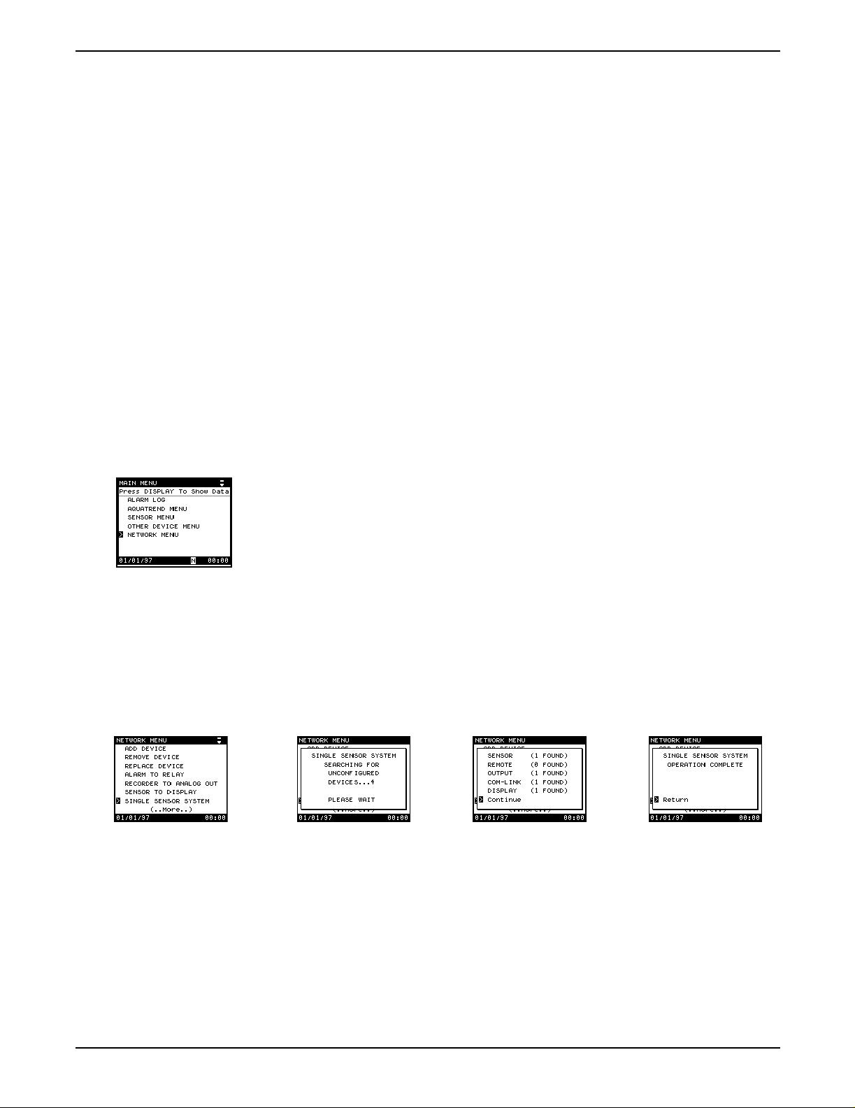
1. Press the MENU key to access the Main Menu.
2. Choose Network Menu.
3. Select SINGLE SENSOR SYSTEM.
A pop-up box will appear stating SINGLE SENSOR SYSTEM
SEARCHING FOR UNCONFIGURED DEVICES.
4. If the system is correctly installed, the display will next show a pop-up box
listing all devices found. Press ENTER to install the single sensor system.
5. After configuration, the display will show OPERATION COMPLETE.
6. Press the DISPLAY key to show sensor data.
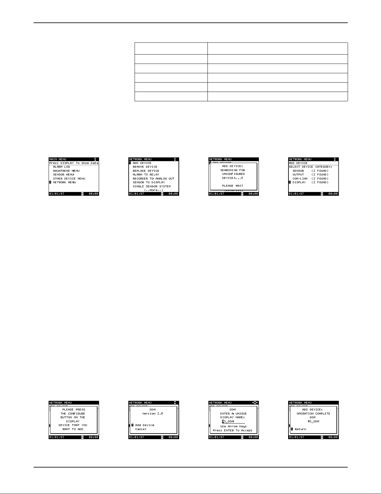
3.4.2 Adding a Device to the Network
Table 9 presents available device types. Follow the procedure below to add a
device. Repeat as many times as is necessary to add all needed devices to
the network.
Page 26
Network Setup
1. Press the MENU key to start from the AquaTrend Interface Main Menu.
2. Press the down arrow key to move the pointer to NETWORK MENU and
press ENTER.
51350-18 Initial Aquatrend Setup.fm
Section 3
Table 9 AquaTrend Interface Device Types
Device Type Devices
Sensor 1720D Turbidimeter, any APA6000 Analyzer or SIM
Com-Link Serial I/O Module (SIO)
Outputs Signal Output Module (SOM)
AquaTrend Interface Remote AquaTrend Interface
Display Digital Display Module (DDM)
3. Select ADD DEVICE and press ENTER.
A pop-up box will show: SEARCHING FOR UNCONFIGURED
DEVICES...PLEASE WAIT.
4. If only one unconfigured device type is connected to the network it will be
selected automatically; if more than one type of unconfigured devices is
found, select the device type to be added.
Note: Press the Confi gure button on th e d evice to be add ed (press the ENTER key on
the AquaTrend Interface) or continue with Step 5 and 6 to make the device
selection via the AquaTrend Interface software.
5. If only one unconfigured device of the selected type is available, it will be
selected automatically; if two or more devices of the same type are
available, the AquaTrend Interface will ask you to press the configure
button on the device you want to add.
6. Press the configure button on the device to be added, if necessary.
Refer to the device’s manual if you do not know where to find its
configure button.
7. Select ADD DEVICE and press ENTER.
8. The AquaTrend Interface will configure the device and suggest a name.
Change the name if necessary, see section 3.7 on page 33.
Press ENTER
to confirm the name.
The pop-up screen will confirm that the operation is complete.
Page 27
51350-18 Initial Aquatrend Setup.fm Network Setup
Section 3
3.4.3 Removing or Replacing a Device
The remove device procedure is used to remove a device from the network.
Doing so will lose all information related to the device.
The replace device procedure is used to replace an existing device with an
identical new device. The replace device procedure loses device-specific
settings, such as alarm level, measurement options, calibration, and sensor
diagnostic settings. The procedure retains network settings, such as alarm to
relay connections, and the device name.
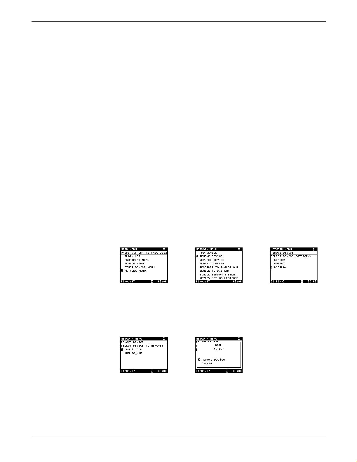
3.4.3.1 Removing a Device from the Network
Before physically removing a device from the system, this remove device
software procedure must be performed. This assures that all network
communications associated with the device are properly removed to avoid
miscommunication from other devices on the network. Proceed as follows:
1. Press the MENU key to access the Main Menu.
2. Use the up or down arrow key to move the pointer to NETWORK MENU
and press ENTER.
3. Select REMOVE DEVICE and press ENTER.
4. From the list of device categories, select the device type to be removed
and press ENTER.
Note: Press the Configure button on the device to be removed (press the ENTER key
on the AquaTrend Interface) or continue with Step 5 and 6 to make the device
selection via the AquaTrend Interface software.
5. Select the specific device to remove and press the ENTER key.
6. Press ENTER to remove the device or move the pointer to CANCEL to
end the operation without changes.
Page 28
Network Setup
51350-18 Initial Aquatrend Setup.fm
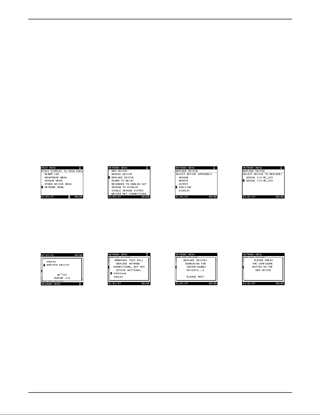
3.4.3.2 Replacing a Device on the Network
Before beginning the replace device procedure, the new device must be
physically attached (wired) to the network and powered. Refer to the
installation section in the device manual for information.
1. Press the MENU key to access the Main Menu.
2. Use the up or down arrow key to move the pointer to Network Menu and
press ENTER.
3. Select REPLACE DEVICE and press the ENTER key. A list of devices to
replace will appear.
4. Select the type of device to replace and press ENTER.
5. Select the device to replace (if more than one device is available for
replacement) and press ENTER. Or, press the configure button on the
device you want to replace (press the ENTER key on a remote AquaTrend
Interface). If only one device to replace is available, it will be selected
automatically.
Section 3
6. A pop-up box will appear showing the device to be replaced. If it is
correct, choose REPLACE DEVICE.
7. A warning pop-up box will appear. Select CONTINUE and press the
ENTER to continue with the replacement.
8. A search for available replacement devices will begin. If more than one is
found, press the configure button on the replacement device (press the
ENTER key on a remote AquaTrend Interface).
9. When the replace procedure is complete, a status screen appears. Press
the ENTER key to acknowledge and continue normal operations.
10. Now that the device has been replaced you must verify and/or replace all
device specific settings.
Page 29
51350-18 Initial Aquatrend Setup.fm Network Setup
 Loading...