


 Loading...
DOC023.53.90007
sc1000 controller
USER MANUAL
April 2008, Edition 1
© Hach Company, 2008. All rights reserved. Printed in the U.S.A. |
as/cw |

Table of Contents
Section 1 Specifications.................................................................................................................... |
5 |
||
Section 2 General Information......................................................................................................... |
9 |
||
2.1 |
Safety information ........................................................................................................................ |
9 |
|
2.1.1 |
Use of hazard information................................................................................................... |
9 |
|
2.1.2 |
Precautionary labels ......................................................................................................... |
10 |
|
2.2 |
General product information ...................................................................................................... |
10 |
|
2.3 |
Controller storage ...................................................................................................................... |
10 |
|
Section 3 Installation........................................................................................................................ |
11 |
||
3.1 |
Mechanical installation............................................................................................................... |
11 |
|
3.1.1 |
Controller dimensions ....................................................................................................... |
12 |
|
3.2 |
Mounting the controller .............................................................................................................. |
13 |
|
3.2.1 |
Wall mounting ................................................................................................................... |
13 |
|
3.2.2 |
Vertical or horizontal pipe mounting.................................................................................. |
14 |
|
3.2.3 |
Panel Mounting ................................................................................................................. |
14 |
|
3.2.4 |
Sun-shield ......................................................................................................................... |
14 |
|
3.3 |
Wiring safety information ........................................................................................................... |
14 |
|
3.3.1 |
Electrostatic discharge (ESD) considerations................................................................... |
15 |
|
3.4 |
Electrical installation .................................................................................................................. |
16 |
|
3.4.1 |
Installation in hard-wired applications ............................................................................... |
16 |
|
3.4.2 |
Installation using a power cord ......................................................................................... |
17 |
|
3.4.3 |
Wiring for AC power at the controller ................................................................................ |
20 |
|
3.4.4 |
Wiring for 24 VDC power at the controller ........................................................................ |
24 |
|
3.5 |
DIN rail expansion modules ....................................................................................................... |
26 |
|
3.6 |
Expansion cards ........................................................................................................................ |
27 |
|
3.6.1 |
Relay card connections..................................................................................................... |
28 |
|
3.6.2 |
Input card connections...................................................................................................... |
31 |
|
3.6.3 |
Output card connections ................................................................................................... |
33 |
|
3.6.4 |
Modbus card connections ................................................................................................. |
34 |
|
3.6.5 |
Profibus DP card connections........................................................................................... |
35 |
|
3.6.6 Remove/Replace an expansion card ................................................................................ |
37 |
||
3.7 |
Install an sc1000 network (sc1000 bus connection) .................................................................. |
37 |
|
3.7.1 |
sc1000 network connections............................................................................................. |
38 |
|
3.8 |
Connect probes to the sc1000 controller ................................................................................... |
43 |
|
3.8.1 |
Connect the probe data cable........................................................................................... |
43 |
|
3.8.2 |
Add probe connections ..................................................................................................... |
44 |
|
3.8.3 Connect AC powered sc probes ....................................................................................... |
44 |
||
3.9 |
Service port connection (LAN connection)................................................................................. |
44 |
|
3.10 GSM modem connection ......................................................................................................... |
45 |
||
3.10.1 |
Safety precautions .......................................................................................................... |
45 |
|
3.10.2 |
SIM card requirements.................................................................................................... |
46 |
|
3.10.3 |
Insert the SIM card into the display module.................................................................... |
47 |
|
3.10.4 |
Connect the external GSM antenna to the display module............................................. |
48 |
|
3.11 |
Storage card (SD card)............................................................................................................ |
49 |
|
3.11.1 |
Insert the storage card into the display module .............................................................. |
49 |
|
3.11.2 |
Prepare the storage card ................................................................................................ |
50 |
|
Section 4 System Start Up .............................................................................................................. |
51 |
||
Section 5 Standard Operations...................................................................................................... |
53 |
||
5.1 |
The display module.................................................................................................................... |
53 |
|
5.1.1 |
Attach the display module to the probe module................................................................ |
53 |
|
5.1.2 |
Tips for the use of the touch screen.................................................................................. |
54 |
|
5.1.3 |
The display modes............................................................................................................ |
54 |
|
1

Table of Contents
5.2 |
The measured value display ...................................................................................................... |
55 |
|
5.2.1 |
Daily and weekly trend lines.............................................................................................. |
56 |
|
5.2.2 |
Configure the measured value display .............................................................................. |
56 |
|
5.3 |
The Graph display ...................................................................................................................... |
56 |
|
5.4 |
The Main menu display .............................................................................................................. |
58 |
|
5.5 |
The alphanumeric keypad .......................................................................................................... |
59 |
|
5.6 |
Calibrate the touch screen ......................................................................................................... |
59 |
|
5.7 |
Specify the displayed language.................................................................................................. |
59 |
|
5.8 |
Set the time and date ................................................................................................................. |
60 |
|
5.9 |
Set up system security (passcode protection)............................................................................ |
60 |
|
5.9.1 |
Set the passcode............................................................................................................... |
60 |
|
5.10 Add and remove favorites ........................................................................................................ |
61 |
||
5.11 Add new components............................................................................................................... |
61 |
||
5.12 |
Configure the network modules (Profibus/Modbus cards) ....................................................... |
62 |
|
5.12.1 |
Configure the Profibus/Modbus card............................................................................... |
62 |
|
5.12.2 |
Error and status register.................................................................................................. |
64 |
|
5.12.3 |
Profibus/Modbus configuration example ......................................................................... |
66 |
|
5.13 Remote control ......................................................................................................................... |
67 |
||
5.13.1 Prepare the LAN connection ........................................................................................... |
67 |
||
5.13.2 Set up the LAN connection.............................................................................................. |
67 |
||
5.13.3 |
Set up the dial-up connection.......................................................................................... |
68 |
|
5.13.4 |
Access the sc1000 controller through a web browser..................................................... |
70 |
|
5.14 Log data ................................................................................................................................... |
71 |
||
5.14.1 |
Save log files to the storage card .................................................................................... |
71 |
|
5.14.2 |
Save log files through browser access............................................................................ |
71 |
|
5.14.3 |
Remove log files through browser access....................................................................... |
72 |
|
5.15 |
Formula editor for output and relay card .................................................................................. |
73 |
|
5.15.1 Add a formula .................................................................................................................. |
73 |
||
5.15.2 Add a formula with measurement values from other probes ........................................... |
74 |
||
5.15.3 |
Formula operations.......................................................................................................... |
74 |
|
Section 6 Advanced Operations .................................................................................................... |
77 |
6.1 Sensor status menu ................................................................................................................... |
77 |
6.2 Sensor setup menu .................................................................................................................... |
77 |
6.3 System setup menu.................................................................................................................... |
78 |
6.3.1 Output setup menu............................................................................................................ |
78 |
6.3.2 Current inputs menu.......................................................................................................... |
83 |
6.3.3 Relay menu ....................................................................................................................... |
87 |
6.3.3.1 General relay settings (available in all relay working modes)................................... |
87 |
6.3.3.2 Function set to ALARM working mode ..................................................................... |
88 |
6.3.3.3 Function set to FEEDER CONTROL working mode ................................................ |
90 |
6.3.3.4 Function set to 2 POINT CONTROL working mode ................................................. |
93 |
6.3.3.5 Function set to WARNING working mode ................................................................ |
97 |
6.3.3.6 Function set to PWM CONTROL/LINEAR working mode ........................................ |
99 |
6.3.3.7 Function set to PWM CONTROL/PID CONTROL working mode........................... |
102 |
6.3.3.8 Function set to FREQ. Control / Linear working mode ........................................... |
103 |
6.3.3.9 Function set to FREQ. Control/PID CONTROL mode............................................ |
105 |
6.3.3.10 Function set to TIMER working mode .................................................................. |
106 |
6.3.3.11 Function set to SYSTEM ERROR working mode................................................. |
108 |
6.3.4 Network Modules (Profibus, Modbus) ............................................................................. |
109 |
6.3.4.1 Profibus .................................................................................................................. |
109 |
6.3.4.2 Modbus................................................................................................................... |
111 |
6.3.5 GSM module.................................................................................................................... |
113 |
6.3.6 Device management........................................................................................................ |
115 |
2

|
|
|
Table of Contents |
|
|
|
|
|
6.3.7 |
Display settings............................................................................................................... |
115 |
|
6.3.8 |
Browser access............................................................................................................... |
116 |
|
6.3.9 |
Storage card ................................................................................................................... |
116 |
|
6.3.10 Security setup ............................................................................................................... |
117 |
|
6.4 |
Test/Maint Menu ...................................................................................................................... |
117 |
|
|
6.4.1 |
Bus status ....................................................................................................................... |
118 |
Section 7 Maintenance .................................................................................................................. |
119 |
||
7.1 |
General maintenance............................................................................................................... |
119 |
|
7.2 |
Fuse replacement .................................................................................................................... |
119 |
|
Section 8 Troubleshooting ........................................................................................................... |
121 |
||
8.1 |
General problems and GSM module errors ............................................................................. |
121 |
|
8.2 |
GSM Module errors.................................................................................................................. |
122 |
|
8.3 |
Error and warning messages ................................................................................................... |
122 |
|
|
8.3.1 Message type.................................................................................................................. |
122 |
|
|
8.3.2 Message format .............................................................................................................. |
123 |
|
|
8.3.3 |
Error and warning ID numbers........................................................................................ |
123 |
8.4 |
SMS service............................................................................................................................. |
124 |
|
|
8.4.1 |
Configure SMS destination ............................................................................................. |
124 |
|
8.4.2 SMS format ..................................................................................................................... |
124 |
|
8.5 |
Test the expansion cards in the Maintenance menu ............................................................... |
126 |
|
|
8.5.1 |
Test the output card ........................................................................................................ |
126 |
|
8.5.2 |
Test the input card .......................................................................................................... |
127 |
|
8.5.3 |
Test the relay card .......................................................................................................... |
128 |
Section 9 Replacement Parts and Accessories....................................................................... |
129 |
||
9.1 |
Expansion cards ...................................................................................................................... |
129 |
|
9.2 |
External DIN rail modules ........................................................................................................ |
129 |
|
9.3 |
Internal network components................................................................................................... |
129 |
|
9.4 |
Accessories.............................................................................................................................. |
129 |
|
9.5 |
Replacement parts................................................................................................................... |
130 |
|
9.6 |
Exploded view drawings .......................................................................................................... |
132 |
|
Section 10 Contact Information................................................................................................... |
137 |
||
Section 11 |
Certification ................................................................................................................. |
139 |
|
Appendix A DIN Rail Expansion Modules................................................................................. |
141 |
||
3

Table of Contents
4

Section 1 |
Specifications |
|
|
|
|
|
Specifications are subject to change without notice. |
|
|||
|
|
|
|
|
|
Display Module |
|
|
|
|
|
|
|
|
|
||
Component description |
|
Display module for menu-based operation |
|
||
|
|
|
|
||
Enclosure |
|
Plastic housing, enclosure rating IP65 |
|
||
|
|
|
|||
Screen display |
|
QVGA, 320 x 240 pixels, viewing area: 111,4 mm x 83,5 mm, 256 colors, touch |
|||
|
screen |
|
|
|
|
|
|
|
|
|
|
|
|
|
|||
Operating temperature |
|
–20 to 55 °C (–4 to 131 °F); 95 % relative humidity, non-condensing |
|||
|
|
|
|||
Storage temperature |
|
–20 to 70 °C (–4 to 158 °F); 95 % relative humidity, non-condensing |
|||
|
|
|
|
|
|
Weight |
|
Approximately 1.2 kg |
|
|
|
|
|
|
|
||
Dimensions |
|
200 × 230 × 50 mm (7.9 × 9 × 2 inches) |
|
||
|
|
|
|
|
|
|
|
GSM modem |
|
|
|
|
|
The sc1000 display module with integrated GSM/GPRS modem transmits data |
|||
|
|
SMS messages and GPRS services in GSM nets. |
|||
Optional expansions |
|
The sc1000 is offered with different GSM frequency bands: |
|||
|
MC55 EGSM900 |
GSM1800 |
GSM1900 |
|
|
|
|
|
|||
|
|
MC56 |
GSM1800 |
GSM1900 |
GSM850 |
|
|
MC55/56 features GPRS multislot class 10 and supports the GPRS coding |
|||
|
|
schemes CS-1, CS-2, CS-3 and CS-4. |
|
||
|
|
|
|
|
|
Probe Module |
|
|
|
|
|
|
|
|
|||
Component description |
|
Probe module for the connection of sc probes, optional expansions and power |
|||
|
supply |
|
|
|
|
|
|
|
|
|
|
|
|
|
|||
Enclosure |
|
Metal housing with corrosion-resistant surface finish, IP65 rating |
|||
|
|
|
|||
Power requirements |
|
100–240 V ± 10 VAC, 50 / 60 Hz, max. 2000 VA, Category II or 24 VDC |
|||
|
(18–30 VDC), max. 75 W |
|
|
||
|
|
|
|
||
|
|
|
|||
Probe inputs (optional)1 |
|
4, 6, or 8 probes. All parameters can be configured and combined as required. |
|||
Measuring range |
|
Dependent on probe. |
|
|
|
|
|
|
|||
Operating temperature |
|
–20 to 55 °C (–4 to 131 °F); 95 % relative humidity, non-condensing |
|||
|
|
|
|||
Storage temperature |
|
–20 to 70 °C (–4 to 158 °F); 95 % relative humidity, non-condensing |
|||
|
|
|
|
||
Weight |
|
Approximately 5 kg, depending on configuration |
|
||
|
|
|
|||
Optional expansions |
|
Analog Outputs, Analog/Digital Inputs, Relays, Digital fieldbusses |
|||
|
|
|
|||
Dimensions |
|
Without display module: 315 × 242 × 120 mm (12.4 × 10.1 × 4.8 inches) |
|||
|
|
|
|
|
|
|
With display module: 315 × 242 × 150 mm (12.4 × 10.1 × 6 inches) |
||||
|
|
||||
|
|
|
|||
Fuse ratings |
|
100–240 VAC: F1, F2: M 3,5 A (medium slow-blow); F3, F4: T 8 A; 100–240 V |
|||
|
|
|
|
|
|
|
24 VDC: 1 fuse, T 6,3 A; 24 VDC |
|
|
||
|
|
|
|
||
|
|
|
|||
|
|
Double-shielded control cable with 2 cores, 24 AWG, stranded, CU wire |
|||
sc1000 network cable |
|
Characteristics impedance at 1 KHz > 100 W, wire color: red and green. |
|||
|
Outer sheath of the cable is UV and water resistant |
||||
|
|
||||
|
|
External diameter of cable is 3.5–5 mm |
|
||
|
|
|
|
|
|
5

Specifications
Plug-in Expansion Cards
Component description |
Plug-in expansion cards for installation in the probe module |
|
|
|
|
Operating temperature |
–20 to 55 °C (–4 to 131 °F); 95% relative humidity, non-condensing |
|
|
|
|
Storage temperature |
–20 to 70 °C (–4 to 158 °F); 95% relative humidity, non-condensing |
|
|
|
|
Analog output card |
4 x analog current outputs (0–20 mA or 4–20 mA, max. 500 Ohm) |
|
Terminals max. 1.5 mm2 (AWG15) |
||
|
||
|
|
|
Analog/digital input card |
4 x analog/digital inputs (0–20 mA or 4–20 mA) Terminals max. 1.5 mm2 |
|
|
4 x change over contacts (SPDT) |
|
Internal relay card |
Maximum switching voltage: 250 VAC, 125 VDC |
|
Nominal Switching Current: 250 VAC, 5 A; 125 VAC, 5 A; 30 VDC, 5 A |
||
|
||
|
Terminals max. 1.5 mm2 (AWG15) |
|
|
|
|
Fieldbus interface card |
Modbus RS485 (YAB021), Modbus RS232 (YAB047) or Profibus DP (YAB020) |
|
|
|
|
DIN Rail Switch Cabinet Expansion Modules |
||
|
|
|
Function |
For installation in the switch cabinet. Any expansions required can be combined |
|
when a base module is available. |
||
|
||
|
|
|
Enclosure rating |
IP20 |
|
|
|
|
Power supply |
24 VDC (max. 30 V) from base module |
|
|
|
|
Operating temperature |
4 to 40 °C (39 to 104 °F); 95% relative humidity, non-condensing |
|
|
|
|
Storage temperature |
–20 to 70 °C (–4 to 158 °F); 95% relative humidity, non-condensing |
|
|
|
|
|
Supply of expansion modules with 24 VDC and connection to the sc1000 |
|
|
network |
|
|
Setting terminating resistor (with DIP switch) for the sc1000 network |
|
Base module (LZX915) |
Provision of connection for a display module (LXV402) for the configuration of |
|
|
the system |
|
|
Base module can supply a maximum of 2000 mA to the extension modules. |
|
|
|
|
|
Dimensions: 23 x 100 x 115 mm (1 x 4 x 4.5 in.) |
|
|
|
|
|
4 x normally closed into change over contacts (SPDT) |
|
|
Maximum switching voltage: 250 VAC, 125 VDC |
|
|
Maximum switching current: 250 VAC, 5 A; 125 VAC, 5 A; 30 VDC, 5 A |
|
|
Maximum switching power: 150 W |
|
Relay module (LZX920) |
Can be programmed for limit, status-monitoring or for various control functions, |
|
|
communication status indication by LED. |
|
|
Terminals max. 2.5 mm2 (AWG 11) |
|
|
Current consumption: <100 mA |
|
|
|
|
|
Dimensions: 45 x 100 x 115 mm (2 x 4 x 4.5 in.) |
|
|
|
|
|
2 analog current outputs (0–20 mA or 4–20 mA, max. 500 Ohm) |
|
Output module (LZX919) |
Terminals max. 2.5 mm2 (AWG 11) |
|
Current consumption: <150 mA |
||
|
||
|
|
|
|
Dimensions: 23 x 100 x 115 mm (1 x 4 x 4.5 in.) |
|
|
|
|
|
Analog/Digital inputs (can be programmed as 0–20 mA or 4–20 mA), INPUT or |
|
|
digital INPUT |
|
Input module (LZX921) |
Internal resistance: 180 Ohm |
|
Terminals max. 2.5 mm2 (AWG 11) |
||
|
||
|
Current consumption: <100 mA |
|
|
|
|
|
Dimensions: 23 x 100 x 115 mm (1 x 4 x 4.5 in.) |
|
|
|
|
6

Specifications
Certifications
|
sc1000 with system components |
|
- cTUVus to UL 61010-1 & CAN/CSA 22.2 No. 61010-1 |
North America |
sc1000 with GSM Module |
|
- FCC ID No. QIPMC56 |
|
- Industry Canada ID No. 267W-MC56 |
|
|
|
sc1000 with system components: |
|
- CE Conforms to LV-Directive 2006/95/EC, EMC-Directive 2004/108/EC |
Europe |
- TUV-GS to EN61010-1 |
|
sc1000 with GSM Module: |
|
- CETECOM ICT GmbH Registration No. M352023P-EO |
|
|
Warranty |
|
|
|
Warranty |
1 year |
|
|
1When installing additional probes, observe the maximum total power of the system. Only two 1720E Turbidity instruments can be used simultaneously on an sc1000 probe module.
Important Note: All modules and cards are developed according to DIN EN 61326 “Surge protection”.
7

Specifications
8
Section 2 General Information
The information in this manual has been carefully checked and is believed to be accurate. However, the manufacturer assumes no responsibility for any inaccuracies that may be contained in this manual. In no event will the manufacturer be liable for direct, indirect, special, incidental or consequential damages resulting from any defect or omission in this manual, even if advised of the possibility of such damages. In the interest of continued product development, the manufacturer reserves the right to make improvements in this manual and the products it describes at any time, without notice or obligation.
Revised editions are found on the manufacturer’s web site.
2.1 Safety information
Please read this entire manual before unpacking, setting up or operating this equipment. Pay attention to all danger, warning and caution statements. Failure to do so could result in serious injury to the operator or damage to the equipment.
Make sure that the protection provided by this equipment is not impaired, do not use or install this equipment in any manner other than that specified in this manual.
DANGER
The manufacturer products designed for outdoor use are provided with a high level of ingress protection against liquids and dust. If these products are connected to a mains electricity socket by means of a cable and plug rather than by fixed wiring, the level of ingress protection of the plug and socket connection against liquids and dust is considerably lower. It is the responsibility of the operator to protect the plug and socket connection in such a manner that the connection has an adequate level of ingress protection against liquids and dust and complies with the local safety regulations.
When the instrument is used outdoors, it should be connected only to a suitable socket with at least IP44 rating (protection against water sprayed from all directions).
2.1.1 Use of hazard information
DANGER
Indicates a potentially or imminently hazardous situation which, if not avoided, will result in death or serious injury.
WARNING
Indicates a potentially or imminently hazardous situation which, if not avoided, could result in death or serious injury.
CAUTION
Indicates a potentially hazardous situation that may result in minor or moderate injury.
Notice: Indicates a situation that is not related to personal injury.
Important Note: Indicates a situation which, if not avoided, may cause damage to the instrument. Information that requires special emphasis.
Note: Information that supplements points in the main text.
9

General Information
2.1.2 Precautionary labels
Read all labels and tags attached to the instrument. Personal injury or damage to the instrument could occur if not observed
This symbol, if noted on the instrument, references the instruction manual for operation and/or safety information.
This symbol, when noted on a product enclosure or barrier, indicates that a risk of electrical shock and/or electrocution exists.
This symbol, if noted on the product, indicates the need for protective eye wear.
This symbol, when noted on the product, identifies the location of the connection for Protective Earth (ground).
This symbol, when noted on the product, identifies the location of a fuse or current limiting device.
2.2 General product information
The sc1000 is a multi-parameter controller designed to function with any of the digital probe family. A stand-alone sc1000 controller must have one display module and one probe module. The probe module can be configured to accept up to 8 digital probes.
More probes can be connected by creating an sc1000 network. An sc1000 network must have one display module and two or more probe modules. Only one display module is allowed per network. Each probe module can be configured to accept up to 8 probes each.
Each probe module can also be configured with relays, analog outputs, analog or digital inputs, and digital fieldbus cards.
Note: An sc1000 network accepts a maximum of 32 devices (including internal expansion cards, external modules and probes).
2.3 Controller storage
When storing the sc1000 controller, make sure that all important data is saved. Remove power and disconnect all connections from the system. Remove the probe module from its mounting. Store the probe module and display module in a protective film or dry cloth in a dry place.
All configurations are stored in the I/O cards. After approximately two weeks the date and time information is lost. The user has to enter the date and time information the next time the controller is started.
10
Section 3 |
Installation |
DANGER
Electrocution hazard. Only qualified personnel should conduct the tasks described in this section of the manual.
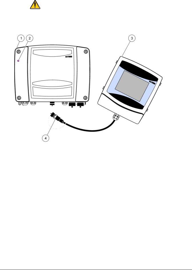
3.1 Mechanical installation
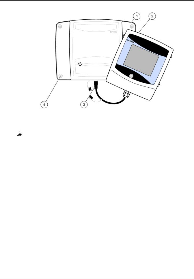
Figure 1 Probe module with display module
1 |
Probe module |
3 |
Display module |
|
|
|
|
2 |
LED indicator |
4 |
Connector, display module to probe module |
|
|
|
|
11
Installation
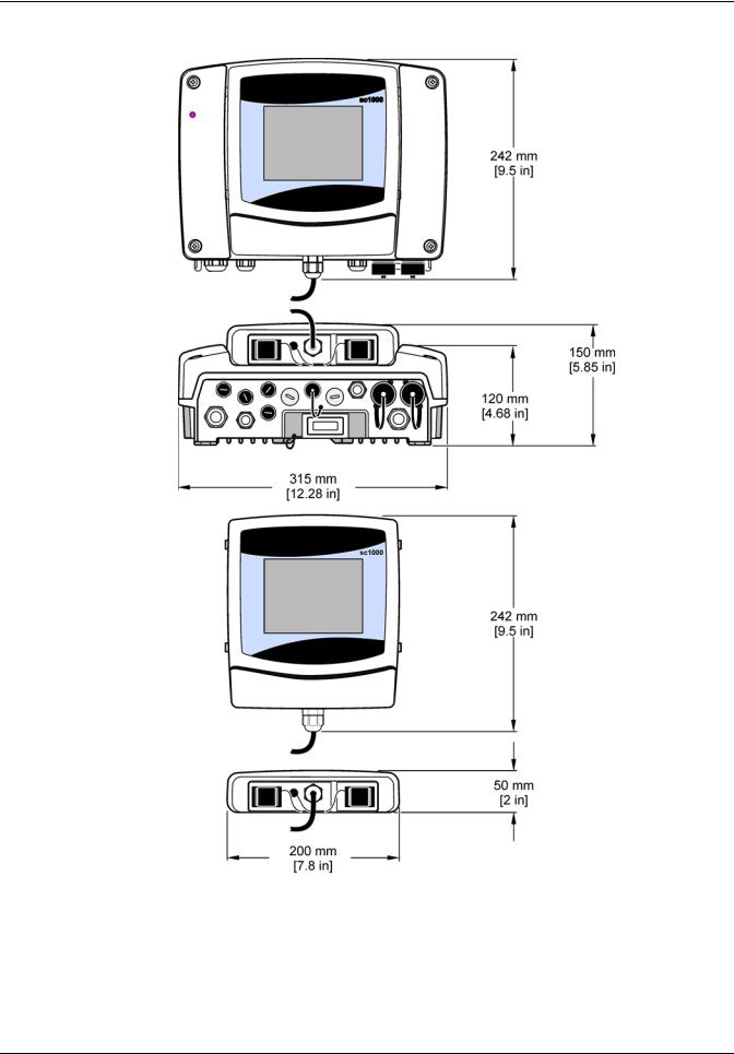
3.1.1 Controller dimensions
Figure 2 sc1000 controller dimensions
12
Installation
3.2 Mounting the controller
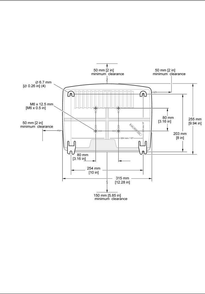
3.2.1 Wall mounting
Leave a minimum of 5 cm (2 in.) of space at the top and sides for cooling purposes and display module installation. Leave a minimum of 15 cm (6 in.) of space underneath for the cable connections. Refer to Figure 3 for proper wall mounting dimensions.
1.Install four bolts into the wall.
2.Hang the sc1000 controller over the bolts and attach the supplied washers and hand-tighten the two bottom bolts.
Figure 3 sc1000 controller mounting features
13
Installation
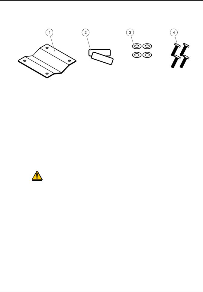
3.2.2 Vertical or horizontal pipe mounting
Refer to Figure 4 for mounting descriptions. For more information on pipe mounting refer to the instructions supplied with the mounting kit.
|
Figure 4 |
Pipe mounting hardware |
||
1 |
Bracket, pipe mount (LZY001) |
|
3 |
Flat washer (4x) (LZX948) |
|
|
|
|
|
2 |
Rubber pads (8x) (LZX948) |
|
4 |
Hexagon head screw (4x) M5 x 30 mm (LZX948) |
|
|
|
|
|
3.2.3 Panel Mounting
Refer to the instruction sheet supplied with the mounting hardware for installation instructions.
3.2.4 Sun-shield
The optional sun-shield is highly recommended for all outdoor installations. Refer to the instruction sheet supplied with the sun-shield for installation instructions.
3.3  Wiring safety information
DANGER
Electrocution hazard. Always disconnect power to the instrument when making electrical connections.
When making any wiring connections to the sc1000 Controller, the following warnings and notes must be adhered to, as well as any warnings and notes found throughout the individual installation sections. For more safety information refer to Safety information on page 9.
Remove the display module before performing any wiring tasks (Figure 5).
14
Installation
Figure 5 Remove display module and probe module cover
1 |
Probe module cover |
3 |
Connector, display module |
|
|
|
|
2 |
Display module |
4 |
Screw (4x) |
|
|
|
|
3.3.1  Electrostatic discharge (ESD) considerations
Important Note: To minimize hazards and ESD risks, maintenance procedures not requiring power to the analyzer should be performed with power removed.
Delicate internal electronic components can be damaged by static electricity, resulting in degraded instrument performance or eventual failure. The manufacturer recommends taking the following steps to prevent ESD damage to your instrument:
•Before touching any instrument electronic components (such as printed circuit cards and the components on them) discharge static electricity from your body. This can be accomplished by touching an earth-grounded metal surface such as the chassis of an instrument, or a metal conduit or pipe.
•To reduce static build-up, avoid excessive movement. Transport static-sensitive components in anti-static containers or packaging.
•To discharge static electricity from your body and keep it discharged, wear a wrist strap connected by a wire to earth ground.
•Handle all static-sensitive components in a static-safe area. If possible, use anti-static floor pads and work bench pads.
15

Installation
3.4 |
Electrical installation |
DANGER
Electrocution hazard. Only qualified personnel should conduct the installation tasks described in this section of the manual.
DANGER
Electrocution hazard. Always install a ground fault interrupt circuit (GFIC)/ residual current circuit breaker (rccb) with a maximum trigger current of 30 mA. If installed outside, provide overvoltage protection.
If installed outdoors, provide overvoltage protection between the power and the sc1000 controller. Make sure the data and power cables do not cause tripping and do not contain any sharp bends. Refer to Figure 7 for housing breakout information.
High-voltage wiring for the controller is conducted behind the high voltage barrier in the controller enclosure. The barrier must remain in place unless a qualified installation technician is installing wiring for power, alarms, or relays. See Figure 9 for barrier removal information.
The instrument can be wired for line power by hard-wiring in conduit or by wiring to a power cord if allowed by local electrical code. A local disconnect designed to meet local electrical code is required and must be identified for all types of installation.
Do not connect the electrical power supply to the AC power until the sc1000 controller has been fully wired, fused, and the high voltage barrier and probe module cover have been replaced.
3.4.1 Installation in hard-wired applications
In hard-wired electrical applications, the power and safety ground service drops for the instrument must be 18 to 12 AWG. A sealing-type strain relief must be used to maintain the IP65 environmental rating. See Figure 6 for strain relief and conduit opening sealing plug assembly. See Figure 13 for wiring information.
Note: There is no on/off switch to disconnect the probe module from AC Power.
16
Installation
3.4.2 Installation using a power cord
A sealing-type strain relief to maintain the IP65 environmental rating and a power cord less than 3 meters (10 feet) in length with three 18-gauge conductors (including a safety ground wire) can be used, see Section 9 on page 129. See Figure 6 for strain relief and conduit opening sealing plug assembly. See Figure 14 on wiring information.
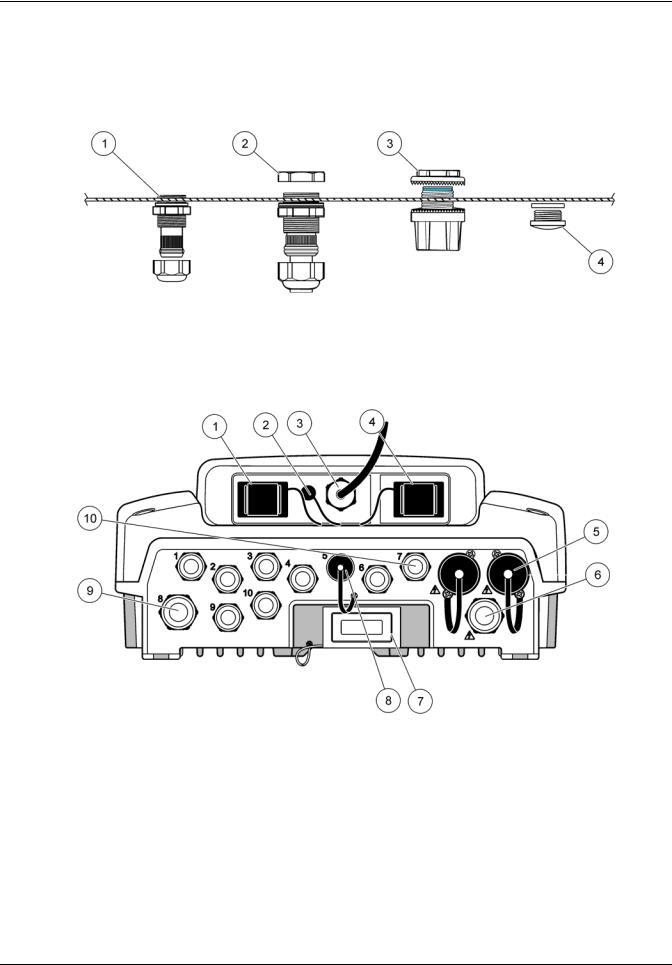
Figure 6 Using the optional strain relief and conduit plug
1 |
Strain relief, small |
3 |
Conduit |
|
|
|
|
2 |
Strain relief, large |
4 |
Plug, sealing |
|
|
|
|
Figure 7 Housing breakouts
1 |
Storage card slot |
6 |
AC power connection (PS1), strain relief M20 x 1.4 mm |
|
|
|
(4-8 mm cable diameter), conduit, different version of |
|
|
|
power cord (optional) |
|
|
|
|
2 |
GSM antenna connection (optional) |
7 |
Network interface |
|
|
|
|
3 |
Cable assembly for connection to probe module |
8 |
Cable assembly for connection to display module |
|
|
|
|
4 |
Service port |
9 |
Relay connection—2.19 mm for conduit or strain relief |
|
|
|
M20x1.5 with union mount (9–13.5 mm cable diameter) |
|
|
|
|
5 |
Power outlet for 100–240 VAC powered sc probes |
10 |
Configured as either sc probe connectors or |
|
|
|
strain-reliefs, M16 x 1.5 (5–6 mm cable diameter) |
17

Installation
|
|
Figure 8 Removing the probe module cover |
|
1 |
Ground screw |
|
3 Probe module cover |
|
|
|
|
2 |
Ground wire |
|
|
|
|
|
|
|
Figure 9 Removing high voltage barrier |
|
1 High voltage barrier |
|
2 Screw (6x) |
|
|
|
18
Installation
Figure 10 Wiring for power
1 |
AC power connections |
3 |
Ferrite will fit snugly in this area |
|
|
|
|
2 |
Earth Ground Connections |
4 |
Barrier should fit easily into position |
|
|
|
|
19
Installation
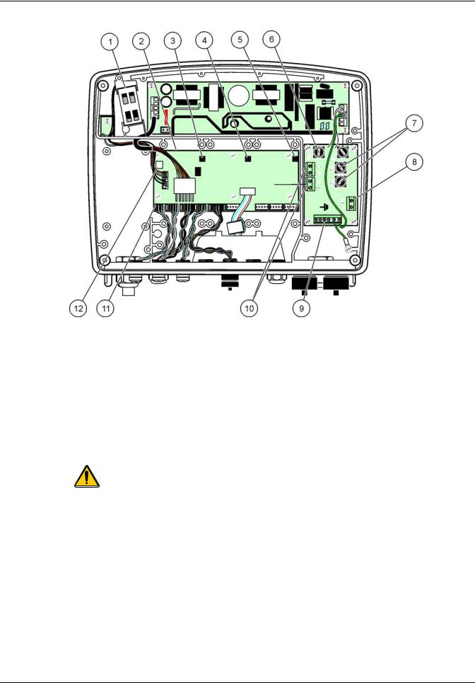
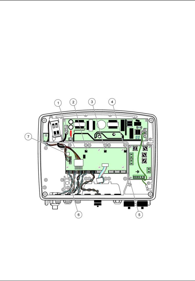
Figure 11 Inside the AC probe module
1 |
Fan |
7 |
Fuse (2x), F3 and F4: T 8A; 100–240 V, slow-blow |
|
|
|
|
2 |
Main circuit board |
8 |
AC power connections |
|
|
|
|
3 |
Connector for expansion slot |
9 |
Earth ground connection |
|
|
|
|
4 |
Connector for expansion slot |
10 |
Power outlet connection |
|
|
|
|
5 |
Connector for expansion slot |
11 |
Probe connections |
|
|
|
|
6 |
Fuse (2x), F1 and F2: M 3.5A, medium blow |
12 |
Relay card connection |
|
|
|
|
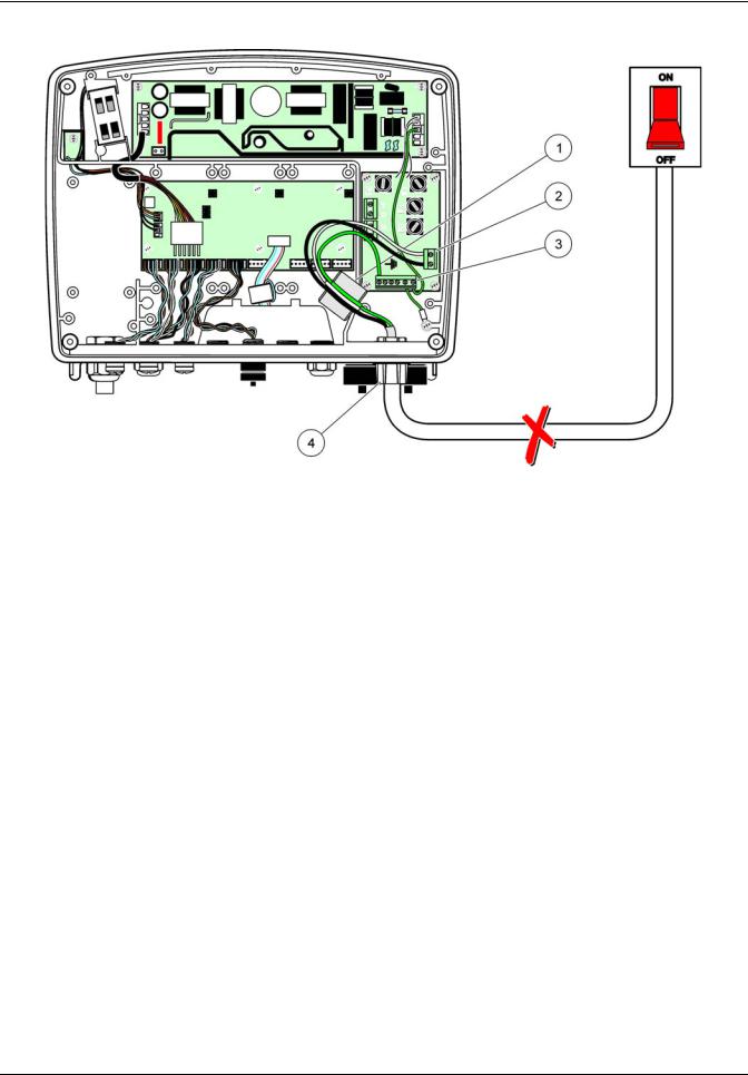
3.4.3 Wiring for AC power at the controller
DANGER
Electrocution hazard. Failure to connect to a good low impedance Protective Earth ground can result in both a shock hazard and poor performance against electro-magnetic interferences.
1.Obtain appropriate fittings with IP65 environmental rating.
2.Remove the display module from the probe module (Figure 5).
3.Remove the four screws securing the probe module front cover. Open the probe module and disconnect the chassis ground connection from the ground stud to the cover.
4.Remove the six screws from the high voltage barrier and remove the barrier.
5.Insert the wires through the PG1 opening and strain relief fitting or conduit hub. Tighten the strain relief if used, to secure the cord.
20
Installation
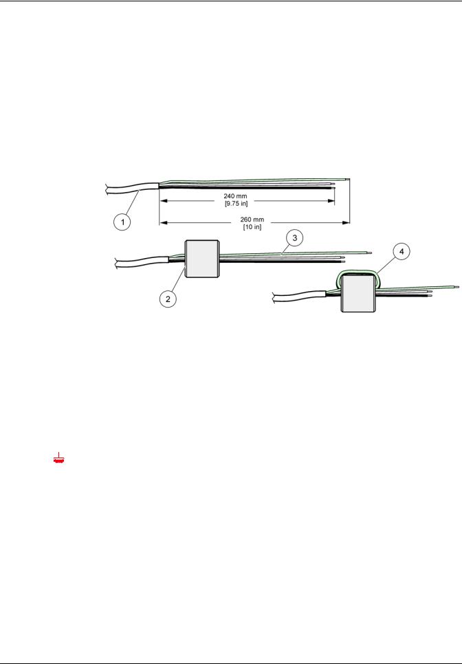
6.Strip the cable outer insulation 260 mm (10 in.) (Figure 12). Shorten all wires except the earth wire 20 mm (0.78 in.), so the earth cable is 20 mm (0.78 in.) longer than the other cables.
7.Feed the stripped power cable through the ferrite core twice (Figure 12) and wire into the terminal as shown in Table 1 and Figure 10. Tug gently after each insertion to make sure that the connection is secure.
8.Seal any unused openings in the controller box with conduit opening sealing plugs.
9.Install the high voltage barrier.
10.Connect the chassis ground connection to the ground stud of the probe module cover.
11.Install the probe module cover and screw into place.
Figure 12 Proper wire preparation and ferrite core wiring
1 |
Power cable wire preparation |
3 |
Power cable wires |
|
|
|
|
2 |
Ferrite core |
4 |
Power cables wrapped around ferrite core |
|
|
|
|
Table 1 AC power wiring information
Terminal number |
Terminal description |
Wire color code for North |
Wire color code for Europe |
||||
America |
|||||||
|
|
|
|
|
|
||
|
|
|
|
|
|
|
|
|
L |
Hot (L1) |
Black |
Brown |
|||
|
|
|
|
|
|
|
|
|
N |
Neutral (N) |
White |
Blue |
|||
|
|
|
|
|
|
|
|
|
|
|
|
Protective Earth (PE) |
Green |
Green w/yellow tracer |
|
|
|
|
|
||||
|
|
|
|
||||
|
|
|
|
|
|
|
|
21
Installation
Figure 13 Hard-wired installation
1 |
Ferrite core (Electromagnetic interference device) |
3 |
Earth ground connection |
|
|
|
|
2 |
AC power connections (optional, LZX970) |
4 |
Conduit hub, strain relief |
|
|
|
|
22
Installation
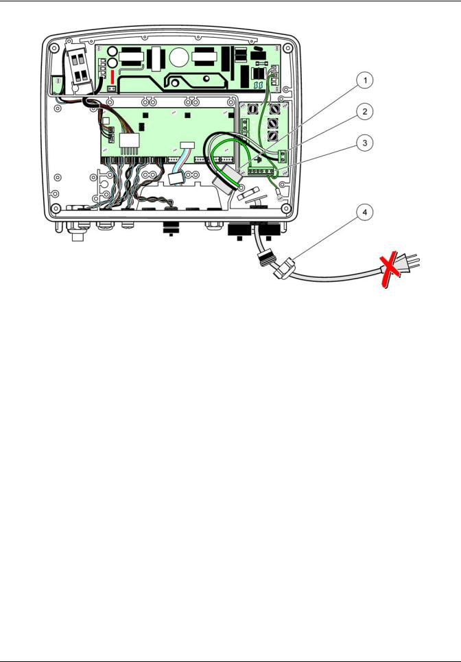
Figure 14 Installation with power cord
1 |
Ferrite core (Electromagnetic Interference Device) |
3 |
Earth ground connection |
|
|
|
|
2 |
AC power connections |
4 |
Strain relief |
|
|
|
|
23
Installation
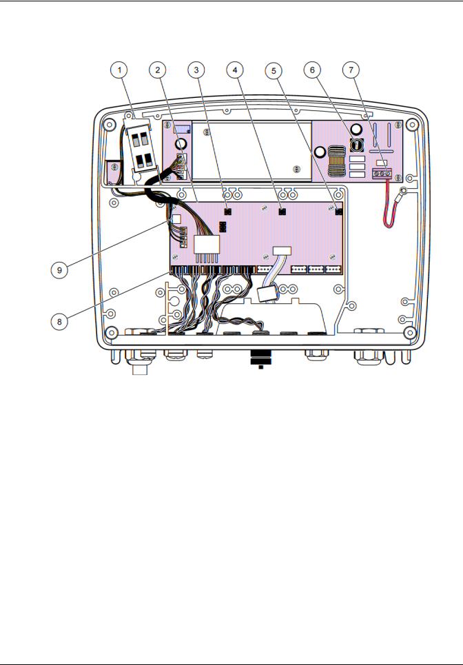
3.4.4 Wiring for 24 VDC power at the controller
Important Note: The AC power outlets cannot be used with the 24 VDC power supply.
Figure 15 Inside the 24 VDC probe module
1 |
Fan |
6 |
Fuse, T 6.3A, slow-blow |
|
|
|
|
2 |
Main circuit board |
7 |
24 VDC power connections |
|
|
|
|
3 |
Connector for expansion slot |
8 |
Probe connections |
|
|
|
|
4 |
Connector for expansion slot |
9 |
Relay card connection |
|
|
|
|
5 |
Connector for expansion slot |
|
|
|
|
|
|
24
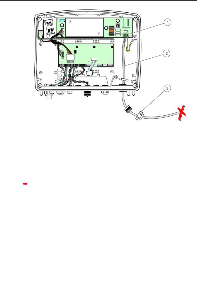
Installation
|
|
Figure 16 Wiring for 24 VDC power |
|
1 |
24 VDC power terminal block |
|
3 Strain relief |
|
|
|
|
2 |
Cable |
|
|
|
|
|
|
Table 2 DC power wiring information
Terminal number |
Terminal description |
Wire color code for North |
Wire color code for Europe |
||||
America |
|||||||
|
|
|
|
|
|
||
|
|
|
|
|
|
|
|
+ |
|
+24 VDC |
Red |
Brown |
|||
|
|
|
|
|
|
|
|
- |
|
24 VDC Return |
Black |
Blue |
|||
|
|
|
|
|
|
|
|
|
|
|
|
Protective Earth (PE) |
Green |
Green w/yellow tracer |
|
|
|
|
|
||||
|
|
|
|
|
|
|
|
25

Installation
3.5 DIN rail expansion modules
CAUTION
The expansion modules for control cabinet installation use the 24 VDC power supply in the control cabinet. Make sure that the correct power supply is provided. Install a residual current circuit breaker. The modules have an environmental rating of IP20 and must always be mounted in an enclosure suitably rated for power and environment.
The sc1000 controller can be expanded with DIN rail expansion modules. The following DIN rail module options can be installed:
•Base module (for connecting power, sc1000 network and display module)–The base module is required for the installation of expansion modules on the control cabinet.
•Relay card with 4 relays
•mA output card with 2 outputs
•mA input card with 2 inputs (analog or digital)–One base module can provide up to 2000 mA of power to the other modules connected to it on the DIN rail.
The total number of modules that can be connected together is limited by the power supply from the base module. Up to 13 communication modules can be attached to each base module. When more than 13 communication modules are needed, a second base module must be connected through the sc1000 network.
Refer to Appendix A on page 141 for more information about the DIN rail expansion modules.
26
Installation
3.6 Expansion cards
The sc1000 controller can be expanded with internal plug-in expansion cards. Each expansion component can be identified with its serial number on the sc1000 network and programmed as required. The serial number is located on the card.
It may be necessary to remove an existing expansion card, if the expansion card is blocking access to certain connectors. Refer to section 3.6.6 on page 37 for more information.
When an instrument is ordered, it comes pre-installed with the appropriate plug-in expansion cards. The following options can be connected:
•Relay card with 4 relays
•Digital field-bus cards (Modbus (RS485), Modbus (RS232), Profibus DP)
•mA output card with 4 outputs
•mA input card with 4 inputs (analog or digital)
•sc-probe connectors
Figure 17 Expansion card main circuit board connections
1 |
Main circuit card |
5 |
Mounting holes, input cards (4 each) |
|
|
|
|
2 |
Connector for expansion slot #2 |
6 |
sc probe connections |
|
|
|
|
3 |
Connector for expansion slot #3 |
7 |
Relay card connection |
|
|
|
|
4 |
Connector for expansion slot #4 |
|
|
|
|
|
|
27
Installation
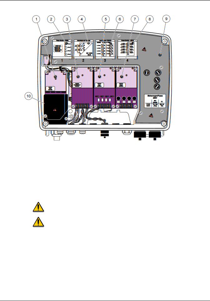
Figure 18 Expansion card ports
1 |
Relay card |
6 |
mA output or input wiring information |
|
|
|
|
2 |
Relay wiring information |
7 |
mA output or input card |
|
|
|
|
3 |
Field-bus or mA output or input card |
8 |
mA output or input wiring information |
|
|
|
|
4 |
Field-bus or mA output or input card wiring information |
9 |
Main high voltage barrier |
|
|
|
|
5 |
mA output or input card |
10 |
Relay voltage barrier |
|
|
|
|
3.6.1 Relay card connections
DANGER
Electrocution hazard. Relays must either be wired as low or high voltage.
DANGER
Fire hazard: Relay loads must be resistive. User must externally limit current to the relays to 5 Amps by use of a fuse or breaker.
The relay connector accepts 18–12 AWG wire (as determined by load application). Wire gauge less than 18 AWG is not recommended.
If the instrument is equipped with the relay card option, the instrument will include 4 relays, each with one change over contact. In this configuration, steps 3, 4 and 6 in To make a relay card connection are not applicable.
The relays can switch maximum 250 VAC, 5A. Each relay can be configured for different applications.
28
Loading...