


Service Document
Exchange Set
YACHT BOY 80 WR5408 PLL
Service |
Es gelten die Vorschriften und Sicherheitshinweise |
|
S gemäß dem Service Manual "Sicherheit", Material- |
||
Manual |
nummer 720108000001, sowie zusätzlich die even- |
|
Sicherheit |
tuell abweichenden, landesspezifischen Vorschrif- |
|
ten! |
||
Safety |
||
|
||
|
The regulations and safety instructions shall be |
|
Materialnr./Part No. |
S valid as provided by the "Safety" Service Manual, |
|
720108000001 |
part number 720108000001, as well as the |
|
respective national deviations. |
||
|
Dieses Service Dokument ist nur in Datenform verfügbar This Service Document is only available as data
Änderungen vorbehalten/Subject to alteration
Made by GRUNDIG in Germany • HS-41 0404 http://www.grundig.com
ALIGNMENT INSTRUCTIONS
(1)ALIGNMENT FOR AM IF
a.Required Instruments
AM IF Sweep Generator with Scope
b.Alignment Procedure
Mode |
Adjustment |
|
Procedure |
|
|
|
|
(1) |
Turn on the radio. |
|
|
|
(2) |
Connect the input of the AM IF sweep generation in series with a resister of 1.2K |
AM |
T2 |
|
|
Ohm to the test point TP2 and TP7. |
|
(3) |
Connect the RF output of the AM IF sweep generation in series with a resister of |
||
|
|
|
||
|
|
|
|
2.2K ohm to another test point TP3. |
(4)Adjust T2 to have a max. output and best center marker frequency to 450kHz.
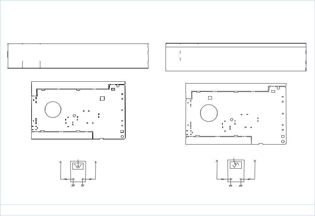
c.Instrument Connection
T2
(2)ALIGNMENT FOR FM IF
a.Required Instruments
FM IF Sweep Generator with Scope
b.Alignment Procedure
Mode |
Adjustment |
|
Procedure |
|
|
(1) |
Turn on the radio. |
|
|
(2) |
Connect the input of the FM IF sweep generation in series with a resister of 1.2k |
|
|
|
Ohm to the test point TP4 and TP7. |
FM |
T1 |
(3) Connect the RF output of the FM IF sweep generation in series with a resister of |
|
|
|
|
2.2k ohm to another test point TP5. |
|
|
(4) |
Adjust T1 have a max. output and best symmetrical S curve with respect to the |
|
|
|
Center marker frequency of 10.7MHz. |
c. Instrument Connection |
|
||
T1
|
450KHz Marker |
|
|
Test Point |
IN |
RF |
Test Point |
TP2 |
OUT |
TP3 |
|
|
|
||
|
1.2K |
2.2K |
|
|
FM IF Sweep Generator |
|
|
|
10.7MHz Marker |
|
|
Test Point |
IN |
RF |
Test Point |
TP4 |
OUT |
TP5 |
|
|
|
||
|
1.2K |
2.2K |
|
|
FM IF Sweep Generator |
|
|
YACHT BOY 80
(3) ALIGNMENT FOR FM VOLTAGE TUNING RANGE |
(4) ALIGNMENT FOR AM VOLTAGE TUNING RANGE |
|
|
a. Required Instruments |
a. Required Instruments |
|
|
DVM |
DVM |
|
|
b. Alignment Procedure |
b. Alignment Procedure |
Mode Adjustment |
|
|
Procedure |
|
Mode |
Adjustment |
|
|
Procedure |
||
|
|
(1) Set the power switch to ON. |
|
|
|
|
(1) Set the power switch to ON. |
||||
|
|
(2) |
Set |
“ 108 MHz”. |
|
|
T10 |
(2) |
Set |
“ 520 kHz”. |
|
|
L2 |
(3) |
Connect at to the test point TP6 and TP7. |
|
|
VC4 |
|
(3) |
Connect at to the test point TP6 and TP7. |
||
|
|
(4) |
Adjust L2 for show on 8.5V. |
|
|
|
(4) |
Adjust T10 for show on 1.10V. |
|||
|
|
|
|
|
|
||||||
|
|
(5) |
Set “87.5MHz” and check on DVM between 2.2V – 2.7V. |
|
|
|
|
(5) |
Set “1710 kHz” and adjust VC4 for DVM show on 8.5V. |
||
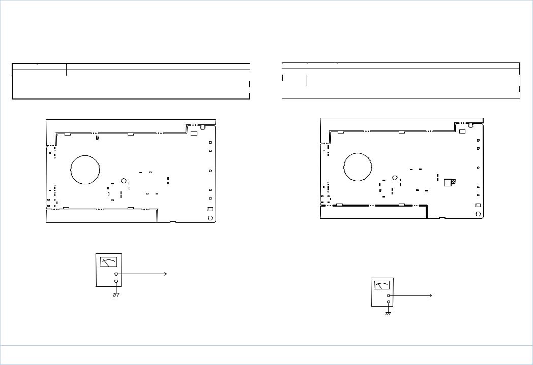
c. Instrument Connection |
|
|
|
c. Instrument Connection |
|
|
|||||
L2
T10
 VC4
VC4
DVM
Test Point TP6
DVM
Test Point TP6
YACHT BOY 80

(5)ALIGNMENT FOR LW VOLTAGE TUNING RANGE
a.Required Instruments DVM
b.Alignment Procedure
Mode Adjustment |
|
Procedure |
|
|
|
(1) Set the power switch to ON. |
|
|
T11 |
(2) |
Set “ 153 kHz”. |
|
(3) |
Connect at to the test point TP6 and TP7. |
|
|
VC5 |
||
|
(4) |
Adjust T11 for show on 1.20V. |
|
|
|
||
|
|
(5) |
Set “279 kHz” and adjust VC5 for DVM show on 5.00. |
c. Instrument Connection |
|
||
T11 |
VC5 |
DVM
Test Point TP6
(6)ALIGNMENT FOR FM SENSITIVITY
a.Required Instruments FM Signal Generator SSVM
b.Alignment Procedure
Mode |
Adjustment |
|
Procedure |
|
|
(1) Set the power switch to ON. |
|
|
|
(2) |
Connect a SSVM to the test point TP8 and TP9. |
|
|
(3) |
Connect the output of the FM signal generator to the test point TP5 and TP7. |
|
L1 |
(4) |
Set FM 90 MHz. |
|
VC1 |
(5) Adjust L1 to have a max. Audio output. |
|
|
|
(6) |
Set FM 106 MHz. |
|
|
(7) |
Adjust VC1 to have a max. Audio output. |
|
|
(8) |
Repeat steps 4-7 until best sensitivity on these two frequency is formed. |
c. Instrument Connection |
|
||
L1
VC1
FM Signal Generator |
SSVM |
Test |
Test Point TP8 |
Point TP5 |
YACHT BOY 80

(7)ALIGNMENT FOR AM SENSITIVITY
a.Required Instruments AM Signal Generator SSVM
b.Alignment Procedure
Mode Adjustment |
|
Procedure |
|
|
|
(1) Set the power switch to ON. |
|
|
|
(2) |
Connect a SSVM to the test point TP8 and TP9. |
|
|
(3) |
Connect the output of the FM signal generator to the test point TP8 and TP9. |
|
L19A |
(4) Set AM 600 kHz. |
|
|
VC2 |
(5) Adjust L19A to have a max. Audio output. |
|
|
|
(6) |
Set AM 1400 kHz. |
(7)Adjust VC2 to have a max. Audio output.
(8)Repeat steps 4-7 until best sensitivity on these two frequency is formed.
c.Instrument Connection
L19 |
A |
|
VC2
(8)ALIGNMENT FOR LW SENSITIVITY
a.Required Instruments AM Signal Generator SSVM
b.Alignment Procedure
Mode |
Adjustment |
|
Procedure |
|
|
(1) Set the power switch to ON. |
|
|
|
(2) |
Connect a SSVM to the test point TP8 and TP9. |
|
|
(3) |
Connect the output of the AM signal generator to a standard loop antenna. |
|
L19B |
(4) Set LW 162 kHz. |
|
|
VC3 |
(5) Adjust L19B to have a max. Audio output. |
|
|
|
(6) |
Set LW 270 kHz. |
|
|
(7) |
Adjust VC3 to have a max. Audio output. |
|
|
(8) |
Repeat steps 4-7 until best sensitivity on these two frequencies is formed. |
c. Instrument Connection |
|
B |
L19 |
|
VC3 |
AM Signal Generator |
|
|
AM Signal Generator |
|
|
|
|
|
|
SSVM |
|
|
|
|
|
60 cm |
|
|
60 cm |
|
|
|
|
Test Point TP8 |
|
|
|
Loop |
Antenna |
The radio is located |
Loop |
Antenna |
The radio is located |
|
perpendicularly to |
perpendicularly to |
|||||
|
|
|
|
|||
|
|
the Loop Antenna |
|
|
the Loop Antenna |
SSVM
Test Point TP8
YACHT BOY 80

(9)ALIGNMENT FOR SW 2 ND LOCAL OSC
a.Required Instruments
Frequency counter with higher impedunce probe
b.Alignment Procedure
Mode |
Adjustment |
|
Procedure |
|
|
|
(1) |
Turn the radio ON. |
|
AM |
T8 |
(2) |
Turn the frequency for away from any station to avoid interference. |
|
(3) |
Connect the test probes of frequency counter to TP10 and TP7. |
|||
|
|
|||
|
|
(4) |
Adjust T8 to have a reading of 20.9898 – 20.9902 MHz. |
|
Coution : a loading effect could emerge in the circuit if inserted with a lower impedance probe of frequency |
||||
|
Counter. |
|
|
|
c. Instrument Connection |
|
|||
T8
(10)ALIGNMENT FOR SW SENSITIVITY
a.Required Instruments AM Signal Generator SSVM
b.Alignment Procedure
Mode Adjustment
T6
T7
T9
|
Procedure |
(1) |
Turn on the radio. |
(2) |
Tune the radio band frequency to 15.100 MHz. |
(3) |
Feed a signal with modulation from the AM signal generator output to tese point |
|
TP5 and connect a SSVM to the speaker (TP8). |
(4) |
Tune the generator frequency to exactly the same as that of the radio frequency |
|
Displayed. |
(5) |
Adjust T6, T7 and T9. |
(6) |
Remove steps (5) until test sensitivity. |
c. Instrument Connection
A
T6 |
T7 |
T9 |
|
Freq. Counter
Test Point
TP10
AM Signal Generator |
SSVM |
Test Point TP5 |
Test Point TP8 |
|
YACHT BOY 80
 Loading...