


STR-642
STR 641
STR 641 EURO
STR 642
STR 642 EURO
Service Manual
SAT
Zusätzlich erforderliche
Unterlagen für den Komplettservice
Additionally required
Service Manuals for the Complete Service
Document supplémentaire nécessaire pour
la maintenance:
Ergänzung
Supplement
Supplément
Service
Manual
Service
Manual
Service
Manual
Btx * 32700 #
Sachnummer
Part Number
Ref. N° 72010-020.31
Änderungen vorbehalten
Subject to alteration
Sous réserve de modifications
Printed in Germany
VK22 0897
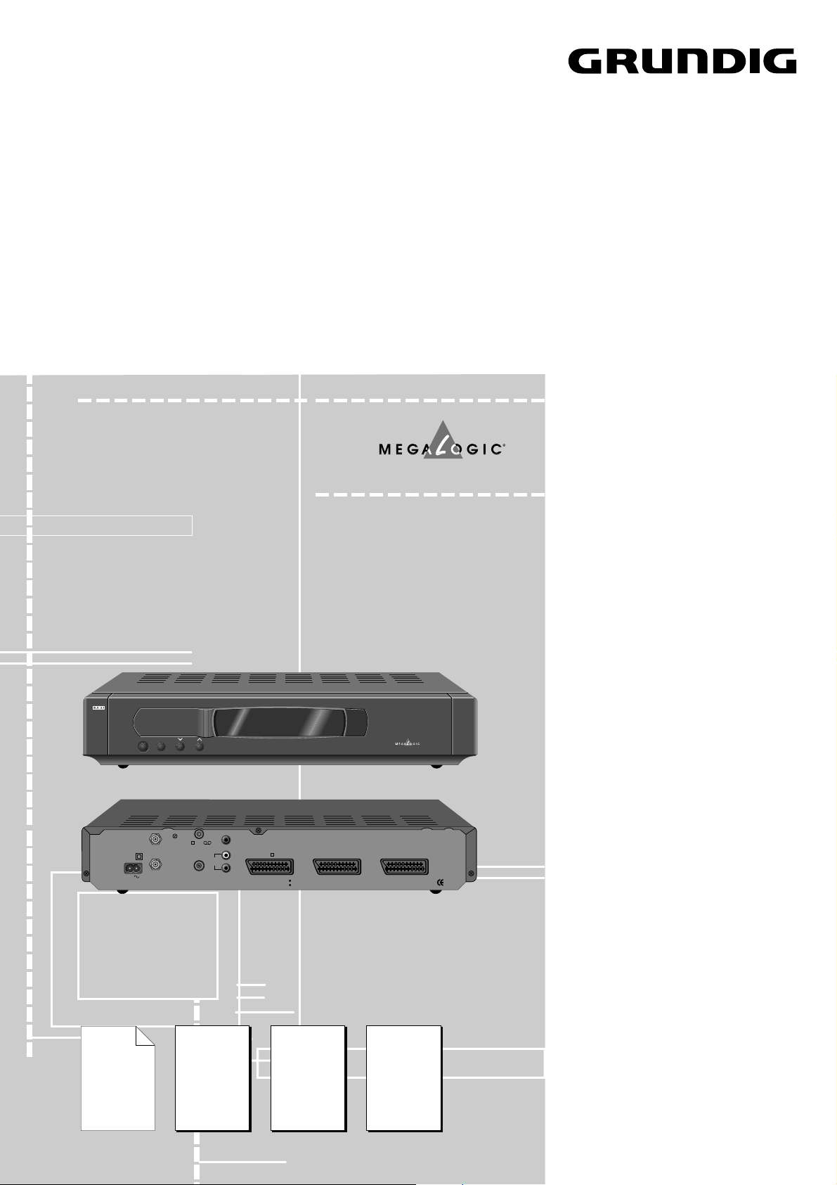
STR 642
À
F
1
8
CH. ADJ.
AERIAL
MADE IN U.K.
AUX1
HAZARD-LIVE PARTS
DO NOT REMOVE COVERS
R
L
AUDIO
MEGALOGIC SAT
OUT
40W MAX.
50 Hz
230V
LNC
13/18V
400mA DC
TV /VCR
INPUT
MAINS
TV
AUX2
1
2
STR 631
STR 632
Sach-Nr./Part No./
Ref. N°
72010-020.30
Sicherheit
Safety
Sach-Nr./Part No./
Ref. N°
72010-800.00
1
Sach-Nr./Part No./
Ref. N°
72010-020.31
STR 631 F
STR 632 F
Sach-Nr./Part No./
Ref. N°
72010-020.40

Allgemeiner Teil / General Section / Partie générale STR 641 …, STR 642 …
1 - 2 GRUNDIG Service
Modulübersicht / Module List / Composition des appareillles
GB
Table of Contents
Page
Technical Data ............................................ 2
Module List.................................................. 2
Layouts of the PCBs ................................... 3
Circuit Diagram Power Supply .................... 9
Circuit Diagram Signal Section ................. 11
Spare Parts List ........................................ 15
Introduction
For these TV sets the Service Manual STR 631 /
632 is applicable.
This Manual describes the differences and the
additionally fitted modules of the TV receivers.
The individual modules and the relevant part
numbers are listed in the table on page 2.
Basic instructions for servicing are given in the:
– Safety Instructions (Part No. 72010-800.00)
– Service Manual STR 631 / 632 (Part No.
72010-020.30)
D
Inhaltsverzeichnis
Seite
Technische Daten ....................................... 2
Modulübersicht............................................ 2
Chassisplatte PCBs .................................... 3
Schaltplan Netzteil ...................................... 9
Schaltplan Signalteil.................................. 11
Ersatzteilliste............................................. 15
Einführung
Für diese Geräte gilt das Service Manual
STR 631 / 632.
Diese Ergänzung dokumentiert die Unterschie-
de bzw. zusätzlichen Bestückungen der Gerä-
te.
Die Bausteinbestückung und die Sachnummern
der einzelnen Bausteine entnehmen Sie bitte
der Tabelle auf Seite 2.
Grundlage für den Service sind:
– Sicherheitsvorschriften (Sach-Nr. 72010-
800.00)
– Service Manual STR 631 / 632 (Sach-Nr.
72010-020.30)
F
Sommaire
Page
Caractéristiques techniquees...................... 2
Composition des appareillles ...................... 2
Circuits imprimés du C.I. Principal .................. 3
Schéma du C.I. Alimentation ...................... 9
Schéma du l'étage de traitement du signal .... 11
Liste de piéces détachées ........................ 16
Introduction
Pour ces téléviseurs le Service Manual
STR 631 / 632 EURO est valable.
Ce supplément contient les différences ainsi
que les équipements complémentaires des
appareils.
La liste des modules et des numéros de réference
sont indiqués sur le tableau de la page 2.
Les documents de base pour la maintenance sont:
– Prescriptions de Sécurité (Réf. N° 72010-
800.00)
– Service Manual STR 631 / 632 EURO
(Réf. N° 72010-020.40)
Technische Daten
Programmspeicherplätze ........ 300 TV/Radio
Eingangsfrequenzbereich .... 950…2150MHz
SAT-ZF-Eingang STR 641......................... 1
SAT-ZF-Eingang STR 642......................... 2
ZF-Bandbreite ....................................27MHz
LNB-Spannung ........... 13/18V, max. 400mA
DiSEqC ...................................... DiSEqC 1.0
LNB-Schaltsignal ................................ 22kHz
LNB-Anpassung
........................4 auswählbare LO-Frequenzen
LNB-Eigen-Oszillator ........9,0…11,99 variabel
Ton-Frequenzbereich............. 5,0…9,99MHz
Stereo ................................. Panda Wegener
Ton-Bandbreite .............. 50/100/150/200kHz
Ton-Deemphasis umschaltbar .......... 75µs/J17
Videohub...........................................variabel
Videopolarität ......................... positiv/negativ
Anzeige STR 641.................... 3-stellige LED
Anzeige STR 642................................... VFD
OSD-Menü .................................... D/GB/E/P
Scartbuchsen .................... TV, VCR, Decoder
Modulator ................................ Kanal 21…69
Netzspannung ............................. 220…240V
Regelbereich............................... 185…265V
Netzfrequenz..................................50 / 60Hz
Fernbedienung...........................TP 820 SAT
Keyboard......................................... 4 Tasten
Abmessungen (BxHxT) .......... 400x70x235 mm
Gewicht ..............................................ca. 2kg
Leistungsaufnahme mit LNC............ ca. 22W
Leistungsaufnahme in Standby........ ca 5,5W
Technical Data
Programme memory locations 300 TV/Radio
Input frequency range ..........950…2150MHz
SAT IF-input STR 641.................................1
SAT IF-input STR 642.................................2
IF bandwidth ..................................... 27MHz
LNB power .................. 13/18V, max. 400mA
DiSEqC ...................................... DiSEqC 1.0
LNB switching signal...........................22kHz
LNB-Adaption
.......................... 4 variabel LO-Adjustments
LNB local oscillator ...........9.0…11.99 variable
Sound frequency range..........5.0…9.99MHz
Stereo .................................Panda Wegener
Audio bandwidth ........... 50/100/150/200kHz
Sound de-emphasis, switchable ........ 75µs/J17
Video deviation ................................ variable
Video polarity ..................... positive/negative
Display STR 641 ........................ 3-digit LED
Display STR 642 ...................................VFD
OSD menu .................................... D/GB/E/P
Scart sockets .................. TV, VCR, Decoder
Modulator ............................ channel 21…69
Mains supply ...............................220…240V
Control range .............................. 185…265V
Mains frequency............................ 50 / 60Hz
Remote control handset............ TP 820 SAT
Keyboard............................................ 4 keys
Dimensions (WxHxD)......... 400x70x235 mm
Weight............................................... ca. 2kg
Power consumption with LNC..........ca. 22W
Power consumption in standby .......ca. 5.5W
Caractéristiques techniques
Positions de progr. mémor...... 300 TV/Radio
Niveau de fréqu. de réception ... 950…2150MHz
Entrée FI SAT STR 641 .............................. 1
Entrées FI SAT STR 642 ............................ 2
Largeur de bande FI ..........................27MHz
LNB-de puissance....... 13/18V, max. 400mA
DiSEqC ...................................... DiSEqC 1.0
Signal de commutation LNB ............... 22kHz
Adaption LNB
.................... 4 LO frequences à selectionner
Local oscillateur LNB .......... 9,0…11,99 variable
Fréquence porteuse audio ......... 5,0…9,99MHz
Stereo ................................. Panda Wegener
Bande passante audio...... 50/100/150/200kHz
Désaccentuation audio, commut. ...... 75µs/J17
Exursion video ..................................variable
Polarité video ..................... positive/negative
Afficheur STR 641....................... 3-digit LED
Afficheur STR 642.................................. VFD
Menu OSD .................................... D/GB/E/P
Embases Scart.............. TV, VCR, Decodeur
Modulateur .............................. Canal 21…69
Tension d'alimentation ................ 220…240V
Plage de réglage......................... 185…265V
Fréquence du réseau..................... 50 / 60Hz
Télécommande ..........................TP 820 SAT
Keyboard....................................... 4 touches
Dimensions (LxHxP) ............. 400x70x235 mm
Poids ............................................... env. 2kg
Puissance avec LNC...................... env. 22W
Puissance en veille ....................... env. 5,5W
Bestell-Nr.
Order No.
No. de Commande
Modulator
Modulateur
Tuner
Fluoreszenz-Anzeige
Fluorescence Display
Indication de Flouresc.
LED-Platte kpl.
LED Board cpl.
Principal de LED cpl.
Fernbedienung
Remote Control
Télécommande
TP 820 SAT
STR 641 G.AC 6251
75990-900.31 75990-900.54 – 75990-900.22 29642-061.03
STR 641 EURO G.AD 5151
75990-900.31 75990-900.54 – 75990-900.22 29642-061.03
STR 642 G.AD 4051
75990-900.43 75990-900.42 75990-900.41 – 29642-061.03
STR 642 EURO G.AD 5251
75990-900.43 75990-900.42 75990-900.41 – 29642-061.03
STR 641 …, STR 642 … Platinenabbildungen und Schaltpläne / Layout of the PCBs and Circuit Diagrams / Circuits imprimés et schemas électriques
GRUNDIG Service 3
Pos.-Nr./ Koordinaten/
Pos. No./ Coordinates
Pos. N° Coordonnées
XY
C102 58 67
C104 140 34
C105 71 70
C200 23 35
C201 16 97
C202 17 164
C203 16 179
C205 14 189
C208 31 161
C209 23 129
C210 43 125
C221 69 170
C223 79 160
C225 69 154
C226 90 143
C228 69 130
C229 90 125
C230 76 170
C231 90 157
C232 98 147
C301 89 95
C303 80 84
C304 41 93
C305 56 112
C306 68 114
C401 102 62
C405 100 65
C407 103 73
C408 199 88
C409 189 81
C410 138 46
C414 149 48
C424 107 88
C427 114 80
C428 110 88
C429 113 88
C433 132 83
C434 125 82
C435 145 90
C436 139 82
C442 135 83
C444 98 43
C447 132 92
C448 152 95
C460 134 40
C501 253 13
C503 258 18
C504 264 21
C505 156 46
C506 158 52
C511 198 13
C513 181 43
C514 175 43
C515 181 53
C516 175 57
C521 165 27
C522 172 26
C525 95 31
C526 90 22
C527 76 29
C530 202 117
C605 177 127
C607 131 150
C701 181 187
C702 181 198
C703 56 189
C801 302 180
C802 297 159
C803 290 159
C804 312 159
C805 291 133
C808 270 44
C809 255 39
C814 287 56
C817 213 37
C819 206 37
C821 220 40
C823 203 64
C824 219 64
C826 210 67
C827 199 64
C829 262 40
C830 236 81
C832 241 78
C835 287 46
C845 285 30
C861 297 116
C862 301 159
C871 312 151
CR800 257 147
CR801 257 157
D200 19 74
D201 23 74
D202 10 74
D203 14 74
D204 31 177
D206 27 192
D208 22 152
D209 18 135
D210 32 146
D221 60 174
D222 67 161
D223 67 146
D224 70 141
D226 67 164
D300 77 126
D301 51 97
D302 51 94
D304 80 102
D401 207 88
D407 197 84
D501 281 15
D502 213 15
D505 201 111
D506 145 29
D507 149 32
D561 89 46
D601 180 123
D701 184 179
D800 248 184
D801 248 186
D802 271 187
D803 273 187
D804 304 125
D806 300 147
D807 201 72
D808 201 69
D809 217 78
D810 217 70
D811 201 76
D850 297 150
D851 227 45
DISP700 206 198
ET1 187 4
ET2 255 4
F200 12 34
IC200 23 178
IC201 107 149
IC300 53 105
IC400 131 68
IC501 205 128
IC600 168 145
IC601 124 175
IC602 207 145
IC701 206 202
IC702 62 198
IC705 62 202
IC800 256 58
IC801 300 68
IC802 210 54
IC803 285 88
IC804 258 113
IC805 304 170
IC806 302 135
IC807 309 116
IC201-HS 117 149
IC300-HS 53 93
L100 46 72
L101 58 58
L102 73 58
L200 17 58
L201 57 180
L202 87 168
L203 78 149
L204 83 135
L205 90 180
L226 248 40
L227 232 98
L228 314 43
L401 114 38
L402 126 44
L403 145 48
L501 217 120
L502 192 125
L800 208 44
L802 309 54
L803 302 32
L804 291 34
L806 233 73
Bestückungskoordinaten der
Bauteile auf dem Chassis
- Die Koordinaten X und Y sind sowohl als
metrische Koordinaten für die
Originalplatine in Millimeter, als auch als
absolute Koordinaten für die vergrößerten
Abbildungen der Platinen verwendbar.
C --> Kondensator
D --> Diode
IC --> Integrierter Schaltkreis
L --> Spule
R --> Widerstand
T --> Transistor
CC --> Chip-Kondensator
CD --> Chip-Diode
CIC --> Chip-IC
CL --> Chip-Spule
CR --> Chip-Widerstand
CT --> Chip-Transistor
Assembly Coordinates of the
Components at the Chassis
- The X and Y coordinates can be used as
both metric coordinates in mm for the
original circuit board and absolute co-
ordinates for the enlarged diagrams of
the circuit boards.
C --> Capacitor
D --> Diode
IC --> Integrated Circuit
L --> Coil
R --> Resistor
T --> Transistor
CC --> Chip Capacitor
CD --> Chip Diode
CIC --> Chip IC
CL --> Chip Coil
CR --> Chip Resistor
CT --> Chip Transistor
Chassisplatte / Chassis Board / C.I. principal
Koordinaten für die Bauteile der Bestückungsseite (Oberseite) / Coordinates of the Components on the Components Side (Top Side) /
Coordonnées des composants côté composants (Vue de dessus)
L895 178 72
LK101 62 88
LK102 73 59
LK201 59 124
LK501 130 22
LK502 133 22
LK503 71 19
LK504 61 19
LK603 145 128
LK604 148 128
LK605 150 128
LK606 153 128
LK607 156 128
LK608 158 128
LK700 199 191
LK801 316 62
LK805 295 99
LK901 253 93
LK902 255 93
LK903 250 93
LK904 258 93
LED700 53 202
LED701 71 202
MOD500 75 4
OMEGA1 5 6
OMEGA2 322 199
PL200 17 10
PL201 82 189
PL500 114 7
PL601 138 184
PL602 207 159
PL603 126 121
PL604 126 30
PL702 147 176
PL800 266 160
Q100 62 88
Q101 48 86
Q201 23 152
Q222 97 135
Q300 80 117
Q701 191 187
Q702 199 189
Q703 205 189
Platinenabbildungen und Schaltpläne / Layout of the PCBs and Circuit Diagrams /
Circuits imprimés et schemas électriques
R201 13 145
R202 41 172
R204 22 171
R206 27 187
R207 11 177
R208 37 175
R209 29 130
R212 18 152
R213 41 119
R231 81 177
R238 21 116
R300 56 109
R309 74 112
R310 76 102
R311 79 92
R312 86 104
R313 56 99
R436 116 90
R831 300 144
R832 300 142
R833 300 128
R851 214 48
SK501 153 5
SK502 221 5
SK503 289 5
SW700 245 199
SW701 261 199
SW702 294 199
SW703 101 199
SW704 121 199
SW705 160 199
SW706 278 199
SW707 140 199
SLOT192 227 205
SLOT193 227 200
TR200 47 146
TUN100 43 27
XT501 204 137
XT601 163 133
XT602 170 130
XT801 210 62
XT802 255 74
Coordonnées d'implantation
des composants
- Les coordonnées X et Y sont utilisables
aussi bien en coordonnées métriques
pour les platines originales en millimètres
qu'en coordonnées absolues pour les
représentations agrandies des platines.
C --> Condensateur
D --> Diode
IC --> Circuit Intégré IC
L --> Bobine
R --> Résistance
T --> Transistor
CC --> Condensateur chip
CD --> Diode chip
CIC --> IC chip
CL --> Bobine chip
CR --> Résistance chip
CT --> Transistor chip
Pos.-Nr./ Koordinaten/
Pos. No./ Coordinates
Pos. N° Coordonnées
XY
Pos.-Nr./ Koordinaten/
Pos. No./ Coordinates
Pos. N° Coordonnées
XY
Pos.-Nr./ Koordinaten/
Pos. No./ Coordinates
Pos. N° Coordonnées
XY
Pos.-Nr./ Koordinaten/
Pos. No./ Coordinates
Pos. N° Coordonnées
XY
Pos.-Nr./ Koordinaten/
Pos. No./ Coordinates
Pos. N° Coordonnées
XY
 Loading...