

Page 1

RR 710 CD / RR 750 CD Allgemeiner Teil / General Section
SERVICE MANUAL
Service
Manual
RR 710 CD
RR 750 CD
Sach-Nr./Part No.
72010-751.75
Zusätzlich erforderliche Unterlagen
für den
Komplettservice:
Additionally
required Service
Manuals for the
Complete Service:
Service
Manual
Sicherheit
Safety
Sach-Nr./Part No.
72010-800.00
CD TAPE RADIO
/OFF
L
O
W
NE
-
TO
UBS
ULTRA BASS SYSTEM
MIN
RR 710 CD
RR 750 CD
H
G
HI
-
SURROUND
SOUND
VOLUME
RR
ART
ST
R
ECOR
RO
YNCH
S
CD
75
0
CD
RADIO
DING
OPEN/
CLOSE
CD
H
WIT
ER
ECORD
R
CASS
ETTE
PLAY/PAUSE
STOP
PLAYBACK/
RECORD
STAND BY
RANDOM
INTRO
RR
7
50
CD
RADIO
ORDER
REC
CASSE
TTE
REMOTE
SENSOR
UP/FWD
TUNER/CD
MEMORY
MEM-UP
REPEAT
CD
WITH
BAND
REMOTE CONTROL
SKIP / SEARCH
DOWN/REW
STAND BY
RR 750 CD
PLAY
REPEAT
STOP
MEM. UP
PREV./DOWN NEXT/UP
VOLUME
RR 710 CD (75.3121-1051 / G.DG 6351)
RR 750 CD (75.3122-1051 / G.DG 6451)
Remote Control (75954-047.28) nur / only RR 750 CD
Änderungen vorbehalten Printed in Germany Service Manual Sach-Nr.
GRUNDIG Service 1 - 1
Subject to alteration VK 231 1196 Service Manual Part No. 72010-751.75
Page 2

Allgemeiner Teil / General Section RR 710 CD / RR 750 CD
Es gelten die Vorschriften und Sicherheitshinweise gemäß dem Service Manual "Sicherheit",
Sach-Nummer 72010-800.00, sowie zusätzlich
die eventuell abweichenden, landesspezifischen
Vorschriften!
j
Inhaltsverzeichnis
Seite
Allgemeiner Teil ............................ 1 - 2 … 1 - 9
Meßgeräte / Meßmittel .............................................................. 1 - 2
Technische Daten...................................................................... 1 - 3
Servicehinweise......................................................................... 1 - 3
Bedienhinweise.......................................................................... 1 - 4
Ausbauhinweise......................................................................... 1 - 8
Einstellvorschriften....................... 2 - 1 … 2 - 3
Schaltpläne und
Druckplattenabbildungen........... 3 - 1 … 3 - 17
Verdrahtungsplan ...................................................................... 3 - 1
Schaltpläne:
Tuner..................................................................................... 3 - 3
Cassette ................................................................................ 3 - 5
CD ......................................................................................... 3 - 7
Bedienteil ............................................................................ 3 - 11
Klangregelung...................................................................... 3 - 13
NF-Teil und Stromversorgung ............................................. 3 - 15
Platinenabbildungen:
Tuner..................................................................................... 3 - 3
Cassette ................................................................................ 3 - 5
CD ......................................................................................... 3 - 9
Bedienteil ............................................................................ 3 - 12
Klangregelung...................................................................... 3 - 14
NF-Teil und Stromversorgung ............................................. 3 - 17
The regulations and safety instructions shall be
valid as provided by the "Safety" Service Manual,
part number 72010-800.00, as well as the respective national deviations.
k
Table of Contents
Page
General Section............................. 1 - 2 … 1 - 9
Test Equipment / Aids ............................................................... 1 - 2
Technical Data........................................................................... 1 - 3
Service Hints............................................................................. 1 - 3
Operating Instructions ............................................................... 1 - 6
Disassembly Instructions........................................................... 1 - 8
Adjustment Procedures ............... 2 - 3 … 2 - 5
Circuit Diagrams and
Layout of PCBs ........................... 3 - 1 … 3 - 17
Wiring Diagram .......................................................................... 3 - 1
Circuit Diagrams:
Tuner..................................................................................... 3 - 3
Cassette ................................................................................ 3 - 5
CD ......................................................................................... 3 - 7
Control Board....................................................................... 3 - 11
Tone Control ........................................................................ 3 - 13
AF Part and Power Supply .................................................. 3 - 15
Layout of the PCBs:
Tuner..................................................................................... 3 - 3
Cassette ................................................................................ 3 - 5
CD ......................................................................................... 3 - 9
Control Board....................................................................... 3 - 12
Tone Control ........................................................................ 3 - 14
AF Part and Power Supply .................................................. 3 - 17
Explosionszeichnungen
und Ersatzteillisten ....................... 4 - 1 … 4 - 4
Explosionszeichnung RR 710 CD ............................................. 4 - 1
Ersatzteilliste RR 710 CD .......................................................... 4 - 2
Explosionszeichnung RR 750 CD ............................................. 4 - 3
Ersatzteilliste RR 750 CD .......................................................... 4 - 4
Allgemeiner Teil
Meßgeräte / Meßmittel
Trenntrafo Wobbelsender
Meßsender Oszilloskop
Frequenzzähler Tonhöhenschwankungsmesser
DC-Voltmeter NF-Voltmeter
Testcassette 449 Sach-Nr. 35079-019.00
Drehmomentcassette 456 Sach-Nr. 35079-014.00
Test-CD Sach-Nr. 72008-376.00
Beachten Sie bitte das GRUNDIG Meßtechnik-Programm, das Sie
unter folgender Adresse erhalten:
GRUNDIG electronics GmbH
Würzburger Str. 150, D-90766 Fürth/Bay
Tel. 0911/703-0, Telefax 0911/703-4479
Exploded Views and
Spare Parts Lists........................... 4 - 1 … 4 - 4
Exploded View RR 710 CD ....................................................... 4 - 1
Spare Parts List RR 710 CD...................................................... 4 - 2
Exploded View RR 750 CD ....................................................... 4 - 3
Spare Parts List RR 750 CD...................................................... 4 - 4
General Section
Test Equipment / Aids
Isolating Transformer Sweep Generator
Test Generator Oscilloscope
Frequency Counter Flutter Meter
DC Voltmeter AF Voltmeter
Testcassette 449 Part No. 35079-019.00
Cassette torque meter 456 Part No. 35079-014.00
Test CD Part No. 72008-376.00.
Please note the Grundig Catalog “Test and Measuring Equipment”
obtainable from:
GRUNDIG electronics GmbH
Würzburger Str. 150, D-90766 Fürth/Bay
Tel. 0911/703-0, Telefax 0911/703-4479
1 - 2 GRUNDIG Service
Page 3

RR 710 CD / RR 750 CD Allgemeiner Teil / General Section
Technische Daten
Spannungsversorgung:
Netzbetrieb ............................................................... 230V, 50/60Hz
Batteriebetrieb ................................ 8 Monozellen 1,5V (R20, UM1)
Stützbatterien für Speicher ......................................... 2 x 1,5V (AA)
Verstärkerteil:
Ausgangsleistung (DIN 45324, 10% THD):
Musikleistung................................................................ 2 x 4000mW
Sinusleistung ................................................................ 2 x 2600mW
Stereo-Kopfhörer-Klinkenbuchse .......................................3,5mm ø
Rundfunkteil:
Wellenbereiche .................................................... FM 87,5 - 108MHz
MW 522 - 1620kHz
LW 150 - 285kHz
Zwischenfrequenzen ......................................10,7MHz und 455kHz
Antennen ...................................................Teleskopantenne für FM
eingebaute Ferritstab-Antenne für MW/LW
Cassettenteil:
Tonträger ................................. Compact-Cassette nach DIN 45516
Spurlage ..................................................... Viertelspur international
Bandgeschwindigkeit .................................................... 4,76cm/sec.
Motor..................................................................... Gleichstrommotor
Frequenzübertragungsbereich ................................... 125Hz - 8kHz
Geräuschspannungsabstand................................................... 42dB
Gleichlauffehler ...................................................................... 0,35%
Automatik..........................Aussteuerungsautomatik bei Aufnahme,
Automatisches Auslösen der Tasten am Bandende
Technical Data
Power Supply:
Mains operation........................................................ 230V, 50/60Hz
Battery operation..............................8 mono cells 1.5V (R20, UM1)
Back-up batteries for radio presets ............................ 2 x 1.5V (AA)
Amplifier Section:
Output power (DIN 45324, 10% THD):
Music power ................................................................. 2 x 4000mW
Nominal power ..............................................................2 x 2600mW
Jack socket for stereo headphones ...................................3.5mm ø
Radio Section:
Wavebands .......................................................... FM 87.5 - 108MHz
MW 522 - 1620kHz
LW 150 - 285kHz
Intermediate frequencies ................................ 10.7MHz and 455kHz
Aerials ......................................................... Telescopic aerial for FM
Built in ferrite rod aerial for MW/LW
Cassette Section:
Cassette ........................................Compact cassette to DIN 45516
Track System ........................................... International quartertrack
Tape Speed ................................................................... 4.76cm/sec.
Motor.................................................................................. DC motor
Frequency Range........................................................ 125Hz - 8kHz
S/N Ratio (weighted)................................................................ 42dB
Wow and Flutter ..................................................................... 0.35%
Automatic..................................... Automatic recording level control
Automatic button release at tape end
CD-Teil:
Frequenzübertragungsbereich ................................... 20Hz - 20kHz
Geräuschspannungsabstand................................................... 65dB
Servicehinweise
Cassettenteil
Überprüfen Sie vor Beginn der Service-Arbeiten, ob die Magnetköpfe,
die Tonwelle und die Gummiandruckrolle frei von Bandabrieb sind.
Zum Reinigen dieser Teile verwenden Sie ein mit Spiritus oder Reinigungsbenzin getränktes Wattestäbchen; dadurch verbessert sich der
Aufnahme- und Wiedergabepegel, sowie der Bandlauf.
Nach dem Ersatz von Magnetköpfen oder sonstiger Bauteile müssen
die technischen Daten des Gerätes anhand der im Service Manual
vorgegebenen Meßwerte überprüft bzw. eingestellt werden.
CD-Teil
Bei Ausbau des CD-Laufwerks muß vor Abziehen der Steckverbindungen eine Schutzlötstelle auf der Leiterplatte der
Lasereinheit angebracht werden, um eine Zerstörung der Laserdiode durch statische Aufladung zu vermeiden.
Beim Einbau einer neuen Lasereinheit muß nach Einstecken der
Steckverbinder die werkseitig angebrachte Schutzlötstelle entfernt werden!
CD Section:
Frequency range ......................................................... 20Hz - 20kHz
S/N ratio, weighted................................................................... 65dB
Service Hints
Cassette Section
Before commencing service work, ensure that the magnetic heads, the
capstan and the pinch roller are free from particles produced by tape
abrasion. The recording and playback levels and the tape run can be
improved by cleaning these parts with a cotton-wool tip soaked in spirit
or cleaning benzine.
If the heads or other components have been replaced, the technical
data of the recorder must be checked or adjusted according to the
values specified in the Service Manual.
CD Section
When removing the CD mechanism the Laser pick-up PCB must be
provided with a protective soldered joint before unplugging the
connectors to avoid damage to the Laser diode by static charges.
When inserting the new Laser pick-up the soldered joint fitted at
the factory must be removed after the connectors are plugged in.
Schutzlötstelle
protective soldered joint
Laseranschlußplatte
Laser PCB
GRUNDIG Service 1 - 3
Page 4
Allgemeiner Teil / General Section RR 710 CD / RR 750 CD
1 - 4 GRUNDIG Service
D
Bedienhinweise
Hinweis: Dieses Kapitel enthält Auszüge aus der Bedienungsanleitung. Weitergehende Informationen entnehmen Sie
bitte der gerätespezifischen Bedienungsanleitung, deren Sachnummer Sie in der entsprechenden Ersatzteilliste finden.
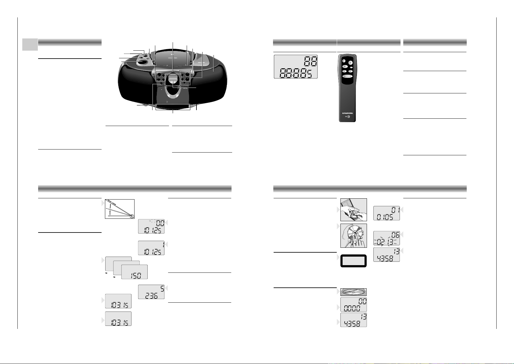
BEDIENELEMENTE
Ober- und Vorderseite
(die Abbildung zeigt: RR 750 CD)
VOLUME – zum Einstellen der Lautstärke
UBS –ein/aus des U
LTRA BASS SYSTEM
TONE –zum Einstellen des Klangs
(nur RR 710 CD)
FUNCTION
– CD: zum Umschalten auf CD-Betrieb
– TAPE: zum Umschalten auf
Cassettenbetrieb
– RADIO: zum Umschalten auf Radioempfang
SURROUND
SOUND –ein- und ausschalten des Surround-
sound-Effektes
(nur RR 750 CD)
REMOTE
SENSOR –
zum Empfang der Fernbediensignale
(nur RR 750 CD)
OPEN/CLOSE
–zum Öffnen des CD-Deckels
STAND BY 6– leuchtet auf, wenn das Gerät
eingeschaltet ist
MIC –eingebautes Mikrofon unter dem
Lautsprechergitter
p –Buchse für Stereo-Kopfhörer
STAND BY –ein/aus des Geräts
Cassette Control
(FUNCTION-Schalter auf position TAPE)
0 –Starten der Aufnahme
B –Starten der Wiedergabe
Q – schneller Rücklauf
R – schneller Vorlauf
9//
–Stoppen des Bandlaufs und Öffnen
des Cassettenfachs
; –unterbrechen der Wiedergabe/
Aufnahme
Radio Control
(FUNCTION-Schalter auf position RADIO)
MEMORY– zum Programmieren der Festsender
34 –
zum Abstimmen auf einen Radiosender
MEM-UP –
zur Auswahl der Senderspeicher
BAND –zum Wählen zwischen FM, MW,
und LW
Rückseite
BEAT CUT / FM MONO/STEREO:
– Zum Unterdrücken eventueller Pfeifgeräusche
bei MW/LW-Aufnahmen und zum Reduzieren
des Rauschens bei schwachem Empfang von
UKW-Stereo-Sendern.
AC MAINS: Netzanschlußbuchse
CD Control
(FUNCTION-Schalter auf position CD)
PLAY/PAUSE 2; –zum Starten/Unterbrechen der
Wiedergabe
STOP 9 –
zum Stoppen der Wiedergabe
RANDOM –zur Wiedergabe aller Titel in
zufälliger Reihenfolge
INTRO – zur Wiedergabe der ersten 10
Sekunden jedes Titels
MEMORY – zum Programmieren von Titeln
im Speicher
REPEAT – zum Wiederholen eines
Titels/aller Titel
∞/56/§ –
zum Überspringen von Stücken
(SKIP/SEARCH) und zum Suchen in Vorwärts-
oder Rückwärtsrichtung
C
D
S
Y
N
C
H
ROST
ARTR
E
C
O
R
D
I
N
G
R
R
7
5
0
C
D
R
A
D
IO
C
A
S
S
ETTE
R
E
C
O
R
D
E
R
W
I
T
H
C
D
OPEN/
CLOSE
PLAY/PAUSE
TUNER/CD
MEMORY
BAND
REMOTE
SENSOR
PLAYBACK/
RECORD
REMOTE CONTROL
R
R
7
5
0
C
D
RADIO
CASSE
T
T
E
R
E
C
O
R
D
E
R
W
IT
H
C
D
CD TAPE RADIO
/OFF
U
LT
R
A B
A
SS S
YST
E
M
UBS
SU
RRO
UND
SO
UND
VOLUME
MIN
RANDOM
INTRO
STAND BY
UP/FWD
DOWN/REW
REPEAT
MEM-UP
SKIP / SEARCH
L
O
W
-
TO
NE
-
HI
G
H
STOP
STAND BY
VOLUME
UBS
FUNCTION
SURROUND SOUND
REMOTE SENSOR
OPEN/CLOSE
Display
p
CD Control
Cassette Control
TONE
Radio Control
STAND BY
MIC
STAND BY 6
Display
Das Display zeigt:
RANDOM: während der Funktion RANDOM
REPEAT: Wiederholung aller Stücke
REPEAT
(blinkt): Wiederholung eines Stücks
INTRO: während der Funktion INTRO
MW/FM/LW: zeigt den ausgewählten
wellenbereich an
ST: leuchtet auf, wenn ein UKW-Stereo-
Sender empfangen wird
MEMORY: Programmieren oder Abspielen des
Programms (CD) oder
Senderspeicher
(Radio)
TRACK: zeigt CD-Stück an
CH: zeigt die Radiospeichernummer ein
88 Stücknummer (CD) oder
Speicherplatz (Radio)
88:8.85: Spielzeit (CD) oder Senderfrequenz
(Radio)
MHz/kHz: die Frequenz des empfangenen
Senders wird in MHz (FM) oder kHz
(MW) angezeigt
RANDOM
REPEAT
INTRO
MW FM ST
LW
MEMORY
TRACK
CH
MHz
kHz
BEDIENELEMENTE
Fernbedienung
(nur RR 750 CD)
Die Tasten an der Fernbedienung
haben die gleiche Funktion wie
die entsprechenden am Gerät.
Hinweis:
Bei der Stromversorgung über
Batterien kann die Taste y nur
zum Ausschalten des Geräts
verwendet werden.
Benutzen Sie zum Einstellen des
Geräts die STAND BY-Taste am
Gerät
(siehe 'Ein- und Ausschalten').
Batteriewechsel
Läßt die Reichweite Ihres IR-Gebers nach oder
lassen sich einzelne Funktionen nicht mehr
ausführen, sollten Sie die Batterien auswechseln.
Verwendeter Batterietyp 2x Micro 1,5 Volt LR03,
Größe AAA. Öffnen Sie zum Batteriewechsel den
Deckel des Batteriefaches auf der Rückseite des
Gebers. Achten Sie auf die richtige Polung der
Batterien (Markierung im Batteriefach beachten).
STOP
PREV./DOWN NEXT/UP
PLAY
VOLUME
MEM. UP
REPEAT
Volume
• Stellen Sie die gewünschte Lautstärke mit dem
VOLUME-Regler ein.
Tone
(nur RR 710 CD)
• Die Klangregulierung (TONE) ermöglicht Ihnen
die Einstellung von Höhen und Tiefen auf den
gewünschten Pegel.
UBS (Ultra Bass System)
• Drücken Sie die Taste UBS, um die Baßtone
hervorzuheben:
w UBS AUS
x UBS EIN
Surround Sound
(nur RR 750 CD)
Diese Funktion erstellt einen zusätzlichen 3-dimensionalen Effekt des Stereoklangs, der von den
Lautsprechern ausgetauscht wird.
• Drücken Sie SURROUND SOUND, um diesen
Effekt ein-und auszuschalten.
w SURROUND SOUND AUS
x SURROUND SOUND EIN
Kopfhörerbuchse p
• Sie können einen Stereo-Kopfhörer mit
3,5 mm
Stecker an die Buchse p anschließen.
– Die Lautsprecher werden damit abgeschaltet.
KLANGREGLER
Radioantennen
–
Bei UKW-Empfang (FM) die Teleskopantenne herausziehen und durch Neigen und Drehen ausrichten.
Bei
zu starkem UKW-Signal (in Sendernähe) empfiehlt
es sich die Antenne einzuschieben.
– Für
MW/LW-E
mpfang hat das Gerät eine eingebaute Antenne. Die Teleskopantenne kann also
eingeschoben bleiben. Zum Ausrichten der
Antenne das ganze Gerät drehen.
Rundfunkempfang
• Den FUNCTION-Schalter auf RADIO stellen.
• Den Ton mit den Reglern VOLUME, TONE
(nur RR
710 CD)
, UBS und
SURROUND SOUND
(nur RR
750 CD)
einstellen.
• Sie können einen Stereo-Kopfhörer mit
3,5 mm
Stecker an die Buchse p anschließen.
– Die Lautsprecher werden damit abgeschaltet.
• Den Wellenbereich mit der BAND-Taste wählen.
• Starten Sie den automatischen Sendersuchlauf,
indem Sie die Tasten 3 bzw. 4 ein oder zwei
Sekunden gedrückt halten und dann loslassen.
– Der Tuner sucht automatisch den ersten Sender
mit ausreichender Signalstärke.
•
Wiederholen Sie diese Schritte für weitere Sender.
• Um schwache Sender abzustimmen, drücken Sie
kurz auf die Taste 3/4 bis die richtige Frequenz angezeigt wird oder die Empfangsqualität optimal ist.
– Wenn die Angabe 'ST' erscheint, empfangen Sie
einen UKW-Stereo-Sender.
•
Treten bei
UKW
-Stereo-Empfang aufgrund einer nicht
ausreichenden Signalstärke Störungen auf, können
diese unterdrückt werden, indem FM MONO/
STEREO auf FM MONO geschaltet wird.
– Die 'ST'-Anzeige erlischt und der UKW-Sender
wird in Mono wiedergegeben.
Speichern von Stationen
Sie können bis zu 25 Stationen speichern.
(10 x FM, 10 x MW und 5 x LW).
• Den Wellenbereich mit der BAND-Taste wählen.
• Suchen Sie einen Sender durch Drücken der
Taste 3/4.
• Drücken Sie die Taste MEMORY.
– Die Anzeige 'MEMORY' fängt an zu blinken.
• Wählen Sie den Kanal, dem Sie eine Station
zuordnen möchten mit MEM UP.
•
Solange 'MEMORY' blinkt,
drücken Sie die Taste
MEMORY, um die Station zu speichern.
– Die Anzeige 'MEMORY' erlischt.
Im Display erscheint nun der senderbelegte
Kanal, die Frequenz und der Wellenbereich.
• Wenn Sie eine Station einem Kanal zuordnen,
der bereits mit einer Station belegt war, wird die
alte gelöscht und durch die neue ausgetauscht.
Stationswahl
• Den Wellenbereich mit der BAND-Taste wählen.
• Wählen Sie den gewünschten Speicherplatz mit
der Taste MEM UP.
– Die Speicherplatznummer, die Frequenz und der
Wellenbereich werden angezeigt.
Funktion 'Last Station Memory'
LAST STATION MEMORY bedeutet, das Gerät
merkt sich die jeweils zuletzt eingestellte Station.
Mit dieser Funktion läßt sich sicherstellen, daß der
Sender der vor dem Ausschalten eingestellt war
nach dem Einschalten wieder zu hören ist.
RADIO
FMST
MW
LW
kHz
Abspielen einer CD
•
Zum Starten des Abspielens auf PLAY/PAUSE 2;
drücken.
– Das Display zeigt die aktuelle Titelnummer und
die abgelaufene Spielzeit des Titels an.
• Den Ton mit den Reglern VOLUME, TONE
(nur RR
710 CD)
, UBS und
SURROUND SOUND
(nur RR
750 CD)
einstellen.
• Für kurzzeitige Unterbrechungen auf
PLAY/PAUSE 2; drücken.
– Die Zeitanzeige beginnt im Display zu blinken.
• Zum Fortsetzen der Wiedergabe die Taste
PLAY/PAUSE 2; erneut drücken.
• Zum Stoppen auf STOP 9 drücken.
–
Danach erscheint im Display die Gesamtspielzeit
und die Titelanzahl der CD.
– Der CD-Spieler geht ebenfalls in Stellung STOP:
– wenn Sie auf OPEN/CLOSE drücken;
– wenn das Ende der CD erreicht ist;
– wenn der FUNCTION-Schalter betätigt wird;
– wenn die Batterien ausgehen oder bei anderen
Stromunterbrechungen.
• Zum Herausnehmen der CD öffnen Sie den
Deckel durch Drücken der OPEN/CLOSE-Taste.
• Den CD-Deckel erst öffnen wenn sich der CDSpieler in Stellung STOP befindet.
Wahl eines anderen Titels während der Wiedergabe
•
Taste ∞/5 oder 6/§ drücken, bis die Nummer
des gewünschten Titels im Anzeigefeld erscheint.
– Der ausgewählte Titel wird sofort wiedergegeben.
Beginnen mit einem bestimmten Titel
•
Taste ∞/5 oder 6/§ drücken, bis die Nummer
des gewünschten Titels im Anzeigefeld erscheint.
• Taste PLAY/PAUSE 2; drücken.
– Die Wiedergabe beginnt beim Titel mit der
eingegebenen Nummer.
TRACK
TRACK
TRACK
TRACK
TRACK
CLASS 1
LASER PRODUCT
6
. O
Y
E
M
I C
A
N
T
O
(H
e
a
r
M
y
V
o
ic
e
)
7
. D
O
N
'T
W
A
N
N
A
L
O
S
E
Y
O
U
8
. G
E
T
O
N
Y
O
U
R
F
E
E
T
9
. Y
O
U
R
L
O
V
E
IS
B
E
D
F
O
R
M
E
1
0
. C
U
T
S
B
O
T
H
W
A
Y
S
1
1
. O
Y
E
M
I C
A
N
T
O
(S
p
a
n
is
h
V
e
r
s
io
n
)
1
2
. S
I V
O
Y
A
P
E
R
D
E
R
T
E
E
P
C
4
6
5
1
4
5
2
B
I
E
M
/
S
T
E
M
R
A
S
T
E
R
E
O
A
ll rig
hts o
f the
p
ro
d
u
c
e
r an
d
of th
e
o
w
n
e
r o
f th
e
rec
o
rd
e
d
w
o
rk re
served
. U
n
a
uth
o
rise
d
c
op
yin
g
,
p
u
b
lic p
erfo
rm
an
c
e
, b
roa
d
ca
stin
g
, hirin
g
o
r ren
ta
l o
f th
is
re
c
ord
in
g
p
roh
ib
ite
d
. M
ad
e in A
u
stria
1
. A
Y
, A
Y
, I
2
. H
E
R
E
W
E
A
R
E
3
. S
A
Y
4
. T
H
IN
K
A
B
O
U
T
Y
O
U
N
O
W
5
. N
O
T
H
IN
' N
E
W
C
O
M
P
A
C
T
D
I
G
I
T
A
L
A
U
D
I
O
1
2
Umgang mit CDs
• Nur digitale Audio-CDs verwenden. ( +)
• Um die CD aus der Box herauszunehmen, beim
Anheben der CD gegen die Mittenachse drücken.
• Die CD niemals beschriften oder mit einem
Aufkleber versehen.
• Fassen Sie die CD immer am Rande an und
legen Sie sie immer in die Verpackung zurück.
• Zum Reinigen die CD anhauchen und mit einem
weichen, nichtfasernden Tuch geradlinig von der
Mitte aus in Richtung des Randes abwischen.
Reinigungsmittel können die CD beschädigen!
•
Schützen Sie die CDs vor Regen und Feuchtigkeit,
vor Sand und vor Hitze z.B. von Heizgeräten oder
im Innenraum von in der Sonne geparkten Autos.
Warnung
CLASS 1 LASER PRODUCT bedeutet, daß der Laser
wegen seines technischen Aufbaus eigensicher ist,
so daß der maximal erlaubte Ausstrahlwert unter
keinen Umständen überschritten werden kann.
VORSICHT:
Wenn andere als die hier spezifizierten
Bedienungseinrichtungen benutzt oder andere
Verfahrensweisen ausgeführt werden, kann es zu
gefährlicher Strahlungsexposition kommen.
Einlegen einer CD
• Den FUNCTION-Schalter auf CD stellen.
•
Zum Öffnen des Deckels auf OPEN/CLOSE drücken.
• Die CD mit der bedruckten Seite nach oben
einlegen. Legen Sie CD-Singles (8 cm) in die
Vertiefung der Schublade.
• Den Deckel schließen.
–
Der CD-Spieler startet und tastet die Inhaltsangabe
der CD ab.
Danach erscheint im Display die Gesamtspielzeit
und die Titelanzahl der CD.
CD-SPIELER
FMST
FMST
FMST
FM
LW
MHz
MHz
MEMORY
CH
MHz
CH
MHz
CH
kHz
OIOIOI OI OIOIOI OIOIOIOI
OIOI OIOIOIOI OIOI
OIOIOO OIOI
OIOI OIOIO OIOI
OIOIOIOOIO OIOI OI
Page 5

RR 710 CD / RR 750 CD Allgemeiner Teil / General Section
GRUNDIG Service 1 - 5
Abspielen einer CD
Rasches Suchen einer Passage
• ∞/5 gedrückt halten, um in Richtung Plattenanfang zu suchen.
• 6/§ gedrückt halten, um in Richtung Plattenende zu suchen.
Hinweis:
Dies ist ein 'hörbares Suchen'.
Während des Suchens wird die Lautstärke reduziert
und nach dem Loslassen der Taste wird die
Lautstärke auf ihren normalen Wert zurückgestellt.
Random
• Drücken Sie RANDOM.
– Die Anzeige 'RANDOM' erscheint im Display.
• Drücken Sie PLAY/PAUSE 2;.
– Die Musiktitel werden in zufälliger Reihenfolge
abgespielt, bis jeder Titel einmal gespielt wurde.
• Drücken Sie die Taste RANDOM während der
Wiedergabe, wird das Abspielen in zufälliger
Reihenfolge ab Ende des aktuellen Titels gestartet.
• Die Funktion wird beendet, wenn Sie die Taste
STOP 9 oder RANDOM drücken; in diesem Fall
werden die nachfolgenden Stücke in gewohnter
Reihenfolge wiedergegeben.
•
Die Funktion 'RANDOM' ist nicht möglich, solange
Sie ein Programm abspielen.
Intro
• Drücken Sie die Taste INTRO, um jeweils nur die
ersten 10 Sekunden jedes Titels wiederzugeben.
–
Die Anzeige
'INTRO' erscheint im Display.
Der CD-Spieler beendet die Wiedergabe nach
dem letzten Titel.
• Die Funktion wird beendet, wenn Sie die Taste
STOP 9 oder INTRO drücken; in diesem Fall
werden die nachfolgenden Stücke normal
wiedergegeben.
Repeat
Wiederholung der CD
• Durch einmaliges Drücken von REPEAT werden
alle Musiktitel wiederholt.
– 'REPEAT' leuchtet auf; die CD wird jetzt ständig
wiederholt.
Wiederholung eines Titels
• Durch nochmaliges Drücken von REPEAT wird ein
Musiktitel wiederholt.
– 'REPEAT' fängt an zu blinken; der Titel wird jetzt
ständig wiederholt.
• Um den REPEAT-Modus auszuschalten, drücken
Sie die Taste REPEAT erneut oder STOP 9.
Programmieren
Sie können maximal 20 Titel in jeder beliebigen
Reihenfolge speichern. Beim Versuch mehr als 20
Titel zu speichern, wird die Programmierfunktion von
Anfang an wiederholt.
Speichern eines Programms
• Die Taste MEMORY drücken.
'MEMORY' und 'TRACK' blinken.
• Wählen Sie den gewünschten Titel mit den
Tasten
∞/5 oder 6/§.
• Speichern Sie diese Nummer durch Drücken der
MEMORY-Taste.
• Wählen und speichern Sie in dieser Weise alle
gewünschten Titel.
MEMORY
TRACK
REPEAT
TRACK
REPEAT
TRACK
INTRO
TRACK
RANDOM
TRACK
CD-SPIELER
Compact-Cassetten
– Copyright: Die Aufnahme ist nur im Rahmen der
Urheberrechte oder anderer Rechte Dritter
zulässig.
• Verwenden Sie für die Aufnahme nur NORMALCassetten (IEC
I), bei denen die Laschen nicht
herausgebrochen sind.
– Das Gerät ist nicht geeignet zum Aufnehmen auf
CHROME (IEC II) oder METAL (IEC IV) Cassetten.
• Für die Wiedergabe können Sie jedoch jeden
Cassettentyp einsetzen.
– Direkt am Anfang des Bandes erfolgt während
der ersten 7 Sekunden, wenn der transparente
Bandanfang vorbeiläuft, keine Aufnahme.
• Sie können eine Aufnahme vor unbeabsichtigtem
Löschen schützen: halten Sie die zu schützenden
Cassettenseite auf sich zugerichtet und brechen
Sie die Lasche linksoben heraus.
Jetzt läßt sich diese Seite nicht mehr bespielen.
• Zum Aufheben dieser Löschsperre decken Sie die
Öffnung mit einem Stück Klebeband ab.
• Schützen Sie die Cassetten vor Regen und
Feuchtigkeit, vor Sand und vor Hitze, z.B. von
Heizgeräten oder im Innenraum von in der Sonne
geparkten Autos.
• Vermeiden Sie das Aufbewahren der Cassetten
in der Nähe starker Magnetfelder (z.B. Fernsehgeräte, Lautsprecherboxen, Motoren etc.).
1
1
TRACK
MEMORY
TRACK
MEMORY
TRACK
Kontrolle des Programms
• In Stellung STOP, wenn Sie wiederholt die Taste
MEMORY drücken, zeigt das Display nacheinander alle gespeicherten Stücknummern in Reihenfolge.
– Anschließend erscheint die Angabe
'MEMORY'/'TRACK'/ 00 / P-....
•
Nun können Sie zu der aktuellen Reihenfolge, wie
oben beschrieben, bis zu 21 Titel speichern.
• Drücken Sie die Taste MEMORY noch einmal.
– Jetzt wird wieder der erste Titel des Programms
angezeigt.
Abspielen des Programms
• Drücken Sie einmal MEMORY, um den ersten
Titel des Programms anzeigen zu lassen.
• Taste PLAY/PAUSE 2; drücken.
–
Das Abspielen beginnt mit dem ersten Programmtitel.
–
Nach dem letzten Titel wird das Abspielen gestoppt.
–
Danach erscheint im Display die Gesamtspielzeit
und die Titelanzahl der CD.
Hinweise:
• Sie können das Abspielen durch Drücken der
Taste STOP 9 beenden.
•
Während des Abspielens eines Programms können
mit den Tasten ∞/5 oder 6/§ die gewünschten
programmierten Titel angewählt werden.
Löschen eines Programms
•
Um alle programmierten Titel zu löschen, drücken Sie
die Taste MEMORY und danach STOP 9 zweimal.
– Das Löschen von allen Titeln ist nur möglich,
wenn der CD-Spieler auf Stop geschaltet ist.
• Der Inhalt des Programms wird auch gelöscht:
– durch Öffnen des CD-Fachs mit OPEN/CLOSE;
– wenn der FUNCTION-Schalter betätigt wird;
– wenn die Batterien ausgehen oder bei anderen
Stromunterbrechungen.
CASSETTENDECKCD-SPIELER
Cassettenwiedergabe
• Den FUNCTION-Schalter auf TAPE stellen.
• Öffnen Sie den Cassettenhalter mit 9//.
• Legen Sie eine bespielte
Cassette ein.
• Den Ton mit den Reglern VOLUME, TONE
(nur
RR 710 CD)
, UBS und
SURROUND SOUND
(nur
RR 750 CD)
einstellen.
• Sie können einen Stereo-Kopfhörer mit 3,5 mm
Stecker an die Buchse
p anschließen.
– Die Lautsprecher werden damit abgeschaltet.
• Zum Starten des Abspielens auf B drücken.
• Für kurzzeitige Unterbrechungen auf
; drücken.
• Erneut auf ; drücken, wenn die Wiedergabe
fortgesetzt werden soll.
– Am Bandende wird die B-Taste entriegelt.
• Zum Stoppen auf 9// drücken.
Durch erneutes Drücken dieser Taste öffnet sich
das Cassettenfach.
Schneller Vor- und Rücklauf
• Drücken Sie R, um vorwärts bis an das Ende
des Bandes zu spulen.
• Drücken Sie Q, um rückwärts bis an den
Anfang des Bandes zu spulen.
CASSETTENDECK
Aufnahme
• Öffnen Sie den Cassettenhalter mit 9//.
• Legen Sie eine
Cassette ein.
• Beim Mithören der
Aufnahme, den Ton mit
den Reglern VOLUME,
TONE
(nur RR 710 CD)
,
UBS und
SURROUND SOUND
(nur RR 750 CD)
einstellen.
Die Stellung dieser Regler hat keinen Einfluß auf
die Aufnahme.
• Zum Aufnahmestart auf 0 drücken (die Taste B
rastet automatisch mit ein).
– Wenn das Bandende erreicht ist, werden die
Recordertasten freigegeben.
• Zum Unterbrechen der Aufnahme die Taste
;
drücken.
• Zum Fortsetzen der Aufnahme die Taste
; erneut
drücken.
•
Die Taste 9// drücken, wenn die Aufnahme vor
dem
Bandende gestoppt werden soll.
Durch erneutes Drücken dieser Taste öffnet sich
das Cassettenfach.
CD Synchro – Aufnahme vom CD-Spieler
• Den FUNCTION-Schalter auf CD stellen.
• Sie brauchen den CD-Spieler nicht separat zu
starten: sobald Sie auf 0 drücken, startet der
CD-Spieler automatisch.
– Steht der CD-Spieler in Stellung STOP, startet
die Aufnahme vom Anfang der CD (oder vom
Anfang des gespeicherten Programms).
• Um eine Aufnahme in der Mitte eines Stücks zu
starten, beginnen Sie die CD-Wiedergabe wie
gewohnt.
• Sobald die gewünschte Passage erreicht ist,
drücken Sie auf Pause und anschließend auf 0,
um die Aufnahme zu starten.
Aufnahme vom Radio
• Den FUNCTION-Schalter auf RADIO stellen.
•
Den Wellenbereich mit der BAND-Taste wählen.
• Wählen Sie die gewünschte Station mit den
Tasten 3/4 oder MEM UP.
• Bei Aufnahmen von UKW-Sendern den Schalter
FM MONO/STEREO auf die gewünschte
Position stellen.
• Wenn während der Aufnahme eines MW/LWSenders Pfeifgeräusche zu hören sind, können
diese unterdrückt werden, indem der Schalter
BEAT CUT auf die andere Position gestellt wird.
Mono-Aufnahme vom eingebauten Mikrofon
• Den FUNCTION-Schalter auf TAPE stellen.
• Den VOLUME-Regler auf Null stellen (ein
Mithören während Mikrofonaufnahmen ist nicht
möglich).
• Um eine gute Aufnahme zu gewährleisten, sollte
ein Abstand von 30 – 100 cm zum Mikrofon
eingehalten werden.
Page 6
Allgemeiner Teil / General Section RR 710 CD / RR 750 CD
1 - 6 GRUNDIG Service
GB
Operating Instructions
Note: This chapter contains excerpts from the operating instructions. For further particulars please refer to the
appropriate user instructions the part number of which is indicated in the relevant spare parts list.
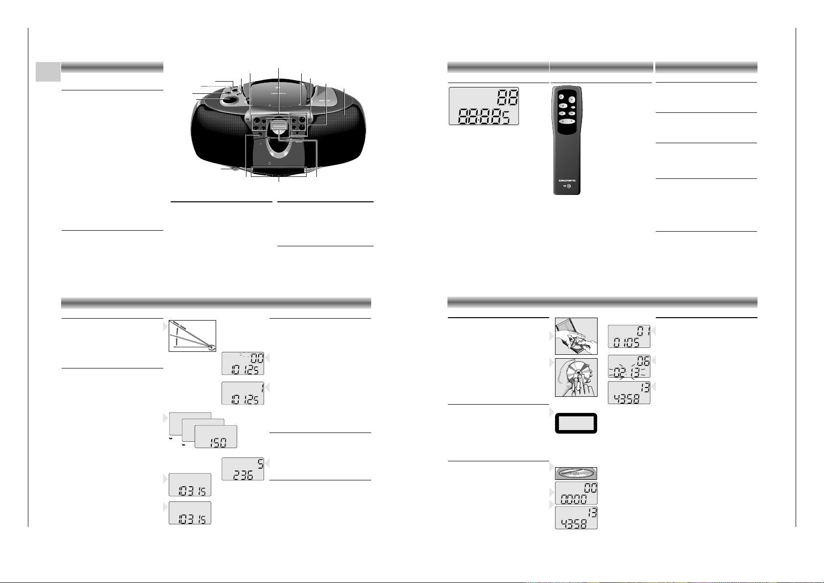
CONTROLS
Top and front panel
(the illustration shows: RR 750 CD)
VOLUME – to adjust the volume.
UBS –to switch the U
LTRA BASS SYSTEM on
and off
TONE –to adjust the tone
(only RR 710 CD)
FUNCTION
– CD: to switch to CD mode
– TAPE: to switch to TAPE mode
– RADIO: to switch to RADIO mode
SURROUND
SOUND –to switch the surround sound
effect
on and off
(only RR 750 CD)
REMOTE
SENSOR –to receive the remote signals
(only RR 750 CD)
OPEN/CLOSE
–to open the CD door
STAND BY 6– lights up when the unit is on
MIC –built-in microphone under the
speaker grill
p –connection for headphones
STAND BY –to switch the unit on and off
Cassette Control
(FUNCTION switch in position TAPE)
0 –to start recording
B –to start cassette playback
Q – fast rewind
R – fast forward
9// –to stop and eject the cassette
; –to interrupt playback/recording
Radio Control
(FUNCTION switch in position RADIO)
MEMORY –to store the radio stations
34 –to tune to a radio station
MEM-UP –
to select the memory positions
BAND – to select between FM, MW,
and LW waveband
Back panel
BEAT CUT / FM MONO/STEREO:
– For eliminating possible whistle tones during
MW/LW recordings and reduce noise caused
by weak FM stereo stations.
AC MAINS: Socket for mains lead.
CD Control
(FUNCTION switch in position CD)
PLAY/PAUSE 2; –to start and interrupt playback
STOP 9 –to stop playback
RANDOM – to play the titles of a CD in
random order
INTRO – to play only the first 10
seconds of each title
MEMORY – to programme track numbers in
the memory
REPEAT – to repeat one/all tracks
∞/56/§ – to skip and search
(SKIP/SEARCH) backward/forward
C
D
S
Y
N
C
H
ROST
ARTR
E
C
O
R
D
I
N
G
R
R
7
5
0
C
D
R
A
D
IO
C
A
S
S
ETTE
R
E
C
O
R
D
E
R
W
I
T
H
C
D
OPEN/
CLOSE
PLAY/PAUSE
TUNER/CD
MEMORY
BAND
REMOTE
SENSOR
PLAYBACK/
RECORD
REMOTE CONTROL
R
R
7
5
0
C
D
RADIO
CASSE
T
T
E
R
E
C
O
R
D
E
R
W
IT
H
C
D
CD TAPE RADIO
/OFF
U
LTR
A
B
AS
S
SY
S
TE
M
UBS
SU
RRO
UND
S
OUND
VOLUME
M
IN
RANDOM
INTRO
STAND BY
UP/FWD
DOWN/REW
REPEAT
MEM-UP
SKIP / SEARCH
L
O
W
-
TO
NE
-
HI
G
H
STOP
STAND BY
VOLUME
UBS
FUNCTION
SURROUND SOUND
REMOTE SENSOR
OPEN/CLOSE
Display
p
CD Control
Cassette Control
TONE
Radio Control
STAND BY
MIC
STAND BY 6
Display
The display indicates:
RANDOM: during the RANDOM function
REPEAT: repeat all
REPEAT
(flashing): repeat one
INTRO: during the INTRO function
MW/FM/LW: indicates the selected waveband
ST: lights up when receiving FM stereo
stations
MEMORY: programming or programme play-
back (CD) or storing stations (radio)
TRACK: indicates the CD track
CH: indicates the radio memory channel
88 track number (CD) or memory
channel (radio)
88:8.85: playing time (CD) or station
frequency (radio)
MHz/kHz: for FM reception the frequencies are
indicated in MHz and for MW/LW
reception in kHz
RANDOM
REPEAT
INTRO
MW FM ST
LW
MEMORY
TRACK
CH
MHz
kHz
CONTROLS
Remote control
(only RR 750 CD)
The buttons on the remote control
have the same functions as the
corresponding buttons on the unit.
Note:
When using battery supply, the y
button can only be used to switch
the unit off.
To switch the unit on when using
battery supply, use the STAND BY
button on the set
(see 'Switching on and off').
Changing batteries
If the range of your infrared remote control seems to
decrease, or if certain functions can no longer be
carried out, you should replace the batteries.
Two mignon 1.5 Volt LR03, size AAA batteries are
required.
To change the batteries, open the compartment on
the back of the remote control. Ensure that the
batteries are inserted properly (note the markings in
the compartment).
STOP
PREV./DOWN NEXT/UP
PLAY
VOLUME
MEM. UP
REPEAT
Volume
• Adjust the volume to the desired level with the
VOLUME control.
Tone
(only RR 710 CD)
• The TONE control allows you to adjust the bass
and treble values to the desired level.
UBS (Ultra Bass System)
• Press UBS to enhance the bass response:
w UBS OFF
x UBS ON
Surround Sound
(only RR 750 CD)
This feature creates an additional 3-D effect from
stereo sound which is relayed by the speakers.
• Press SURROUND SOUND to switch this effect on
and off
w SURROUND SOUND OFF
x SURROUND SOUND ON
Stereo headphone socket p
• You may connect stereo headphones having a
3.5 mm plug to the jack p.
– Inserting the plug will disconnect the speakers.
SOUND CONTROL
Radio aerials
–
For FM, pull out the telescopic aerial. To improve
FM-reception, incline and turn the aerial.
Reduce its length if the FM-signal is too strong
(very close to a transmitter).
– For MW/LW, the set is provided with a built-in
aerial, so the telescopic aerial is not needed.
Direct the aerial by turning the whole set.
Radio reception
• Set the FUNCTION switch to RADIO.
• Adjust the sound using the VOLUME, TONE
(only
RR 710 CD)
, UBS and SURROUND SOUND
(only RR 750 CD)
controls.
• You may connect stereo headphones having a
3.5 mm plug to the jack p.
– Inserting the plug will disconnect the speakers.
• Select the wave band using the BAND button.
• Start the automatic station search by holding the
3 or 4 button down for one or two seconds, and
then releasing it.
– The tuner automatically searches for the first
station with sufficient signal strength.
• Repeat this step to search for other stations.
• To tune to a weak station, briefly press the 3/4
buttons several times until the correct frequency is
displayed, or until reception is best.
– When 'ST' appears on the display, you are
receiving an FM stereo transmitter.
• A disturbing noise, due to a weak FM stereo
signal, can be suppressed by setting
FM MONO/STEREO to FM MONO.
– The 'ST' indication goes out and you will hear the
FM station in mono.
Storing stations
You can store a maximum of 25 stations
(10 x FM, 10 x MW and 5 x LW).
• Select the wave band using the BAND button.
• Select the desired station with the 3/4 buttons.
• Press the MEMORY button.
– 'MEMORY' starts flashing on the display.
• Select the channel you wish to assign to this
station with MEM UP.
•
While 'MEMORY' is flashing
, press MEMORY to
store this station.
– 'MEMORY' disappears from the display.
The display now indicates the station's assigned
channel, its frequency and waveband.
• If you assign a station to a channel that had been
previously assigned to a different station, the old
station is deleted and replaced by the new one.
Selecting stations
• Select the wave band using the BAND button.
• Select the desired memory channel with the
MEM UP button.
– The display indicates the selected channel, the
station frequency and waveband.
Last station memory
LAST STATION MEMORY means that the unit
'remembers' the last station that was tuned to.
This function ensures that the station which was
selected before the radio was switched off is
automatically selected again when your radio is
switched back on.
RADIO
FMST
MW
LW
kHz
Playing a CD
• Press PLAY/PAUSE 2; to start playback.
– The display shows the current track number and
its elapsed playing time.
• Adjust the sound using the VOLUME, TONE
(only
RR 710 CD)
, UBS and SURROUND SOUND
(only RR 750 CD)
controls.
• For brief interruptions, press PLAY/PAUSE 2;.
– The playing time indication starts flashing.
•
To resume playback, press PLAY/PAUSE 2; again.
• To stop playback, press STOP 9.
– The total playing time and number of tracks will
then appear on the display.
– The CD player also goes to position STOP:
– by pressing OPEN/CLOSE;
– when the end of the CD is reached;
– if the FUNCTION switch is moved to another
position
– if the batteries run down or if the power supply
is interrupted.
• To take out the CD, open the CD door by pressing OPEN/CLOSE.
• Open the CD door only if the CD player is in
position STOP.
Selecting another track during play
• Press ∞/5 or 6/§ until the required track
number appears in the display.
– The selected track begins to play.
Starting with a particular track
• Press ∞/5 or 6/§ until the required track
number appears in the display.
• Press PLAY/PAUSE 2;.
– Play starts from the selected track.
TRACK
TRACK
TRACK
TRACK
TRACK
CD handling
• Use only Digital Audio CDs which have the
symbol +.
• To take the CD out of its box easily, press the
centre spindle while lifting the CD.
•
Never write on a CD or attach any sticker to the CD.
• Always hold the CD at the edge and always
store it in its box after use with the label facing up.
• To remove dust and dirt, breathe on the CD and
wipe it with a soft, lint-free cloth in a straight line
from the center towards the edge. Cleaning
agents may damage the CD.
• Do not expose the CD to rain, moisture, sand, or
to excessive heat. (E.g. from heating equipment
or in motor cars parked in the sun).
Warning
CLASS 1 LASER PRODUCT means that the laser´s
construction makes it inherently safe so that the
legally prescribed maximum permissible ratiation
values can never be exceeded.
CAUTION: Using any equipment or devices other
than those described and specified in these operating instructions, or tampering with the unit in any
way, can result in dangerous exposure to radiation.
Inserting a CD
• Set the FUNCTION switch to CD.
• Press OPEN/CLOSE to open the CD door.
• Insert the CD, printed side facing up. Place CD
singles (8 cm) in the depression in the compartment.
• Close the cover.
– The CD player scans the contents list of the CD.
After that, the total number of tracks and the total
playing time appear on the display.
CD PLAYER
MEMORY
CH
FMST
FMST
FMST
FM
LW
MHz
MHz
MHz
CH
MHz
CH
kHz
2
,
g
yin
p
o
ustria
c
d
1
. A
Y
, A
in A
2
Y
. H
rise
e
, I
E
o
R
d
E
3
W
. S
a
th
E
A
A
Y
u
R
4
. T
E
a
. M
H
n
IN
5
K
. N
A
B
O
ited
. U
O
T
H
U
IN
T
d
ib
Y
' N
O
h
E
U
W
N
rve
O
ro
W
se
p
1
ing
rk re
rd
o
o
c
w
re
ed
is
rd
f th
co
l o
re
e
ta
n
r of th
or re
g
ne
E
P
C
4
irin
6
5
B
1
I
E
e ow
4
M
5
, h
/
S
2
T
E
g
M
S
R
T
A
f th
E
R
E
O
o
astin
nd
c
C
O
M
P
A
r a
C
ad
T
e
ro
uc
d
D
I
G
I
e, b
T
A
L
ro
c
A
U
D
n
I
O
p
a
e
rm
f th
rfo
6
. O
e
ts o
Y
E
M
h
7
p
. D
I C
O
A
N
lic
N
'T
8
T
. G
W
O
b
ll rig
(H
E
A
T
u
N
e
O
9
A
N
a
. Y
r
A
p
N
M
L
Y
O
y
O
O
U
V
S
U
R
1
E
0
o
R
L
. C
Y
ic
F
O
e
O
E
V
U
)
U
E
E
T
1
T
IS
S
1
B
. O
B
O
E
Y
T
D
E
H
1
M
F
2
W
. S
O
I C
A
R
I V
Y
A
M
S
N
O
E
T
Y
O
A
(
P
S
p
E
a
R
n
D
is
E
h
R
V
T
e
E
r
s
io
n
)
CLASS 1
LASER PRODUCT
OIOIOI OI OIOIOI OIOIOIOI
OIOI OIOIOIOI OIOI
OIOIOO OIOI
OIOI OIOIO OIOI
OIOIOIOOIO OIOI OI
Page 7
RR 710 CD / RR 750 CD Allgemeiner Teil / General Section
GRUNDIG Service 1 - 7
Playing a CD
Searching for a passage during play
• Hold ∞/5 down to search backwards to the
beginning.
• Hold 6/§ down to search
forwards to the end.
Note:
This function can be described as 'audibly'
searching for a title.
During the search, volume is reduced and returns to
its adjusted level as soon as the button is released.
Random
• Press the RANDOM button.
– 'RANDOM' lights up on the display.
• Press PLAY/PAUSE 2;.
– The tracks are played in random order until all of
them have been played once.
• By pressing RANDOM during playback, random
play starts from the end of the playing track.
• The function is deactivated by pressing STOP 9
(in which case the CD stops) or RANDOM; in this
case the remaining tracks are played in their
normal order.
• The random function is not possible during
playback of a programme.
Intro
• Press INTRO to play only the first 10 seconds of
each title.
– 'INTRO' lights up on the display.
After the last title, the CD player stops.
• The function is deactivated by pressing STOP 9
(in which case the CD stops) or INTRO; in this
case the remaining tracks are played back in the
normal way.
Repeat
Repeating the CD
• By pressing REPEAT once, all tracks are
repeated.
– 'REPEAT' lights up; the CD will now be repeated
continuously.
Repeating a track
• By pressing REPEAT twice, one track is repeated.
– 'REPEAT' starts flashing; the track will now be
repeated continuously.
• To switch the repeat mode off, press REPEAT one
more time, or press STOP 9.
Programming
By programming the player you can play up to 20
tracks in any desired order. If you exceed the
maximum of 20 tracks, the programme function will
start again from the beginning.
Storing a programme
• In STOP mode, press MEMORY.
'MEMORY' and 'TRACK' start flashing.
•
Select the first desired track using ∞/5 or 6/§.
• Store this track by pressing MEMORY again.
• Select and store in this way all desired titles.
MEMORY
TRACK
REPEAT
TRACK
REPEAT
TRACK
INTRO
TRACK
RANDOM
TRACK
CD PLAYER
Compact cassettes
– Copyright: Recording is permissible insofar as
copyright or other rights of third parties are not
infringed.
• For recording, use a NORMAL (IEC type
I)
cassette on which the tabs are not broken out.
– This deck is not suited for recording on CHROME
(IEC II) or METAL (IEC IV) cassettes.
• For playback, any cassette type may be inserted.
– At the very beginning and end of the tape, no
recording will take place during the few seconds
when the leader tape passes the recorder heads.
• To prevent the accidental erasure of a recording,
keep the cassette side to be safeguarded in front
of you and break out the left tab.
Now, recording on this side is no longer possible.
• To render this safeguard ineffective, cover the
hole with a piece of adhesive tape.
• Do not expose the cassettes to rain, moisture,
sand, or to excessive heat. (E.g. from heating
equipment or in motor cars parked in the sun)
• Do not store cassettes near strong magnetic fields
(for example, TV sets, speakers, engines, etc.).
1
1
TRACK
MEMORY
TRACK
MEMORY
TRACK
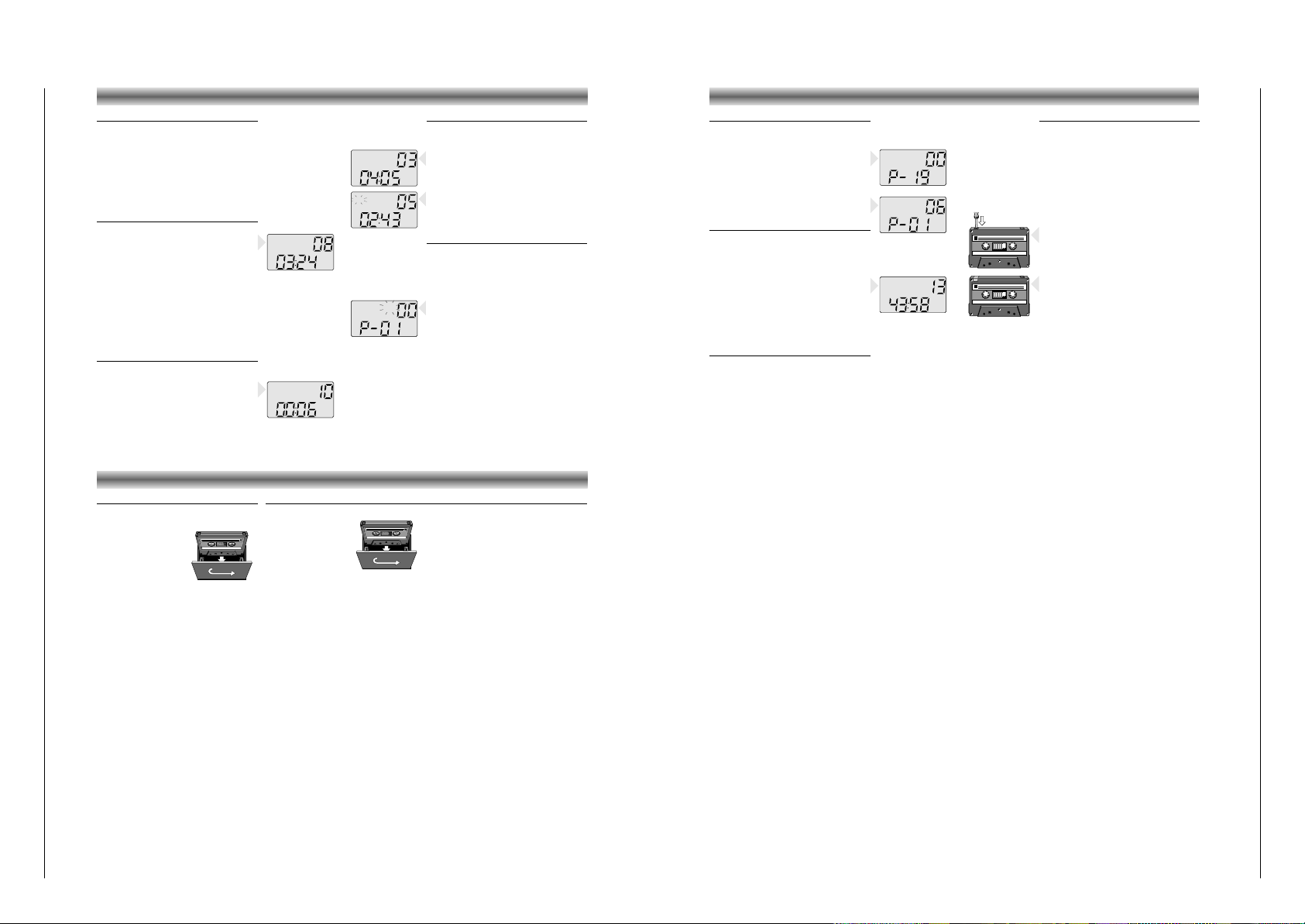
Checking the programme
• In STOP mode, press MEMORY repeatedly.
– The display shows in sequence all programmed
track numbers.
– Then, 'MEMORY'/'TRACK'/ 00 / P-...
appears again.
• At this point you can also add more tracks to the
programme (up to 20).
• Press MEMORY one more time.
– The display will show the first track of the
programme again.
Playing a programme
• Press MEMORY once to show the first track of the
programme.
• Press PLAY/PAUSE 2;.
– Play starts with the first track of the programme.
– After the last track playback stops.
– The CD's total playing time and number of tracks
appear on the display.
Note:
• Press STOP 9 to stop playback.
• While playing a programme, it is possible to use
∞/5 or 6/§ to select the desired
programmed tracks.
Erasing a programme
• To clear the programme, press the MEMORY
button and afterwards STOP 9 twice.
– You can only erase the programme when the CD
player is stopped.
• The programme is also erased:
– by opening the CD door using OPEN/CLOSE;
– if you move the FUNCTION selector;
– if the batteries are exhausted or if the power
supply is interrupted in another way.
CASSETTE DECKCD PLAYER
Cassette playback
• Set the FUNCTION switch to TAPE.
• Press 9// to open the cassette holder.
• Insert a recorded
cassette.
• Adjust the sound using the
VOLUME, TONE
(only
RR 710 CD)
, UBS and
SURROUND SOUND
(only
RR 750 CD)
controls.
• You may connect stereo headphones having a
3.5 mm plug to the jack
p.
– Inserting the plug will disconnect the speakers.
• Press B and playback will start.
• For brief interruptions, press
;.
• To restart playback, press this button once more.
– When the end of the tape is reached the B
button is released.
• To stop, press 9//.
On pressing again, the cassette holder will open.
Winding the tape
• Press R to search forward to the end of the
tape.
• Press Q to search backward to the beginning
of the tape.
CASSETTE DECK
Cassette recording
• Press 9// to open the cassette holder.
• Insert the cassette.
• When monitoring during
recording, adjust the
sound using the controls VOLUME, TONE
(only
RR 710 CD)
, UBS and SURROUND SOUND
(only RR 750 CD)
.
These controls do not affect the recording.
• Start recording by pressing 0.
(the B button is automatically also pressed).
– When the end of the tape is reached, the
recorder buttons are released.
• To interrupt recording, press
;.
• To continue recording, press ; again.
• Press 9// if you want to stop recording before
the end of the tape.
On pressing again, the cassette holder will
open.
Recording from the CD player
(CD synchro recording)
• Set the FUNCTION switch to CD.
• It’s not necessary to start the CD player separately: by pressing 0 the CD player starts
automatically.
– If the CD player is in STOP position, recording
will start from the beginning of the CD (or from
the beginning of the programmed selection).
• To start a recording in the middle of a track,
play the CD in the normal way.
• As soon as the desired passage is reached,
pause the CD and then start recording by
pressing 0.
Recording from the radio
• Set the FUNCTION selector to RADIO.
• Select the wave band using the BAND button.
• Select the desired station with the 3/4 or MEM
UP buttons.
• In case of FM radio recordings, set the
FM MONO/STEREO switch to the desired
position.
• If during the recording of an MW/LW station,
a whistling sound is heard, this sound can be
suppressed by setting the BEAT CUT switch to
another position.
Mono recording from the built-in microphone
• Set the FUNCTION switch to TAPE
• Set the VOLUME control to the minimum volume
level (during microphone recording, monitoring
is not possible).
• To ensure a clear recording, the distance to
microphone should be 30 – 100 cm.
Page 8
Allgemeiner Teil / General Section RR 710 CD / RR 750 CD
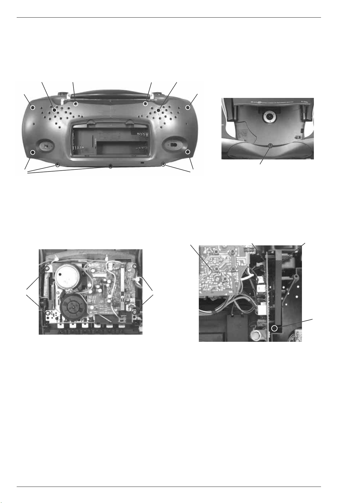
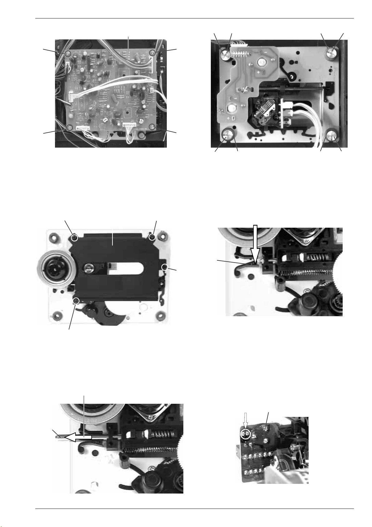
Ausbauhinweise
1. Gehäusevorderteil abnehmen
- 2 Schrauben A (lang) und 7 Schrauben B (kurz) herausdrehen
(Fig. 1).
- Schraube C im CD-Fach (Fig. 2) herausdrehen.
- Gehäusevorderteil nach vorne abnehmen.
- Bei Bedarf Steckverbindungen abziehen.
A
E
E
B
Disassembly Instructions
1. Removing the Cabinet Front
- Undo 2 screws A (long) and 7 screws B (short) (Fig. 1).
- Undo the screw C in the CD compartment (Fig. 2).
- Remove the front of the cabinet towards the front.
- Disconnect the plug-in connections if necessary.
A
B
C
BB
Fig. 1
2. Cass.-Laufwerk ausbauen, (Fig. 3)
- Gehäusevorderteil abnehmen (siehe Pkt. 1).
- 4 Schrauben D herausdrehen.
- Cassettenfachdeckel durch Drücken der Taste STOP/EJECT
öffnen.
- Laufwerk herausnehmen.
- Eventuell Kabelbinder lösen.
2. Dismantling the Cassette Drive Mechanism, (Fig. 3)
- Remove the cabinet front (see para 1).
- Undo 4 screws D.
- Open cassette compartment lid by pressing the buttton STOP/
EJECT.
- Take out the cassette drive mechanism.
- Eventually loosen the cable ties.
Fig. 2
Bedienplatte
Control PCB
Tunerplatte
Tuner PCB
DD
Fig. 3 Fig. 4
3. Chassis ausbauen, (Fig. 1 und 4)
- Gehäusevorderteil abnehmen, (siehe Pkt. 1).
- 2 Schrauben E herausdrehen (Fig. 1).
- Schraube F herausdrehen (Fig. 4).
- Chassis (mit Lautstärkereglerplatte, Tunerplatte, Bedienplatte, CDTeil) nach vorne herausnehmen.
- Bei Bedarf Steckverbindungen abziehen.
4. CD-Laufwerk ausbauen
Bei Ausbau der CD-Lasereinheit muß vor Abziehen der Steckver-
bindungen eine Schutzlötstelle G auf der Leiterplatte der Lasereinheit angebracht werden, um eine Zerstörung der Laserdiode
durch statische Aufladung zu vermeiden (Fig. 10).
- Chassis ausbauen (siehe Pkt. 3).
- 4 Schrauben H (Fig. 5) herausdrehen.
- Steckverbindungen von der CD-Leiterplatte abziehen.
- CD-Leiterplatte abnehmen.
- 4 Schrauben I herausdrehen (Fig. 6).
- CD-Laufwerk herausnehmen.
Achten Sie dabei auf die Puffer (Fig. 6) J (schwarz) und K (blau).
Diese Puffer haben einen unterschiedlichen Auflagedruck
(schwarz = stärker, blau = schwächer).
3. Removing the Chassis, (Fig. 1 and 4)
- Remove the cabinet front (see para 1).
- Undo 2 screws E (Fig. 1).
- Undo the screw F (Fig. 4).
- Remove the chassis towards the front (with volume control PCB,
tuner PCB, control PCB, CD unit).
- Disconnect the plug-in connections if necessary.
4. Removing the CD Mechanism
When removing the Laser pick-up, the pick-up PCB must be provided
with a protective soldered joint G before unplugging the connectors to avoid damage to the Laser diode by static charges (Fig. 10).
- Remove the chassis (see para 3).
- Undo 4 screws H (Fig. 5).
- Unplug the connectors from the CD circuit board.
- Take out the CD circuit board.
- Undo 4 screws I (Fig. 6).
- Remove the CD mechanism.
Take care of the buffers J (black) and K (blue) Fig. 6. The buffer
pressure is different (black = stronger, blue = weaker).
Chassisrahmen
Chassis frame
F
1 - 8 GRUNDIG Service
Page 9
RR 710 CD / RR 750 CD Allgemeiner Teil / General Section
CD-Leiterplatte
CD PCB
IJ K I
HH
H
Fig. 5
5. Lasereinheit ausbauen
- CD-Laufwerk ausbauen (siehe Pkt. 4).
- 4 Schrauben L herausdrehen und Abdeckblech M abnehmen
(Fig. 7).
- Sperre N vorsichtig in Pfeilrichtung 1 drücken (Fig. 8).
- Führungsstange O in Pfeilrichtung 2 schieben und Lasereinheit
abnehmen (Fig. 9).
H
I
5. Removing the Laser Pick-Up
- Remove the CD drive mechanism (see para 4).
- Undo 4 screws L and remove the cover plate M (Fig. 7).
- Push the locking device N carefully in the direction of the arrow 1
(Fig. 8).
- Move the guide rail O in the direction of arrow 2 and remove the
laser pick-up (Fig. 9).
J
Fig. 6
K
I
L
ML
L
L
Achtung beim Einbau einer neuen Lasereinheit:
Die Laserdiode ist gegen statische Aufladung beim Transport kurzgeschlossen. Nach dem Einbau und Anschluß der Lasereinheit muß
die Kurzschlußlötstelle G (Fig. 10) auf der Laseranschlußplatte
aufgelötet werden.
Verstellen Sie nicht den Regler für die Laserstromeinstellung!
Der Laserstrom wurde werkseitig eingestellt.
Fig. 7
2
1
N
Fig. 8
Attention when fitting the new pick-up:
The laser diode is short-circuited for protection against static charges
during transportation. After fitting the laser unit the soldered short
circuit G (Fig. 10) on the laser connection board must be opened.
Do not turn the variable resistor (laser power adjustment).
The laser current is pre-set at the factory.
Laseranschlußplatte
G
Laser PCB
O
Fig. 10Fig. 9
GRUNDIG Service 1 - 9
Page 10

Einstellvorschriften / Adjustment Procedures RR 710 CD / RR 750 CD
>1V
0
j
Einstellvorschriften
1. CD-Teil
Meßgeräte/Meßmittel: Oszilloskop
Hinweis: Verstellen Sie nicht den Regler für die Laserstromeinstellung! Der Laserstrom wurde werkseitig eingestellt.
Abgleichlageplan siehe Seite 2 - 3.
Abgleich Vorbereitung Abgleichvorgang
Tracking Balance
Oszilloskop an Stecker CN106/1 (TSO),
Masse an CN106/3 (VREF).
Mit VR102 Kurve symmetrisch zur 0-Linie (Vref)
einstellen.
- CD einlegen
- CD-Fachdeckel schließen
- CD-Funktion: T oder S (SEARCH)
Focus Offset
Oszilloskop an Stecker CN106/2 (RFO),
Masse an CN106/3 (VREF).
Mit VR101 einen sauberen Kurvenverlauf (Augenmuster)
einstellen.
- CD einlegen
- CD-Fachdeckel schließen
- CD-Funktion: PLAY
2. Cassettenteil
Meßgeräte/Meßmittel: Frequenzzähler, NF-Voltmeter, Tonhöhenschwankungsmesser,
Fe-Testcassette 449 (Sach-Nr. 35079-019.00), Drehmomentcassette 456 (Sach-Nr. 35079-014.00).
Abgleichlageplan siehe Seite 2 - 3.
Abgleich Vorbereitung Abgleichvorgang
1. Bandgeschwindigkeit
Frequenzzähler an Kopfhörerbuchse.
Testcassette 449 einlegen, 3150Hz abspielen.
Mit dem Einstellregler (im Cass.-Motor)
3150Hz ±0,1% einstellen.
DC Input
V1=V2
MOTOR
V1
V2
Max.
0
(Vref)
2. Aufwickelmoment bei Start
3. Gleichlauf
4. Kopfspaltsenkrechtstellung
(Azimut)
5. Vormagnetisierungsfrequenz
6. Vormagnetisierungsspannung
Drehmomentcassette 456 einlegen.
Funktion: Wiedergabe-Start.
Tonhöhenschwankungsmesser an Kopfhörerbuchse.
Testcassette 449 einlegen, 3150Hz abspielen.
NF-Voltmeter an Kopfhörerbuchse.
Testcassette 449 einlegen,
8kHz abspielen.
Frequenzzähler an TP6 (A/W-Kopf).
Bespielbare Cassette einlegen.
Gerätefunktion: Aufnahme-Start.
NF-Voltmeter über einen kapazitiven Spannungsteiler
1:1000 an TP6 (A/W-Kopf).
Bespielbare Cassette einlegen.
Gerätefunktion: Aufnahme-Start.
Bandzug bei:
Wiedergabe-Start = 35 - 65g-cm
Schnellvorlauf = 50 - 120g-cm
Schnellrücklauf = 50 - 120g-cm
Gleichlaufabweichung < 0,35% (gehörrichtig bewertet).
Wiedergabemeßzeit ≥ 30 Sekunden.
Mit der Kopfeinstellschraube 1
den linken und rechten Kanal auf
1
Pegelmaximum einstellen.
Der Pegelunterschied von Kanal zu
Kanal darf maximal 3dB betragen.
Oszillatorfrequenz 60kHz ± 10kHz.
Die Vormagnetisierungsspannung beträgt ca. 10V
(gemessen mit einem kapazitiven Spannungsteiler 1:1000).
2 - 1 GRUNDIG Service
Page 11

RR 710 CD / RR 750 CD Einstellvorschriften / Adjustment Procedures
3. Tuner
Meßgeräte: Meßsender, Wobbelsender, Oszilloskop, Digitalvoltmeter.
Funktionsschalter: Radio
Abgleichlageplan siehe Seite 2 - 3.
Abgleich Vorbereitung Abgleichvorgang
1. AM-ZF
2. MW Oszillator
3. MW Vorkreis
4. LW Oszillator
5. LW Vorkreis
6. FM-ZF
Wobbelsender 455kHz über Rahmenantenne in Ferrit-
antenne einkoppeln.
Oszilloskop an Meßpunkt TP4 (IC302 Pin6).
Bandschalter: MW
MW 1620kHz
Digital-Voltmeter an Meßpunkt TP5 (VT).
Bandschalter: MW
MW 558kHz, MW 1440kHz
Meßsendersignal über Rahmenantenne in Ferritanten-
ne einkoppeln (f
Oszilloskop an Kopfhörerbuchse.
= 1kHz, m = 30%, Ua <).
mod
Bandschalter: MW
LW 285kHz
Digital-Voltmeter an Meßpunkt TP5 (VT).
Bandschalter: LW
LW 160kHz, LW 280kHz
Meßsendersignal über Rahmenantenne in Ferritanten-
ne einkoppeln (f
Oszilloskop an Kopfhörerbuchse.
= 1kHz, m = 30%, Ua <).
mod
Bandschalter: LW
Wobbelsender 10,7MHz über 4pF an Meßpunkt TP2
(IC301, Pin4).
Oszilloskop an Meßpunkt TP3 (IC302, Pin9).
Bandschalter: FM
Mit T302 auf Maximum einstellen.
Bei 1620kHz mit T303 (VT) 7,5V ± 0,2V einstellen.
Abgleich Pkt. 2 und Pkt. 4 wechselseitig wiederholen.
Bei 522kHz (VT) 1,1V ± 0,3V überprüfen.
Bei 558kHz mit MW-Antennenspule (verschieben) auf
Maximum einstellen.
Bei 1440kHz mit TC302 auf Maximum einstellen.
Abgleich wechselseitig wiederholen.
Bei 285kHz mit TC304 (VT) 7,5V ± 0,2V einstellen.
Abgleich Pkt. 2 und Pkt. 4 wechselseitig wiederholen.
Bei 150kHz (VT) 0,8V ± 0,3V überprüfen.
Bei 160kHz mit LW-Antennenspule (verschieben) auf
Maximum einstellen.
Bei 280kHz mit TC303 auf Maximum einstellen.
Abgleich wechselseitig wiederholen.
Mit T301 auf Maximum einstellen.
7. FM Oszillator
8. FM Vorkreis
FM 108MHz
Digital-Voltmeter an Meßpunkt TP5 (VT).
Bandschalter: FM
FM 88MHz, FM 106MHz
Meßsendersignal an Meßpunkt TP1 (FM-Ant.),
(f
= 1kHz, ∆f = 40kHz, Ua <).
mod
Oszilloskop an Kopfhörerbuchse.
Bandschalter: FM
Bei 108MHz mit L303 (VT) 6V ± 0,3V einstellen.
Bei 87,5MHz (VT) 1,3V ± 0,5V überprüfen.
Bei 88MHz mit L302 (verbiegen) auf Maximum einstellen.
Bei 106MHz mit TC301 auf Maximum einstellen.
Abgleich wechselseitig wiederholen.
GRUNDIG Service 2 - 2
Page 12

Einstellvorschriften / Adjustment Procedures RR 710 CD / RR 750 CD
Abgleichlagepläne
Alignment Schemes
Tuner
CD
TP5
TP1
TP2
CN305
B2
B1
Stereo
VT
IF
MUTE
TC301
TC302
TC303
TC304
D301
D302
T303
R302
L302
IC301
TP4
TP3
T301
RR 710/750CD
L303
T302
IC302
6
9
Ferrit-Ant.MW LW
1
Cassette
TP6
2 - 3 GRUNDIG Service
Page 13

RR 710 CD / RR 750 CD Einstellvorschriften / Adjustment Procedures
k
Adjustment Procedures
1. CD-Section
Measuring instruments: Oscilloscope
Note: Do not turn the variable resistor (laser power adjustment). The laser current is pre-set at the factory.
Alignment scheme see page 2 - 3.
Adjustment Preparations Adjustment Processs
Tracking Balace
Connect the Oscilloscope to connector CN106/1 (TSO),
ground to CN106/3 (VREF).
Adjust VR102 so that the graph is Symmetrical to the 0-line
(Vref).
- Load a CD
- Close the CD door
- CD Function: T or S (SEARCH)
Focus Offset
Connect the Oscilloscope to connector CN106/2 (RFO),
ground to CN106/3 (VREF).
Adjust VR101 to obtain a clear eye pattern as shown in the
diagram.
- Load a CD
- Close the CD door
- CD Function: PLAY
0
2. Cassette Deck
Measuring instruments/equipment: Frequency counter, AF-voltmeter, wow and flutter meter,
Fe test cassette 449 (Part No. 35079-019.00), torque test cassette 456 (Part No. 35079-014.00).
Alignment scheme see page 2 - 3.
Adjustment Preparations Adjustment Process
1. Tape speed
Connect the frequency counter to the headphone socket.
Insert the test cassette 449, play 3150Hz.
With adjustment control (in the
cass.-motor) set the frequency
to 3150Hz ±0.1%.
DC Input
V1=V2
MOTOR
>1V
Max.
V1
0
(Vref)
V2
2. Take-up torque on
Start
3. Wow and flutter
4. Head gap angle
(Azimuth)
5. Bias frequency
6. Bias voltage
Insert the torque test cassette 456.
Function: Playback-Start.
Connect the wow and flutter meter to the headphone
socket. Insert test cassette 449, play 3150Hz.
Connect the AF-voltmeter to the headphone socket.
Insert test cassette 449,
play 8kHz.
Connect the frequency counter to TP6 (R/P head).
Insert a recordable cassette.
Function: Record-Start.
Connect the AF-voltmeter via a 1:1000 capacitive voltage
divider to TP6 (R/P head). Insert a recordable cassette.
Function: Record-Start
Tape tension on: Playback-Start = 35 - 65g-cm
Fast Forward = 50 - 120g-cm
Fast Rewind = 50 - 120g-cm
Deviation < 0.35% (aurally compensated). Playback
measuring time ≥ 30 seconds.
With the head adjustment screw 1 set the
1
left and right channel to maximum level.
The levels of the two channels mustnot
differ by more than 3dB.
The oscillator frequency should be 60kHz ± 10kHz.
The bias voltage is approx. 10V (measured with a 1:1000
capacitive voltage divider).
GRUNDIG Service 2 - 4
Page 14

Einstellvorschriften / Adjustment Procedures RR 710 CD / RR 750 CD
3. Tuner
Measuring instruments: Signal Generator, Sweep Generator, Oscilloscope, Digital Voltmeter.
Function switch: Radio
Alignment scheme see page 2 - 3.
Adjustment Preparations Adjustment Process
1. AM IF
2. MW Oscillator
3. MW Aerial
bandpass
4. LW Oscillator
5. LW Aerial
bandpass
6. FM IF
Couple in a sweep signal of 455kHz to ferrite aerial via
a loop aerial.
Oscilloscope to testpoint TP4 (IC302 Pin6).
Band switch: MW
MW 1620kHz
Digital voltmeter testpoint TP5 (VT).
Band switch: MW
MW 558kHz, MW 1440kHz
Couple in a standard signal to ferrite aerial via a loop
aerial, (f
Oscilloscope to the headphone socket.
= 1kHz, m = 30%, Ua <).
mod
Band switch: MW
LW 285kHz
Digital voltmeter testpoint TP5 (VT).
Band switch: LW
LW 160kHz, LW 280kHz
Couple in a standard signal at to ferrite aerial via a loop
aerial, (f
Oscilloscope to the headphone socket.
= 1kHz, m = 30%, Ua <).
mod
Band switch: LW
Feed in a 10.7MHz sweep signal via 4pF to testpoint TP2
(IC301, Pin4).
Oscilloscope to testpoint TP3 (IC302, Pin9).
Band switch: FM
Adjust T302 to maximum.
At 1620kHz adjust to (VT) 7.5 ± 0.2V with T303.
Repeat the adjustment para 2 and para 4.
At 522kHz check (VT) 1.1 ± 0.3V.
At 558kHz adjust to maximum with MW antenna coil
(move).
At 1440kHz adjust to maximum with TC302.
Repeat this adjustment.
At 285kHz adjust to (VT) 7.5 ± 0.2V with TC304.
Repeat the adjustment para 2 and para 4.
At 150kHz check (VT) 0.8 ± 0.3V.
At 160kHz adjust to maximum with LW antenna coil
(move).
At 280kHz adjust to maximum with TC303.
Repeat this adjustment.
Adjust T301 to maximum.
7. FM Oscillator
8. FM Aerial
bandpass
FM 108MHz
Digital voltmeter testpoint TP5 (VT).
Band switch: FM
FM 88MHz, FM 106MHz
Couple in the standard signal to TP1 (FM ant.),
(f
= 1kHz, ∆f = 40kHz, Ua <).
mod
Oscilloscope to the headphone socket.
Band switch: FM
At 108MHz adjust to (VT) 6V ± 0.3V with L303.
At 87.5Hz check (VT) 1.3 ± 0.5V.
At 88MHz adjust to maximum with L302 (bend).
At 106MHz adjust to maximum with TC301.
Repeat this adjustment.
2 - 5 GRUNDIG Service
Page 15

RR 710 CD / RR 750 CD Schaltpläne und Druckplattenabbildungen / Circuit Diagrams and Layout of PCBs RR 710 CD / RR 750 CD Schaltpläne und Druckplattenabbildungen / Circuit Diagrams and Layout of PCBs
Schaltpläne und Druckplattenabbildungen / Circuit Diagrams and Layout of PCBs
Verdrahtungsplan / Wiring Diagram
3
R/P HEAD
TRAFO
AC SOCKET
CASSETTE BOARD
R G L
•
CONDENSOR
•
MIC
BEAT CUT
BOARD
FM ANTENNA
FM-ANT.
TUNER BOARD
CONTROL BOARD
(LCD DISPLAY BOARD)
CN304
8
•
2
+
CN205
–
CN201
CN501
CN502
2
AC
AC
+12V
GND
3
11
2
FUSE BOARD
CN804
CN306
(CN305)
•
CN301
•
CN302
•
2
6
CN202
CN204
CN203
2
11
5
STANDBY
BATTERIES
CD MAIN BOARD
10
- +
SPEAKERS
+ -
4
+ -
CASS. DECK
AF / POWER BOARD
CN608
•
CN609
3
CN606
CN604
2
•
CN602
CN601
3
•
•
•
CN605
CN603
•
CN102
CN104
•
TONE CONTROL BOARD
(VOLUME BOARD)
CN406
•
CN403
CN402
5
2
3
CN404
•
8
CN401
•
CN405
•
2
3
6
to CD Motor Board
•
CN108
CN101
•
CN109 CN107
•
8
LASER HEAD
BOARD
CN103
•
2
•
8
•
•
CD DOOR
SWITCH
BEI DEN IN DEN SCHALTPLÄNEN ANGEGEBENEN MESSWERTEN HANDELT ES SICH UM NÄHERUNGSWERTE!
THE MEASURED VALUES GIVEN IN THE CIRCUIT DIAGRAMS ARE APPROXIMATES!
GRUNDIG Service GRUNDIG ServiceGRUNDIG ServiceGRUNDIG Service3 - 1 3 - 2
Page 16

Schaltpläne und Druckplattenabbildungen / Circuit Diagrams and Layout of PCBs RR 710 CD / RR 750 CD Schaltpläne und Druckplattenabbildungen / Circuit Diagrams and Layout of PCBs RR 710 CD / RR 750 CD
Tuner
0.7V (0.7V)
3.5V
3.4V
(4.5V)
0V
(0V)
0V
(0V)
2.2V
(4.4V)
(0.4V)
(0V)
TO CN501
4.3V
(3.8V)
0V
(4.5V)
4.3V
(3.9V)
0V
BEAT CUT
BOARD
PAGE 3-5
2.1V
(0.4V)
0.7V
(0.4V)
0.1V
(0V)
3.5V
(0V)
0V
(0V)
0V
(0V)
0V
(0V)
0V
(0V)
0V (0V)
0.6V
(0.6V)
0V
(0V)
0V
(0V)
0V
(0V)
3.5V
(4.5V)
4.1V
(0.5V)
0V
(0V)
0V
(0V)
0V
(0V)
2.6V
(4.2V)
B C E
Tuner Board
Bestückungsseite / Component Side
3.3V
(4.4V)
2.8V
(3.8V)
3.5V
(4.5V)
GLEICHSPANNUNGEN GEGEN GND i GEMESSEN.
DC-VOLTAGES MEASURED AGAINST GND i.
V = FM (V) = MW
VOLTAGES IC301 TA7358AP
PIN 123456789
V FM 0.7 1.5 2.7 1.5 0 3.0 1.8 2.8 2.8 2.6
VOLTAGES IC302 TA8132AN
PIN 123456789101112
V FM 3.4 3.4 3.5 3.5 3.5 2.8 0.9 0 3.5 0 0 0
V MW 4.4 4.4 4.5 4.1 4.5 4.0 0.2 0 4.5 0.2 5.5 0
PIN 13 14 15 16 17 18 19 20 21 22 23 24
V FM 1.0 1.0 2.7 2.3 2.6 0.6 1.7 2.7 3.5 3.3 3.5 3.8
V MW 1.0 1.0 4.0 4.5 4.2 0.6 1.3 4.0 4.5 3.8 4.5 4.5
TA7358AP
TA 7358 A
RF
AMP
*
BIASRF
OUT
IN
BUFFER
AMP
MIX
51 2 3 4 6 7 8 9
GND VCCOSCOSCRF
MIX
MIX
IN
OUT
BIAS
OSC
VOLTAGE
REGULATOR
TA8132AN
VCO
LPF2
LPF1
MPX In
Detect Out
Quad
AM IF In
Bypass
Mix. Out
FM IF In
24 23 22 21 20 19 18 17 16 15 14 13
FM
AM
IF
AM
Det.
Osc. Out
Dec.
ECL
VCO
AM/FM
Mono Sw.
Level
Switch
AGC Switch
Vcc
AM Low Cut
AGC
IF Req.
IF Out
ECL
Tun.
LED
Tun. LED
AM
Mix.
AF IF In
FM
IF
SSC Osc.
FM IF Divider
AM Osc.
TO CN405
TONE CONTROL
BOARD
PAGE 3-13
TO CN201
CONTROL BOARD
PAGE 3-12
TO CN202
CONTROL
BOARD
PAGE 3-12
L ch. Out
Decoder
HYS
TA 8132 AN
Stereo
LED
Stereo LED
R ch. Out
121110987654321
Ground
GRUNDIG Service GRUNDIG Service3 - 3 3 - 4
Page 17

RR 710 CD / RR 750 CD Schaltpläne und Druckplattenabbildungen / Circuit Diagrams and Layout of PCBs RR 710 CD / RR 750 CD Schaltpläne und Druckplattenabbildungen / Circuit Diagrams and Layout of PCBs
BA 3313 L
ALC
INPUT 1 INPUT 2OUTPUT 1
OUTPUT 2ALC
GND
FILTERVCC
1 3 5 7 9 11
2 4 6 8
+
-
+
-
10 12
NF 2NF 1
GND
(SUB)N.C.
Cassette
2.0V
REC.
-1.3V
REC.
0.5V
REC. 6.8V
GLEICHSPANNUNGEN GEGEN GND i GEMESSEN.
DC-VOLTAGES MEASURED AGAINST GND i.
VOLTAGES IC U501 BA3313L
PIN 123456789101112
V
(REC) 2.6 0.3 0.6 0 0.1 0 0 6.2 0.1 6.2 0.6 2.6
V (PLAY) 2.9 0 0.6 0 0 0 0 6.8 0 6.8 0.6 2.9
0.75V
0.1V
Cassette Board
Bestückungsseite / Component Side
E
C
B
Beat Cut Board
Bestückungsseite / Component Side
GRUNDIG Service GRUNDIG ServiceGRUNDIG ServiceGRUNDIG Service3 - 5 3 - 6
B
C
E
Page 18

Schaltpläne und Druckplattenabbildungen / Circuit Diagrams and Layout of PCBs RR 710 CD / RR 750 CD Schaltpläne und Druckplattenabbildungen / Circuit Diagrams and Layout of PCBs RR 710 CD / RR 750 CD
CD
VCC 4.3V
3.8V
3.8V
GND
3.8V
3.8V
4.3V
7.7V
3.8V
46
MDI
COSC
17
2.1V
2V
45
44
3.8V
2.1V
FPI
LDO
IC103
TA2065BF
OSC1
GND
18
19
0V
2.1V
43
FNI
VCC
20
5.0V
2.1V
42
TN0
SEL
21
41
40
1.8V0V0V
TN1
DMEP
22
23
5.0V
2.1V
TPI
DMEN
2.1V
39
TSN
TEL2
TEL1
TSO
TS1P
TS1N
TS2P
TS2N
TS2O
THLD
FMSP
FMSN
FMSO
24
TPO
DF
DMEO
1.8V
0V
38
2.1V
37
2.1V
36
2.1V
35
2.1V
34
2.1V
33
32
2.1V
31
2.1V
30
2.1V
29
28
2.1V
27
2.1V
26
2.1V
25
2.1V
TO
LASER
HEAD
BOARD
)
4.4V
NOT
CONNECTED
48
47
2.1V0V0V
1
RFT
RFN
RFO
2.0V
2
RFI
2.1V
3
807978777675747372717069686766
X1
X0
GX
GNDA1
1
2
3
4
5
6
7
8
9
10
11
12
13
14
15
16
17
18
19
0V
0V
0V
5V
0V
0V
4.9V
20
21
22
23
24
VDDX
RO
R-O
VDA
L-0
LO
GNDA2
TEST3
TEST4
TEST5
SBCK
VDD
GNDD1
BUS0
BUS1
BUS2
BUS3
CCE
BUCK
PFCK
RST
SUBSYC
SUBD
CLCK
V1
GND2
DFCT
TEL2
252627282930313233343536373839
AOUT
DOUT
EMPH
TEST2
IC103
TC9284BF
TEL1
TGUL
TGUH2
TGUH1
BCK
TKIC
CHCK
FMON
WDCK
TEST-1
COFS
FMFB
SPDA
TEST
65
VCDF
GNDD
TESTY
LPFO
LPFN
TMAX
PDO
PDCNT
VDDA
DTSC1
MONIT
DTSC2
GNDA3
VREF
RFRP
SBAD
TEOF
TESH
FEL1
FEL2
FKIC
FCSI
2VREF
DMOND1D2
40
SEL
TX
64
63
62
61
60
59
58
57
56
55
54
RFI
53
52
51
50
49
48
FEI
47
46
45
44
43
42
41
VRO
2.1V
4
ZVRO
4.2V
5
RFRP
2.6V
6
SBAD
0V
7
DFIN
0V
8
FEP
2.1V
9
FEN
2.1V
10
FEO
2.1V
11
FEI
2.1V
12
FHLD
2.0V
13
FEL1
2.1V
14
FEL
2.1V
2CT
FSN
FSD
15
16
2.1V
2.1V
0V
0V
GLEICHSPANNUNGEN BEI "PLAY" GEGEN MASSE (GND) GEMESSEN.
DC-VOLTAGES MEASURED AGAINST MINUS TERMINAL (GND) ON "PLAY".
5V8V
7.4V
CH1
OUTA
GND3
VOLTAGES IC102 TC9284BF
PIN 1 2 3 4 5 6 7 8 9 10 11 12 13 14 15 16 17 18 19 20 21 22 23 24
V 0 2.8 3.0 5.0 3.0 2.8 0 - - - - 5.0 0 4.1 4.0 4.0 4.0 3.5 4.4 2.3 5.0 0 0 0
PIN 25 26 27 28 29 30 31 32 33 34 35 36 37 38 39 40
V 5.0 0 - 2.1 2.1 2.1 - 2.1 1.7 2.1 - 1.8 - 2.1 2.1 2.4
PIN 41 42 43 44 45 46 47 48 49 50 51 52 53 54 55 56 57 58 59 60 61 62 63 64
V 4.2 5.0 2.5 2.5 2.1 2.1 2.1 2.1 2.1 2.3 2.6 2.6 2.1 0 2.4 5.0 0 0 0 2.1 2.1 2.1 2.0 1.3
PIN 65 66 67 68 69 70 71 72 73 74 75 76 77 78 79 80
V 0 5.0 0 0 1.6 2.5 2.5 2.5 2.5 0 2.4 5.0 5.0 - 2.2 0
VOLTAGES IC104 KA9258D
PIN 1234567891011121314
V 3.8 3.7 2.1 2.1 7.4 0 0 0 2.1 2.1 4.2 3.2 0 7.6
PIN 15 16 17 18 19 20 21 22 23 24 25 26 27 28
V - - 3.7 3.7 - 2.1 8.0 8.0 2.1 2.1 - 3.7 3.7 0
INA
CH1
CH1
OUTB
CH4
OUTA
CH4
OUTB
CH4
TO
CD MOTOR
BOARD
INB
CH1
TR-B
MUTE
VREG.
INA
CH4
INB
BIAS
VCC2
GND1
VCC1
CH2
CH3INB
INB
INA
CH2
CH2
CH2
OUTB
OUTA
GND2
OPOUT
or
CH3
INA
CH3
OUTB
CH3
OUTA
OPIN+
OPIN-
IC104
KA9258D
BA639FB
)
TO
LASER
HEAD
BOARD
)
DREHTELLERMOTOR
TURN TABLE MOTOR
SCHLITTENMOTOR
SLED MOTOR
CD MOTOR BOARD
+
-
+
-
INNEN-SCHALTER
INNER SWITCH
SP+
SP-
SL+
SLL.SW
L.SW
TO
CN108
FOCUS
S
TRACK
LASER HEAD BOARD
LD
GND
PD
VR
TO
FCS-
CN109
TRKTRK+
FCS+
GND
D
C
B
A
TO
CN107
K
E
F
3 - 7
GRUNDIG Service GRUNDIG Service3 - 8
Page 19

RR 710 CD / RR 750 CD Schaltpläne und Druckplattenabbildungen / Circuit Diagrams and Layout of PCBs RR 710 CD / RR 750 CD Schaltpläne und Druckplattenabbildungen / Circuit Diagrams and Layout of PCBs
CD Board
Bestückungsseite / Component Side
TC9284BF
TA2065BF
KA4558
GRUNDIG Service GRUNDIG ServiceGRUNDIG ServiceGRUNDIG Service3 - 9 3 - 10
KA9258
Page 20

Schaltpläne und Druckplattenabbildungen / Circuit Diagrams and Layout of PCBs RR 710 CD / RR 750 CD Schaltpläne und Druckplattenabbildungen / Circuit Diagrams and Layout of PCBs RR 710 CD / RR 750 CD
Bedienteil / Control Board
TC9309AF
STANDBY
5.1V
5.1V
5.2V
5.0V
4.3V
2.4V
4.8V
5.1V
1.1V
1.1V
1.1V1.1V
0.6V
2.4V
0.18V
0.18V
0.18V
0.18V
2.4V
0.18V
2.4V
3.3V
0V
0.2V
0.2V
0.2V
5.5V
0V
0V
1.0V
0V
Control Board
Bestückungsseite / Component Side
GLEICHSPANNUNGEN BEI FUNKTION CD-"STOP" GEGEN MASSE (GND) GEMESSEN.
DC-VOLTAGES MEASURED AGAINST MINUS TERMINAL (GND) ON FUNCTION CD-"STOP".
GRUNDIG Service GRUNDIG Service3 - 11 3 - 12
Page 21

RR 710 CD / RR 750 CD Schaltpläne und Druckplattenabbildungen / Circuit Diagrams and Layout of PCBs RR 710 CD / RR 750 CD Schaltpläne und Druckplattenabbildungen / Circuit Diagrams and Layout of PCBs
Klangregelung / Tone Control
2.1V
3.1V
3.1V
1.5V
0.6V
0.6V
0.9V
0.9V
VOLUME
(RR 710 CD)
VOLUME
(RR 710 CD)
NOT
CONNECTED
2.1V
1.5V
Tone Control Board (Volume)
Bestückungsseite / Component Side
GRUNDIG Service GRUNDIG ServiceGRUNDIG ServiceGRUNDIG Service3 - 13 3 - 14
Page 22

Schaltpläne und Druckplattenabbildungen / Circuit Diagrams and Layout of PCBs RR 710 CD / RR 750 CD Schaltpläne und Druckplattenabbildungen / Circuit Diagrams and Layout of PCBs RR 710 CD / RR 750 CD
NF-Teil und Stromversorgung / AF Part and Power Supply
I602
BA5053
BLOCK A
0V
0V
0V
0V
6.2V
0V
0V 7V
0V
0V
0V
7V
0V
7.1V
0V
0V
0V
0V
7.1V
7.1V
RR 710 CD: Alle Bauteile in Block A nicht bestückt, JP651 + JP652 geschlossen.
Omit all components in Block A, connect JP651 + JP652.
RR 750 CD: Alle Bauteile in Block A bestückt, JP651 + JP652 geöffnet.
Put all components in Block A, omit JP651 + JP652.
15.5V
7.7V
15.2V
15.5V
8.2V
0.6V
RR 710 150Ω
RR 750 100Ω
0V
0V
0V
0V
0.6V
0V
0V
7.7V
15.2V
15.5V
RR 710 150Ω
RR 750 100Ω
15V
HEADPHONE
15.5V
(CD)
8.0V
6.2V
12V
15V
14.8V
15.5V
S
FUSE
F801
T 2AL /
250V
7.8V
0.6V
15.5V
15.5V 15.5V
BA5053
S
S
5.5V
0V
0.6V
(CD)
15.1V
3
1
2
(CD)
14.3V
(CD)
15.3V
0V
0V
15.7V
7.7V
8.3V
(CD)
0.08V
(CD)
0.6V
KA22066
GRUNDIG Service GRUNDIG Service3 - 15 3 - 16
Page 23
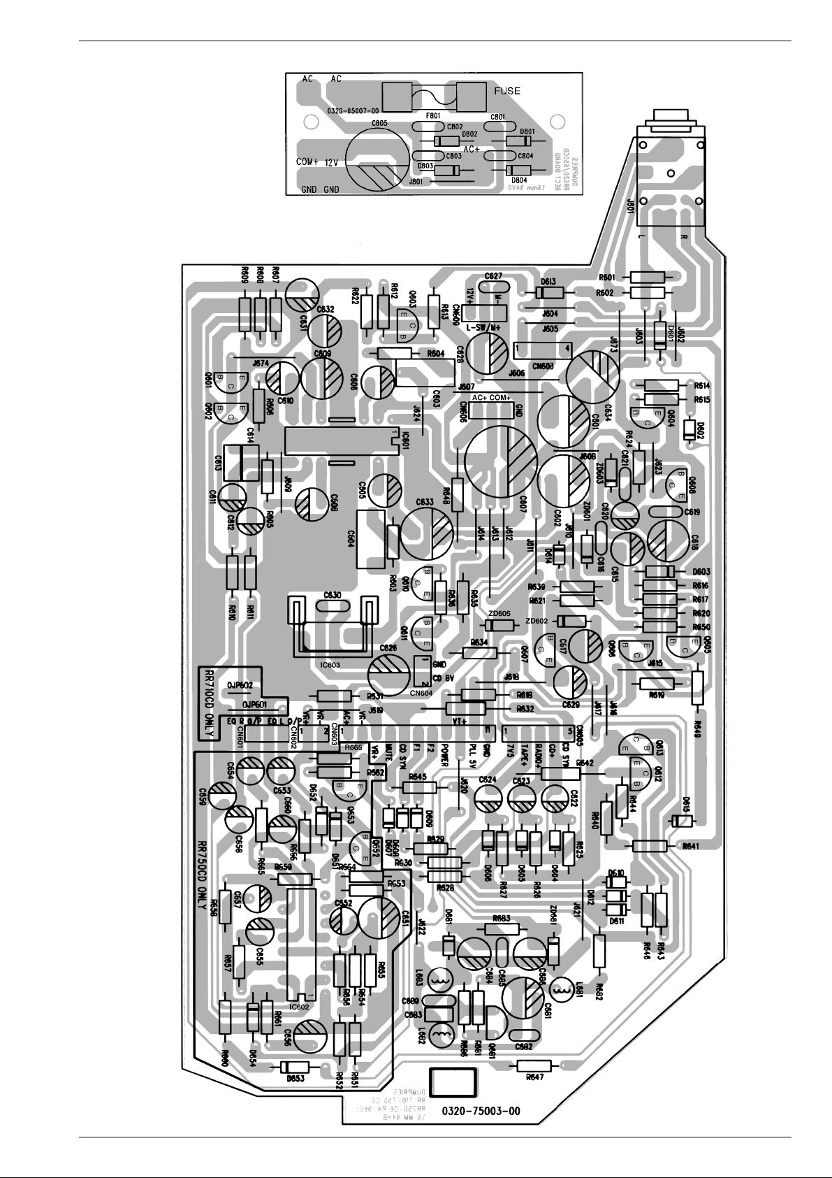
RR 710 CD / RR 750 CD Schaltpläne und Druckplattenabbildungen / Circuit Diagrams and Layout of PCPs
1
2
3
Fuse Board
Bestückungsseite
Component Side
AF / Power Board
Bestückungsseite / Component Side
GRUNDIG Service 3 - 17
Page 24
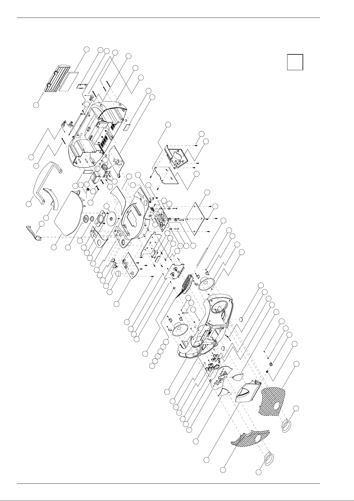
Ersatzteillisten und Explosionszeichnungen / Spare Parts Lists and Exploded Views RR 710 CD / RR 750 CD
Ersatzteillisten und Explosionszeichnungen / Spare Parts Lists and Exploded Views
Explosionszeichnung RR 710 CD / Exploded View RR 710 CD
42
43
44
45
46
47
48
49
50
41
101
51
52
53
1
40
39
96
97
98
38
37
36
33
35
34
32
31
100
99
88
90
91
89
92
95
94
93
30
29
28
27
26
25
24
23
22
87
86
85
84
83
82
81
80
79
21
20
19
18
17
16
15
14
13
12
54
55
56
57
58
59
76
77
78
75
74
73
60
61
62
63
64
65
66
67
68
69
70
71
11
10
9
8
7
6
5
4
3
2
1
72
4 - 1 GRUNDIG Service
Page 25

BEZEICHNUNG
DESCRIPTION
SACHNUMMER
PART NUMBER
POS. NR.
POS. NO.
BEZEICHNUNG
DESCRIPTION
SACHNUMMER
PART NUMBER
POS. NR.
POS. NO.
D
POS. NR.
ABB.
SACHNUMMER ANZ.
POS. NO.
FIG.
PART NUMBER QTY.
BEZEICHNUNG
DESCRIPTION
D
GB
BEZEICHNUNG
DESCRIPTION
SACHNUMMER
PART NUMBER
POS. NR.
POS. NO.
BEZEICHNUNG
DESCRIPTION
SACHNUMMER
PART NUMBER
POS. NR.
POS. NO.
GRUNDIG Service 4 - 2
Ersatzteilliste
Spare Parts List
11 / 96
SACH-NR. / PART NO.:
BESTELL-NR. / ORDER NO.:
0001.000 1 75954-046.67 ABDECKBLENDE R COVER MASK R
0002.000 1 75954-046.96 LAUTSPRECHER GITTER L SPEAKER GRILLE L
0003.000 1 75954-047.41 TUER CASS DOOR CASS.
0004.000 1 75954-046.43 LINSE, TUER CASS. LENS DOOR CASS.
0005.000 1 75954-047.01 FRONTBLENDE FRONT MASK
0006.000 1 75954-046.57 2 LINSE, POWER LENS POWER
0007.000 1 75954-047.05 KNOPF, CD KONTROLL L2 KNOB, CD CONTROL L2
0008.000 1 75954-047.04 KNOPF, CD KONTROLL L1 KNOB, CD CONTROL L1
0011.000 1 75954-046.38 GEHAEUSEVORDERTEIL CABINET FRONT
0012.000 1 75954-046.58 KNOPF REC, CASS KNOB REC, CASS
0013.000 1 75954-046.59 KNOPF PLAY, CASS. KNOB PLAY, CASS
0014.000 1 75954-046.60 KNOPF REW CASS KNOB REWIND CASS
0015.000 1 75954-046.61 KNOPF FF, CASS KNOB FF, CASS
0016.000 1 75954-046.62 KNOPF STOP/EJEKT, CASS KNOB STOP/EJEKT, CASS
0017.000 1 75954-046.63 KNOPF PAUSE, CASS KNOB PAUSE, CASS
0020.000 1 75954-046.87 CASS LAUFW. TK20FX-S818-003 CASS. DRIVE MECHANISN TK20FX-S818-003
0024.000 1 75954-046.95 VOLUME KNOPF VOLUME KEY
0025.000 1 75954-046.75 KNOPF UBS KNOB UBS
0026.000 1 75954-047.08 KNOPF TON KNOB TONE
0027.000 1 75954-046.74 KNOPF, FUNKTIONSCHALTER KNOB FUNCTION SWITCH
0028.000 1 75954-046.42 CD KONSOLE CD DRAWER
0030.000 1 75954-047.03 ABDECKBLENDE L COVER MASK L
0032.000 1 75954-046.36 HALTER HOLDER
0033.000 1 75954-046.78 MAGNETHALTER MAGNET HOLDER
0034.000 1 75954-046.84 MAGNET MAGNET
0035.000 1 75954-047.09 TUER, CD DOOR, CD
0036.000 1 75954-046.46 HALTER, GRIFF L HOLDER, HANDLE L
0037.000 1 75954-046.50 HALTER, GRIFF R HOLDER, HANDLE R
0038.000 1 75954-046.55 GRIFF HANDLE
0040.000 1 75954-046.90 BATTERIE KONTAKT + BATTERY CONTACT +
0041.000 1 75954-046.37 TUER, BATTERIE DOOR, BATTERY
0046.000 1 75954-046.86 TELESKOPANTENNE TELESCOPIC ANTENNA
0047.000 1 75954-046.39 GEHAEUSERUECKTEIL REAR PANEL
0048.000 1 75954-046.91 BATTERIE KONTAKT +/- BATTERY CONTACT +/-
0060.000 1 75954-046.89 LAUTSPRECHER 4" 8 OHM LOUDSPEAKER 4" 8 OHM
0062.000 1 75954-046.83 FUSS, GUMMI FOOT RUBBER
0063.000 1 75954-047.13 FEDER, TUER CASS. SPRING, DOOR CASS.
0064.000 1 75954-047.06 KNOPF, CD KONTROLL R1 KNOB, CD CONTROL R1
0065.000 1 75954-047.07 KNOPF, CD KONTROLL R2 KNOB, CD CONTROL R2
0066.000 1 75954-046.44 LINSE DISPLAY LENS DISPLAY
0068.000 1 75954-046.78 MAGNETHALTER MAGNET HOLDER
0069.000 1 75954-046.54 HALTER B HOLDER B
0070.000 1 75954-046.53 DECKELBREMSE B LID BRAKE B
0071.000 1 75954-046.97 LAUTSPRECHER GITTER R SPEAKER GRILLE R
0072.000 1 75954-046.68 ZEIGER POINTER
0076.000 1 75954-046.88 CD-LAUFWERK CD-DRIVE MECHANISM UNIT
0078.000 1 75954-021.63 2 PUFFER/BLAU CUSHION/BLUE
0078.100 1 75954-021.64 2 PUFFER/SCHWARZ CUSHION/BLACK
0083.000 1 75954-046.85 SCHNAEPPER, SCHALTER CATCH SWITCH
0088.000 1 75954-046.52 HALTER A HOLDER A
0089.000 1 75954-046.51 DECKELBREMSE A LID BRAKE A
0090.000 1 75954-047.02 ABDECKBLENDE R COVER MASK R
0093.000 1 75954-046.35 ANDRUCKSCHEIBE B PRESSURE ROLLER B
0097.000 1 75954-047.14 FEDER, TUER CD SPRING, DOOR CD
0112.000
0113.000 75954-046.45 FERRIT STAB FERRITE BAR
C 218 8452-995-104 ELKO 1000UF 20% 16V
C 231 8452-995-104 ELKO 1000UF 20% 16V
C 601 8452-995-107 ELKO 2200UF 20% 16V
C 602 8452-995-107 ELKO 2200UF 20% 16V
S
75987-453.17 NETZKABEL POWER CABLE
72010-747.75 BEDIENUNGSANLEITUNG INSTRUCTION MANUAL
72010-751.75 SERVICE MANUAL D/GB SERVICE MANUAL D/GB
C 607 75954-046.01 ELKO 2200 MFD 25V +/-20%
C 633 8452-995-107 ELKO 2200UF 20% 16V
C 634 8452-995-107 ELKO 2200UF 20% 16V
C 805 75954-010.28 ELKO 1000UF 25V +-20%
Btx * 32700
RR 710 CD
75.3121-1051
G.DG 6351
RR 710 CD / RR 750 CD Ersatzteillisten und Explosionszeichnungen / Spare Parts Lists and Exploded Views
CF 301 8602-822-190 CER.FIL.190
CF 302 75954-047.15 CER. FIL. LPU 450 B
CF 303 75986-436.50 FILTER
#
CF 304 75954-047.16 FILTER U. DIS. FM 10,7MS
D 101 8309-215-045 DIODE 1N4148
D 202 8309-215-045 DIODE 1N4148
D 207 8309-215-045 DIODE 1N4148
D 208 8309-215-045 DIODE 1N4148
D 209 8309-215-045 DIODE 1N4148
D 210 8309-215-045 DIODE 1N4148
D 211 8309-215-045 DIODE 1N4148
D 212 8309-215-045 DIODE 1N4148
D 213 8309-215-045 DIODE 1N4148
D 214 8309-215-045 DIODE 1N4148
D 217 8309-215-045 DIODE 1N4148
D 218 8309-215-045 DIODE 1N4148
D 219 8309-215-045 DIODE 1N4148
D 220 8309-215-045 DIODE 1N4148
D 221 8309-215-045 DIODE 1N4148
D 223 8309-215-045 DIODE 1N4148
D 301 8309-215-045 DIODE 1N4148
D 302 8309-215-045 DIODE 1N4148
D 303 8309-215-045 DIODE 1N4148
D 304 75954-047.17 DIODE VAR SVC 201Y
D 305 75954-047.17 DIODE VAR SVC 201Y
D 306 8309-215-045 DIODE 1N4148
D 307 75954-047.18 DIODE VAR ISV 149
D 310 75954-047.18 DIODE VAR ISV 149
D 311 8309-707-012 Z-DIODE ZPD4,7 ITT
D 312 8309-215-045 DIODE 1N4148
D 313 8309-215-045 DIODE 1N4148
D 601 8309-215-045 DIODE 1N4148
D 602 8309-215-045 DIODE 1N4148
D 603 8309-215-045 DIODE 1N4148
D 604 8309-215-045 DIODE 1N4148
D 605 8309-215-045 DIODE 1N4148
D 606 8309-215-045 DIODE 1N4148
D 607 8309-215-045 DIODE 1N4148
D 608 8309-215-045 DIODE 1N4148
D 609 8309-215-045 DIODE 1N4148
D 610 8309-215-045 DIODE 1N4148
D 611 8309-215-045 DIODE 1N4148
D 612 8309-215-045 DIODE 1N4148
D 613 8309-215-045 DIODE 1N4148
D 614 8309-215-045 DIODE 1N4148
D 615 8309-215-045 DIODE 1N4148
D 801 8309-215-020 DIODE 1 N 4004 -GA
D 802 8309-215-020 DIODE 1 N 4004 -GA
D 803 8309-215-020 DIODE 1 N 4004 -GA
D 804 8309-215-020 DIODE 1 N 4004 -GA
S 8315-620-003 SI 5X20 T2A L 250V
F 801
IC 101 75954-047.19 IC BA 4560N
IC 102 75954-047.20 IC TC 9284 BF
IC 103 75954-047.21 IC TA 2065F
IC 104 75954-021.24 IC BA 6398 FP
IC 201 75954-047.22 IC TC 9309AF-119
IC 301 75952-500.18 IC TA 7358 AP
IC 302 75954-046.10 IC KA 22066
IC 601 75954-046.10 IC KA 22066
IC 602 75954-046.12 IC BA 5053
IC 603 75954-047.33 IC KIA 7808 PI
S 75954-021.44 NETZ BUCHSE/MAINS SOCKET
J 001
J 601 75954-021.70 KOPFHOERER BUCHSE/
L 304 75954-047.30 SPULE MW/COIL
L 305 75954-047.31 SPULE LW 10MM/COIL
L 306 75954-047.32 SPULE DR. 6,8 MH/COIL
L 501 75954-021.10 DR 560UH RM2 RAD 3A 396N
L 502 75954-046.16 SPULE
LCD 001 75954-047.23 DISPLAY LCD TCM714
LED 001 8309-944-406 LE DIODE TLHR 4405 TFK
MIC 501 75954-046.18 MIKROFON KOND. KUC 4023/
Q 101 75952-500.06 TRANS.9014 C
Q 102 75952-500.06 TRANS.9014 C
Q 103 75952-500.07 TRANS.9015 C
Q 104 75952-500.06 TRANS.9014 C
Q 105 75954-020.09 TRANS. SS8550 C
EAR PHONE SOCKET
1,5MH CW-152 KOHM/COIL
MICROPHONE
Q 106 75954-047.24 TRANSISTOR 9012H
Q 203 75952-500.07 TRANS.9015 C
Q 204 75952-500.07 TRANS.9015 C
Q 205 75952-500.06 TRANS.9014 C
Q 209 75952-500.06 TRANS.9014 C
Q 210 75952-500.06 TRANS.9014 C
Q 211 8302-991-044 FE-TRANS.2 SK 544 E
Q 212 75952-500.06 TRANS.9014 C
Q 301 75954-047.25 TRANSISTOR 2SC 1417F
Q 303 75952-500.06 TRANS.9014 C
Q 304 75952-500.07 TRANS.9015 C
Q 305 75952-500.07 TRANS.9015 C
Q 306 75952-500.07 TRANS.9015 C
Q 307 75952-500.06 TRANS.9014 C
Q 308 75952-500.06 TRANS.9014 C
Q 309 75954-047.25 TRANSISTOR 2SC 1417F
Q 310 75952-500.07 TRANS.9015 C
Q 311 75952-500.06 TRANS.9014 C
Q 312 75952-500.06 TRANS.9014 C
Q 313 75952-500.06 TRANS.9014 C
Q 401 75952-500.06 TRANS.9014 C
Q 402 75952-500.06 TRANS.9014 C
Q 403 75952-500.06 TRANS.9014 C
Q 404 75952-500.06 TRANS.9014 C
Q 501 75952-500.06 TRANS.9014 C
Q 503 75985-267.00 TRANS.2 SC 2001
Q 601 75987-356.91 TRANS.2 SC 1815 Y GR
Q 602 75987-356.91 TRANS.2 SC 1815 Y GR
Q 603 75954-020.09 TRANS. SS8550 C
Q 604 75954-020.09 TRANS. SS8550 C
Q 605 75952-500.06 TRANS.9014 C
Q 606 75954-046.21 TRANSISTOR 8050 B
Q 607 75952-500.06 TRANS.9014 C
Q 608 75954-046.21 TRANSISTOR 8050 B
Q 610 75954-020.09 TRANS. SS8550 C
Q 611 75987-515.88 TRANS.9013 G
Q 612 75952-500.06 TRANS.9014 C
Q 613 75952-500.06 TRANS.9014 C
Q 652 75987-356.91 TRANS.2 SC 1815 Y GR
Q 653 75987-356.91 TRANS.2 SC 1815 Y GR
SW 101 75954-021.04 SCHALTER
SW 201 75954-021.14 TAKTSCHALTER
SW 202 75954-021.14 TAKTSCHALTER
SW 203 75954-021.14 TAKTSCHALTER
SW 204 75954-021.14 TAKTSCHALTER
SW 205 75954-021.14 TAKTSCHALTER
SW 206 75954-021.14 TAKTSCHALTER
SW 207 75954-021.14 TAKTSCHALTER
SW 208 75954-021.14 TAKTSCHALTER
SW 209 75954-021.14 TAKTSCHALTER
SW 210 75954-021.14 TAKTSCHALTER
SW 401 75954-047.40 SCHALTER SST-43D01-G10
SW 402 75954-046.24 TAKTSCHALTER PUSH SW. PSA
SW 403 75954-046.24 TAKTSCHALTER PUSH SW. PSA
SW 404 75954-046.24 TAKTSCHALTER PUSH SW. PSA
SW 405 75954-021.14 TAKTSCHALTER
SW 406 75954-021.14 TAKTSCHALTER
SW 501 75954-035.84 SCHALTER 9P2T
SW 502 75954-046.24 TAKTSCHALTER PUSH SW. PSA/
S 75954-047.26 TRANSFORMATOR AC EI 48
T 1
T 301 75954-047.34 SPULE OA-817968/COIL
T 302 75954-047.35 SPULE 817961/COIL
T 303 75954-047.36 SPULE 818154/COIL
TC 301 8699-998-116 TR.53 4,5-20PF
TC 302 75954-034.03 TR. 10PF
TC 303 75954-046.32 TRIMMER 40PF 2 LEGS
TC 304 75954-046.32 TRIMMER 40PF 2 LEGS
U 501 75954-047.27 IC BA 3313L
VR 101 75954-047.39 REGLER KVSF637AB 5 K
VR 102 8792-002-164 ESTR.S6 100 KOHM LIN
VR 401 75954-047.38 REGLER F-164KP-1B50KL15F
VR 402 75954-047.37 REGLER F-167KP-1A50K L20F/
X 101 75953-033.32 QUARZ 16,9344 MHZ H
X 201 75953-701.33 QUARZ 7,200 MHZ
ZD 601 8309-720-091 Z-DIODE 9,1 C 0,5W
ZD 602 8309-701-037 Z-DIODE BZX83C6V2 SES/SI
ZD 603 8309-701-037 Z-DIODE BZX83C6V2 SES/SI
SWITCH
CONTROL
Page 26

Ersatzteillisten und Explosionszeichnungen / Spare Parts Lists and Exploded Views RR 710 CD / RR 750 CD
Explosionszeichnung RR 750 CD / Exploded View RR 750 CD
41
42
43
44
45
46
47
48
49
40
39
38
37
36
35
34
33
99
50
51
52
98
97
86
88
94
95
96
93
92
32
31
30
29
28
27
89
90
91
26
25
24
23
22
87
85
84
83
82
81
79
78
77
76
80
21
20
19
18
17
16
15
14
13
12
11
53
54
55
56
57
58
73
74
75
72
71
70
59
60
1
61
62
63
64
65
66
67
68
69
10
9
8
7
6
5
4
3
2
4 - 3
4 - 1 GRUNDIG Service
1
Page 27

GRUNDIG Service 4 - 2
D
POS. NR.
ABB.
SACHNUMMER ANZ.
POS. NO.
FIG.
PART NUMBER QTY.
BEZEICHNUNG
DESCRIPTION
D
GB
BEZEICHNUNG
DESCRIPTION
SACHNUMMER
PART NUMBER
POS. NR.
POS. NO.
BEZEICHNUNG
DESCRIPTION
SACHNUMMER
PART NUMBER
POS. NR.
POS. NO.
BEZEICHNUNG
DESCRIPTION
SACHNUMMER
PART NUMBER
POS. NR.
POS. NO.
BEZEICHNUNG
DESCRIPTION
SACHNUMMER
PART NUMBER
POS. NR.
POS. NO.
4 - 4
Ersatzteilliste
Spare Parts List
Btx * 32700
11 / 96
SACH-NR. / PART NO.:
BESTELL-NR. / ORDER NO.:
0001.000 1 75954-046.81 LAUTSPRECHER GITTER L SPEAKER GRILLE L
0002.000 1 75954-047.10 TUER, CASS. DOOR, CASS.
0003.000 1 75954-046.43 LINSE, TUER CASS. LENS DOOR CASS.
0004.000 1 75954-047.12 FRONTBLENDE FRONT MASK
0005.000 1 75954-046.57 2 LINSE, POWER LENS POWER
0006.000 1 75954-047.05 KNOPF, CD KONTROLL L2 KNOB, CD CONTROL L2
0007.000 1 75954-047.04 KNOPF, CD KONTROLL L1 KNOB, CD CONTROL L1
0010.000 1 75954-046.38 GEHAEUSEVORDERTEIL CABINET FRONT
0011.000 1 75954-046.58 KNOPF REC, CASS KNOB REC, CASS
0012.000 1 75954-046.59 KNOPF PLAY, CASS. KNOB PLAY, CASS
0013.000 1 75954-046.60 KNOPF REW CASS KNOB REWIND CASS
0014.000 1 75954-046.61 KNOPF FF, CASS KNOB FF, CASS
0015.000 1 75954-046.62 KNOPF STOP/EJEKT, CASS KNOB STOP/EJEKT, CASS
0016.000 1 75954-046.63 KNOPF PAUSE, CASS KNOB PAUSE, CASS
0019.000 1 75954-046.87 CASS LAUFW. TK20FX-S818-003 CASS. DRIVE MECHANISN TK20FX-S818-003
0023.000 1 75954-046.76 KNOPF VOLUME KNOB VOLUME
0024.000 1 75954-046.75 KNOPF UBS KNOB UBS
0026.000 1 75954-046.74 KNOPF, FUNKTIONSCHALTER KNOB FUNCTION SWITCH
0027.000 1 75954-046.42 CD KONSOLE CD DRAWER
0029.000 1 75954-046.69 ABDECKBLENDE L COVER MASK L
0031.000 1 75954-046.36 HALTER HOLDER
0032.000 1 75954-046.84 MAGNET MAGNET
0033.000 1 75954-046.78 MAGNETHALTER MAGNET HOLDER
0034.000 1 75954-047.11 TUER, CD DOOR, CD
0035.000 1 75954-046.46 HALTER, GRIFF L HOLDER, HANDLE L
0036.000 1 75954-046.50 HALTER, GRIFF R HOLDER, HANDLE R
0037.000 1 75954-046.55 GRIFF HANDLE
0039.000 1 75954-046.90 BATTERIE KONTAKT + BATTERY CONTACT +
0040.000 1 75954-046.37 TUER, BATTERIE DOOR, BATTERY
0045.000 1 75954-046.86 TELESKOPANTENNE TELESCOPIC ANTENNA
0046.000 1 75954-046.39 GEHAEUSERUECKTEIL REAR PANEL
0047.000 1 75954-046.91 BATTERIE KONTAKT +/- BATTERY CONTACT +/-
0059.000 1 75954-046.89 LAUTSPRECHER 4" 8 OHM LOUDSPEAKER 4" 8 OHM
0060.000 1 75954-046.83 FUSS, GUMMI FOOT RUBBER
0061.000 1 75954-047.13 FEDER, TUER CASS. SPRING, DOOR CASS.
0062.000 1 75954-047.06 KNOPF, CD KONTROLL R1 KNOB, CD CONTROL R1
0063.000 1 75954-047.07 KNOPF, CD KONTROLL R2 KNOB, CD CONTROL R2
0064.000 1 75954-046.44 LINSE DISPLAY LENS DISPLAY
0067.000 1 75954-046.54 HALTER B HOLDER B
0068.000 1 75954-046.53 DECKELBREMSE B LID BRAKE B
0069.000 1 75954-046.82 LAUTSPRECHER GITTER R SPEAKER GRILLE R
0073.000 1 75954-046.88 CD-LAUFWERK CD-DRIVE MECHANISM UNIT
0075.000 1 75954-021.63 2 PUFFER / BLAU CUSHION / BLUE
0075.100 1 75954-021.64 2 PUFFER /SCHWARZ CUSHION / BLACK
0081.000 1 75954-046.85 SCHNAEPPER, SCHALTER CATCH SWITCH
0086.000 1 75954-046.52 HALTER A HOLDER A
0087.000 1 75954-046.51 DECKELBREMSE A LID BRAKE A
0088.000 1 75954-047.02 ABDECKBLENDE R COVER MASK R
0091.000 1 75954-046.35 ANDRUCKSCHEIBE B PRESSURE ROLLER B
0095.000 1 75954-046.80 FEDER, CD TUER SPRING CD DOOR
0112.000
0113.000 75954-046.45 FERRIT STAB FERRITE BAR
0115.000 75954-047.28 FERNBEDIENUNG REMOTE CONTROL
C 218 8452-995-104 ELKO 1000UF 20% 16V
C 231 8452-995-104 ELKO 1000UF 20% 16V
C 601 8452-995-107 ELKO 2200UF 20% 16V
C 602 8452-995-107 ELKO 2200UF 20% 16V
S
75987-453.17 NETZKABEL POWER CABLE
72010-747.75 BEDIENUNGSANLEITUNG INSTRUCTION MANUAL
72010-751.75 SERVICE MANUAL D/GB SERVICE MANUAL D/GB
C 607 75954-046.01 ELKO 2200 MFD 25V +/-20%
C 633 8452-995-107 ELKO 2200UF 20% 16V
C 634 8452-995-107 ELKO 2200UF 20% 16V
C 805 75954-010.28 ELKO 1000UF 25V +-20%
RR 750 CD
75.3122-1051
G.DG 6451
RR 710 CD / RR 750 CD Ersatzteillisten und Explosionszeichnungen / Spare Parts Lists and Exploded Views
CF 301 8602-822-190 CER.FIL.190
CF 302 75954-047.15 CER. FIL. LPU 450 B
CF 303 75986-436.50 FILTER
#
CF 304 75954-047.16 FILTER U. DIS. FM 10,7MS
D 101 8309-215-045 DIODE 1N4148
D 202 8309-215-045 DIODE 1N4148
D 207 8309-215-045 DIODE 1N4148
D 208 8309-215-045 DIODE 1N4148
D 209 8309-215-045 DIODE 1N4148
D 210 8309-215-045 DIODE 1N4148
D 211 8309-215-045 DIODE 1N4148
D 212 8309-215-045 DIODE 1N4148
D 213 8309-215-045 DIODE 1N4148
D 214 8309-215-045 DIODE 1N4148
D 217 8309-215-045 DIODE 1N4148
D 218 8309-215-045 DIODE 1N4148
D 219 8309-215-045 DIODE 1N4148
D 220 8309-215-045 DIODE 1N4148
D 221 8309-215-045 DIODE 1N4148
D 223 8309-215-045 DIODE 1N4148
D 301 8309-215-045 DIODE 1N4148
D 302 8309-215-045 DIODE 1N4148
D 303 8309-215-045 DIODE 1N4148
D 304 75954-047.17 DIODE VAR SVC 201Y
D 305 75954-047.17 DIODE VAR SVC 201Y
D 306 8309-215-045 DIODE 1N4148
D 307 75954-047.18 DIODE VAR ISV 149
D 310 75954-047.18 DIODE VAR ISV 149
D 311 8309-707-012 Z-DIODE ZPD4,7 ITT
D 312 8309-215-045 DIODE 1N4148
D 313 8309-215-045 DIODE 1N4148
D 601 8309-215-045 DIODE 1N4148
D 602 8309-215-045 DIODE 1N4148
D 603 8309-215-045 DIODE 1N4148
D 604 8309-215-045 DIODE 1N4148
D 605 8309-215-045 DIODE 1N4148
D 606 8309-215-045 DIODE 1N4148
D 607 8309-215-045 DIODE 1N4148
D 608 8309-215-045 DIODE 1N4148
D 609 8309-215-045 DIODE 1N4148
D 610 8309-215-045 DIODE 1N4148
D 611 8309-215-045 DIODE 1N4148
D 612 8309-215-045 DIODE 1N4148
D 613 8309-215-045 DIODE 1N4148
D 614 8309-215-045 DIODE 1N4148
D 615 8309-215-045 DIODE 1N4148
D 801 8309-215-020 DIODE 1 N 4004 -GA
D 802 8309-215-020 DIODE 1 N 4004 -GA
D 803 8309-215-020 DIODE 1 N 4004 -GA
D 804 8309-215-020 DIODE 1 N 4004 -GA
S 8315-620-003 SI 5X20 T2A L 250V
F 801
IC 101 75954-047.19 IC BA 4560N
IC 102 75954-047.20 IC TC 9284 BF
IC 103 75954-047.21 IC TA 2065F
IC 104 75954-021.24 IC BA 6398 FP
IC 201 75954-047.22 IC TC 9309AF-119
IC 301 75952-500.18 IC TA 7358 AP
IC 302 75954-046.10 IC KA 22066
IC 601 75954-046.10 IC KA 22066
IC 602 75954-046.12 IC BA 5053
IC 603 75954-047.33 IC KIA 7808 PI
S 75954-021.44 NETZ BUCHSE/MAINS SOCKET
J 001
J 601 75954-021.70 KOPFHOERER BUCHSE/
L 304 75954-047.33 IC KIA 7808 PI
L 305 75954-047.31 SPULE LW 10MM/COIL
L 306 75954-047.32 SPULE DR. 6,8 MH/COIL
L 501 75954-021.10 DR 560UH RM2 RAD 3A 396N
L 502 75954-046.16
EAR PHONE SOCKET
SPULE 1,5MH CW-152 KOHM/COIL
LCD 001 75954-047.23 DISPLAY LCD TCM714
LED 001 8309-944-406 LE DIODE TLHR 4405 TFK
MIC 501 75954-046.18 MIKROFON KOND. KUC 4023/
Q 101 75952-500.06 TRANS.9014 C
Q 102 75952-500.06 TRANS.9014 C
Q 103 75952-500.07 TRANS.9015 C
Q 104 75952-500.06 TRANS.9014 C
MICROPHONE
Q 105 75954-020.09 TRANS. SS8550 C
Q 106 75954-047.24 TRANSISTOR 9012H
Q 203 75952-500.07 TRANS.9015 C
Q 204 75952-500.07 TRANS.9015 C
Q 205 75952-500.06 TRANS.9014 C
Q 209 75952-500.06 TRANS.9014 C
Q 210 75952-500.06 TRANS.9014 C
Q 211 8302-991-044 FE-TRANS.2 SK 544 E
Q 212 75952-500.06 TRANS.9014 C
Q 301 75954-047.25 TRANSISTOR 2SC 1417F
Q 303 75952-500.06 TRANS.9014 C
Q 304 75952-500.07 TRANS.9015 C
Q 305 75952-500.07 TRANS.9015 C
Q 306 75952-500.07 TRANS.9015 C
Q 307 75952-500.06 TRANS.9014 C
Q 308 75952-500.06 TRANS.9014 C
Q 309 75954-047.25 TRANSISTOR 2SC 1417F
Q 310 75952-500.07 TRANS.9015 C
Q 311 75952-500.06 TRANS.9014 C
Q 312 75952-500.06 TRANS.9014 C
Q 313 75952-500.06 TRANS.9014 C
Q 401 75952-500.06 TRANS.9014 C
Q 402 75952-500.06 TRANS.9014 C
Q 403 75952-500.06 TRANS.9014 C
Q 404 75952-500.06 TRANS.9014 C
Q 501 75952-500.06 TRANS.9014 C
Q 503 75985-267.00 TRANS.2 SC 2001
Q 601 75987-356.91 TRANS.2 SC 1815 Y GR
Q 602 75987-356.91 TRANS.2 SC 1815 Y GR
Q 603 75954-020.09 TRANS. SS8550 C
Q 604 75954-020.09 TRANS. SS8550 C
Q 605 75952-500.06 TRANS.9014 C
Q 606 75954-046.21 TRANSISTOR 8050 B
Q 607 75952-500.06 TRANS.9014 C
Q 608 75954-046.21 TRANSISTOR 8050 B
Q 610 75954-020.09 TRANS. SS8550 C
Q 611 75987-515.88 TRANS.9013 G
Q 612 75952-500.06 TRANS.9014 C
Q 613 75952-500.06 TRANS.9014 C
Q 652 75987-356.91 TRANS.2 SC 1815 Y GR
Q 653 75987-356.91 TRANS.2 SC 1815 Y GR
RX 201 75954-046.22 EMPFAENGER RPM638BR-L/
SW 101 75954-021.04 SCHALTER
SW 201 75954-021.14 TAKTSCHALTER
SW 202 75954-021.14 TAKTSCHALTER
SW 203 75954-021.14 TAKTSCHALTER
SW 204 75954-021.14 TAKTSCHALTER
SW 205 75954-021.14 TAKTSCHALTER
SW 206 75954-021.14 TAKTSCHALTER
SW 207 75954-021.14 TAKTSCHALTER
SW 208 75954-021.14 TAKTSCHALTER
SW 209 75954-021.14 TAKTSCHALTER
SW 210 75954-021.14 TAKTSCHALTER
SW 401 75954-047.40 SCHALTER SST-43D01-G10
SW 402 75954-046.24 TAKTSCHALTER PUSH SW. PSA
SW 403 75954-046.24 TAKTSCHALTER PUSH SW. PSA
SW 404 75954-046.24 TAKTSCHALTER PUSH SW. PSA
SW 405 75954-021.14 TAKTSCHALTER
SW 406 75954-021.14 TAKTSCHALTER
SW 501 75954-035.84 SCHALTER 9P2T
SW 502 75954-046.24 TAKTSCHALTER PUSH SWITCH
S 75954-047.26 TRANSFORMATOR AC EI 48
T 1
T 301 75954-047.34 SPULE OA-817968/COIL
T 302 75954-047.35 SPULE 817961/COIL
T 303 75954-047.36 SPULE 818154/COIL
TC 301 8699-998-116 TR.53 4,5-20PF
TC 302 75954-034.09 SPULE FM IFT 7X7 MM/COIL
TC 303 75954-046.32 TRIMMER 40PF 2 LEGS
TC 304 75954-046.32 TRIMMER 40PF 2 LEGS
U 501 75954-047.27 IC BA 3313L
VR 101 75954-047.39 REGLER KVSF637AB 5 K/
VR 102 8792-002-164 ESTR.S6 100 KOHM LIN
X 101 75953-033.32 QUARZ 16,9344 MHZ H
X 201 75953-701.33 QUARZ 7,200 MHZ
ZD 601 8309-720-091 Z-DIODE 9,1 C 0,5W
ZD 602 8309-701-037 Z-DIODE BZX83C6V2 SES/SI
ZD 603 8309-701-037 Z-DIODE BZX83C6V2 SES/SI
RECEIVER
CONTROL
Page 28

GRUNDIG Service
Marketing und Vertrieb Europa GmbH
Kundendienst
Deutschland
GRUNDIG
Vertriebs-GmbH
Kundendienst West
Horbeller Str. 19
Köln
50858
0 22 34/95 81-251
GRUNDIG
Vertriebs-GmbH
Kundendienst Mitte
Dudenstr. 45-53
Mannheim
68167
06 21/33 76-70
22113
13509
90471
GRUNDIG
Vertriebs-GmbH
Kundendienst Nord
Kolumbusstr. 14
Hamburg
0 40/7 33 31-0
GRUNDIG
Vertriebs-GmbH
Kundendienst Ost
Wittestr. 30e
Berlin
0 30/4 38 03-21
GRUNDIG
Vertriebs-GmbH
Kundendienst Süd
Beuthener Str. 65
Nürnberg
09 11/7 03-0
Marketing und Vertrieb Europa GmbH
Kundendienst
Europa
GRUNDIG BELUX N.V.
Deltapark Unit 3, Weihoek 3
Zaventem
B-1930
00 32-2-7 16 04 00
GRUNDIG INTERNATIONAL LTD.
Millroad, Rugby Warwickshire, CV21 1PR
Großbritannien/Great Britain
GB
00 44-1-7 88-57 71 55
GRUNDIG IRELAND LTD.
Unit 9, Western Industrial Estate, Naas Road
Dublin 12
EIR
0 03 53-1-4 50 93 66
GRUNDIG FRANCE S.A.
5 Boulevard Marcel Pourtout
Rueil Malmaison Cedex
F-92563
00 33-1-41 39 26 26
GRUNDIG SCHWEIZ AG
Steinacker Str. 28
Kloten
CH-8302
00 41-1-8 15 81 11
GRUNDIG Ibérica
Centro de Servicos Lda.
Rua Bento de Jesus Caraca 17
Lisboa, Cruz Quebrada
P-1495
0 03 51-1-4 19 75 70
GRUNDIG NORGE A. S.
Glynitveien 25, Postboks 234
Ski
N-1401
00 47-64 87 82 00
GRUNDIG OY
Luoteisrinne 5
Espoo
SF-02271
0 03 58-9-8 04 39 00
GRUNDIG DANMARK A/S
Lejrvej 19
Værløse
DK-3500
00 45-42 48 68 22
GRUNDIG SVENSKA AB
Albygatan 109 d, Box 4050
Solna
S-17104
00 46-8-6 29 85 30
GRUNDIG AUSTRIA Ges.m.b.H.
Breitenfurter Straße 43-45
Wien
A-1120
00 43-1-8 11 17 0
GRUNDIG NEDERLAND B. V.
Gebouw Amstelveste
Joan Muyskenweg 22
CJ Amsterdam
NL-1096
00 31-20-5 68 15 68
GRUNDIG ESPAÑA S.A.
Solsonés S/N°, B3
Edificio Muntadas (Mas Blau 1)
El Prat De Llobregat (Barcelona)
E-08820
00 34-3-4 79 92 00
Änderungen vorbehalten Printed in Germany Service Manual Sach-Nr. / Part No. 72010-751.75
Subject to alteration VK 231 1196 8002/8012, 8003/8013, 8005/8015
GRUNDIG ITALIANA S.P.A.
Via G.B. Trener, 8
Trento
I-38100
00 39-461 89 31 11
 Loading...