

Page 1
THIS MANUAL MUST BE RETAINED FOR FUTURE REFERENCE.
FOR YOUR SAFETY
DO NOT STORE OR USE GASOLINE OR OTHER FLAMMABLE VAPORS AND
LIQUIDS IN THE VICINITY OF THIS OR ANY OTHER APPLIANCE.
Page 2

IMPORTANT — READ FIRST — IMPORTANT
The Groen food service equipment you have purchased has been handcrafted from the finest
mat-erials, meticulously inspected, and tested to ensure you receive the best possible product.
With reasonable care and periodic-maintenance, your Groen unit should provide years of faithful
service.
PLEASE READ THIS MANUAL CAREFULLY BEFORE INSTALLING OR OPERATING YOUR
GROEN EQUIPMENT. It contains information you will need to install, operate, and maintain the
equipment properly.
It is recommended that you establish a timetable for periodic maintenance as outlined in the
operator manual. Space has been provided in the manual for a maintenance and service log.
Keep the log up to date and on file with the warranty information.
CONDITIONS AND TERMS OF LIMITED WARRANTY
The warranty does not extend to:
1. Installation and start-up.
2. Malfunction as a result of improper service.
3. Repairs made by anyone other than qualified service personnel as recommended by Groen.
4. Damage caused in shipment or damage as a result of improper use.
5. Normal maintenance as outlined in this manual.
6. Damage caused by tampering with, removal of, or change of any preset control or safety
device.
7. Lubrication of gears or pivot points. Lubrication points must be checked regularly as a part of
routine service.
8. Damage to any part of the unit as a result of cleaning with high pressure water or steam. DO
NOT SPRAY THIS EQUIPMENT WITH WATER OR STEAM.
9. Damage caused by overloading the mixer with high viscosity materials. SOME PRODUCTS
REQUIRE HEAVY INDUSTRIAL MOTORS AND DRIVE ASSEMBLIES.
10. Normal wear on scraper fingers.
11. Labor involved in moving other equipment to gain access to the unit. The user must maintain
the accessibility of the unit for service under the warranty.
CAUTION: Use of any replacement parts other than those supplied by Groen or
their authorized distributor VOIDS ALL WARRANTIES. Service
performed by other than factory authorized personnel WILL VOID
ALL WARRANTIES.
If you have any questions about warranty coverage, operating procedures, or maintenance,
contact your area Groen representative or an authorized Groen Service Agency.
Page 3

Table of Contents
I. OWNER INFORMATION
EQUIPMENT DESCRIPTION ......................................................2
INSTALLATION & START-UP ..................................................3,4
II. OPERATOR INSTRUCTIONS
OPERATION ..........................................................................3, 4
CLEANING ................................................................................ 5
OPERATOR'S TROUBLESHOOTING LIST ..................................6
III. SERVICE INFORMATION
SERVICE ...................................................................................7
SERVICE TROUBLESHOOTING ..............................................7,8
PARTS LIST ...............................................................................9
REFERENCES ...........................................................................9
DIAGRAMS & SCHEMATICS ...............................................10,11
SERVICE LOG .........................................................................12
WARRANTY INFORMATION ....................................................13
For operator information on the kettle portion of your cooker/ mixer, see the separate kettle
manual.
1
Page 4
Equipment Description
Groen TA/2 is an electrically powered, twin shaft mixer, which is mounted on Groen kettles with
capacities of 20 to 40 quarts. The mixer is mounted with a kettle on a common base. To permit easy
cleaning of the equipment and emptying of the kettle, a hinge in the pedestal allows the mixer to be
tilted back out of the kettle.
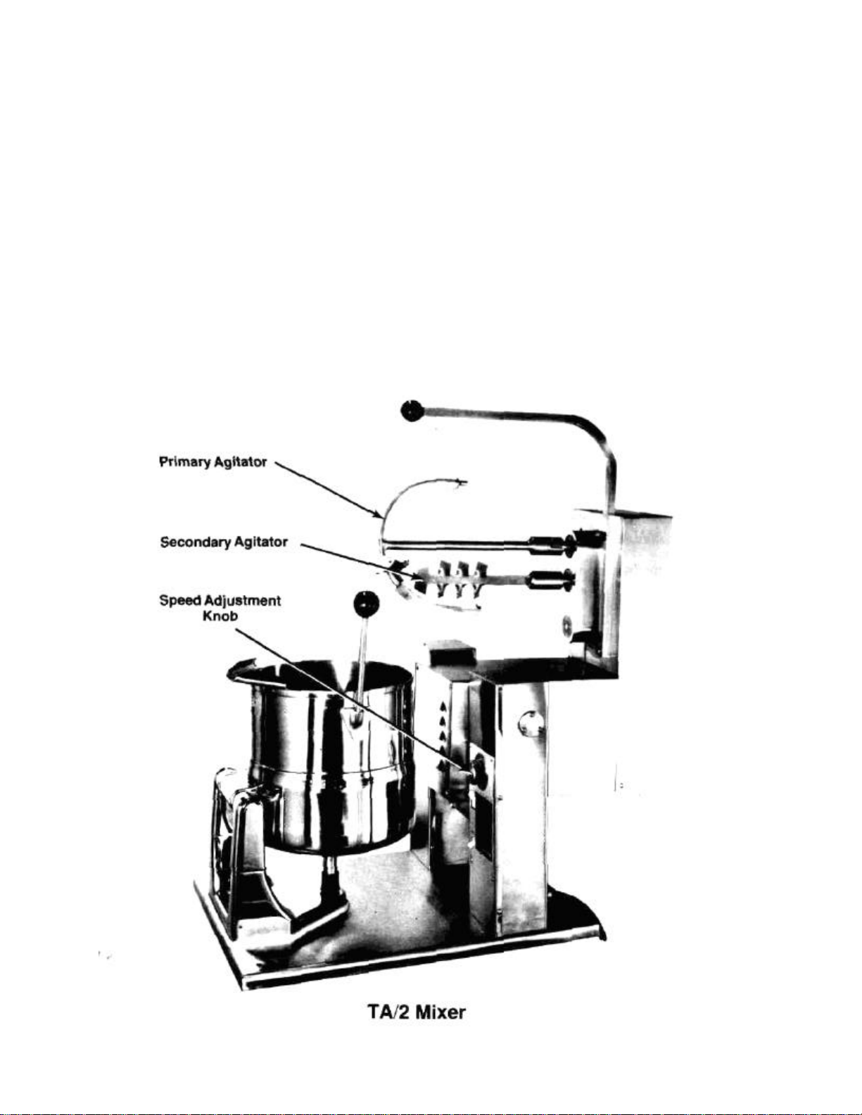
Model TA/2 has a motor (1/2 HP or optional 3/4 HP) that drives removable agitators through a combination of belt and gears. Th»stainless steel agitators consist of a primary agitator, which continuously scrapes the bottom and side of the kettle with nylon fingers, and a faster, counter rotating,
secondary agitator, which operates between the center line and the wall of the kettle.
Controls for the mixer are an on/off power switch and a variable speed adjustment knob. For safety,
the mixer is also equipped with an automatic tilt cutoff switch. All controls and drive components are
enclosed in a stainless steel console with a No. 4 finish.
Installation of the TA/2 requires connection to a 120 or 240 V, 1 PH, 50 or 60 HZ electrical service.
If the mixer is employed with an electrically heated kettle, a separate electrical connection is
required for the kettle heating elements.
For a description of the kettle component of your cooker/mixer, see the separate kettle manual.
2
Page 5

Installation & Start-Up
A. INSTALLATION
Your Groen mixer has been test operated at the factory and furnished with all internal wiring, complete
and ready for final connection. A wiring diagram is furnished on the inside of the service panel.
WARNING: INSTALLATION OF THE COOKER/MIXER MUST BE DONE BY PERSONNEL
QUALIFIED TO WORK WITH ELECTRICITY. IMPROPER INSTALLATION CAN
RESULT IN INJURY TO PERSONNEL AND/OR DAMAGE TO EQUIPMENT.
WARNING: ANY MECHANICAL OR ELECTRICAL CHANGE MUST BE APPROVED BY
THE GROEN FOOD SERVICE ENGINEERING DEPARTMENT.
1. Set the cooker/mixer in place and level it. Confirm that there is enough rear wall and overhead
clearance to tilt the mixer safely through its entire tilting range. Provide enough clearance to permit
access for service. Fasten the unit base to the work surface to eliminate any chance that the unit
could tip over.
2. Provide the proper electric power supply as specified on the electrical information plate attached to the
equipment. Observe local codes and/or The National Electrical Code in accordance with ANSI/NFPA
70 - latest edition. The installation should conform to the code that has the more strict requirements.
A standard mixer requires 1 PH, 60 HZ service that provides 8 AMP at 120 V. (See the table of
electrical requirements.) Any electrical service for the kettle requires a separate connection.
ELECTRICAL REQUIREMENTS
120 Volts 240 Volts
1/2 HP motor 7.9 Amps 4.0 Amps
3/4 HP motor 11.5 Amps 5.8 Amps
3. Bring electrical service through the entrance in the back of the control console. Use
waterproof conduit and waterproof connectors.
WARNING: TO PREVENT POSSIBLE ELECTRIC SHOCK, GROUND THE UNIT AT
THE TERMINAL PROVIDED.
4. The following check list may be used to confirm the correctness of the installation.
— Unit level
— Adequate clearance for tilting
— Access for service
— Unit fastened down
— Mixer power supply conforms to information plate and code
— Electrical conduit and connections are waterproof
— Mixer grounded
For instructions on installing the kettle component of your cooker/mixer, see the separate
kettle manual.
B. START-UP
After the mixer is installed, the installer should confirm that the equipment is operating correctly.
1. At the circuit breaker or fuse box, turn on the electric power supply to the mixer.
2. Tilt the mixer to confirm that it can swing back far enough, so there is no interference when
the kettle is tilted.
3. Make sure that each agitator is properly seated on its drive shaft and that the drive pin is
fully engaged with the coupling.
3
Page 6
Installation & Start-Up (con't)
4. Carefully examine the primary agitator to make sure that every nylon finger is positioned so
the flat side will be against the kettle wall and the beveled side will face the center of the
kettle. An inverted finger will not sweep the surface of the kettle and may be damaged or
knocked off the agitator.
5. When the mixer is in operating position, the primary agitator should be centered in the kettle,
and all the nylon fingers should touch the inside of the kettle.
6. Press the power switch to turn on the drive. Rotate the speed adjustment knob to confirm that
the mixer operates smoothly throughout its speed range.
7. Make sure the primary agitator turns in the correct direction, so it pushes the fingers ahead of
the agitator bar.
If the mixer functions as described above, it is ready for use. If it does not, contact your
authorized Groen Service Agency.
For instructions on initial start-up of the kettle component of your cooker/mixer, see the separate
kettle manual.
Operation
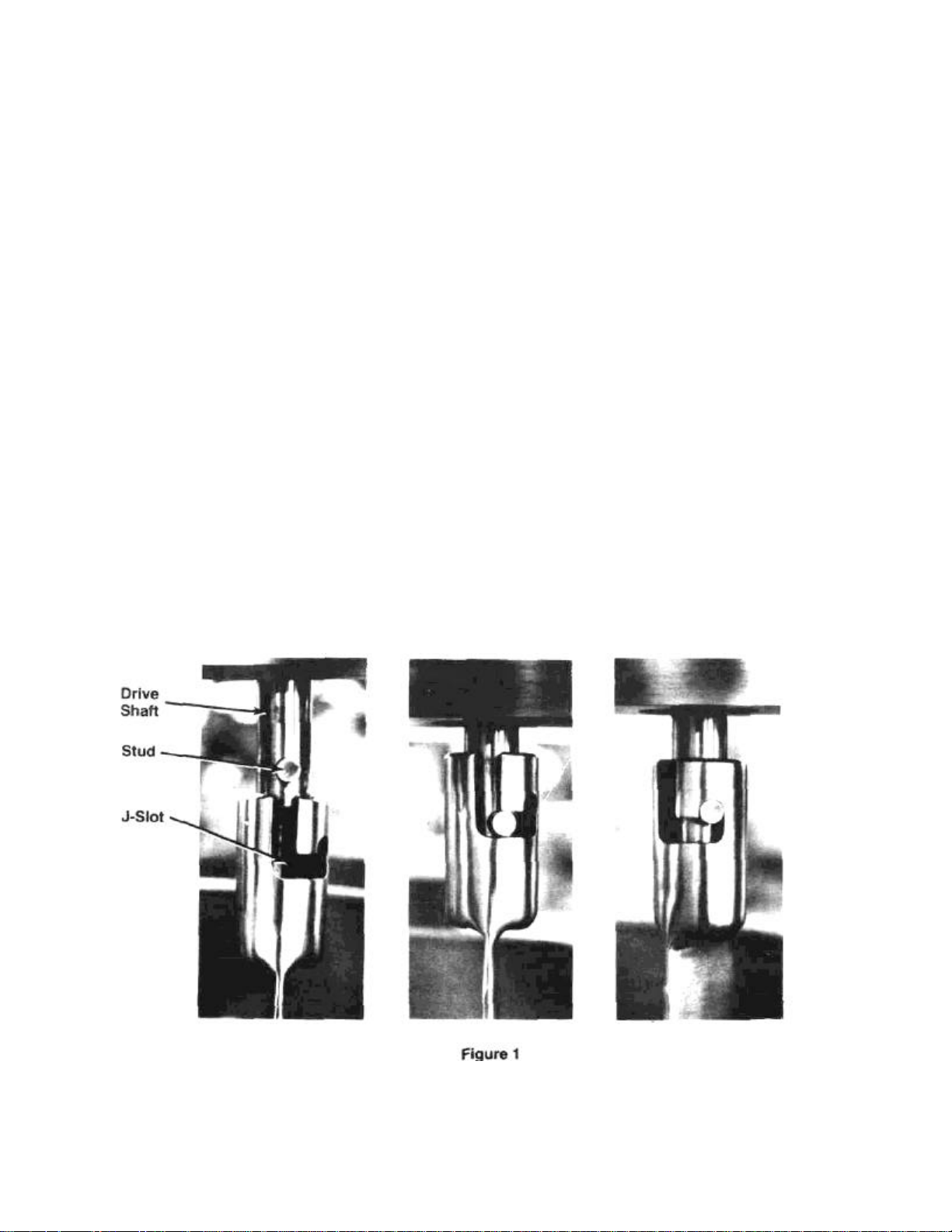
1. Mount the larger (primary) agitator on the drive shaft that operates over the center of the kettle
and the smaller (secondary) agitator on the other shaft. Slide the agitator up onto the shaft as
far as it will go, then turn the agitator and pull it down, so the stud on the shaft becomes firmly
seated against the end of the the J-slot. (See Figure 1)
2. Before you operate the mixer, confirm that each agitator is properly connected with its shaft. This
precaution will prevent damage to the unit.
4
Page 7

3. Turn the speed adjustment knob to the lowest setting. (See Figure 2) *
CAUTION: Starting with the mixer set at HIGH
SPEED MAY CAUSE material to
SPILL out of the kettle.
4. To start the mixer, press the power switch to "ON".
WARNING: IF POWER IS ON WHEN A TILTED
MIXER IS LOWERED INTO OPERATING POSITION, THE MIXER WILL
START AUTOMATICALLY, BECAUSE THE UNIT HAS AN
AUTOMATIC TILT CUTOFF SWITCH.
5. Set the desired mixing speed by turning the speed
adjustment knob. To avoid damaging the speed
control, do not run the mixer continuously under
heavy load at speeds less than 5% of full speed.
6. To stop the mixer, press the power switch to
"OFF".
7. Before you tilt the mixer, switch it off. As you begin
to tilt the mixer, tilt the kettle forward slightly, so
the agitators will clear the wall of the kettle. Scrape
excess product off the agitators, so it will not drip
onto the exterior of the kettle and surroundings.
8. When the cooker/mixer is to be cleaned or
serviced, or when it will not be used for a week or
longer, shut off all supplies of electric power to the
unit.
For instructions on operating the kettle component of
your cooker/mixer, see the separate kettle manual.
5
Page 8

Cleaning
A. SUGGESTED TOOLS & MATERIALS
1. Cleaner, like HC-10 or HC-32 from ECOLAB, Inc.
2. Stiff brush
3. Sanitizer, like Klenzade XY-12 B. PRECAUTIONS
WARNING: BEFORE CLEANING ANY PART OF THE MIXER, OTHER THAN THE
AGITATORS, SHUT OFF ALL ELECTRIC POWER TO THE COOKER/MIXER
AT THE CIRCUIT BREAKER OR FUSE BOX, TO AVOID POSSIBLE ELECTRIC SHOCK.
WARNING: KEEP WATER AND SOLUTIONS OUT OF THE CONTROLS, ELECTRICAL
WIRING, AND DRIVE MECHANISM. NEVER SPRAY OR HOSE THE MIXER.
C. PROCEDURE
1. Wash the agitators as soon as possible after use. If the unit is in continuous use, thoroughly clean all
parts of the mixer at least once every 12 hours.
2. Take each agitator off its drive shaft by pushing the agitator up toward the drive housing, then turning
the agitator and pulling it down, to slip the J-slot off the stud on the shaft. Remove the nylon fingers
from the primary agitator by sliding them to the end of the agitator bar and turning them until they can
slip off the end.
WARNING: AVOID CONTACT WITH THE CLEANER, AS RECOMMENDED BY THE
SUPPLIER. CAREFULLY READ THE WARNINGS AND FOLLOW THE
DIRECTIONS ON THE LABEL OF THE CLEANER. MANY CLEANERS ARE
HARMFUL TO THE SKIN, EYES, MUCOUS MEMBRANES, AND CLOTHING.
3. Prepare a hot solution of the cleaning compound as instructed by the supplier. Wash the agitator parts
and rinse them well.
NOTE: To obtain the sweeping action and avoid damage, make sure each nylon finger is replaced on
Use a cloth moistened with the cleaning solution to clean other parts of the mixer.
4. To remove materials stuck to the agitators, use a brush, sponge, cloth, plastic or rubber scraper, or
plastic wool along with the cleaning solution. To make washing easier, let the cleaning solution soak
into the residue. When you clean the stainless steel parts, do not use any abrasive material (like
metal sponges or scouring powder) or metal implement (like a spoon, scraper, or wire brush) that
might scratch the surface. Scratches make the surface hard to clean and provide places for bacteria
to grow. Do not use steel wool, which may leave particles imbedded in the surface and cause
eventual corrosion and pitting.
5. As part of the daily cleaning program, clean all surfaces that may have been soiled. Remember to
check such parts as the back and underside of the drive housing, back of the control console, etc.
6. When the agitators need to be sanitized, use a sanitizing solution equivalent to one that supplies 100
parts per million available chlorine. Obtain advice on the best sanitizing agent from your supplier of
sanitation products. Following the supplier's directions, apply the sanitizer after the agitators have
been washed, then rinse off the sanitizer completely. It is recommended that the agitators be sanitized
just before use.
CAUTION: NEVER LEAVE A SANITIZER in contact with the surface of stainless steel
7. The exterior of the unit may be polished with a recognized stainless steel cleaner like "Zepper" from
Zep Manufacturing Company.
Cleaning procedures for the kettle component of your cooker/mixer are described in the separate kettle
manual.
the agitator with the flat side against the kettle wall and the beveled side toward the center of
the kettle.
LONGER THAN 30 MINUTES. Longer contact can cause corrosion.
6
Page 9

OPERATOR'S
Troubleshooting List
The mixer is designed to operate smoothly and efficiently if properly maintained. However, the following is a
list of checks to make in the event of a problem.
If following the directions in this list does not correct the problem, call an authorized Groen Service Agency.
SYMPTOM
Motor will not run. a. That power is turned on at the circuit breaker or
Motor runs at low speed only. a. For a mechanical overload.
Motor speed varies rapidly. a. For an oscillating load, by disconnecting the mixer
Motor overheats and/or sparks excessively. a. For an overload.
Fuse blows frequently. a. For an overload.
Troubleshooting guidance for the kettle component of your cooker/mixer is contained in the separate kettle
manual.
WHAT TO CHECK
fuse box.
b. That power is being supplied to the building.
c. Fuse in the control console.
d. For a mechanical overload, that is, too much
material in the kettle or material that is too thick or
hard to mix.
drive from the agitators and checking motor
speed.
7
Page 10

Service
WARNING: USE OF ANY REPLACEMENT PARTS OTHER THAN THOSE SUPPLIED BY GROEN OR
A. PERIODIC SERVICE
1. The interior of control and drive housings should be kept clean and dry.
2. Electrical wiring should be kept securely connected and in good condition.
3. Regular service of the mixer should include cleaning the motor, checking the motor brushes and
commutator, lubricating the gears and pivot points, and checking the belt for tightness and wear.
B.COMPONENT REPLACEMENT
WARNING: BEFORE REPLACING ANY PARTS, SHUT OFF ALL ELECTRIC POWER SUPPLIES TO
All internal wiring is marked as shown on the schematic drawings. Be sure that new components are wired
in the same manner as the old components.
C. SERVICE RECORDS
A Service Log is provided with the warranty information. Each time service is performed on this Groen
equipment, enter the date on which the work was done, what was done, and who did it. The owner
should file the log with the warranty.
Service procedures for the kettle component of the cooker/mixer are described in the separate kettle
manual.
THEIR AUTHORIZED DISTRIBUTOR VOIDS ALL WARRANTIES AND CAN CAUSE
BODILY INJURY TO THE OPERATOR AND DAMAGE TO THE EQUIPMENT.
SERVICE PERFORMED BY OTHER THAN FACTORY AUTHORIZED PERSONNEL WILL
VOID ALL WARRANTIES.
THE COOKER/MIXER.
Service Troubleshooting
If an item in the "WHAT TO CHECK" column is followed by an asterisk (*), the work should be
done only by an authorized Groen Service Representative.
SYMPTOM WHAT TO CHECK
Motor will not run. a. Power supply to the unit.
Motor runs at high speed only a. Speed adjustment pot or wiring.*
without control. b. Power module.*
b.
Fuse in the control console.
c. For a mechanical overload.
d. That the tilt switch is closed.*
e. For a ground or short in the motor.*
f. For a defect in the power module. Check SCRs
and diodes.*
g.
Regulator.*
h. For loss of reference voltage. Check speed ad-
justment pot and wiring. Check maximum speed
pot.*
i. Motor brushes for wear or sticking.*
c. Regulator.*
8
Page 11

SYMPTOM
Motor runs at low speed only
a.
For a mechanical overload.
c. I.R. drop compensation, and adjust if set
too high.*
Motor overheats and/or
a.
For an overload.
Fuse blows frequently.
a.
For an overload.
cessive starting load.*
WHAT TO CHECK
Motor speed varies rapidly. a. For an oscillating load, by disconnecting the mixer
sparks excessively. b. Motor brushes for wear or improper seating.*
SCRs or diodes have short lives. a. For constant overload, peak overload, or ex-
b. Speed adjustment pot or wiring.*
c. Motor brushes for wear or improper seating.*
d. Regulator.*
e. For open motor field circuit, by checking field
current.*
drive from the agitators and checking motor speed.
b. Motor brushes for wear, improper seating, or
sticking in holders.*
d. SCRs.*
e. I.R. drop compensation pot.*
f. Dirty or defective regulator.*
g. Control panel and motor for a ground.*
c. Grade of brushes used.*
b. For incorrect jumper horsepower.*
c. Power module.*
d. Regulator.*
e. Whether line voltage is too high.*
f. Motor armature and wiring for ground or short.*
g. For open motor field circuit, by checking field
current.*
Troubleshooting guidance for the kettle component of your cooker/mixer is contained in the separate kettle
manual.
b. Panel for overheating, because ambient
temperature is too high or ventilation is
obstructed.*
c. Line voltage.*
d. Motor or wiring for a ground.*
9
Page 12

Parts List
NO.
To order parts, contact your authorized Groen Service Agency. Supply the model designation, part description, part
number, quantity, and where applicable, voltage and phase.
WARNING: USE ONLY GROEN SUPPLIED PARTS. SUBSTITUTION OF UNAUTHORIZED PARTS OR GENERIC
PARTS CAN CAUSE BODILY INJURY TO THE OPERATOR AND DAMAGE TO THE EQUIPMENT.
PAR
ITEM
T
NO.
1 12692
2 12691
3 13355
4 13382
5 9442
6 9199
7 6495
8 6455
9 13972
10 13491
11 12337
12 13357
13 13358
14 13378
15 13366
DESCRIPTION
TOLERANCE RING (PART OF ITEM 2)
PLASTIC KNOB (FRICTION)
GASKET (BUNA N RUBBER)
SHAFT
BRONZE BEARING
CORD GRIP
3-WIRE POWER CORD, 8' LONG
3-PRONG ELECTRIC CORD PLUG
CONTROL. DC ADJUSTABLE SPEED
MOTOR
SCRAPER, HALF FINGER
GEAR CARRIER
BEARING
PRIMARY SHAFT
SEAL
ITEM
NO.
PART
NO.
16 13383
17 13359
18 13386
19
20 13379
21 13360
22 13361
23 13384
24 13362
25 13363
26 13364
27 13380
28 13381
29 13385
30
DESCRIPTION
SPACER
GEAR, 48-TOOTH. 4.000 P. DIA.
KEY
1538
SNAPPING
SECONDARY SHAFT
GEAR, 18-TOOTH, 1.5000 P. DIA
GEAR, 72-TOOTH, 6.000 P. DIA,
SPACER
PULLEY, 7" O.D.
V-BELT
PULLEY, 2 3/4" O.D.
PULLEY SHAFT
PLUG
SPACER
9253
COUPLING PIN
A list of parts for the kettle component of your cooker/mixer is contained in the separate kettle manual.
References
KLENZADE SALES CENTER — ECOLAB, INC.
370 Wabasha
St. Paul, Minnesota 55102
800/328-3663 or 612/293-2233
NATIONAL FIRE PROTECTION ASSOCIATION
60 Battery March Park
Quincy, Massachusetts 02269
NFPA/70 The National Electrical Code
NATIONAL SANITATION FOUNDATION
3475 Plymouth Rd.
Ann Arbor, Michigan 48106
ZEP MANUFACTURING CO.
1390 Lunt Avenue
Elk Grove Village, Illinois 60007
KLENZADE SALES CENTER — ECOLAB, INC.
370 Wabasha
St. Paul, Minnesota 55102
800/328-3663 or 612/293-2233
10
Page 13

11
Page 14

Schematic
12
Page 15

LIMITED WARRANTY TO
OM
-
TA/2 (Revised
2/88)
COMMERCIAL PURCHASERS
(Continental U.S., Hawaii & Canadian Sales Only)
Groen Foodservice Equipment ("Groen Equipment") has been skillfully manufactured, carefully inspected and
packaged to meet rigid standards of excellence. Groen warrants its Equipment to be free from defects in
material and workmanship for (12) twelve months, with the following conditions and subject to the following
limitations.
I. This parts and labor warranty is limited to Groen Equipment sold to the original commercial
purchaser/users (but not original equipment manufacturers), at its original place of installation, in the
continental United States, Hawaii and Canada,
II. Damage during shipment is to be reported to the carrier, is not covered under this warranty, and is the
sole responsibility of purchaser/user.
III. Groen, or an authorized service representative, will repair or replace, at Groen's sole election, any
Groen Equipment, including but not limited to, draw-off valves, safety valves, gas and electric
components, found to be defective during the warranty period. As to warranty service in the territory
described above, Groen will absorb labor and portal to portal transportation costs (time & mileage) for
the first twelve (12) months from date of installation or fifteen (15) months from date of shipment from
Groen.
IV. This warranty does not cover boiler maintenance, calibration, periodic adjustments as specified in
V. THIS WARRANTY IS EXCLUSIVE AND IS IN LIEU OF ALL OTHER WARRANTIES, EXPRESSED
VI. Groen Equipment is for commercial use only. If sold as a component of another (O.E.M.)
operating instructions or manuals, and consumable parts such as scraper blades, gaskets, packing,
etc., or labor costs incurred for removal of adjacent equipment or objects to gain access to Groen
Equipment. This warranty does not cover defects caused by improper installation, abuse, careless
operation, or improper maintenance of equipment. This warranty does not cover damage caused by
poor water quality or improper boiler maintenance.
OR IMPLIED, INCLUDING ANY IMPLIED WARRANTY OF MERCHANT ABILITY OR FITNESS
FOR A PARTICULAR PURPOSE. EACH OF WHICH IS HEREBY EXPRESSLY DISCLAIMED. THE
REMEDIES DESCRIBED ABOVE ARE EXCLUSIVE AND IN NO EVENT SHALL GROEN BE
LIABLE FOR SPECIAL, CONSEQUENTIAL OR INCIDENTAL DAMAGES FOR THE BREACH OR
DELAY IN PERFORMANCE OF THIS WARRANTY.
manufacturer's equipment, or if used as a consumer product, such Equipment is sold AS IS and
without any warranty.
•(Covers All Foodservice Equipment Ordered after October 1, 1995)
GROEN, A Dover Industries
Company
1900 Pratt Boulevard Elk Grove
Village, Illinois 60007
Telephone: (312) 439-2400
TELEX 28 7413
 Loading...