

Page 1

Kayak HD
DIGITAL PRODUCTION SWITCHER
Installation and Service Manual
Software Version 6.9.4
071844808
MAY 2011
Page 2

CERTIFICATE
Certificate Number: 510040.001
The Quality System of:
Grass Valley USA, LLC and its Grass Valley Affiliates
Headquarters:
400 Providence Mine Road
Nevada City, CA 95945
United States
15655 SW Greystone Ct.
Beaverton, OR 97006
United States
Brunnenweg 9
D-64331 Weiterstadt
Germany
Kapittelweg 10
4827 HG Breda
The Nederlands
2300 So. Decker Lake Blvd.
Salt Lake City, UT 84119
United States
Including its implementation, meets the requirements of the standard:
ISO 9001:2008
Scope:
The design, manufacture and support of video and audio hardware and software products and related
systems.
This Certificate is valid until: June 14, 2012
This Certificate is valid as of: December 23, 2010
Certified for the first time: June 14, 2000
H. Pierre Sallé
President
KEMA-Registered Quality
The method of operation for quality certification is defined in the KEMA General Terms And Conditions For
Quality And Environmental Management Systems Certifications. Integral publication of this certificate is allowed.
KEMA-Registered Quality, Inc.
4377 County Line Road
Chalfont, PA 18914
Ph: (215)997-4519
Fax: (215)997-3809
CRT 001 042108
ccredited By:
ANAB
A
Page 3

Kayak HD
DIGITAL PRODUCTION SWITCHER
Installation and Service Manual
Software Version 6.9.4
071844808
MAY 2011
Page 4
Contacting Grass Valley
International
Support Centers
Local Support
Centers
(available
during normal
business hours)
France
24 x 7
Australia and New Zealand: +61 1300 721 495 Central/South America: +55 11 5509 3443
Middle East: +971 4 299 64 40 Near East and Africa: +800 8080 2020 or +33 1 48 25 20 20
Europe
+800 8080 2020 or +33 1 48 25 20 20
Hong Kong, Taiwan, Korea, Macau: +852 2531 3058 Indian Subcontinent: +91 22 24933476
Asia
Southeast Asia/Malaysia: +603 7805 3884 Southeast Asia/Singapore: +65 6379 1313
China: +861 0660 159 450 Japan: +81 3 5484 6868
Belarus, Russia, Tadzikistan, Ukraine, Uzbekistan: +7 095 2580924 225 Switzerland: +41 1 487 80 02
S. Europe/Italy-Roma: +39 06 87 20 35 28 -Milan: +39 02 48 41 46 58 S. Europe/Spain: +34 91 512 03 50
Benelux/Belgium: +32 (0) 2 334 90 30 Benelux/Netherlands: +31 (0) 35 62 38 42 1 N. Europe: +45 45 96 88 70
Germany, Austria, Eastern Europe: +49 6150 104 444 UK, Ireland, Israel: +44 118 923 0499
Copyright © Grass Valley USA, LLC. All rights reserved.
This product may be covered by one or more U.S. and foreign patents.
United States/Canada
24 x 7
+1 800 547 8949 or +1 530 478 4148
Grass Valley Web Site
The www.grassvalley.com web site offers the following:
Online User Documentation — Current versions of product catalogs, brochures,
data sheets, ordering guides, planning guides, manuals, and release notes
in .pdf format can be downloaded.
FAQ Database — Solutions to problems and troubleshooting efforts can be
found by searching our Frequently Asked Questions (FAQ) database.
Software Downloads — Download software updates, drivers, and patches.
4 Kayak HD — Installation and Service Manual
Page 5

Contents
Preface. . . . . . . . . . . . . . . . . . . . . . . . . . . . . . . . . . . . . . . . . . . . . . . . . . . . . . . . . . . . . . . . . . . . 11
Regulatory Notices
Safety Summary
Contents
About This Manual . . . . . . . . . . . . . . . . . . . . . . . . . . . . . . . . . . . . . . . . . . . . . . . . . . . . 11
Standard Documentation Set. . . . . . . . . . . . . . . . . . . . . . . . . . . . . . . . . . . . . . . . . . 11
Other Documentation . . . . . . . . . . . . . . . . . . . . . . . . . . . . . . . . . . . . . . . . . . . . . . . . 11
Certifications and Compliances . . . . . . . . . . . . . . . . . . . . . . . . . . . . . . . . . . . . . . . . . 13
FCC Emission Control . . . . . . . . . . . . . . . . . . . . . . . . . . . . . . . . . . . . . . . . . . . . . . . 13
Canadian EMC Notice of Compliance . . . . . . . . . . . . . . . . . . . . . . . . . . . . . . . . . . 13
EN55022 Class A Warning . . . . . . . . . . . . . . . . . . . . . . . . . . . . . . . . . . . . . . . . . . . . 13
Canadian Certified Power Cords . . . . . . . . . . . . . . . . . . . . . . . . . . . . . . . . . . . . . . 14
Canadian Certified AC Adapter . . . . . . . . . . . . . . . . . . . . . . . . . . . . . . . . . . . . . . . 14
FCC Emission Limits . . . . . . . . . . . . . . . . . . . . . . . . . . . . . . . . . . . . . . . . . . . . . . . 14
Certification . . . . . . . . . . . . . . . . . . . . . . . . . . . . . . . . . . . . . . . . . . . . . . . . . . . . . . 14
Safety Terms and Symbols. . . . . . . . . . . . . . . . . . . . . . . . . . . . . . . . . . . . . . . . . . . . . . 17
Terms in This Manual . . . . . . . . . . . . . . . . . . . . . . . . . . . . . . . . . . . . . . . . . . . . . . . . 17
Terms on the Product . . . . . . . . . . . . . . . . . . . . . . . . . . . . . . . . . . . . . . . . . . . . . . . . 17
Symbols on the Product . . . . . . . . . . . . . . . . . . . . . . . . . . . . . . . . . . . . . . . . . . . . . . 18
Warnings . . . . . . . . . . . . . . . . . . . . . . . . . . . . . . . . . . . . . . . . . . . . . . . . . . . . . . . . . . . . 18
Cautions . . . . . . . . . . . . . . . . . . . . . . . . . . . . . . . . . . . . . . . . . . . . . . . . . . . . . . . . . . . . . 19
Section 1 — System Overview. . . . . . . . . . . . . . . . . . . . . . . . . . . . . . . . . . . . . . . . . . 21
Introduction . . . . . . . . . . . . . . . . . . . . . . . . . . . . . . . . . . . . . . . . . . . . . . . . . . . . . . . . . . 21
Kayak HD or SD Switcher Models . . . . . . . . . . . . . . . . . . . . . . . . . . . . . . . . . . . . . 21
Kayak HD Standard Features . . . . . . . . . . . . . . . . . . . . . . . . . . . . . . . . . . . . . . . . . 22
Kayak HD Options . . . . . . . . . . . . . . . . . . . . . . . . . . . . . . . . . . . . . . . . . . . . . . . . . . 24
Supported Control Protocols . . . . . . . . . . . . . . . . . . . . . . . . . . . . . . . . . . . . . . . . . . 25
System Components . . . . . . . . . . . . . . . . . . . . . . . . . . . . . . . . . . . . . . . . . . . . . . . . . . . 26
Kayak HD Control Surfaces. . . . . . . . . . . . . . . . . . . . . . . . . . . . . . . . . . . . . . . . . . . 26
1 M/E Control Panel . . . . . . . . . . . . . . . . . . . . . . . . . . . . . . . . . . . . . . . . . . . . . . . 26
1.5 and 2 M/E Control Panel . . . . . . . . . . . . . . . . . . . . . . . . . . . . . . . . . . . . . . . . 27
2.5 and 3M/E Control Panel. . . . . . . . . . . . . . . . . . . . . . . . . . . . . . . . . . . . . . . . . 28
Kayak HD Video Processor Frames . . . . . . . . . . . . . . . . . . . . . . . . . . . . . . . . . . . . 29
Kayak 4 RU Frame . . . . . . . . . . . . . . . . . . . . . . . . . . . . . . . . . . . . . . . . . . . . . . . . . 29
Kayak 8 RU Frame . . . . . . . . . . . . . . . . . . . . . . . . . . . . . . . . . . . . . . . . . . . . . . . . . 30
KDD-PSU Power Supply Option . . . . . . . . . . . . . . . . . . . . . . . . . . . . . . . . . . . . . . 31
Video Signal Flow . . . . . . . . . . . . . . . . . . . . . . . . . . . . . . . . . . . . . . . . . . . . . . . . . . . . . 32
Section 2 — Installation. . . . . . . . . . . . . . . . . . . . . . . . . . . . . . . . . . . . . . . . . . . . . . . . . 35
Pre-Installation Procedures . . . . . . . . . . . . . . . . . . . . . . . . . . . . . . . . . . . . . . . . . . . . . 35
System Survey . . . . . . . . . . . . . . . . . . . . . . . . . . . . . . . . . . . . . . . . . . . . . . . . . . . . . . 35
Line Voltage . . . . . . . . . . . . . . . . . . . . . . . . . . . . . . . . . . . . . . . . . . . . . . . . . . . . . . . . 35
Required Tools . . . . . . . . . . . . . . . . . . . . . . . . . . . . . . . . . . . . . . . . . . . . . . . . . . . . . . 35
Safety Requirements . . . . . . . . . . . . . . . . . . . . . . . . . . . . . . . . . . . . . . . . . . . . . . . . . . . 36
Installation Tasks. . . . . . . . . . . . . . . . . . . . . . . . . . . . . . . . . . . . . . . . . . . . . . . . . . . . . . 36
Kayak HD — Installation and Service Manual 5
Page 6

Contents
General Rack Mounting Instructions . . . . . . . . . . . . . . . . . . . . . . . . . . . . . . . . . . . . 37
4 RU Frame . . . . . . . . . . . . . . . . . . . . . . . . . . . . . . . . . . . . . . . . . . . . . . . . . . . . . . . . . . 37
Video Processor Frame Installation . . . . . . . . . . . . . . . . . . . . . . . . . . . . . . . . . . . . 37
4 RU Compact Frame Dimensions . . . . . . . . . . . . . . . . . . . . . . . . . . . . . . . . . . . 37
4 RU Compact Frame Rack Mounting. . . . . . . . . . . . . . . . . . . . . . . . . . . . . . . . . . 39
Kayak HD Video Processor 4 RU Frame. . . . . . . . . . . . . . . . . . . . . . . . . . . . . . . . 40
License EEPROMs. . . . . . . . . . . . . . . . . . . . . . . . . . . . . . . . . . . . . . . . . . . . . . . . . 41
8 RU Frame . . . . . . . . . . . . . . . . . . . . . . . . . . . . . . . . . . . . . . . . . . . . . . . . . . . . . . . . . . 42
Video Processor Frame Installation . . . . . . . . . . . . . . . . . . . . . . . . . . . . . . . . . . . . 42
8 RU Frame Dimensions. . . . . . . . . . . . . . . . . . . . . . . . . . . . . . . . . . . . . . . . . . . . 42
8 RU Frame Rack Mounting . . . . . . . . . . . . . . . . . . . . . . . . . . . . . . . . . . . . . . . . . . 44
Kayak HD Frame Connectors. . . . . . . . . . . . . . . . . . . . . . . . . . . . . . . . . . . . . . . . . . . 47
Internal Redundant Power Supply Option . . . . . . . . . . . . . . . . . . . . . . . . . . . . . . . 48
Removing and Replacing the Kayak HD Frame Door . . . . . . . . . . . . . . . . . . . . . . 48
Control Panel Installation . . . . . . . . . . . . . . . . . . . . . . . . . . . . . . . . . . . . . . . . . . . . . . 50
1 M/E Control Panel . . . . . . . . . . . . . . . . . . . . . . . . . . . . . . . . . . . . . . . . . . . . . . . . 50
2 M/E Control Panel . . . . . . . . . . . . . . . . . . . . . . . . . . . . . . . . . . . . . . . . . . . . . . . . 52
3M/E Control Panel . . . . . . . . . . . . . . . . . . . . . . . . . . . . . . . . . . . . . . . . . . . . . . . . . 54
Panel Mounting Options . . . . . . . . . . . . . . . . . . . . . . . . . . . . . . . . . . . . . . . . . . . . . 55
Table Top Use . . . . . . . . . . . . . . . . . . . . . . . . . . . . . . . . . . . . . . . . . . . . . . . . . . . . 55
Surface Mount Cutout Dimensions . . . . . . . . . . . . . . . . . . . . . . . . . . . . . . . . . . 55
Securing Panels to Mounting Surface . . . . . . . . . . . . . . . . . . . . . . . . . . . . . . . . . . 56
Kayak HD Control Panel Connectors . . . . . . . . . . . . . . . . . . . . . . . . . . . . . . . . 57
KDD-PSU Power Supply Option . . . . . . . . . . . . . . . . . . . . . . . . . . . . . . . . . . . . . . 58
Pin Assignments. . . . . . . . . . . . . . . . . . . . . . . . . . . . . . . . . . . . . . . . . . . . . . . . . . . . . . 59
GPI / Tally Connections . . . . . . . . . . . . . . . . . . . . . . . . . . . . . . . . . . . . . . . . . . . . . . . 60
Kayak HD GPI and Tally Interface . . . . . . . . . . . . . . . . . . . . . . . . . . . . . . . . . . . . 61
GPI Inputs . . . . . . . . . . . . . . . . . . . . . . . . . . . . . . . . . . . . . . . . . . . . . . . . . . . . . . . . . 61
GPI Input Structure. . . . . . . . . . . . . . . . . . . . . . . . . . . . . . . . . . . . . . . . . . . . . . . . 62
GPI / Tally Outputs . . . . . . . . . . . . . . . . . . . . . . . . . . . . . . . . . . . . . . . . . . . . . . . . . 63
Cabling Overview . . . . . . . . . . . . . . . . . . . . . . . . . . . . . . . . . . . . . . . . . . . . . . . . . . . . 70
Control Cabling . . . . . . . . . . . . . . . . . . . . . . . . . . . . . . . . . . . . . . . . . . . . . . . . . . . . . . 70
Kayak HD 100C Control Cabling . . . . . . . . . . . . . . . . . . . . . . . . . . . . . . . . . . . . . . 70
Kayak HD 150C, 200C,and 200 Control Cabling . . . . . . . . . . . . . . . . . . . . . . . . . 71
Mouse Connection . . . . . . . . . . . . . . . . . . . . . . . . . . . . . . . . . . . . . . . . . . . . . . . . . . 71
Ethernet Switches and Hubs . . . . . . . . . . . . . . . . . . . . . . . . . . . . . . . . . . . . . . . . . . 71
Factory Network Settings . . . . . . . . . . . . . . . . . . . . . . . . . . . . . . . . . . . . . . . . . . . . 73
Video Cabling for all Kayak HD Switchers . . . . . . . . . . . . . . . . . . . . . . . . . . . . . . . 73
Inputs . . . . . . . . . . . . . . . . . . . . . . . . . . . . . . . . . . . . . . . . . . . . . . . . . . . . . . . . . . . . . 73
Outputs. . . . . . . . . . . . . . . . . . . . . . . . . . . . . . . . . . . . . . . . . . . . . . . . . . . . . . . . . . . . 74
Reference Input . . . . . . . . . . . . . . . . . . . . . . . . . . . . . . . . . . . . . . . . . . . . . . . . . . . . . 74
Kayak HD Video Timing. . . . . . . . . . . . . . . . . . . . . . . . . . . . . . . . . . . . . . . . . . . . . . . 74
Kayak HD Home - Install Menu. . . . . . . . . . . . . . . . . . . . . . . . . . . . . . . . . . . . . . . 74
Select the Video Standard . . . . . . . . . . . . . . . . . . . . . . . . . . . . . . . . . . . . . . . . . . . . 77
Select the Video Reference Source . . . . . . . . . . . . . . . . . . . . . . . . . . . . . . . . . . . . . 78
Select SF Mode . . . . . . . . . . . . . . . . . . . . . . . . . . . . . . . . . . . . . . . . . . . . . . . . . . . . . 80
Adjust Internal System Timing. . . . . . . . . . . . . . . . . . . . . . . . . . . . . . . . . . . . . . . . 81
Main Panel Adjustments . . . . . . . . . . . . . . . . . . . . . . . . . . . . . . . . . . . . . . . . . . . . . . . 85
Install - Calibration Menu . . . . . . . . . . . . . . . . . . . . . . . . . . . . . . . . . . . . . . . . . . . . 85
Fader Calibration. . . . . . . . . . . . . . . . . . . . . . . . . . . . . . . . . . . . . . . . . . . . . . . . . . 85
Joystick Calibration. . . . . . . . . . . . . . . . . . . . . . . . . . . . . . . . . . . . . . . . . . . . . . . . 86
Touch Screen Calibration. . . . . . . . . . . . . . . . . . . . . . . . . . . . . . . . . . . . . . . . . . . 86
Kayak System Control via PC . . . . . . . . . . . . . . . . . . . . . . . . . . . . . . . . . . . . . . . . . . 87
Connecting a PC / Laptop to a Kayak HD System . . . . . . . . . . . . . . . . . . . . . . . 87
6 Kayak HD — Installation and Service Manual
Page 7

Contents
Section 3 — Configuration . . . . . . . . . . . . . . . . . . . . . . . . . . . . . . . . . . . . . . . . . . . . . . 89
Introduction . . . . . . . . . . . . . . . . . . . . . . . . . . . . . . . . . . . . . . . . . . . . . . . . . . . . . . . . . . 89
Basic Configuration Steps . . . . . . . . . . . . . . . . . . . . . . . . . . . . . . . . . . . . . . . . . . . . . . 89
Setting Up IP Addresses. . . . . . . . . . . . . . . . . . . . . . . . . . . . . . . . . . . . . . . . . . . . . . . . 90
Network Settings . . . . . . . . . . . . . . . . . . . . . . . . . . . . . . . . . . . . . . . . . . . . . . . . . . . . 90
IP Address. . . . . . . . . . . . . . . . . . . . . . . . . . . . . . . . . . . . . . . . . . . . . . . . . . . . . . . . 90
Netmask . . . . . . . . . . . . . . . . . . . . . . . . . . . . . . . . . . . . . . . . . . . . . . . . . . . . . . . . . 92
Network Settings - Telnet. . . . . . . . . . . . . . . . . . . . . . . . . . . . . . . . . . . . . . . . . . . . . 92
Open a Telnet Connection . . . . . . . . . . . . . . . . . . . . . . . . . . . . . . . . . . . . . . . . . . 93
IP Address. . . . . . . . . . . . . . . . . . . . . . . . . . . . . . . . . . . . . . . . . . . . . . . . . . . . . . . . 94
Netmask . . . . . . . . . . . . . . . . . . . . . . . . . . . . . . . . . . . . . . . . . . . . . . . . . . . . . . . . . 94
Subnet Mask . . . . . . . . . . . . . . . . . . . . . . . . . . . . . . . . . . . . . . . . . . . . . . . . . . . . . . 94
Gateway. . . . . . . . . . . . . . . . . . . . . . . . . . . . . . . . . . . . . . . . . . . . . . . . . . . . . . . . . . 95
Software Installation. . . . . . . . . . . . . . . . . . . . . . . . . . . . . . . . . . . . . . . . . . . . . . . . . . . 96
Software Versions . . . . . . . . . . . . . . . . . . . . . . . . . . . . . . . . . . . . . . . . . . . . . . . . . . . 96
Software Update . . . . . . . . . . . . . . . . . . . . . . . . . . . . . . . . . . . . . . . . . . . . . . . . . . . . 96
Software Option Licenses . . . . . . . . . . . . . . . . . . . . . . . . . . . . . . . . . . . . . . . . . . . . . . 97
Available Options and Configuration Licenses . . . . . . . . . . . . . . . . . . . . . . . . . . 98
Installing Licenses . . . . . . . . . . . . . . . . . . . . . . . . . . . . . . . . . . . . . . . . . . . . . . . . . . . 99
Button Assignment (Source to Button Mapping). . . . . . . . . . . . . . . . . . . . . . . . . . . 99
Assign Sources . . . . . . . . . . . . . . . . . . . . . . . . . . . . . . . . . . . . . . . . . . . . . . . . . . . . . . 99
Rename Sources . . . . . . . . . . . . . . . . . . . . . . . . . . . . . . . . . . . . . . . . . . . . . . . . . . . . 102
Assigning Permanent Sources to AUX Buses . . . . . . . . . . . . . . . . . . . . . . . . . . . . . 105
Assigning On-Air Tallies . . . . . . . . . . . . . . . . . . . . . . . . . . . . . . . . . . . . . . . . . . . . . . 106
Save Installation and Configuration Settings . . . . . . . . . . . . . . . . . . . . . . . . . . . . . 107
Save All Install Data . . . . . . . . . . . . . . . . . . . . . . . . . . . . . . . . . . . . . . . . . . . . . . . . 108
Save Panel Install Data . . . . . . . . . . . . . . . . . . . . . . . . . . . . . . . . . . . . . . . . . . . . . . 109
Save Application Data . . . . . . . . . . . . . . . . . . . . . . . . . . . . . . . . . . . . . . . . . . . . . . 109
Panel Lock . . . . . . . . . . . . . . . . . . . . . . . . . . . . . . . . . . . . . . . . . . . . . . . . . . . . . . . . . . 110
Locking The Panel . . . . . . . . . . . . . . . . . . . . . . . . . . . . . . . . . . . . . . . . . . . . . . . . . . 110
Unlocking The Panel . . . . . . . . . . . . . . . . . . . . . . . . . . . . . . . . . . . . . . . . . . . . . . . . 112
Install Menus Reference . . . . . . . . . . . . . . . . . . . . . . . . . . . . . . . . . . . . . . . . . . . . . . . 113
Install - E-Box . . . . . . . . . . . . . . . . . . . . . . . . . . . . . . . . . . . . . . . . . . . . . . . . . . . . . . 113
Install - Genlock Menu . . . . . . . . . . . . . . . . . . . . . . . . . . . . . . . . . . . . . . . . . . . . 114
Selecting the Video Standard . . . . . . . . . . . . . . . . . . . . . . . . . . . . . . . . . . . . . . . 114
Selecting the Video Reference Source. . . . . . . . . . . . . . . . . . . . . . . . . . . . . . . . 116
Install - Editor Menu . . . . . . . . . . . . . . . . . . . . . . . . . . . . . . . . . . . . . . . . . . . . . . 117
Install - GPI Menu . . . . . . . . . . . . . . . . . . . . . . . . . . . . . . . . . . . . . . . . . . . . . . . . 120
Install - GPO Menu . . . . . . . . . . . . . . . . . . . . . . . . . . . . . . . . . . . . . . . . . . . . . . . 121
Install - Misc Menu . . . . . . . . . . . . . . . . . . . . . . . . . . . . . . . . . . . . . . . . . . . . . . . 122
Install - Machine Control Menu. . . . . . . . . . . . . . . . . . . . . . . . . . . . . . . . . . . . . 123
Install - VTR Emulation Menu . . . . . . . . . . . . . . . . . . . . . . . . . . . . . . . . . . . . . . 128
Install – EBox - AUX Menu. . . . . . . . . . . . . . . . . . . . . . . . . . . . . . . . . . . . . . . . . 130
Install - AUX CP Menu . . . . . . . . . . . . . . . . . . . . . . . . . . . . . . . . . . . . . . . . . . . . 131
Install – UMD Menu . . . . . . . . . . . . . . . . . . . . . . . . . . . . . . . . . . . . . . . . . . . . . . 132
Install - Router Menu. . . . . . . . . . . . . . . . . . . . . . . . . . . . . . . . . . . . . . . . . . . . . . 134
Install - Tally Menu . . . . . . . . . . . . . . . . . . . . . . . . . . . . . . . . . . . . . . . . . . . . . . . 142
System Setup Menu. . . . . . . . . . . . . . . . . . . . . . . . . . . . . . . . . . . . . . . . . . . . . . . . . 143
Device Control Menu . . . . . . . . . . . . . . . . . . . . . . . . . . . . . . . . . . . . . . . . . . . . . 144
Configure Device Menu . . . . . . . . . . . . . . . . . . . . . . . . . . . . . . . . . . . . . . . . . . . 145
Reset / Check / Clear Device Menu. . . . . . . . . . . . . . . . . . . . . . . . . . . . . . . . . 145
Kayak HD — Installation and Service Manual 7
Page 8

Contents
Section 4 — Maintenance . . . . . . . . . . . . . . . . . . . . . . . . . . . . . . . . . . . . . . . . . . . . . 147
Introduction. . . . . . . . . . . . . . . . . . . . . . . . . . . . . . . . . . . . . . . . . . . . . . . . . . . . . . . . . 147
Servicing Precautions. . . . . . . . . . . . . . . . . . . . . . . . . . . . . . . . . . . . . . . . . . . . . . . . . 147
Tools Required . . . . . . . . . . . . . . . . . . . . . . . . . . . . . . . . . . . . . . . . . . . . . . . . . . . . . . 147
Grass Valley Customer Service FAQ Database . . . . . . . . . . . . . . . . . . . . . . . . . . . 147
Grass Valley Web Site . . . . . . . . . . . . . . . . . . . . . . . . . . . . . . . . . . . . . . . . . . . . . . 148
Troubleshooting and Diagnostics . . . . . . . . . . . . . . . . . . . . . . . . . . . . . . . . . . . . . . 148
Diagnosis Menu . . . . . . . . . . . . . . . . . . . . . . . . . . . . . . . . . . . . . . . . . . . . . . . . . . . 148
NetCentral and SNMP Agents . . . . . . . . . . . . . . . . . . . . . . . . . . . . . . . . . . . . . 149
Manually Configure the SNMP Trap Destination . . . . . . . . . . . . . . . . . . . . . 150
Network Problems with Sidepanel . . . . . . . . . . . . . . . . . . . . . . . . . . . . . . . . . . . 151
Lost LAN Connection . . . . . . . . . . . . . . . . . . . . . . . . . . . . . . . . . . . . . . . . . . . . . . 153
Problems with Network Configuration. . . . . . . . . . . . . . . . . . . . . . . . . . . . . . . . 153
Running Panel Tests. . . . . . . . . . . . . . . . . . . . . . . . . . . . . . . . . . . . . . . . . . . . . . . . 154
Local Panel Test Mode 1 (Button Test): . . . . . . . . . . . . . . . . . . . . . . . . . . . . . . 155
Local Panel Test Mode 2 (LED Test): . . . . . . . . . . . . . . . . . . . . . . . . . . . . . . . . 155
Local Panel Test Mode 3 (Group Test / On Air Highlight Test):. . . . . . . . . 156
Local Panel Test Mode 4 (Connect Mode): . . . . . . . . . . . . . . . . . . . . . . . . . . . 156
Local Panel Test Mode 5 (Color Test): . . . . . . . . . . . . . . . . . . . . . . . . . . . . . . . 157
Version Mismatch Button Test . . . . . . . . . . . . . . . . . . . . . . . . . . . . . . . . . . . . . 158
Panel CPU Reset . . . . . . . . . . . . . . . . . . . . . . . . . . . . . . . . . . . . . . . . . . . . . . . . . . . 159
Fan Failure. . . . . . . . . . . . . . . . . . . . . . . . . . . . . . . . . . . . . . . . . . . . . . . . . . . . . . . . . . 160
HD RAM Recorder Field Upgrade Procedure. . . . . . . . . . . . . . . . . . . . . . . . . . . . 160
Field Upgrade Parts List . . . . . . . . . . . . . . . . . . . . . . . . . . . . . . . . . . . . . . . . . . 160
Installing HD RAM Recorder Upgrade . . . . . . . . . . . . . . . . . . . . . . . . . . . . . . 160
Control Processor Board Replacement . . . . . . . . . . . . . . . . . . . . . . . . . . . . . . . . . . 161
Lifetime of the Internal Battery . . . . . . . . . . . . . . . . . . . . . . . . . . . . . . . . . . . . . . . . 163
Changing the Batteries. . . . . . . . . . . . . . . . . . . . . . . . . . . . . . . . . . . . . . . . . . . . . . . . 163
Change the Kayak HD Frame Battery . . . . . . . . . . . . . . . . . . . . . . . . . . . . . . . . . 163
Change the Kayak HD Control Panel Battery . . . . . . . . . . . . . . . . . . . . . . . . . . 165
Additional Kayak Panel FRUs . . . . . . . . . . . . . . . . . . . . . . . . . . . . . . . . . . . . . . . . . 167
Removing the Top of the Control Panel Enclosure . . . . . . . . . . . . . . . . . . . . . . 168
Replacing Control Panel FRUs . . . . . . . . . . . . . . . . . . . . . . . . . . . . . . . . . . . . . . . 172
Replacing the Panel CPU Board (2-M/E and 3-M/E) . . . . . . . . . . . . . . . . . . 173
Replacing the Menu Display Board (2-M/E and 3-M/E) . . . . . . . . . . . . . . . 176
Replacing a Joystick (2-M/E and 3-M/E) . . . . . . . . . . . . . . . . . . . . . . . . . . . . 179
Replacing a Lever Arm (2-M/E and 3-M/E) . . . . . . . . . . . . . . . . . . . . . . . . . 181
Replacing a Ribbon Cable Harness (2-M/E and 3-M/E) . . . . . . . . . . . . . . . 183
Replacing CF Cards (2-M/E and 3-M/E) (128MB/512MB) . . . . . . . . . . . . . 185
2-M/E Only Control Panel FRUs . . . . . . . . . . . . . . . . . . . . . . . . . . . . . . . . . . . 186
Replacing a 2-M/E Control Panel Fan. . . . . . . . . . . . . . . . . . . . . . . . . . . . . . . 189
3-M/E Control Panel FRUs . . . . . . . . . . . . . . . . . . . . . . . . . . . . . . . . . . . . . . . . 190
Replacing a 3-M/E Control Panel Fan. . . . . . . . . . . . . . . . . . . . . . . . . . . . . . . 195
BIOS Settings . . . . . . . . . . . . . . . . . . . . . . . . . . . . . . . . . . . . . . . . . . . . . . . . . . . . . . 196
Frame BIOS Settings . . . . . . . . . . . . . . . . . . . . . . . . . . . . . . . . . . . . . . . . . . . . . . 196
Panel BIOS Settings. . . . . . . . . . . . . . . . . . . . . . . . . . . . . . . . . . . . . . . . . . . . . . . 197
Appendix A — Specifications. . . . . . . . . . . . . . . . . . . . . . . . . . . . . . . . . . . . . . . . . . 199
Kayak HD Systems. . . . . . . . . . . . . . . . . . . . . . . . . . . . . . . . . . . . . . . . . . . . . . . . . 199
8 Kayak HD — Installation and Service Manual
Page 9

Appendix B — Field Replaceable Units and RoHS Compliance. . . . . 203
Appendix C — Control Interfaces . . . . . . . . . . . . . . . . . . . . . . . . . . . . . . . . . . . . . . 205
Supported GVG100 Commands . . . . . . . . . . . . . . . . . . . . . . . . . . . . . . . . . . . . . . . . 205
Supported GVG200 Commands . . . . . . . . . . . . . . . . . . . . . . . . . . . . . . . . . . . . . . . . 207
ESAM Protocol . . . . . . . . . . . . . . . . . . . . . . . . . . . . . . . . . . . . . . . . . . . . . . . . . . . . . . 208
Supported Commands . . . . . . . . . . . . . . . . . . . . . . . . . . . . . . . . . . . . . . . . . . . . . . 208
ESAM Installation and Configuration . . . . . . . . . . . . . . . . . . . . . . . . . . . . . . . . . 209
Index . . . . . . . . . . . . . . . . . . . . . . . . . . . . . . . . . . . . . . . . . . . . . . . . . . . . . . . . . . . . . . . . . . . . . 211
Contents
Kayak HD — Installation and Service Manual 9
Page 10

Contents
10 Kayak HD — Installation and Service Manual
Page 11

Preface
About This Manual
This Kayak HD Installation and Service Manual provides installation, configuration, and service information for the Grass Valley Kayak HD Digital
Production Switcher. This manual is designed for technical personnel
responsible for installing and maintaining Kayak HD systems.
Standard Documentation Set
The standard Kayak HD documentation set consists of:
•User Manual
• Installation and Service Manual
• Release Notes
The User Manual contains background information about the Kayak HD
Digital Production switcher and describes operating procedures. This
manual can be used while learning about Kayak HD and for enhancing
your basic knowledge of the system.
The Installation and Service Manual contains information about installing,
configuring, and maintaining the system. The service section of this
manual is in preparation.
The Release Notes contain information about new features and system
enhancements for a specific software version, and also includes software
installation procedures. Always check the release notes for your current
system software before you begin operating your system.
Other Documentation
Communication protocols of Kayak HD are available upon request for
developers and software engineers to use to design editor and other
external interfaces to the Kayak HD system.
Kayak HD — Installation and Service Manual 11
Page 12

Preface
12 Kayak HD — Installation and Service Manual
Page 13

Regulatory Notices
Certifications and Compliances
FCC Emission Control
This equipment has been tested and found to comply with the limits for a
Class A digital device, pursuant to Part 15 of the FCC Rules. These limits
are designed to provide reasonable protection against harmful interference
when the equipment is operated in a commercial environment. This equip
ment generates, uses, and can radiate radio frequency energy and, if not
installed and used in accordance with the instruction manual, may cause
harmful interference to radio communications. Operation of this equip
ment in a residential area is likely to cause harmful interference in which
case the user will be required to correct the interference at his own expense.
Changes or modifications not expressly approved by Grass Valley Group
can affect emission compliance and could void the user’s authority to
operate this equipment.
-
-
Canadian EMC Notice of Compliance
This digital apparatus does not exceed the Class A limits for radio noise
emissions from digital apparatus set out in the Radio Interference Regula
tions of the Canadian Department of Communications.
Le présent appareil numérique n’emet pas de bruits radioélectriques
dépassant les limites applicables aux appareils numeriques de la classe A
préscrites dans le Règlement sur le brouillage radioélectrique édicte par le
ministère des Communications du Canada.
EN55022 Class A Warning
For products that comply with Class A. In a domestic environment this
product may cause radio interference in which case the user may be
required to take adequate measures.
-
Kayak HD — Installation and Service Manual 13
Page 14

Regulatory Notices
Canadian Certified Power Cords
Canadian Certified AC Adapter
FCC Emission Limits
Canadian approval includes the products and power cords appropriate for
use in the North America power network. All other power cords supplied
are approved for the country of use.
Canadian approval includes the AC adapters appropriate for use in the
North America power network. All other AC adapters supplied are
approved for the country of use.
This device complies with Part 15 of the FCC Rules. Operation is subject to
the following two conditions: (1) This device may no cause harmful inter
ference, and (2) this device must accept any interference received,
including interference that may cause undesirable operation. This device
has been tested and found to comply with FCC Part 15 Class B limits for a
digital device when tested with a representative laser-based fiber optical
system that complies with ANSI X3T11 Fiber Channel Standard.
-
Certification
This product has been evaluated for Electromagnetic Compatibility under
the EN 55103-1/2 standards for Emissions and Immunity and meets the
requirements for E1/E2 environment.
This product complies with Class A. In a domestic environment this
product may cause radio interference in which case the user may be
required to take adequate measures.
This product has been evaluated and meets the following Safety Certification Standards:
Category Standard Designed/tested for compliance with:
Safety ANSI / UL60950 “Standard for Safety of Information Technology Equipment - Safety -
Part 1: General Requirements”, (ANSI/UL 60950-1, First Edition, Dated
April 1, 2003, with revision through and including November 26,
2003.)
IEC 60950 “Standard for Safety for Information Technology Equipment - Safety -
Part 1: General Requirements”, (IEC 60950-1, First Edition, 2001, Corrigendum 1:10-2002)
CAN/CSA C22.2, No. 60950 “Standard for Safety of Information Technology Equipment - Safety -
Part 1: General Requirements”, (CAN/CSA-C22.2 No. 60950-1-03.
First Edition Dated April 1, 2003, with revisions through and including
November 26, 2003)
EN60950 Safety of Information Technology Equipment, including Electrical Busi-
ness Equipment.
73/23/EEC Low Voltage Directive
14 Kayak HD — Installation and Service Manual
Page 15

Regulatory Notices
Category Standard Designed/tested for compliance with:
EMI EMC Directive 89/336/EEC via
EN 55103-1 and 2
EN 55103-1 standards Electromagnetic compatibility.
EN55103-2 standards Electromagnetic compatibility--Product family standard for audio,
US FCC Class A CISPR Pub. 22 (1985)
Canada FCC Industry Canada
Australia &
New Zealand:
Audio, Video and Entertainment Lighting Control for the European
Community.
Product family standard for audio, video, audio-visual and entertainment lighting control apparatus for professional use.
Part 1 Emissions, Environment E1/E2
EN 55022: Class A Radiated and Conducted Emissions
EN 61000-3-2: Power Line Harmonic Emissions, Radiated Magnetic
Field Emissions, Peak Inrush Current
video, audio-visual and entertainment lighting control apparatus for
professional use.
Part 2 Immunity, Environment E1/E2
EN 50082-1: Immunity
EN 61000-4-2:
Electrostatic Discharge “ESD” Immunity
EN 61000-4-3:
Radiated RF Electromagnetic Field Immunity
EN 61000-4-4:
Electrical Fast Transient/Burst “EFT” Immunity
EN 61000-4-5: Surge Immunity
EN 61000-4-6: Conducted RF Immunity
EN 61000-4-11: Voltage Dips, Short Interruptions and Voltage Variations
Annex A - Radiated Magnetic Field Immunity Note: This only applies to
assemblies sensitive to magnetic fields
AS/NZS 3548
Kayak HD — Installation and Service Manual 15
Page 16

Regulatory Notices
16 Kayak HD — Installation and Service Manual
Page 17

Safety Summary
Read and follow the important safety information below, noting especially
those instructions related to risk of fire, electric shock or injury to persons.
Additional specific warnings not listed here may be found throughout the
manual.
WARNING Any instructions in this manual that require opening the equipment cover
or enclosure are for use by qualified service personnel only. To reduce the
risk of electric shock, do not perform any servicing other than that con
tained in the operating instructions unless you are qualified to do so.
Safety Terms and Symbols
Terms in This Manual
-
Safety-related statements may appear in this manual in the following form:
WARNING Warning statements identify conditions or practices that may result in per-
sonal injury or loss of life.
CAUTION Caution statements identify conditions or practices that may result in damage
to equipment or other property, or which may cause equipment crucial to
your business environment to become temporarily non-operational.
Terms on the Product
The following terms may appear on the product:
DANGER — A personal injury hazard is immediately accessible as you read
the marking.
WARNING — A personal injury hazard exists but is not immediately acces-
sible as you read the marking.
CAUTION — A hazard to property, product, and other equipment is present.
Kayak HD — Installation and Service Manual 17
Page 18
Safety Summary
Symbols on the Product
The following symbols may appear on the product:
Indicates that dangerous high voltage is present within the
equipment enclosure that may be of sufficient magnitude to
constitute a risk of electric shock.
Indicates that user, operator or service technician should refer
to product manual(s) for important operating, maintenance,
or service instructions.
This is a prompt to note fuse rating when replacing fuse(s).
The fuse referenced in the text must be replaced with one
having the ratings indicated.
Identifies a protective grounding terminal which must be connected to earth ground prior to making any other equipment
connections.
Warnings
Identifies an external protective grounding terminal which
may be connected to earth ground as a supplement to an
internal grounding terminal.
Indicates that static sensitive components are present which
may be damaged by electrostatic discharge. Use anti-static
procedures, equipment and surfaces during servicing.
The following warning statements identify conditions or practices that can
result in personal injury or loss of life.
Dangerous voltage or current may be present — Disconnect power and remove
battery (if applicable) before removing protective panels, soldering, or
replacing components.
Double-pole or neutral fusing — Disconnect mains power prior to servicing.
After a fuse opens, high voltage in parts of the equipment may still present
a hazard to you during servicing.
Do not service alone — Do not internally service this product unless another
person capable of rendering first aid and resuscitation is present.
Remove jewelry — Prior to servicing, remove jewelry such as rings, watches,
and other metallic objects.
18 Kayak HD — Installation and Service Manual
Page 19

Safety Summary
Avoid exposed circuitry — Do not touch exposed connections, components or
circuitry when power is present.
Use proper power cord — Use only the power cord supplied or specified for
this product.
Ground product — Connect the grounding conductor of the power cord to
earth ground.
Operate only with covers and enclosure panels in place — Do not operate this
product when covers or enclosure panels are removed.
Use correct fuse — Use only the fuse type and rating specified for this
product.
Use only in dry environment — Do not operate in wet or damp conditions.
Use only in non-explosive environment — Do not operate this product in an
explosive atmosphere.
High leakage current may be present — Earth connection of product is essential
before connecting power.
Cautions
Dual power supplies may be present — Be certain to plug each power supply
cord into a separate branch circuit employing a separate service ground.
Disconnect all power supply cords prior to servicing.
Ensure mains disconnect — If mains switch is not provided, the power cord(s)
of this equipment provide the means of disconnection. The socket outlet
must be installed near the equipment and must be easily accessible. Verify
that all mains power is disconnected before installing or removing power
supplies and/or options.
Use proper lift points — Do not use door latches to lift or move equipment.
Avoid mechanical hazards — Allow all rotating devices to come to a stop before
servicing.
The following caution statements identify conditions or practices that can
result in damage to equipment or other property
Use correct power source — Do not operate this product from a power source
that applies more than the voltage specified for the product.
Use correct voltage setting — If this product lacks auto-ranging power sup-
plies, before applying power ensure that the each power supply is set to
match the power source.
Provide proper ventilation — To prevent product overheating, provide equip-
ment ventilation in accordance with installation instructions.
Kayak HD — Installation and Service Manual 19
Page 20

Safety Summary
Use anti-static procedures — Static sensitive components are present which
may be damaged by electrostatic discharge. Use anti-static procedures,
equipment and surfaces during servicing.
Do not operate with suspected equipment failure — If you suspect product damage
or equipment failure, have the equipment inspected by qualified service
personnel.
Route cable properly — Route power cords and other cables so that they ar not
likely to be damaged. Properly support heavy cable bundles to avoid con
nector damage.
Use correct power supply cords — Power cords for this equipment, if provided,
meet all North American electrical codes. Operation of this equipment at
voltages exceeding 130 VAC requires power supply cords which comply
with NEMA configurations. International power cords, if provided, have
the approval of the country of use.
Use correct replacement battery — This product may contain batteries. To
reduce the risk of explosion, check polarity and replace only with the same
or equivalent type recommended by manufacturer. Dispose of used bat
teries according to the manufacturer’s instructions.
-
-
Troubleshoot only to board level — Circuit boards in this product are densely
populated with surface mount technology (SMT) components and applica
tion specific integrated circuits (ASICS). As a result, circuit board repair at
the component level is very difficult in the field, if not impossible. For war
ranty compliance, do not troubleshoot systems beyond the board level.
-
-
20 Kayak HD — Installation and Service Manual
Page 21

System Overview
Introduction
The Grass Valley Kayak HD™ digital production switcher is an affordable,
compact, and flexible system that offers an array of high-end features for
everything from live studio and mobile production to small corporate
studios and editing applications. The Kayak HD switcher leverages many
of the features found in the Grass Valley KayakDD2™ and Zodiak™
switchers. The result is a compact system with superior image quality and
features not found in any other product.
Section 1
Kayak HD or SD Switcher Models
• Kayak HD or SD 100C, which includes a 1 M/E Control Panel and a
compact 4 RU Video Processor Frame
• Kayak HD or SD 150C, which includes a 2 M/E Control Panel and a 4
RU Video Processor frame equipped with one M/E module and the
license for a Half M/E
• Kayak HD or SD 200C, which includes a 2 M/E Control Panel and a 4
RU Video Processor frame equipped with two M/E modules
• Kayak HD or SD 200, which includes a 2 M/E Control Panel and a 8 RU
Video Processor frame equipped with two M/E modules
• Kayak HD or SD 250C, which includes a 3 M/E Control Panel and a 4
RU Video Processor frame equipped with two M/E modules and the
license for a Half M/E
• Kayak HD or SD 250, which includes a 3 M/E Control Panel and an 8
RU Video Processor frame equipped with two M/E modules and the
license for a Half M/E
• Kayak HD or SD 300, which includes a 3 M/E Control Panel and an 8
RU Video Processor frame equipped with three M/E modules
Kayak HD — Installation and Service Manual 21
Page 22

Section 1 — System Overview
Frame-only models are available for the configurations listed above and
include the following:
• Kayak HD or SD 350 Frame-only which includes an 8 RU Video Pro-
• Kayak HD or SD 400 Frame-only which includes an 8 RU Video Pro-
• Kayak HD or SD 450 Frame-only which includes an 8 RU Video Pro-
Kayak HD Standard Features
• Switchable between several HD formats
• Supports SD production
• Fully digital 10-bit, 4:2:2 inputs, outputs
cessor frame equipped with three mix/effects and the license for a Half
M/E
cessor frame equipped with four mix/effects
cessor frame equipped with three mix/effects and the license for a Half
M/E
• Compact 4 RU and 8 RU lightweight frames
• Low power consumption
• Hot swappable, front removable modules and power supplies
• Intuitive menu with touch screen
• One DPM Channel standard per M/E with planar 3D effects, remaining
channels optional, adding non-linear and lighting effects (Software
License Key (SLK)
• Two high-quality chroma keyers standard
•Number of M/Es:
• One for Kayak HD 100C
• 1.5 for Kayak HD 150C
• Two for Kayak HD 200, 200C
• 2.5 for Kayak HD 250, 250C
• Three for Kayak HD 300
• 3.5 for Kayak HD 350
• 4 for Kayak HD 400
• 4.5 for Kayak HD 450
Note .5 M/E includes cuts and mixes, no wipes or iDPM, with simple linear/lumi-
nance keyers and no chroma keys.
22 Kayak HD — Installation and Service Manual
Page 23

Introduction
•Number of inputs:
• 24 to 48 for Kayak HD 100C, 150C
• 48 for Kayak HD 200C, 250C
• 48 to 96 for Kayak HD 200, 250
• 72 to 96 for Kayak HD 300, 350
• 96 for Kayak HD 400, 450
• Number of outputs:
• 12 to 24 for Kayak HD 100C, 150C
• 24 for Kayak HD 200C, 250C
• 24 to 48 for Kayak HD 200, 250
• 36 to 48 for Kayak HD 300, 350
• 48 for Kayak HD 400, 450
• Video outputs programmable as M/E, Program or AUX bus outputs
• GPI (General Purpose Interface) inputs:
• Eight to 16 for Kayak HD 100C, 150C
• 16 for Kayak HD 200C, 250C
• 16-32 for Kayak HD 200, 250
• 24-32 for Kayak HD 300, 350
• 32 for Kayak HD 400, 450
• GPI/Tally Outputs:
• 32-64 for Kayak HD 100C, 150C
• 64 for Kayak HD 200C, 250C
• 64-128 for Kayak HD 200, 250
• 96-128 for Kayak HD 300, 350
• 128 for Kayak HD400, 450
• Four full-function keyers per full M/E, each with linear and luminance
keying
• Five background generators include black, white, and three color back-
grounds
• Test Pattern Generator
• Two analog reference inputs (tri-level sync and black burst) and HD/
SD serial digital input reference
• White or colored pushbutton keycaps (factory installed, choose when
ordered)
• Freeze frame buffer on every full-function keyer
Kayak HD — Installation and Service Manual 23
Page 24

Section 1 — System Overview
• Two main wipe generators and 4 keyer wipe generators per M/E
• YUV Color correction on every keyer and background bus
• Internal four-port Gigabit Ethernet (10/100/1000 base T) switch
•Eight serial ports for external machine control
Kayak HD Options
• Internal six-channel RAMRecorder option for video clips and stills
• Three additional iDPMs with 2D transforms and crops on keyers 2, 3,
• DPM Kurl per M/E. Adds Kurl effects to all of the enabled DPMs in one
• DPM Spektra Lighting, Defocus, Glow, and Output Recursives. Adds
and 4 per M/E
M/E. Includes Page Turn, Page Roll, Spheres, Ripples, Splits, Mirrors,
and Slits
Spektra effects to all of the enabled DPMs in one M/E.
• Four channels of eDPM with 2D transforms and crops that re-enter on
any M/E
•Kurl for eDPM
• Spektra for eDPM
• RGB color correction option on every keyer and background bus, or per
input
• Dual Chromatte™ chroma keyers, with flexible licenses allowing
assignment of Chroma keys to different keyers
• Remote monitoring and diagnostic support via NetCentral software
• KHD-PSU internal redundant power supply unit
• KDD-PSU rack-mounted remote power supply unit for remote (or
additional) control panels
• MatchDef™ Dual Video Source Scalar for converting 2 SD or HD
sources to the production format, maximum of 4 for up to 8 sources in
the 4 RU models, up to 16 sources in the 8 RU models. One Mix/Effects
or IOXPAND option required for every four sources. Scalars accept
either HD or SD input and act as a frame-sync when not converting or
being bypassed.
• DSK (Downstream Keyer)/ Half M/E option for full M/E systems.
(SLK)
• Adds four DSKs for up to 20 keyers for 4.5 M/Es in the 8RU frame
• Adds four DSKs for up to 12 keyers in the 4RU frame
• Or Half M/E Mode with A/B background mix and four Lin/Lum
keyers
24 Kayak HD — Installation and Service Manual
Page 25

• I/O Expander Module adds 24 SDI inputs, 12 SDI outputs, 8 GPI
inputs, 32 GPI outputs/tallies, and optionally 4 MatchDef™ scalar
inputs. Fits in any available M/E slot.
• Full M/E Upgrade Option. Adds one Mix/Effects module to any
Kayak HD chassis. Order one or more options to get the total M/Es
required. The 4RU chassis holds up to two M/E modules and/or I/O
Expander modules. One M/E upgrade option can be added to a Kayak
HD 1-M/E or 1.5-M/E system if it does not also have an I/O Expander
module. The 8RU chassis holds up to four M/E modules and/or I/O
Expander modules. One or two upgrade options can be added to a
Kayak HD or SD 2-M/E system, less any I/O Expander modules in the
chassis.
• Upgrade Kit for minor modifications of XtenDD panels to enable
control of a Kayak HD/SD video processor frame.
Supported Control Protocols
• VTRs (BVW-75)
Introduction
• AMP (Advanced Media Protocol). For Profile PVS, XP, K2, M Series,
and Turbo DDRs. RS422 Serial supported
• Video servers (Louth VDCP, Odetics)
• Routers/Routing Control Systems (Trinix™, Venus™, Triton™, and
third party routers; Jupiter™ and Encore™ router control systems)
• Control Systems (Grass Valley Andromeda™ and third-party systems)
• Grass Valley Under Monitor Displays (Serial tally for UMD. Requires
Grass Valley Andromeda™ system or third-part tally box such as Tally
Display Corp. or Image Video.)
• Grass Valley external Remote AUX Panels (CP-300 Series)
• ESAM II for audio-follow-video applications
• Edit controllers (native and Grass Valley Model 100 and 200 or DD35)
Kayak HD — Installation and Service Manual 25
Page 26
Section 1 — System Overview
System Components
Kayak HD Control Surfaces
Kayak HD Production Switcher systems use a control panel with an integrated menu display (color TFT with touch-screen). The Sidepanel program, which runs on a user-supplied Windows PC, can also be used to
control the Kayak HD system.
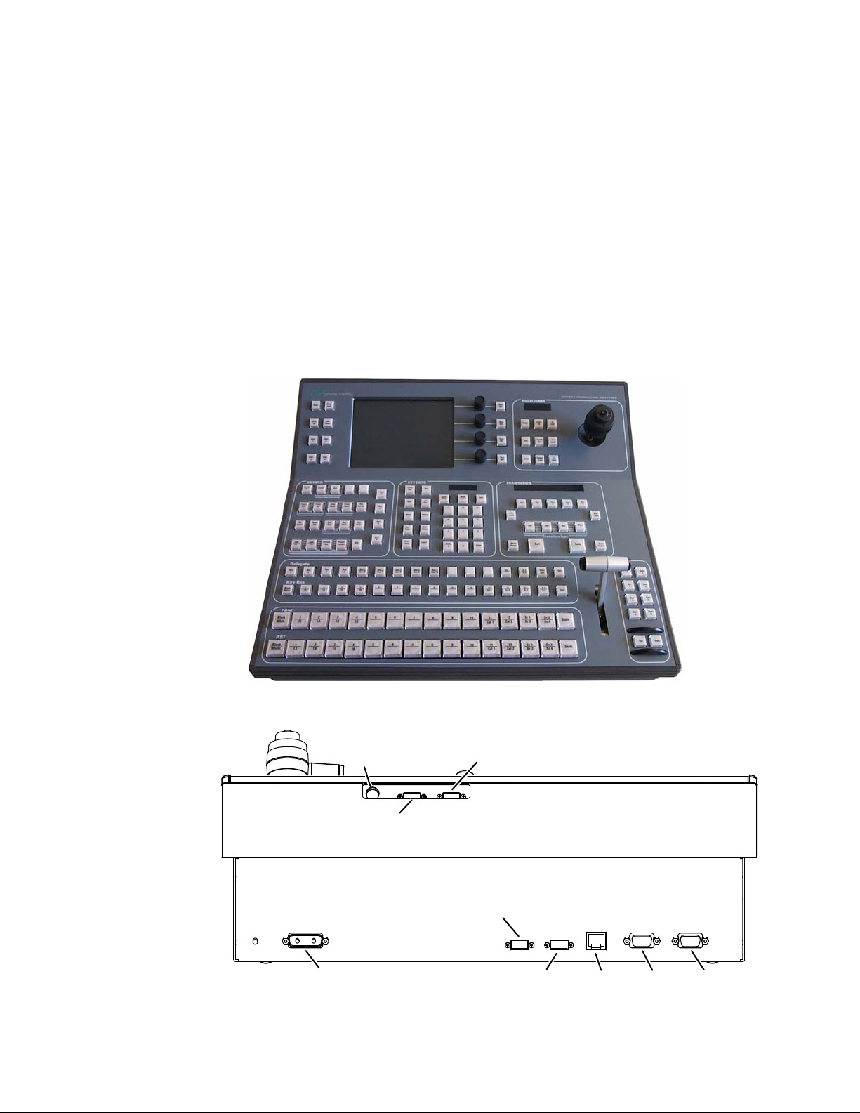
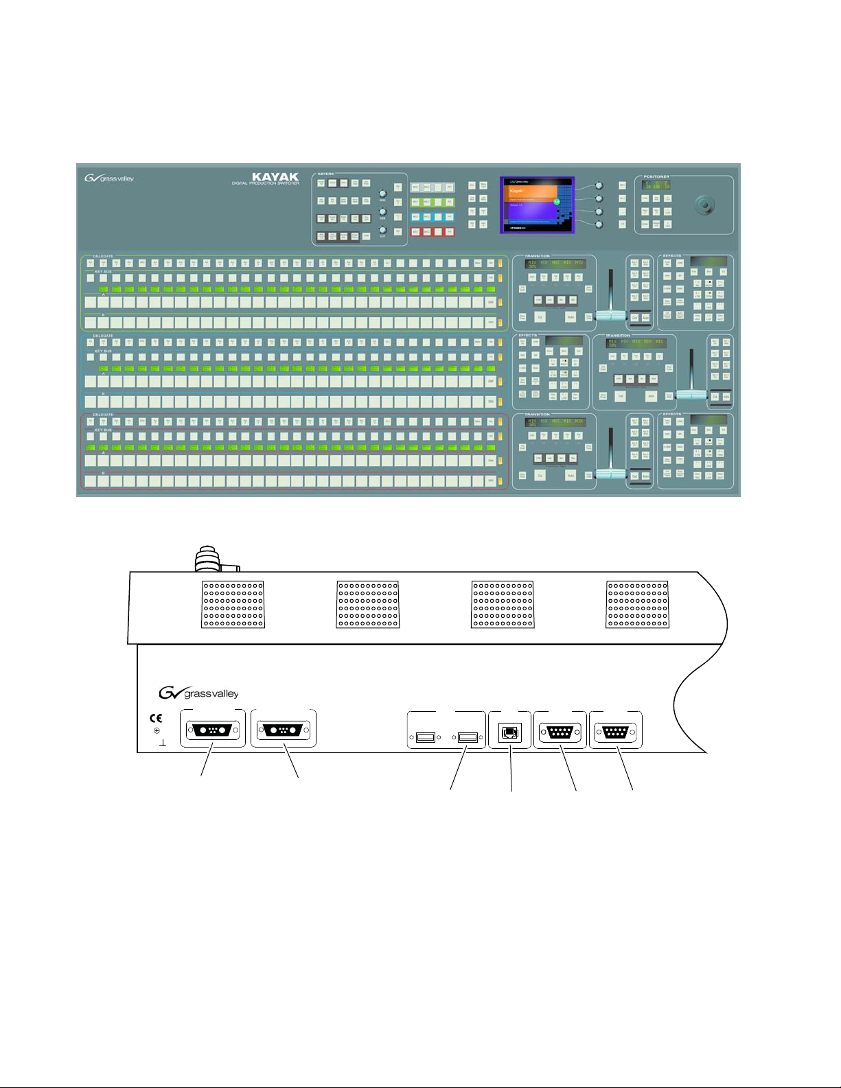
1 M/E Control Panel
Figure 1. 1 M/E Control Panel, Top View
Figure 2. 1 M/E Control Panel, Rear View
PS/2 Port
(Future use)
48V DC Power In (from Frame)
USB #4
(Future use)
USB #2
8448_04_r0
LAN RS 485 RS 232
26 Kayak HD — Installation and Service Manual
Page 27
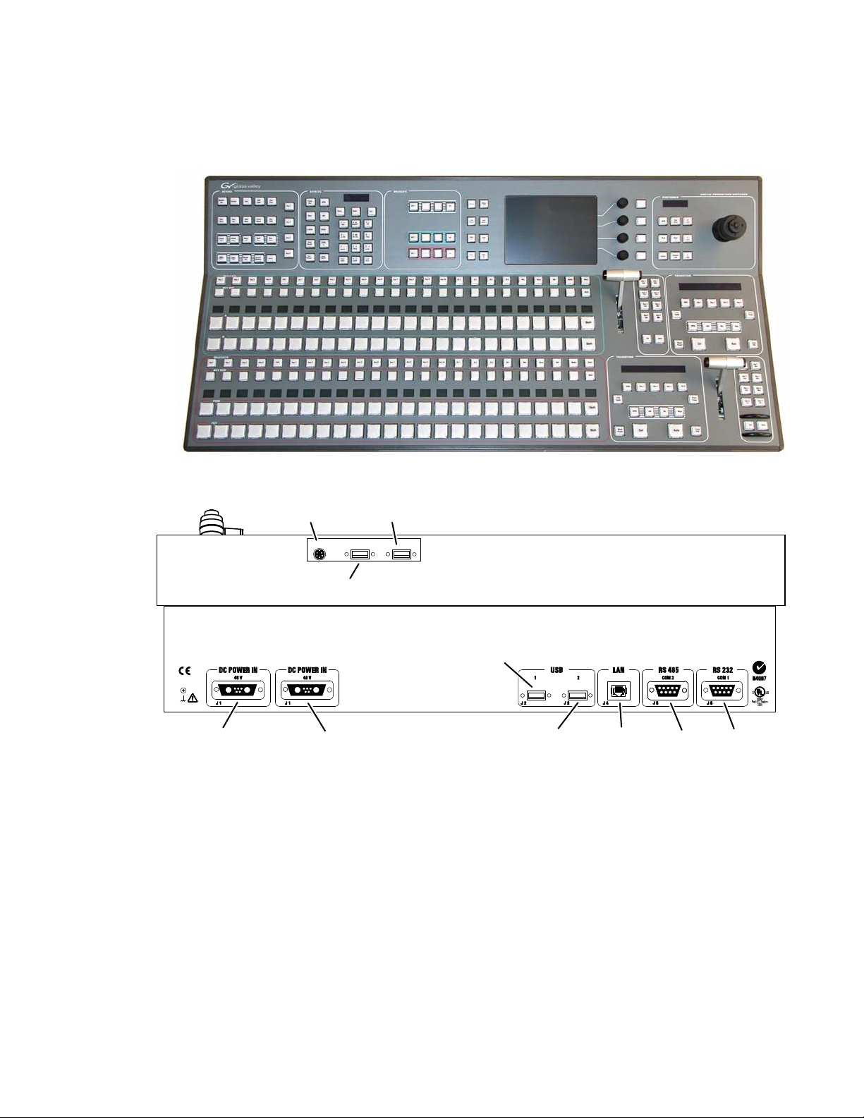
1.5 and 2 M/E Control Panel
USBP/S 2
3
4
8448_05_r0
(Future use)
(Future use)
PS/2 Port
48V DC Power In
(from Frame)
Redundant
DC Power In
USB #4
LAN RS 485 RS 232USB #2
Figure 3. Kayak HD 150C, 200C, and 200 Control Panel
System Components
Figure 4. 2 M/E Control Panel, Rear View
Kayak HD — Installation and Service Manual 27
Page 28
Section 1 — System Overview
J1A J1B
DIGITAL PRODUCTION SWITCHER
J2 J3
J4
J5
J5
DC POWER IN
48V/1.3A max. 48V/1.3A max.
RED. DC POWER IN
USB
LAN RS 485
RS 232
1
2
COM 2
COM 1
Spare
TE
KAYAK
48V DC Power In
(from Frame)
Redundant
DC Power In LANUSB
RS 485 RS 232
8448_12_r0
2.5 and 3M/E Control Panel
Figure 5. Kayak HD 250C, 250, and 300 Control Panel
Figure 6. 3 M/E Control Panel, Rear View
28 Kayak HD — Installation and Service Manual
Page 29
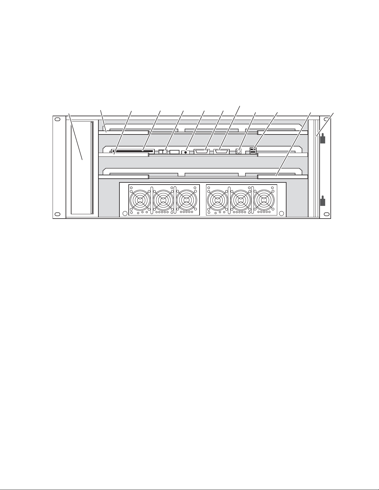
Kayak HD Video Processor Frames
ON
OFF
Top M/E Slot
M/E 0 (PP)
Bottom M/E Slot
(M/E 1)
Controller
(and 0.5 M/E)
2 USB
(unused)
Air Filter
Fan Assembly
Flash
Memory
Power
Switch
Reset
Button
RS-232
Power Supply Unit 1 Redundant Power Supply Unit 2 (option)
8448_01_r1
PS2
Keyboard
VGA
Kayak 4 RU Frame
Figure 7. Kayak HD 4RU Frame, Front View with Door Removed
System Components
Kayak HD — Installation and Service Manual 29
Page 30
Section 1 — System Overview
ON
OFF
M/E 0
(PP)
M/E 1
M/E 2
M/E 3
Expansion
Slot
Controller
(and 0.5 M/E)
Fan Assembly Flash
Memory
Power
Switch
Reset
Button
2 USB
(unused)
Air Filter
Power Supply Unit 1 Power Supply Unit 2 Power Supply Unit 3 (Optional)
RS-232 PS2
Keyboard
VGA
8448_11_r1
Kayak 8 RU Frame
Figure 8. Kayak HD 8RU Frame, Front View with Door Removed
30 Kayak HD — Installation and Service Manual
Page 31

KDD-PSU Power Supply Option
8448_17_r0
The KDD-PSU option is a one-rack unit, wide range AC power supply providing power for a remotely-mounted Kayak HD Control Panel or for each
additional Control Panel connected to the same processor chassis.
Power output is sufficient for two 1 M/E systems or one 2 M/E system.
Grass Valley recommends that customers purchase this option if the distance from the Frame to the Control Panel is more than 100 meters.
Figure 9. KDD-PSU
System Components
KDD-PSU-Front-Left
Figure 10. KDD-PSU Rear View
Kayak HD — Installation and Service Manual 31
Page 32

Section 1 — System Overview
Video Signal Flow
The basic video signal flow (Figure 11 on page 33) of the Kayak HD system
has been designed for operational flexibility. For example, all the outputs
from the M/E are routed back to the video crosspoint matrix, making all
these signals accessible to the entire system.
The video inputs to the Video Processor frame can be mapped to any of the
crosspoint buttons.
Internally generated white, black and three color backgrounds are also
available sources, as are the six RAMRecorder outputs. This source-tobutton mapping is performed through the touch screen menu and can be
stored as a user profile for any number of individual users. Button mapping
is the same on all buses.
The selected video on each bus is deserialized and reclocked before
entering the video processing circuitry. Video processing is available for
each separate M/E background, Key, and Utility bus. In addition, contrast,
brightness, and hue can be adjusted on a bus-by-bus basis.
Each M/E has four full-function keyers with optional internal Digital
Picture Manipulator effects. Each keyer has access to its own wipe gener
ator as well as a pair of standard flexible chroma keyers which may be
assigned to any keyers in the system. Two complex wipe generators serve
each M/E, providing a wide range of wipe choices with modulation, rota
tion and multiplication of each one. Wipe signals can also be taken from the
two Utility buses on the M/E.
The outputs from M/E Program, Preview, and clean feed are fed back to the
crosspoint circuitry for the selection on the Auxiliary buses as well as the
clean feed output.
The AUX bus outputs can be utilized in a number of ways. Every AUX bus
provides individually adjustable safe area and crosshair (center cross)
capability. Each AUX bus is timed to the reference.
-
-
32 Kayak HD — Installation and Service Manual
Page 33

Figure 11. Kayak HD Video Signal Flow
Des
A T
Σ
Ser
Deserializer
Auto Timer
Diagnostic Checksum Accumulator
Serializer
1.485 Gb/s or 270 Mb/s Dierential Serial
SMPTE SD or HD SDI
Various Parallel Video Buses
Kayak HD
2½ M/E Simplied
Video Block Diagram
Future Use
Variable Delay
1
2
4
5
6
7
8
9
10
11
12
13
14
15
16
17
18
19
20
21
22
23
24
3
Ser
Des
1
2
3
4
5
6
7
8
9
10
11
12
Analog HD Reference
Variable Delay
Ser
Des
Variable Delay
Ser
Des
Variable Delay
Ser
Des
Variable Delay
Ser
Des
Variable Delay
Ser
Des
Variable Delay
Ser
Des
Variable Delay
Ser
Des
Variable Delay
Ser
Des
Variable Delay
Ser
Des
Variable Delay
Ser
Des
Variable Delay
Ser
Des
A T
Des
A T
Des
A T
Des
A T
Des
M/E 1 Key 1 Video
Key
Processing
M/E 1 Key 1 Key
M/E 1 Key 2 Video
M/E 1 Key 2 Key
A T
Des
A T
Des
M/E 1 Bkg A
Background
Processing
M/E 1 Bkg B
Mixer
Ser
Pgm A
2 Key Wipe Gen
Σ
Σ
Σ
Σ
Σ
Σ
Σ
Σ
Σ
Σ
Σ
Σ
Σ
Σ
Σ
Σ
Σ
Σ
Σ
A T
Des
A T
Des
A T
Des
A T
Des
M/E 1 Key 3 Video
Key
Processing
M/E 1 Key 3 Key
M/E 1 Key 4 Video
M/E 1 Key 4 Key
A T
Des
A T
Des
M/E 1 Bkg C
Background
Processing
M/E 1 Bkg D
2 Key Wipe Gen
Σ
Σ
Σ
Σ
Σ
Σ
A T
Des
Eect Send Return 3
Σ
A T
Des
Eect Send Return 4
Σ
M/E 1 Pgm A
M/E 1 Pvw A
M/E 1 Pgm B
M/E 1 Pvw B
M/E 1 Eect Send 1
M/E 1 Eect Send 2
Crosspoint
144 x 144
M/E 1 Mix Eect Board
Main Board
Ser
Pvw A
Σ
Ser
Pgm B
Σ
Ser
Pvw B
Σ
Ser
Eects Send 1
Σ
Ser
Σ
Eects Send 2
Video Proc
Video Proc
Video Proc
Video Proc
Video Proc
Video Proc
Video Proc
Video Proc
Video Proc
Video Proc
Video Proc
Video Proc
Variable Delay
25
48
Ser
Des
13
Variable Delay
Ser
Des
Σ
Σ
M/E 2 Mix Eect Board
Video Proc
Video Proc
Analog SD Reference
2 Complex Wipe Gen
2 Complex Wipe Gen
A T
Des
Eect Send Return 1
Σ
A T
Des
Eect Send Return 2
Σ
Transform
Engine
Transform
Engine
Ser
Eects Send 3
Σ
Ser
Σ
Eects Send 4
Section A
Section B
Sync Generator
Background
Generator
Bgk 1
Bgk 2
Black
White
Ram Recorder/
Stillstore
Ch 1
Ch 2
Ch 3
Ch 4
Ch 1
Ch 2
Ch 3
Ch 4
Des
Ser
Des
Des
Des
Ser
Ser
Ser
Ser
Ser
Ser
Ser
A T
Des
A T
Des
A T
Des
Float 1 Key Video
Float
Keyer
&
Mixer
Float 1 Key Key
Float 1 Bkg
Σ
Σ
Σ
A T
Des
A T
Des
A T
Des
Float 2 Key Video
Float
Keyer
&
Mixer
Float 2 Key Key
Float 2 Bkg
Σ
Σ
Σ
A T
Des
A T
Des
A T
Des
HM/E Key 1 Video
Float
Half M/E
DSK
HM/E Key 1 Key
Σ
Σ
Σ
A T
Des
A T
Des
A T
Des
Σ
Σ
Σ
A T
Des
A T
Des
A T
Des
Σ
Σ
Σ
A T
Des
Σ
HM/E Key 2 Video
HM/E Key 2 Key
HM/E Key 3 Video
HM/E Key 3 Key
HM/E Key 4 Video
HM/E Key 4 Key
HM/E Bkg A
HM/E Bkg B
HM/E Pgm A
HM/E Pvw A
HM/E Pgm B
Σ
Σ
Σ
Σ
Σ
Σ
Σ
Σ
Σ
Σ
Σ
Σ
Float 1 Mix
Float 2 Mix
Ser
Pgm A
Σ
Ser
Pvw A
Σ
Ser
Pgm B
Σ
Ser
Pvw B
Σ
Ser
Float 1 Mix
Σ
Ser
Float 2 Mix
Σ
Des
Σ
Digital Reference
Des
Σ
Timing Analyzer
HM/E Pvw B
Timing Analyzer
Ch 5
Ch 6
Des
Des
Σ
Σ
Ch 5
Ch 6
Ser
Ser
Σ
Σ
to
to
48
8448_02_r0
Video Signal Flow
Kayak HD — Installation and Service Manual 33
Page 34

Section 1 — System Overview
34 Kayak HD — Installation and Service Manual
Page 35

Installation
Pre-Installation Procedures
Before you physically install the Kayak HD system, familiarize yourself
with the tools required, physical specifications, and safety and power
requirements covered in this section.
System Survey
Check all parts received against the packing list enclosed with your shipment, and examine the equipment for any shipping damage. Immediately
report any missing or damaged items to the carrier and to your Thomson
Grass Valley Service Representative.
Section 2
Line Voltage
Required Tools
Kayak HD components utilize auto-ranging power supplies which accommodate 100 - 240V. No switch settings are required, nor are any possible.
The following tools are required for installation, but are not supplied:
• Medium flat blade screwdriver,
• Medium Philips cross head screwdriver,
• #10, #15, & #20 Torx screwdrivers, and
• 1/4 inch Hex driver.
Kayak HD — Installation and Service Manual 35
Page 36

Section 2 — Installation
Safety Requirements
To prevent injury or equipment damage, read, understand, and follow all
installation safety precautions.
CAUTION The Video Processor frame weighs approximately 8.3 kg (18.3 lb). Provide
WARNING Electrical potential is still applied to some internal components even when
CAUTION To avoid static damage to sensitive electronic devices, protect the Kayak HD
WARNING Operate only with covers and enclosure panels in place — Do not operate
appropriate equipment to support the frame during installation.
power to the frame is off. To prevent electrical shock when working on this
equipment, disconnect the AC line cords from the AC source before
working on any internal components. Residual voltage may be present
immediately after unplugging the system; wait thirty seconds to allow
capacitors to discharge before working on the system.
system from static discharge. Avoid handling frame modules in a high static
environment. Use a grounding strap when handling modules, and touch the
frame before you remove any modules.
this product when covers or enclosure panels are removed.
Installation Tasks
After completing the Pre-Installation procedures, the recommended installation tasks given in this section are:
1. Unpack the equipment.
2. Install the Kayak HD Video Processor frame.
3. Install the Kayak HD control panel(s).
4. Connect all cables between Kayak HD devices.
5. Connect cables to video inputs and outputs.
6. Connect the power cables.
Power up and configuration, including setting IP addresses, is covered in
detail in the following sections of this manual.
36 Kayak HD — Installation and Service Manual
Page 37

General Rack Mounting Instructions
177 mm
6.97 in.
482 mm
19.0 in.
465 mm
18.31 in.
165 mm
6.5 in.
Front view
8451_15.1_r1
The maximum ambient temperature for this unit is 40-degrees C (104degrees F).
Installing the frame in a closed or multi-unit rack assembly together with
other units could increase the maximum ambient temperature for this unit.
If the unit is installed in a rack, no ventilation openings should be blocked
or otherwise covered. Make sure you install the frame so that you allow for
cooling airflow.
Make sure that you mount the unit in the rack so that it is evenly balanced
to prevent damage to the frame and to avoid creating a hazardous condi
tion.
When connecting the unit to the supply circuit be sure that the supply
circuit of the rack is not overloaded. The unit must be well-grounded using
the ground connector on the rear. When connecting the unit in a closed or
multi-unit rack assembly together with other units be sure that the sum of
the touch (leakage) currents for all power supplies does not exceed 3.5 mA.
General Rack Mounting Instructions
-
4 RU Frame
Video Processor Frame Installation
4 RU Compact Frame Dimensions
Figure 12. Kayak HD 4 RU Frame Dimensions
Kayak HD — Installation and Service Manual 37
Page 38

Section 2 — Installation
Figure 13. Kayak HD 4 RU Frame Dimensions
442 mm
17.4 in.
7.5 mm
0.3 in.
523 mm
20.58 in.
37 mm
1.43 in.
Top view
541 mm
21.29 in.
8451_15.2_r0
38 Kayak HD — Installation and Service Manual
Page 39

4 RU Compact Frame Rack Mounting
Figure 14. Kayak HD 4 RU Compact Frame Rack Mounting
Air
Exhaust
4 RU Frame
Rear Rack
Support
Air
Intake
8451_05_r3
CAUTION Mounting using only the front rack ears is sufficient for fixed installations.
Additional support, like the rear rack support or slide rails, is required for
mobile applications.
The Rear Rack support provides additional support and stability for the
Kayak HD frame to ensure that it remains horizontal.
Make sure to provide adequate ventilation for the Kayak HD Frame. When
installing the frame in the rack, take care that no ventilation holes are
blocked. This can prevent cooling air from reaching the frame and cause it
to overheat.
There are air intake holes on the right side of the frame (as you face the
frame front) and air exhaust holes on the left.
CAUTION A minimum vertical clearance of 7.62 mm (0.3-in.) above the Kayak HD 4 RU
Compact frame door is required to remove the door. When installing the
Kayak HD 4 RU Compact frame in the rack, take care to leave room for
removal of the front door. The front door lifts off vertically and must have suf
ficient clearance room in order to remove it. If you have equipment mounted
too close to the Kayak HD 4 RU Compact Frame, you may not be able to
remove the door.
-
Kayak HD — Installation and Service Manual 39
Page 40

Section 2 — Installation
ON
OFF
Top M/E Slot
M/E 0 (PP)
Bottom M/E Slot
(M/E 1)
Controller
(and 0.5 M/E)
2 USB
(unused)
Air Filter
Fan Assembly
Flash
Memory
Power
Switch
Reset
Button
RS-232
Power Supply Unit 1 Redundant Power Supply Unit 2 (option)
8448_01_r1
PS2
Keyboard
VGA
Kayak HD Video Processor 4 RU Frame
Figure 15. Kayak HD 4RU Frame, Front View with Door Removed
Grounding Lug
1 M/E: 1-24
Figure 16. Kayak HD 4RU Frame, Backplane View
Video In
2 M/E: 1-48
48V DC Power Out
(to Control Panel)
Video Out
1 M/E: 1-12
2 M/E: 1-24
SD Reference In
Redundant AC
Power Supply 2
(option)
GPI In 1-8
GPI Out 1-32
HD Reference In
Tri Level Sync
100-240V AC
Power Supply 1
(Internal Switch
with 4 Ports)
LAN
LINK/ACTIVITY
OFF-10
AMBER-100
GREEN-1000
GPI In 9-16
GPI Out 33-64
(2 M/E only)
RS422/485
Serial Ports
(8)
8448_06_r1
40 Kayak HD — Installation and Service Manual
Page 41

License EEPROMs
Kayak systems use two EEPROM (Electronically Erasable Programmable
Read Only Memory) chips to set the licenses that determine which features
are available for use. Licensing is keyed off of the serial number for the
Kayak frame.
Note If you have a frame and are replacing it with a new frame, the new license
Figure 17. License EEPROMs in 4 RU Frame, Main Controller Board and ME0 Removed
Top M/E Connectors
(Board Removed)
4 RU Frame
stored in the EEPROM chips for the new frame is issued to the serial number
for the new frame.
License
EEPROMs
Main Controller
Board Connectors
(Board Removed)
Note If you have to exchange your frame for any reason you may want to first pull
the two EEPROMs to put in your new frame. Make sure they are put in the
right position (the same position they had on the older frame).
Note You should always keep a copy of your license text file or you may lose all
features, including Inputs, chroma keys, and DPMs. If you have lost your
license, contact Customer Service. (See
Contacting Grass Valley on page 4.)
8448_20_r2
Kayak HD — Installation and Service Manual 41
Page 42

Section 2 — Installation
483 mm
19.0 in.
465 mm
18.31 in.
166 mm
6.5 in.
178 mm
7.0 in.
355 mm
13.97 in.
8451_16_r0
Front view
8 RU Frame
Video Processor Frame Installation
8 RU Frame Dimensions
Figure 18. Kayak HD 8 RU Frame Dimensions 1 of 2
42 Kayak HD — Installation and Service Manual
Page 43

Figure 19. Kayak HD 8 RU Frame Dimensions 2 of 2
523 mm
20.58 in.
541 mm
21.29 in.
Cable Support Wires
442 mm
17.4 in.
8451_13_r1
Top view
37 mm
1.43 in.
8 RU Frame
Kayak HD — Installation and Service Manual 43
Page 44

Section 2 — Installation
Air
Intake
Rear Rack
Support
Air
Exhaust
8451_14_r1
8 RU Frame Rack Mounting
Figure 20. Kayak HD 8 RU Frame Dimensions
CAUTION Mounting using only the front rack ears is sufficient for fixed installations.
Additional support, like the rear rack support or slide rails, is required for
mobile applications.
The Rear Rack support provides additional support and stability for the
Kayak HD frame to ensure that it remains horizontal.
44 Kayak HD — Installation and Service Manual
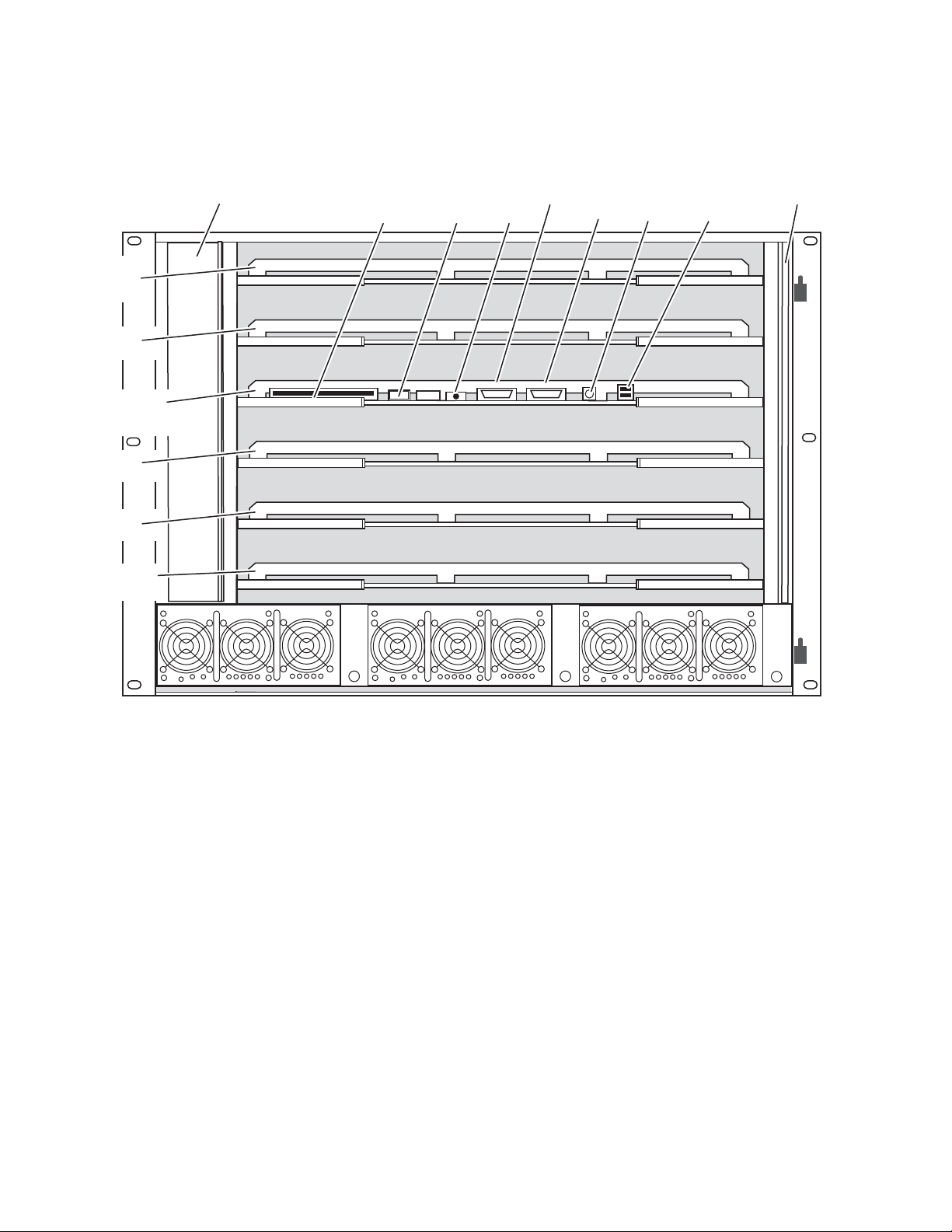
Page 45

8 RU Frame
ON
OFF
M/E 0
(PP)
M/E 1
M/E 2
M/E 3
Expansion
Slot
Controller
(and 0.5 M/E)
Fan Assembly Flash
Memory
Power
Switch
Reset
Button
2 USB
(unused)
Air Filter
Power Supply Unit 1 Power Supply Unit 2 Power Supply Unit 3 (Optional)
RS-232 PS2
Keyboard
VGA
8448_11_r1
Make sure to provide adequate ventilation for the Kayak HD Frame. When
installing the frame in the rack, take care that no ventilation holes are
blocked. This can prevent cooling air from reaching the frame and cause it
to overheat.
There are air intake holes on the right side of the frame (as you face the
frame front) and air exhaust holes on the left.
CAUTION A minimum vertical clearance of 7.62 mm (0.3-in.) above the Kayak HD 8 RU
frame door is required to remove the door. When installing the Kayak HD 8
RU frame in the rack, take care to leave room for removal of the front door.
The front door lifts off vertically and must have sufficient clearance room in
order to remove it. If you have equipment mounted too close to the Kayak HD
8 RU Frame, you may not be able to remove the door.
Figure 21. Kayak HD 8RU Frame, Front View with Door Removed
Kayak HD — Installation and Service Manual 45
Page 46

Section 2 — Installation
8448_64_r0
48V DC Power Out
(to Control Panel)
100-240V AC
Power Supply 1
Redundant AC
Power Supply 3
(option)
100-240V AC
Power Supply 2
Grounding Lug
GPI In 9-16
GPI Out 33-64
(2 M/E only)
GPI In 1-8
GPI Out 1-32
HD Reference In
Tri Level Sync
Video Out
1 M/E: 1-12
2 M/E: 1-24
3 M/E: 1-48
Video In
1 M/E: 1-24
2 M/E: 1-48
3 M/E: 1-96
SD Reference In
LAN
(Internal Switch
with 4 Ports)
RS422/485
Serial Ports
(8)
Figure 22. Kayak HD 8RU Frame, Backplane View
46 Kayak HD — Installation and Service Manual
Page 47

Kayak HD Frame Connectors
Table 1. Kayak HD Frame Connectors
AC POWER IN 1
AC POWER IN 2
AC POWER SWITCH Frame power switch.
INPUTS
IN1 – IN24
INPUTS
IN25 - IN48
INPUTS
IN49 - IN73
(8 RU FRAME ONLY)
INPUTS
IN74 - IN96
(8 RU FRAME ONLY)
24 MAPPABLE OUTPUTS BNC / Serial Comp (ITU-R 656)
AUX 1 – AUX10 Auxiliary Outputs, BNC / Serial Comp (ITU-R 656)
SD ANALOG REFERENCE INPUT PAIR Reference input, BNC / 75 ohms
HD ANALOG REFERENCE INPUT PAIR Reference input, BNC / 75 ohms
RS 422/485 PORTS
(PORTS 1-8)
GPI / GPO / TALLY
INPUTS 1-8, 9-16
OUTPUTS 1-32, 33-64
LAN Four RJ45 connectors for LAN connection to the Control Panel. Optional
DC POWER IN Input connector for external DC Power Supply Unit (KDD-PSU) for redun-
DC POWER OUT Output connector for Panel DC Power Supply.
Kayak HD Frame Connectors
Designation Note
Mains connectors (IEC-320, CEE-22) to provide power supply to the
video processor frame.
Operating Voltage: 100V-240V AC +/-10% widerange
Caution: For continued protection against risk of fire, replace only with
same type and rating of fuse. 2x T 6.3A /H 250
Double-pole or neutral fusing — Disconnect mains power prior to servicing. After a fuse opens, high voltage in parts of the equipment may still
present a hazard to you during servicing.
BNC / Serial Comp (ITU-R 656) video inputs
Maximum cable length 100m HD, 300m SD (typical).
BNC / Serial Comp (ITU-R 656) video inputs
In 25 …48: Maximum cable length 100m HD, 300m SD (typical).
NOTE: The last 4 inputs in each group have the scalar option.
BNC / Serial Comp (ITU-R 656) video inputs
In 49 …73: Maximum cable length 100m HD, 300m SD (typical).
NOTE: The last 4 inputs in each group have the scalar option.
BNC / Serial Comp (ITU-R 656) video inputs
In 74 …96: Maximum cable length 100m HD, 300m SD (typical).
NOTE: The last 4 inputs in each group have the scalar option.
Double Program output
Preview output
Clean output
Clean Preview output
Loop through sync input for analog Blackburst or CCVS signal.
Loop through sync input for Tri Level Sync.
Eight control ports, 9-pin D-type female
RS422/485 serial ports for devices such as DVEs, Editors, Routers and for
Machine Control (Disk Servers, VTR).
50-pin D-type female
General-purpose interface connector with 8 input channels and 32 output
channels.
The connector is used for Tally also.
Refer table below for respective pin assignment.
cables with lengths of 20m or 50m can be ordered.
dancy (High current D-Sub, female). (See KDD-PSU Power Supply Option
on page 58.)
Input voltage: 48V/ 5A
Note: The external power supply unit must comply with the SELV (Safety
Extra Low Voltage) standard exclusively. ELV and TNV standard is not per
mitted.
Additionally the 8V DC voltage for RAM Recorder buffering can be supplied via this socket.
(High current D-Sub, male).
Output voltage: 48V/ 1.6A max.
A 10m DC power connecting cable is supplied.
-
Kayak HD — Installation and Service Manual 47
Page 48

Section 2 — Installation
Internal Redundant Power Supply Option
This option provides redundant power for the Kayak HD video processor
chassis and control panel. It slides into an extra power supply slot in the
video processor chassis.
Figure 23. KHD-PSU Internal Redundant Power Supply Option
Removing and Replacing the Kayak HD Frame Door
WARNING Be very careful when opening the Kayak HD frame door. Take precautions
to avoid electrical shock from components by following the safety precau
tions described in detail in Warnings on page 18 and in Cautions on
page 19. In particular you want to avoid the possibility of electrical shock
by powering down the system and unplugging all equipment before
working on internal components. In addition you should wear a grounding
strap to prevent electrical damage to sensitive electronic components.
CAUTION Operate only with covers and enclosure panels in place — Do not operate
this product when covers or enclosure panels are removed.
You need to take care not to damage the door by following the procedures
described below.
Note A minimum vertical clearance of 7.62 mm (0.3-in.) above the Kayak HD 4 RU
Compact frame door is required to remove the door. When installing the
Kayak HD 4 RU Compact frame in the rack, take care to leave room for
removal of the front door. The front door lifts off vertically and must have suf
ficient clearance room in order to remove it. If you have equipment mounted
too close to the Kayak HD 4 RU Compact Frame, you may not be able to
remove the door.
-
-
48 Kayak HD — Installation and Service Manual
Page 49

Removing and Replacing the Kayak HD Frame Door
8451_19_
r2
2
3
1
To remove the Kayak HD frame door:
1. Turn the lock on the front door of the Kayak HD Frame 180-degrees
counterclockwise to unlock it.
2. Open the door to less than 90-degrees from the Frame.
3. Holding both ends of the Frame door, lift the door vertically to remove
it from the hinge pins. Be careful not to damage the door. Refer to
Figure 24.
Figure 24. Open the door to less than 90-degrees from the frame and lift vertically
To replace the Kayak HD frame door:
1. Holding both ends of the Frame door, position the door hinges over the
two vertical pins on the frame.
2. Using both hands to hold the door at opposite ends, gently lower the
door so that its hinges are placed on the two pins. Be careful not to
damage the door.
3. Turn the lock on the front door of the Kayak HD Frame 180-degrees
clockwise to lock it.
Kayak HD — Installation and Service Manual 49
Page 50

Section 2 — Installation
8324_01_r2
418 mm
16.46 in.
398 mm
15.66 in.
10 mm
0.39 in.
34 mm
1.31 in.
16 mm
0.60 in.
11 mm
0.40 in.
66 mm
2.55 in.
81 mm
3.19 in.
260 mm
10.23 in.
145 mm
5.69 in.
Left side view
20°
7°
Control Panel Installation
1 M/E Control Panel
Figure 25. Kayak HD 100C Control Panel Dimensions 1 of 2
50 Kayak HD — Installation and Service Manual
Page 51

Figure 26. Kayak HD 100C Control Panel Dimensions 2 of 2
Control Panel Installation
Front view
10 mm
0.39 in.
418 mm
16.5 in.
448 mm
17.64 in.
428 mm
16.85 in.
10 mm
0.39 in.
Top view
448 mm
17.64 in.
8324_02_ r2
Kayak HD — Installation and Service Manual 51
Page 52

Section 2 — Installation
2 M/E Control Panel
Figure 27. Kayak HD 150C and 200C Control Panel Dimensions 1 of 2
418 mm
1445 mm
5.69 in.
16.46 in.
260 mm
10.23 in.
65 mm
2.55 in.
81 mm
3.19 in.
11 mm
0.40 in.
20°
7°
398 mm
15.66 in.
16 mm
0.60 in.
34 mm
1.31 in.
8451_08_r2
10 mm
0.39 in.
52 Kayak HD — Installation and Service Manual
Page 53

Control Panel Installation
w
Figure 28. Kayak HD 150C, 200C, and 200 Control Panel Dimensions 2 of 2
Front vie
10 mm
0.39 in.
418 mm
16.5 in.
809 mm
31.9 in.
789 mm
31.1 in.
809 mm
31.9 in.
10 mm
0.39 in.
Top view
8451_09_r0
Kayak HD — Installation and Service Manual 53
Page 54

Section 2 — Installation
44.57 in.
1132 mm
43.78 in.
1112 mm
0.39 in.
10 mm
0.39 in.
10 mm
21.42 in.
544 mm
8451_10_r0
Front view
Top view
3M/E Control Panel
65 mm
2.54 in.
97 mm
3.79 in.
10 mm
0.39 in.
Figure 29. Kayak HD 250C, 250, and 300 Control Panel Dimensions
20°
Left side view
524 mm
20.63 in.
7°
10 mm
0.39 in.
34 mm
1.31 in.
8451_01_r0
54 Kayak HD — Installation and Service Manual
Page 55

Panel Mounting Options
Kayak HD control panels may be placed on a table or similar stable surface,
or they may be recessed into a control console in an appropriately sized
cutout.
Table Top Use
High-friction feet prevent inadvertent movement of the panel. The panel is
ventilated at its sides. Ensure that production materials and other equip
ment does not block the ventilation holes on the sides of the panel.
CAUTION At least 2 in. (50mm) of open space on the sides of the panel is required for
proper air flow.
Surface Mount Cutout Dimensions
Table 1. Kayak HD Surface Mount Cutout Dimensions
Control Surfaces A B
Kayak HD 250C, 250, 300 526 mm (20.71 in.) 1114 mm (43.86 in.)
Kayak HD 150C, 200C,
200
Kayak HD 100C 400 mm (15.75 in.) 430 mm (16.93 in.)
Cutout Dimensions
400 mm (15.75 in.) 791 mm (31.14 in.)
Control Panel Installation
-
A
B
0619_00_27_r1
CAUTION At least 50 mm (2 in.) of clear space on the sides of the panel below the
mounting surface is required for proper air flow. Provide at least 50 mm (2
in.) of clear space in the rear of the panel for cable clearance.
Kayak HD — Installation and Service Manual 55
Page 56

Section 2 — Installation
5 mm (0.2 in.)
panel edge to centerline
of threaded hole
8324_10_r3
Securing Panels to Mounting Surface
When mounting the panel in a tabletop cutout, four M4 threaded holes
(two each on the left and right side of the panel) are available for securing
the panel in the cutout (
Figure 30. Kayak HD Panel Mounting Holes
Figure 30).
56 Kayak HD — Installation and Service Manual
Page 57

Kayak HD Control Panel Connectors
Figure 31. Kayak HD Control Panel Rear Connectors
Table 1. Kayak HD Control Panel Connectors
Jack Designation Note
J1-A
J1-B
J2
J3
J4
J5
J6
DC POWER IN DC power input connector for 48V operating voltage. Connecting with the DC POWER OUT at the
Processor Frame. An interconnecting cable with a length of 10 m (32ft.) is supplied.
Optional cables of 50m (164 ft) and 100m (328 ft.) length can be used. For longer distances a separate KDD-PSU 48V power supply unit must be connected to the RED. DC POWER IN connector.
Note: The external power supply unit must comply with the SELV (Safety Extra Low Voltage) standard exclusively. ELV and TNV standard is not permitted.
RED. DC POWER INDC power input connector for 48V operating voltage from Redundant Power Supply Unit KDD-
PSU. Optional cables of 20m (64 ft) length can be used.
M4 threaded pin Screw terminal used for additional unit grounding.
USB 1 Spare USB port, reserved for future use.
USB 2 Connectors for USB devices such as a CD-ROM Drive, mouse, keyboard or USB flash drive. For a
list of recommended USB flash drive refer to the section on Recommended USB Flash Drives in the
Kayak Release Notes. Only recommended devices are supported.
LAN RJ45 connector for connection from the panel to the video processor frame.
RS 422/485 RS422/RS485 interface for connecting external devices. The software control automatically
switches over the interface to master or slave (bus control/tributary), depending on which unit
driver has been selected in the menu.
RS 232 RS232 interface for connecting a computer or other external devices for diagnostics.
USB 3 Spare USB port, reserved for future use.
USB 4 Connectors for USB devices such as a CD-ROM Drive, mouse, keyboard or USB flash drive. For a
list of recommended USB flash drive refer to the section on Recommended USB Flash Drives in the
Kayak Release Notes. Only recommended devices are supported.
P/S 2 Used to connect a P/S 2 Mouse or Keyboard.
Control Panel Installation
8448_25_r0
Figure 32. Kayak HD Connectors Top Rear Control Panel
8448_26_r0
Kayak HD — Installation and Service Manual 57
Page 58

Section 2 — Installation
Cut fastening metal so that the
ventilation openings are not covered
8324_14_r1
KDD-PSU Power Supply Option
The KDD-PSU is a 1RU frame designed for rack mounting (Figure 33).
Figure 33. KDD-PSU Rack Installation
Figure 34. KDD-PSU DC Power Connectors
Tab l e 2. K DD - PS U Rear Connectors
Jack Designation Note
J1
J2
J3
J4, J5
AC POWER IN Mains connector (IEC-320, CEE-22) for power supply. Operating Voltage: 100V-240V AC +/-10%
AC POWER IN Power switch
EXT. BATT IN
12V ... 24V DC
12V DC OUT For future use
DC POWER Two output connectors for DC Power Supply. (High current D-Sub, male).
Ground Terminal Terminal for grounding.
wide-range
Caution: For continued protection against risk of fire, replace only with same type and rating of fuse.
2x 8A /T H 250V
Terminal strip for connection to external battery for buffering the RAM-Recorder data.
Output voltage: 48V/ total 6A max
8448_19_r0
58 Kayak HD — Installation and Service Manual
Page 59

Pin Assignments
Pin 1Pin 5
Pin 6Pin 9
D-9 Female
Pin 1Pin 5
Pin 6Pin 9
D-9 Female
RS 422/485 Port
Table 3.
There are 8 RS485 ports that can be used for Machine Control of various
devices, or for switcher control by an external controller.
Pin Assignments
Socket Pin Bus Controller Tributary
Chassis Ground Chassis Ground
1
RxA (-) TxA (-)
2
TxB (+) RxB (+)
3
Signal Ground Signal Ground
4
Not used Not used
5
Signal Ground Signal Ground
6
RxB (+) TxB (+)
7
TxA (-) RxA (-)
8
Chassis Ground Chassis Ground
9
RS 232 Port
Table 4.
Socket Pin Signal
Chassis Ground
1
Transmit Data
2
Receive Data
3
Not used
4
Signal Ground
5
Not used
6
Clear to Send
7
Request to Send
8
Not used
9
There is an RS232 serial port, a keyboard port, and a VGA video output
located on front of the Controller Board. These ports are used for diagnos
tics. If you need to use these ports to diagnose problems with the Kayak HD
switcher, please contact your Grass Valley Customer Service Representa
tive.
-
-
Kayak HD — Installation and Service Manual 59
Page 60

Section 2 — Installation
Control Panel DC Power In
Table 5.
Socket Pin Signal
Pin A1
D-Sub Male
Pin 2Pin 1
Pin A2
Pin 5Pin 3
A1
A2
1
2
3
4
5
Frame DC Power Out
Table 6.
Socket Pin Signal
Pin A2
D-Sub Female
Pin 1Pin 2
Pi
Pin 3Pin 5
n A1
A1
A2
1
2
3
4
5
48 V (+)
48 V (-)
-
-
-
-
-
48 V (+)
48 V (-)
-
-
-
-
-
GPI / Tally Connections
The Kayak HD GPI / Tally system has universal relays that interface source
tally and GPI Output information to an external system through the Tally
Port connectors. The channels can be assigned in the Setup menu.
Tallies are a source attribute and relays can be assigned to a source when
source definitions are defined in the Setup menu during initial system con
figuration. The nominal rating specification for each relay is 1A, 60 V.
The GPI (General Purpose Interface) and Tally Interface provides a means
to transfer commands to and from the switcher to external customer pro
vided equipment. A “one wire per function” parallel hardware connection
is used.
Connectors and pins are provided to create a mating connector.
60 Kayak HD — Installation and Service Manual
-
-
Page 61

Kayak HD GPI and Tally Interface
The Kayak HD is highly modular and configurable. This document
describes various possibilities for tally interconnections.
There are two 50 pin female subminiature 'D' connectors on the rear of the
4 RU Kayak HD frame and four connectors on the rear of the 8 RU Kayak
HD frame. Each connector is activated by the presence of a Mix/Effects
module installed in the frame. A one M/E switcher (4 RU or 8 RU frame)
activates only the first connector. Two M/Yes activate two connectors, and
so forth, up to four connectors activated by a four M/E system.
GPI inputs and outputs are assigned as follows:
• GPI in 1 - 8 and GPI/Tally out 1 - 32 routed to the first connector.
• GPI in 9 - 16 and GPI/Tally out 33 - 64 routed to the second connector.
• GPI in 17 - 24 and GPI/Tally out 65 - 96 routed to the third connector (8
RU frame only).
• GPI in 25 - 32 and GPI/Tally out 97 - 128 routed to the fourth connector
(8 RU frame only).
GPI / Tally Connections
GPI Inputs
For pinouts of these connectors refer to the listings in:
• 4 RU and 8RU Frame Tally (GPI In 1-8, GPI Out 1-32) on page 66
• 4 RU and 8RU Frame Tally (GPI In 9-16, GPI Out 33-64) on page 67
• 8RU Frame Tally (GPI In 17-24, GPI Out 65-96) on page 68
• 8RU Frame Tally (GPI In 25-32, GPI Out 97-128) on page 69
These four connectors do not share any signals in common other than
ground reference and chassis ground. Because of this, some GPI / Tally
interconnects may require external common connections between connec
tors, as explained below.
The purpose of the GPI In pins is to provide a stimulus from the customer's
equipment to the switcher.
A simple connection to the two connectors (or four in the case of the 8 RU
frame) activates the corresponding input. This kind of control is suitable for
a connection to a relay contact or to an open-collector output.
-
WARNING When connecting to an open-collector output, there is no ground potential
isolation between the Video Processor frame and controlling devices.
Since the circuit ground is led out of the device, the cabling has to be
shielded for this kind of control. Non-shielded cables may cause EMC
and/or ESD problems.
Kayak HD — Installation and Service Manual 61
Page 62

Section 2 — Installation
GPI Input Structure
To activate a GPI In you must provide switch closure between a particular
GPI In pin and one of the two GPI In Com pins (Pins 1 and 34).
Figure 35. GPI Input Connections (Typical 2 of 8 connections)
+ 3.3 V
GPI 1
GPI 5
Open
Collector
50-pin Connector
Pin Numbers
18
2
35
19
3
36
20
4
150 ohm
150 ohm
Opto Isolator
(1 of 8)
+ 3.3 V
Opto Isolator
(5 of 8)
1
Ground and
34
Kayak HD FrameUser Equipment
Chassis
Pins 1 and 34 of each of the two (four) connectors are connected to ground.
For applications that span across more than one connector, only one
ground (common) connection is required.
62 Kayak HD — Installation and Service Manual
8448_08r0
Page 63

The function of each GPI input is user assignable. The activation of the
function can be programmed to occur on the leading edge or the trailing
edge of the closure, or both edges. The switch must be closed for at least one
field.
Refer to the Install Menus section of the Kayak HD User Manual for details
on setting the input signal activating edge.
Refer to the Configuration Menu section of the Kayak HD User Manual for
details on setting the function of a GPI input.
GPI / Tally Outputs
There is a great deal of flexibility in the hardware and programmability of
the GPI / Tally outputs.
Outputs are arranged in groups of four. Each group has its own common
connection. These are labeled GPI_OUT_COM_A through
GPI_OUT_COM_H for the first connector (corresponding to GPI /Tally
OUTs 1 - 32). These commons can all be tied together, forming one common
bus for all 32 outputs. Alternatively, multiple smaller commons can be con
structed to interface with systems that need isolated common connections.
This common or isolated bus scheme can extend across multiple connec
tors. For example, a 4 M/E system could have all commons of all connectors tied together. All 128 relay closures will connect to one common bus.
Another case may require two isolated common buses - half of the
commons form the first common bus and the other half form the second
common bus.
GPI / Tally Connections
-
-
The example in Figure 36 on page 64 shows two common buses. The first
four outputs (COMMON A) have the common bus tied to ground. This
drives a logic system. The last outputs (COMMON G & COMMON H)
have the common bus tied to +12 volts. This drives a tally lamp system.
Kayak HD — Installation and Service Manual 63
Page 64

Section 2 — Installation
Figure 36. GPO Tally Connections
50-pin Connector
Pin Numbers
1A of 32
2A of 32
3A of 32
4A of 32
5B of 32
6B of 32
Common A
Common B
21
5
Logic
38
22
37
39
23
27G of 32
28G of 32
29H of 32
30H of 32
31H of 32
32H of 32
48
32
Common G
Common H
Kayak HD Frame User Equipment
47
49
33
17
50
16
12V Lamp
12V Lamp
12V Lamp
+ 12V DC
8448_09r0
64 Kayak HD — Installation and Service Manual
Page 65

GPI / Tally Connections
Although the diagram above implies mechanical relays, the actual outputs
are implemented with solid state relays. Interface specifications are:
Maximum current for any one output: 1 amp AC/DC
Maximum current for any one common: 2 amp AC/DC.
Maximum off (open circuit) voltage between output and common: 60
Vol ts p ea k.
Maximum voltage between any point and ground (chassis): 60 Volts
peak.
The solid state relays are bidirectional; either polarity voltage can be
applied. If the switcher GPI / Tally outputs are used to drive downstream
DC relays, be sure to install diodes across the relay coils to clamp inductive
spikes. Shielded cable is recommended for the connection from the
switcher to the user tally system.
Each output can be programmed for function, steady state or pulse, output
polarity, and pulse duration.
Refer to the Install Menus section of the Kayak HD User Manual for details
on setting the characteristics of the output signal (steady state, polarity,
pulse duration, etc.).
Refer to the Configuration Menu section of the Kayak HD User Manual for
details on setting the function of a GPO / Tally output (tally, auto trans,
recall register, and so forth).
Kayak HD — Installation and Service Manual 65
Page 66

Section 2 — Installation
4 RU and 8RU Frame Tally (GPI In 1-8, GPI Out 1-32)
Socket Ribbon Cable 50-Pin D-Sub Signal
1 1 GPIInCom
D-50 Female
Pin 18
Pin 1
Pin 34
Pin 33
Pin 17
Pin 50
2 34 GPIInCom
3 18 GPIIn1
4 2 GPIIn2
5 35 GPIIn3
6 19 GPIIn4
7 3 GPIIn5
8 36 GPIIn6
9 20 GPIIn7
10 4 GPIIn8
11 37 GPIOutComA
12 21 GPIOut1A
13 5 GPIOut2A
14 38 GPIOut3A
15 22 GPIOut4A
16 6 GPIOutComB
17 39 GPIOut5B
18 23 GPIOut6B
19 7 GPIOut7B
20 40 GPIOut8B
21 24 GPIOutComC
22 8 GPIOut9C
23 41 GPIOut10C
24 25 GPIOut11C
25 9 GPIOut12C
26 42 GPIOutComD
27 26 GPIOut13D
28 10 GPIOut14D
29 43 GPIOut15D
30 27 GPIOut16D
31 11 GPIOutComE
32 44 GPIOut17E
33 28 GPIOut18E
34 12 GPIOut19E
35 45 GPIOut20E
36 29 GPIOutComF
37 13 GPIOut21F
38 46 GPIOut22F
39 30 GPIOut23F
40 14 GPIOut24F
41 47 GPIOutComG
42 31 GPIOut25G
43 15 GPIOut26G
44 48 GPIOut27G
45 32 GPIOut28G
46 16 GPIOutComH
47 49 GPIOut29H
48 33 GPIOut30H
49 17 GPIOut31H
50 50 GPIOut32H
66 Kayak HD — Installation and Service Manual
Page 67

D-50 Female
Pin 1
Pin 17
Pin 33
Pin 50
Pin 18
Pin 34
GPI / Tally Connections
4 RU and 8RU Frame Tally (GPI In 9-16, GPI Out 33-64)
Socket Ribbon Cable 50-Pin D-Sub Signal
1 1 GPIInCom
2 34 GPIInCom
3 18 GPIIn9
4 2 GPIIn10
5 35 GPIIn11
6 19 GPIIn12
7 3 GPIIn13
8 36 GPIIn14
9 20 GPIIn15
10 4 GPIIn16
11 37 GPIOutComJ
12 21 GPIOut33J
13 5 GPIOut34J
14 38 GPIOut35J
15 22 GPIOut36J
16 6 GPIOutComK
17 39 GPIOut37K
18 23 GPIOut38K
19 7 GPIOut39K
20 40 GPIOut40K
21 24 GPIOutComL
22 8 GPIOut41L
23 41 GPIOut42L
24 25 GPIOut43L
25 9 GPIOut44L
26 42 GPIOutComM
27 26 GPIOut45M
28 10 GPIOut46M
29 43 GPIOut47M
30 27 GPIOut48M
31 11 GPIOutComN
32 44 GPIOut49N
33 28 GPIOut50N
34 12 GPIOut51N
35 45 GPIOut52N
36 29 GPIOutComP
37 13 GPIOut53P
38 46 GPIOut54P
39 30 GPIOut55P
40 14 GPIOut56P
41 47 GPIOutComQ
42 31 GPIOut57Q
43 15 GPIOut58Q
44 48 GPIOut59Q
45 32 GPIOut60Q
46 16 GPIOutComR
47 49 GPIOut61R
48 33 GPIOut62R
49 17 GPIOut63R
50 50 GPIOut64R
Kayak HD — Installation and Service Manual 67
Page 68

Section 2 — Installation
8RU Frame Tally (GPI In 17-24, GPI Out 65-96)
Socket Ribbon Cable 50-Pin D-Sub Signal
1 1 GPIInCom
D-50 Female
Pin 18
Pin 1
Pin 34
Pin 33
Pin 17
Pin 50
2 34 GPIInCom
3 18 GPIIn17
4 2 GPIIn18
5 35 GPIIn19
6 19 GPIIn20
7 3 GPIIn21
8 36 GPIIn22
9 20 GPIIn23
10 4 GPIIn24
11 37 GPIOutComS
12 21 GPIOut65S
13 5 GPIOut6S
14 38 GPIOut67S
15 22 GPIOut68S
16 6 GPIOutComT
17 39 GPIOut69T
18 23 GPIOut70T
19 7 GPIOut71T
20 40 GPIOut72T
21 24 GPIOutComU
22 8 GPIOut73U
23 41 GPIOut74U
24 25 GPIOut75U
25 9 GPIOut76U
26 42 GPIOutComV
27 26 GPIOut77V
28 10 GPIOut78V
29 43 GPIOut79V
30 27 GPIOut80V
31 11 GPIOutComW
32 44 GPIOut81W
33 28 GPIOut82W
34 12 GPIOut83W
35 45 GPIOut84W
36 29 GPIOutComX
37 13 GPIOut85X
38 46 GPIOut86X
39 30 GPIOut87X
40 14 GPIOut88X
41 47 GPIOutComY
42 31 GPIOut89Y
43 15 GPIOut90Y
44 48 GPIOut91Y
45 32 GPIOut92Y
46 16 GPIOutComZ
47 49 GPIOut93Z
48 33 GPIOut94Z
49 17 GPIOut95Z
50 50 GPIOut96Z
68 Kayak HD — Installation and Service Manual
Page 69

D-50 Female
Pin 1
Pin 17
Pin 33
Pin 50
Pin 18
Pin 34
GPI / Tally Connections
8RU Frame Tally (GPI In 25-32, GPI Out 97-128)
Socket Ribbon Cable 50-Pin D-Sub Signal
1 1 GPIInCom
2 34 GPIInCom
3 18 GPIIn25
4 2 GPIIn26
5 35 GPIIn27
6 19 GPIIn28
7 3 GPIIn29
8 36 GPIIn30
9 20 GPIIn31
10 4 GPIIn32
11 37 GPIOutComAA
12 21 GPIOut97AA
13 5 GPIOut98AA
14 38 GPIOut99AA
15 22 GPIOut100AA
16 6 GPIOutComAB
17 39 GPIOut101AB
18 23 GPIOut102AB
19 7 GPIOut103AB
20 40 GPIOut104AB
21 24 GPIOutComAC
22 8 GPIOut105AC
23 41 GPIOut106AC
24 25 GPIOut107AC
25 9 GPIOut108AC
26 42 GPIOutComAD
27 26 GPIOut109AD
28 10 GPIOut110AD
29 43 GPIOut111AD
30 27 GPIOut112AD
31 11 GPIOutComAE
32 44 GPIOut113AE
33 28 GPIOut114AE
34 12 GPIOut115AE
35 45 GPIOut116AE
36 29 GPIOutComAF
37 13 GPIOut117AF
38 46 GPIOut118AF
39 30 GPIOut119AF
40 14 GPIOut120AF
41 47 GPIOutComAG
42 31 GPIOut121AG
43 15 GPIOut122AG
44 48 GPIOut123AG
45 32 GPIOut124AG
46 16 GPIOutComAH
47 49 GPIOut125AH
48 33 GPIOut126AH
49 17 GPIOut127AH
50 50 GPIOut128AH
Kayak HD — Installation and Service Manual 69
Page 70

Section 2 — Installation
2 USB
Ports
Supplied CAT5 Cable
PS/2
Port
Control Panel
Video Processor Frame
100-240V AC
Power Supplies
48V DC Output
to Control Panel
OFF-10
AMBER-100
GREEN-1000
LINK/ACTIVITY
Supplied DC
Interconnect Cable
Cabling Overview
The Kayak HD system uses Ethernet, serial, and USB connections. Tally
and GPI I/O (General Purpose Interface Input/Output) control are also
available. A simple Kayak HD system consisting of a Control Panel and
Video Processor frame does not require connection to an external Ethernet
Local Area Network (LAN). The video processor frame incorporates an
Ethernet switch for this purpose.
There are two AC power supply inputs to the frame. If the redundant
power supply option is installed, power can be provided by one or both
line cords to two different AC circuits.
Control Cabling
Kayak HD 100C Control Cabling
Figure 37. Kayak HD 100C Standard Control Cabling
70 Kayak HD — Installation and Service Manual
Page 71

Kayak HD 150C, 200C,and 200 Control Cabling
Figure 38. Kayak HD 150C, 200C, and 200 Standard Control Cabling
Control Cabling
PS/2
Port
2 USB
Ports
USBP/S 2
3
4
Control Panel
Video Processor Frame
Supplied CAT5 Cable
LINK/ACTIVITY
OFF-10
AMBER-100
GREEN-1000
Supplied DC Interconnect Cable
Mouse Connection
A standard PS/2 mouse can be connected to the rear of the control panel if
desired. Be sure to power down before installing the mouse.
Ethernet Switches and Hubs
A Kayak HD system requires a LAN when components other than a
Control Panel and Video Processor frame are connected, or when external
network access to a file system is desired. An appropriately-sized Ethernet
switch may be required. An existing facility Ethernet switch (not hub) can
support Kayak HD if an adequate number of ports are available.
48V DC Output
to Control Panel
8324_13_r1
100-240V AC
Power Supplies
Kayak HD — Installation and Service Manual 71
Page 72

Section 2 — Installation
A hub can be used only if there is a need to exceed 328 ft. (100 m) between
a Control Panel and Video Processor frame. If a hub is used, connect the
hub to the switch via the Uplink port, or through a peer-to-peer crossover
cable.
Ta bl e 7 details Ethernet specifications. All Ethernet components are to be
supplied by the customer except the CAT5 crossover cable provided
Note The supplied crossover cable works with the Kayak HD switcher because the
frame has an auto-sensing Ethernet switch.
Table 7. Ethernet Specifications
10BaseT and 100BaseT compatible.
Category 5 cable, 8 conductor twisted pair.
The system will work at 10BaseT with reduced performance. 100BaseT
components are highly recommended.
RJ-45 male connector at each end of cable.
10BaseT: 984 ft. (300 m) maximum.
100BaseT: 328 ft. (100 m) maximum.
1000BaseT: 328 ft. (100 m) maximum.
Use hub or switch to exceed maximum cable runs.
10/100/1000 Mbps
RJ-45 auto-negotiating 10/100/1000 Mbps; number of ports required
is dependent upon system size. Frame ports are capable of 1000 Mbps.
Using a 1000 Mbps Ethernet switch enhances RAM Recorder transfer
speeds.
Recommended. Configuration not required, but does not provide
remote monitoring capability.
May be used. Requires configuration, but offers remote monitoring
capability.
Cables
Switch
Typ e
Connectors
Length
Speed
Ports
Unmanaged
Managed
CAUTION An existing facility Ethernet switch (not hub) can support Kayak HD if an ade-
quate number of ports are available. Keep your facility network and technical
network separate in order to avoid network traffic negatively affecting Kayak
HD system operation.
The Kayak HD backplane has four RJ45 Ethernet connectors for its built-in
Ethernet switch, each capable of 10/100/1000 Mbps. All Ethernet connec
tors share the same speed- and direction-sensing features.
One Ethernet connector must connect to the Control Panel. It may go
through a switch to make the Control Panel connection, but at least one
connector must be connected from the Frame to the Control Panel
somehow.
One Ethernet connector may be connected to the Facility LAN if desired.
The other two Ethernet connectors may be connected to other devices if
needed.
-
72 Kayak HD — Installation and Service Manual
Page 73

Note If you do connect these extra Ethernet connectors to other devices, please
note that these other devices will not communicate if the switcher frame is
turned off for any reason. For that reason, it is preferable to connect Ethernet
ports coming from the switcher only to other devices that are switcherrelated.
Factory Network Settings
The default factory setting for the IP address is
• 192.168.0.70 for the video processor frame
• 192.168.0.73 for the control panel
The Device Setup menu allows you to change the IP address. It is only
allowed to change the last octet of the IP address (to accommodate Kayak
HDs on the same network).
For complete instructions on changing network settings please refer to
Network Settings on page 90 and to Network Settings - Telnet on page 92.
Video Cabling for all Kayak HD Switchers
Note In order to integrate Kayak HD devices into an existing network, ask the local
network administrator for the subnet mask of the network. Before changing
IP addresses always set the subnet masks of the Kayak HD devices to the
mask of the local network. If all changes are made and a frame is not visible
to the panel, press Rescan in the Device Control menu of the panel.
Video Cabling for all Kayak HD Switchers
All Kayak HD system video inputs and outputs are configurable. For
cabling configuration flexibility, each external primary input can be
mapped to any Kayak HD panel source select button, as can each internal
video system source. Any Kayak HD system video signal, such as M/E
Program (PGM), Preset (PST), clean feed (CLNFD), or Preview (PVW) can
be mapped to any output bus to be accessed on a specific connector, or an
output bus can act as an AUX bus.
Inputs
Non-looping video inputs on the back of the Video Processor frame are
numbered 1 through 24 and 25 through 48 on the 4 RU frame. Each accepts
a 270 MHz serial digital video signal, or 1.485 Gb. The number of inputs
that are active depends on the number of full mix/effects (or I/O Expan
sion modules when available) that are installed in the chassis. There are 24
inputs active for every mix/effects module and expansion module
installed.
-
Kayak HD — Installation and Service Manual 73
Page 74

Section 2 — Installation
Outputs
Reference Input
The outputs on the back of the Video Processor frame are numbered 1
through 12 and 13 through 24 on the 4RU frame. All of the outputs carry
the same video format, as determined by standard selected and by the ref
erence signals connected. The number of outputs that are active depends
on the number of full mix/effects (or I/O Expansion modules when avail
able) installed in the chassis. There are 12 outputs active for every
mix/effects and expansion module installed.
There are two separate, looping reference input pairs. The upper pair
accepts analog 525 or 625 composite video. Burst is not required, but typi
cally facility reference color black is used. Kayak HD can auto-sense
whether the reference is 525 or 625 and can change the internal standard
accordingly.
The lower looping reference input pair is for HD production and uses
analog tri-level sync.
-
-
-
75-ohm termination of one of each of these looping inputs is required,
either directly on the adjacent connector or at the end of a daisy chain
looping to other equipment.
Any one of the SDI inputs can also be used as reference in the respective
standard.
Kayak HD Video Timing
Kayak HD Home - Install Menu
1. To begin setting the Video Timing for the Kayak HD switcher press the
Home key on the switcher control panel to go to the
Kayak HD switcher menu screen.
Home menu on the
74 Kayak HD — Installation and Service Manual
Page 75

Figure 39. Kayak HD Home Menu
KHD_Install_Genlock_LegalTiming
Kayak HD Video Timing
2. Press the Install button in the upper left-hand corner of the menu.
3. Press the E-Box Genlock button to display the Genlock menu. The Genlock
menu reports the status of the Kayak HD system sync generator. It is
used to switch between HD and SD operating modes and to adjust the
internal system timing.
Figure 40. Genlock Menu with Video Signal in Green Legal Timing Window
Kayak HD — Installation and Service Manual 75
Page 76

Section 2 — Installation
The three buttons on the upper right-hand side of the Genlock Menu affect
video timing. These buttons are primarily used by Engineering when
setting up the switcher.
• The first button is located in the Video Std. data pad (shown as HD Auto
Detect
in Figure 40). This button selects the Video Standard that you
want to use for the Kayak HD switcher. Press this button to display a
list of the possible video standards, including
Detect
. Select the video standard you want to use for the switcher.
HD Auto Detect and SD Auto
• The second button is in the SD Ref Inp. data pad (shown as Analog in
Figure 40). This button is used to select the SD (Standard Definition)
Reference source which can be either the SD Analog Reference or any
one of the serial digital video inputs to the switcher. The digital input
must match the video standard that the switcher is running (the one
you selected from the
Video Std. data pad).
• The third button is in the HD Ref Inp. data pad (shown as Analog in
Figure 40). This button is used to select the HD (High Definition) Refer-
ence Input video source which can be either the HD Analog Reference
or any one of the serial digital video inputs to the switcher. The digital
input must match the video standard that the switcher is running (the
one you selected from the
Video Std. data pad).
There are two displays showing the Current Standard and External Reference settings that have been selected for your switcher:
• The currently selected video standard is reported in the Current Std. field
in the middle of the
Genlock menu.
• The incoming reference signal rate is reported in the Ext. Ref. field (to the
right of the
Current Std. field).
If you are using Auto Detect the video standard you have selected persists
until a different video standard is detected and locked for use by the
switcher.
If the reference signal is temporarily lost, the Kayak system will continue
using the previous reference standard and a
Note The Kayak HD cannot support both SD and HD at the same time; you must
choose one mode or the other. If you change the mode from SD to HD (or
vice versa) then the Kayak HD hardware must reprogram itself to process the
change. This takes a minute, but you only have to do it when changing from
HD to SD, or from SD to HD.
NONE status will be reported.
76 Kayak HD — Installation and Service Manual
Page 77

The Asynchronous buses window in the upper left of the Genlock menu
shows an overview of the buses for the entire switcher:
•PP
•ME1
•ME2
•ME3
•AUX
If any bus is displayed in the Asynchronous buses window that means that the
bus input is not in sync and the timing for its video sources must be readjusted.
Select the Video Standard
1. At the top of the Genlock menu press the button shown in the Video Std.
data pad. The
Kayak HD Video Timing
Select Video Standard menu displays.
Note In Figure 41 the button is displayed as HD Auto Detect, but a different video
standard may be selected on your switcher.)
Figure 41. Select Video Standard Menu
2. Press to select the video standard you wish to use for the Kayak HD
switcher. If you select either
system will automatically determine the appropriate video standard to
apply for your switcher based on the external reference.
Kayak HD — Installation and Service Manual 77
SD Auto Detect or HD Auto Detect the Kayak HD
Page 78

Section 2 — Installation
3. After selecting a new video standard a Warning dialog box asks you to
confirm the change of the current video standard.
Figure 42. Install Genlock Menu with Warning Dialogs
4. After you select a video standard the Genlock menu displays.
Select the Video Reference Source
1. At the top right of the Genlock menu press the button shown in the HD Ref
Inp
data pad. The Select HD Reference Input menu displays a scrolling list
of HD Reference Inputs from which to choose.
78 Kayak HD — Installation and Service Manual
Page 79

Figure 43. Genlock Menu
KHD_Install_Genlock_LegalTiming
Kayak HD Video Timing
Note In Figure 43 the HD Ref Input button displayed reads Analog, but your
switcher may be using a different HD Reference signal.
Figure 44. Select HD Reference Input Menu
2. Press on the arrows to scroll through the list. Press to select the name of
the HD Reference Input signal you want to use. These signals
correspond to video inputs associated with the physical inputs on the
back of the Kayak HD frame.
Kayak HD — Installation and Service Manual 79
Page 80

Section 2 — Installation
KHD_Install_Genlock_LegalTiming
Select SF Mode
The Kayak HD system supports 1080sf (segmented frame) video formats at
23.9, 24, 25 and 30 fps. Segmented frame video captures a frame of video
progressively, but displays the frame as two interlaced fields.
This can give a slightly different look to the resulting video playback. Interlaced and segmented frame video requires different internal system video
processing techniques. These include changes to crosspoint cut points,
wipe pattern geometry, and interpolation.
When using Auto Detect the Kayak system automatically detects the line and
frame rate of the incoming video reference signal and reports its sync refer
ence status on the menu. However, the system cannot always directly
determine whether the incoming video is interlaced or segmented frame. If
HD Auto Detect is selected as the video standard you must set the SF Mode
manually for some rates.
Because 1080-24/23.9 fps video is only produced in segmented frame, the
system always uses segmented frame processing whenever it operates with
a 1080-24/23.9 fps sync signal.
-
To select the SF mode for the Kayak HD switcher:
Figure 45. Genlock Menu with HD Auto Preselect SF Mode Data Pad
1. From the bottom of the Genlock menu press the button located in the HD
Auto Preselect SF Mode
Select SF mode dialog box displays.
80 Kayak HD — Installation and Service Manual
data pad (shown in Figure 45 as set to off). The
Page 81

Figure 46. Genlock Menu with Select SF Mode
Kayak HD Video Timing
KHD_Install_Genlock_SelectSFMode
2. Press to select either off or on to set the SF video format for your Kayak
HD switcher.
Adjust Internal System Timing
The Genlock Phase Knob (located to the right of the menu screen)
adjusts/moves the switcher’s internal system timing with respect to the
selected reference. Adjusting the Phase affects the phase of all inputs and
outputs of the switcher with respect to the external reference.
Grass Valley recommends that you use the AUX1 bus to check the video
timing of all inputs. This compares the video source selected on the AUX1
bus to the switcher’s internal system timing.
One method to determine the correct system timing phase is to select a
source on the AUX1 bus and then adjust the switcher’s phase to center the
source in the timing window. Record this phase setting. Repeat this process
for all external video sources.
Note Internal video sources cannot be measured and do not show up in the mea-
surement window when selected.
Find the average Phase value by adding the highest and lowest Phase
numbers together and then divide by two.
Now recheck all sources with the new average Phase number. Fine tune the
Phase adjustment if necessary.
Kayak HD — Installation and Service Manual 81
Page 82

Section 2 — Installation
KHD_Install_Genlock_LegalTiming
There may be some sources that still do not fall within the legal timing
window. For these sources you will have to go back to the video source
itself and change its timing with respect to reference until it appears within
the legal timing window.
To adjust the Internal System Timing on the Kayak HD:
1. Press the Home button on the Kayak HD Control Panel.
2. On the menu screen press the Install button.
Figure 47. Genlock Menu with Legal Timing Source
3. Press the E-Box Genlock button at the bottom left-hand corner of the
screen. The
Note The E-Box button displays the name of the current Install menu. If the
Genlock menu is not displayed, press the E-Box button and select Genlock.
4. On the Kayak HD control panel press a key to select a video source from
the AUX 1 bus. You need to check all video sources for timing.
Genlock menu displays.
82 Kayak HD — Installation and Service Manual
Page 83

Kayak HD Video Timing
5. Observe the vertical black cursor in the timing window to see how the
source you have selected compares with the internal system timing.
Now adjust the internal system timing by physically turning the Genlock
Phase Knob
top. This adjusts the switcher sync in relation to the Reference you have
selected.
Turn the Genlock Phase Knob to position the vertical black cursor as close
as possible to the middle of the green legal timing window. The vertical
black cursor must be in the green and not moving.
Position the black cursor (representing the timing for the video source
you have selected for AUX 1) near the center of the legal timing
window. (See
timing and yellow means that the source is outside legal timing
window limits (
The text in the Phase button to the right of the Timing Window displays
the timing phase in pixels.
6. Write down the Phase number for each source to help determine the
average Phase number for all sources.
located to the right of the menu screen, third knob from the
Figure 47.) Green indicates that the source is within legal
Figure 48).
7. Once you have checked the timing for the first video source you
selected from the AUX1 bus, you must repeat the process for every
other video source on the AUX1 bus. Select all video sources and record
their Phase number.
8. Find the average Phase value by adding the highest and the lower
Phase numbers together and then divide by two.
Figure 48. Genlock Menu with Illegal Timing Source
KHD_Install_Genlock_IllegalTiming
Kayak HD — Installation and Service Manual 83
Page 84

Section 2 — Installation
9. Now set the Phase as close as possible to the average number.
10. Recheck all video sources on AUX1 for timing. Fine tune the Phase
adjustments if necessary.
There will always be a few video sources that may be out of legal timing
range, even after you have adjusted the switcher for the best average
timing for all sources. In that case, you need to go to the video source
itself and adjust its timing.
11. Check the Asynchronous buses display. If any buses are displayed or
blinking, that bus input is not in sync and the timing for its video
sources must be re-adjusted.
CAUTION If you change the Video Standard setting in the Genlock menu, you must go
back and check the timing for all video sources once again.
Note If you add additional M/Es to your switcher you must also recalibrate your
video timing to make sure all sources are within the new smaller green legal
timing window.
84 Kayak HD — Installation and Service Manual
Page 85

Main Panel Adjustments
Panel adjustments generally are not required, but may be necessary on
some systems.
Install - Calibration Menu
To calibrate the fader(s), joystick and touchscreen on your Kayak system:
1. From the Home menu screen press the Install button.
2. Press Panel. The Panel Setup menu displays.
3. Press Calibr. The Install-Calibration menu displays.
Figure 49. Install - Calibration Menu
Main Panel Adjustments
Fader Calibration
In the Fader Calibration data pad press the Start Calibr. button and follow the
instructions:
1. Move all faders to the upper position and press OK.
2. Move all faders to the lower position and press OK.
The data pad will indicate that the Status is adjusted when done.
Kayak HD — Installation and Service Manual 85
Page 86

Section 2 — Installation
Joystick Calibration
Touch Screen Calibration
In the Joystick Calibration data pad press the Start Calibr. button and follow
the instructions:
1. Move the joystick to the bottom right corner, twist it to the left stop
position, and press
2. Let the joystick return to the center position and press OK.
3. Move joystick to the top left corner, twist to right stop and press OK.
The data pad will indicate that the Status is adjusted when done.
To open the Touchscreen Calibration menu:
1. From the Kayak HD Home menu press Install. The Touchscreen Calibration
data pad displays on the screen.
If the Touchscreen Calibration data pad is not displayed at first, touch the
Panel Misc. button at the bottom of the screen, then touch Calibr.
OK.
You can also use the following shortcut:
Menu Lock + User 3
2. In the Touchscreen Calibration data pad touch the Start Calibr. button.
3. The Touchscreen Calibration menu displays a simple set of instructions
explaining how to calibrate the touch screen. You are asked to touch a
red dot in three corners of the menu screen so that the system can
optimize the touch screen display.
Note If the touch screen is so far out of calibration that you cannot call up the
Touchscreen Calibration data pad using the Menu Lock + User 3 commands,
plug in a USB mouse to one of the two active panel USB connectors (USB
Port2 2 and 4). This allows you to press the correct buttons (using the
mouse) to use the procedure described above in
call up the Touchscreen Calibration data pad. Once you can see the Touch-
screen Calibration data pad you should be able to perform the calibration
procedure using your finger or a stylus.
Touch Screen Calibration to
86 Kayak HD — Installation and Service Manual
Page 87

Kayak System Control via PC
Supplied CAT5 Cable
8448_07_r0
Control Panel
Computer
Ethernet Port
OFF-10
AMBER-100
GREEN-1000
LINK/ACTIVITY
Video Processor Frame
Connecting a PC / Laptop to a Kayak HD System
To connect a computer to the Kayak HD you will need:
• Laptop or desktop computer with an available Ethernet port
• 2 Ethernet Cables (1:1)
Connect the computer, frame, and the Kayak HD Panel as shown in
Figure 50.
Figure 50. Connecting a Computer to the Kayak HD
Kayak System Control via PC
Configure your computer to connect to the Kayak HD by specifying the IP
address for your computer using this format:
IP Address 192.168.0.xxx
Subnet Mask: 255.255.255.0
To set the Identification for your computer and workgroup change your
Network Properties to reflect your computer name and workgroup (if
required).
Kayak HD — Installation and Service Manual 87
Page 88

Section 2 — Installation
88 Kayak HD — Installation and Service Manual
Page 89

Configuration
Introduction
This section provides system configuration information for the Kayak HD
Digital Production Switcher. Refer to the latest Kayak HD Release Notes for
additional information specific to your current software version.
Basic Configuration Steps
Kayak HD system configuration includes the following basic steps:
1. Ensure devices are configured properly on the network (IP addresses).
Section 3
2. Ensure the latest software is installed on all Kayak system components.
The current software is pre-installed on new systems at the factory, but
updates may have subsequently been released.
3. Check the proper software option license authorizations are present.
4. Map sources to control panel buttons and name the sources.
5. Define the Kayak system outputs.
6. Define tally behavior associated with the Kayak outputs.
7. Backup your configuration files so they can be reloaded if necessary.
8. Install the Sidepanel software on a PC or laptop computer to access
advanced system configuration functions.
Kayak HD — Installation and Service Manual 89
Page 90

Section 3 — Configuration
Setting Up IP Addresses
Network Settings
The Kayak HD switcher communicates with other devices over an Ethernet
network. When connecting new devices you may wish to configure their
network settings.
Note If you are experiencing problems with the network settings for your switcher,
please refer to the section on
IP Address
An IP (Internet Protocol) address is a 32-bit number that uniquely identifies
each device sending or receiving information in packets across the Internet.
It is used so that two devices can communicate with each other, as well as
with other devices connected to the same network.
Troubleshooting and Diagnostics on page 148.
To set the IP address for a device using the Kayak control panel menu:
1. Press the Home button on the control panel.
2. Press Install on the control panel menu. The Install menu displays.
3. Press System. at the bottom of the Install menu. The System menu displays
Figure 51).
(
Figure 51. System Menu
90 Kayak HD — Installation and Service Manual
Page 91

Setting Up IP Addresses
4. Press Device Control in the System menu. The Device Control menu displays
with a list of devices connected to the Kayak HD switcher in the lefthand pane.
Figure 52. Device Control Menu with Device List
5. Select the device whose IP address you want to configure from the
device list by touching the name.
6. Press the Config. Device button at the bottom of the Device Control menu.
Configure Device menu displays.
The
Kayak HD — Installation and Service Manual 91
Page 92

Section 3 — Configuration
Figure 53. Config Device Menu
7. Press the Set IP Addr button. A data pad displays to allow you to type in
the IP address you want to use for the device you selected.
Netmask
A netmask is a string of zeroes and ones used to “mask” or screen out the
network part of an IP address so that only the numbers for a single specific
device remain.
To set the Netmask for a device using the Kayak control panel menu, follow
the Set IP Address procedure above (see
instead of Set IP Address. A data pad displays to allow you to type in the
Netmask setting you want to use for the device you selected.
Network Settings - Telnet
Another way to configure network settings for the Kayak HD control panel
and frame as well as for connected devices is to connect a computer to the
switcher by using Telnet instead of the control panel menus.
Note For setting the Gateway address you must use Telnet as this setting is not
available through the menus.
page 90) except select Set Netmask
92 Kayak HD — Installation and Service Manual
Page 93

Open a Telnet Connection
To set up a Telnet connection for your Kayak HD switcher:
1. Connect a computer terminal to the Kayak frame using a pass-through
male-to-female serial cable (do not use a null modem cable) connecting
the DB9 connector on the front of the Kayak frame chassis to the
communications port on the back of the computer.
Setting Up IP Addresses
Example:
Communications parameters:
Baud 9600
Bits 8
Parity None
Stop Bits 1
2. Open a terminal emulator software application (such as HyperTerminal
or Windows command tool).
a. From the Microsoft Windows interface click the Start button and
select the
b. In the Open: text window type cmd and click OK. The command tool
window displays.
3. Telnet into the Kayak Frame in the WindRiver VxWorks operating
system by typing in:
Run option. The Run window displays.
Com 1 Port
telnet IPAddress_of_Kayak_Frame
Example: telnet 10.16.20.71
The VXWorks login: prompt displays
Type i n:
Login name:
Password:
Your computer should now be connected to the Kayak frame using Telnet.
Kayak HD — Installation and Service Manual 93
target
password
Page 94

Section 3 — Configuration
IP Address
Netmask
To set the IP Address for a device using Telnet:
Type in the command:
sysIPAddressSet “xxx.xxx.xxx.xxx”
Example: sysIPAddressSet “192.168.0.100”
To set the Netmask for a device using Telnet:
Type in the command:
sysNetMaskSet “xxx.xxx.xxx.xxx”
Example: If your Netmask is 255.255.254.0 then you would need to
type in the command:
sysNetMaskSet “255.255.254.0”
Subnet Mask
A subnet mask is a setting used to screen information that is intended only
for the local network within a company and to tell a router that the infor
mation should not be send outside the intranet.
A subnet mask resembles an IP address with its four quadrants of digits
(usually sets of three) and is normally set to
tells the router that a message in which the first three groups of numbers
are the same for both sender and receiver means these two devices are on
the same network. It also means this information should not be sent out to
another network.
To set the Subnet Mask for a device using Telnet:
Note The normal Subnet Mask that ships with the Kayak frame is
255.255.255.0. This setting
Type in the command:
sysSubnetMaskSet <mask_address_expressed_in_hex>
Example: If your Subnet Mask is 255.255.254.0 then you would
need to convert the address to hexadecimal code (
address
sysSubnetMaskSet 0xFFFFFE00
255.255.254.0) and type in the command:
255.255.255.0, which would be ffffff00 in hex.
0xFFFFFE00 for
-
94 Kayak HD — Installation and Service Manual
Page 95

Gateway
Setting Up IP Addresses
CAUTION Resetting the default Gateway address for the Kayak HD frame can cause you
to lose all network connections and all switcher functionality. This operation
should only be done by a trained engineer. If you lose switcher function you
must contact Grass Valley Support (see
Most users will never need to reset the Gateway address.
The Gateway is a point on the network that allows that network to connect
with other networks. It can send traffic from its own local network to the
outside world to communicate with other networks. Gateways help to
control traffic within your local network.
There are some situations in which certain users may find it necessary to
reset the Gateway address.
• Running the Sidepanel software from a remote computer that is not on
the same network as the frame or panel.
• Ignite systems may use more than a single network and require a different Gateway.
Contacting Grass Valley on page 4).
• NetCentral users may be on a different network than the Kayak frame.
• Routers may be on a different network.
• Machine control over IP
• Simulcast broadcasts
To set the Gateway address for a device using Telnet:
1. First you must physically connect your computer terminal to the frame
as described in the section on
2. Type i n th e com mand :
routeAdd <destination>,<gateway address>
Example: If you want to set the Gateway IP to be 192.168.0.217 you
would type in the command:
routeAdd "0.0.0.0", "192.168.0.217"
The setting "0.0.0.0" would be valid for all the networks.
The device specified in the second address in the command
(
"192.168.0.217" in the example) is the one that becomes the
Gateway for the frame.
Open a Telnet Connection on page 93.
The VxWorks operating system accepts the new Gateway address
immediately without a reboot.
Note If you reboot the Kayak frame, it will reset the Gateway address to its previous
setting. To reset the Gateway address permanently (so that it will remain after
a reboot) please contact Grass Valley Group support (see
Valley on page 4).
Kayak HD — Installation and Service Manual 95
Contacting Grass
Page 96

Section 3 — Configuration
Software Installation
Kayak system software updates are distributed on a Kayak Software
Release CD-ROM, or can be downloaded from the Thomson Grass Valley
web site.
Software Versions
The currently loaded software versions of the Kayak system devices is
shown on the Device Control menu, accessed via
Device Control
Figure 54. Device Control Menu
Home – Install – System –
(Figure 54).
The Device Control menu shows on the left all the network connected
devices (Kayak-MF = Mainframe, Kayak-CP = Control Panel) with IP
address and software version installed.
On the right details of the selected device are listed.
Software Update
Software updates can be installed to Kayak system components by transferring the software to a compatible USB flash drive that can be plugged
96 Kayak HD — Installation and Service Manual
Page 97

into the switcher control panel. Refer to the Kayak Release Notes for a list of
compatible flash drives.
Starting with Software Release V680 the software update also can be executed directly from a PC that is on the same network as the Kayak system
devices. Inserting the Kayak Software CD-ROM into the PC launches an
autorun program. If autorun is disabled on your PC, the program can be
started manually from
tion program is multilingual and self explanatory.
The Sidepanel program is also available on the Kayak Software CD-ROM
or with the web site download. The Sidepanel program can be installed
onto a PC and used for Kayak system configuration and to access addi
tional advanced Kayak system capabilities.
Refer to the latest Kayak Release Notes for a detailed description of the com-
plete software installation procedure.
Software Option Licenses
Software Option Licenses
/autorun/autorun.exe on the CD. The installa-
-
Kayak HD has a software option licensing system. You can see the number
and type of possible licenses for your system by going to the
under
The Licenses menu is used to add licenses to a system. The licenses are
stored in 2 EEPROMs (Electronically Erasable Programmable Read Only
Memory chips) located in the backplane of the frame. Licenses cannot be
moved between different Kayak HD frames.
Home | Install | System | Licenses (Figure 55).
Licenses menu
Kayak HD — Installation and Service Manual 97
Page 98

Section 3 — Configuration
Figure 55. Install Licenses Menu
Available Options and Configuration Licenses
The following operation features are options or configurations available
only if the corresponding license is activated.
•Switcher Type
•Number of Inputs
• Number of Outputs
•Chroma Key
• RGB Color Correction
• DPM Channels
• Kurl (Kayak HD/SD only, not KayakDD)
• Spektra (Kayak HD/SD only, not KayakDD)
• DSK/Half M/E (Kayak HD/SD only, not KayakDD)
•NetCentral
Note For basic operation licenses are required for Switcher Type, Number of
Inputs, and Number of Outputs.
Additional licenses for newly developed features may become available in
the future.
98 Kayak HD — Installation and Service Manual
Page 99

A license is actually a line of text expressed in a format similar to this
chroma key license key:
key="LIC_CHROMA_KEY1","1","0000:00:00","9999:12:31","3
4567", "8-xyz","2005:12:06",
"3489c00db5b1c548e9daf7fbe0ed67eb21"
Installing Licenses
Kayak system licenses can be installed two different ways.
• The recommended installation method consists of copying the
sp_license.txt file (which contains all your licenses) to a supported USB flash drive, and using the Licenses menu to install them
onto your system.
• An alternative installation method consists of manually entering the
text string of each license using a GUI keyboard available on the
Licenses menu.
Button Assignment (Source to Button Mapping)
With either method a Kayak system reboot is required to activate the
licenses.
Refer to the latest Kayak Release Notes for detailed license installation procedures.
Button Assignment (Source to Button Mapping)
Source to button mapping makes it possible to organize sources on Kayak
control panels to suit your personal preferences. For example, cameras can
be grouped into a set of buttons on the left side or the right side of a button
row, or in any way that is desired or convenient.
Source mapping is distinct from source definition, as source mapping only
involves the location of sources on the control panel and does not affect the
inputs or names defined for the sources.
Note E-MEM effects store Source IDs, not the source select buttons, so remapping
sources does not change the appearance of recalled effects.
Assign Sources
To assign a source to a button on the Kayak HD switcher:
1. Press the Home button on the control panel.
2. Press Config on the control panel menu.
Kayak HD — Installation and Service Manual 99
Page 100

Section 3 — Configuration
3. Press Panel Assign at the bottom of the Config menu. The Config - CP Assign
menu displays.
Figure 56. Config - CP Assign Menu
The right-hand window pane displays a list of Buttons with their
Assigned Sources (if sources have been assigned).
Note See Table 10 on page 130 for descriptions of the available sources.
4. Press the number of the Button you want to assign (or re-assign).
The left-hand window pane displays a list of Inputs. These may come
from a number of different sources, but typically the first sources dis
played correspond to video inputs connected to the backplane of the
Kayak HD frame.
The number on the left (such as 1 in Figure 56) is the number of the
input recognized by the switcher. This number does not change. The
name to the right of the number (such as
Name of the source. The Short Name is a four-character name that is
shown on the Source Name Displays (also called Mnemonic Displays)
above the buttons on the control panel.
IN01 in Figure 56) is the Short
8448_27_r0
-
100 Kayak HD — Installation and Service Manual
 Loading...