


Grandstream Networks, Inc.
GVR3550/GVR3552 Network Video Recorder
User Manual
GVR3550/GVR3552 User Manual |
www.grandstream.com |
|
http://esupport.grandstream.com |

GVR3550/GVR3552 User Guide |
|
Index |
|
CHANGE LOG............................................................................................. |
10 |
GVR3550 ............................................................................................................................... |
10 |
GVR3552 ............................................................................................................................... |
10 |
WELCOME .................................................................................................. |
11 |
PRODUCT FEATURES........................................................................................................... |
11 |
SAFETY COMPLIANCE ........................................................................................................ |
12 |
FCC CAUTION ...................................................................................................................... |
12 |
RF EXPOSURE INFORMATION (SAR) ..................................................... |
|
WARRANTY .......................................................................................................................... |
13 |
INSTALL GVR3550/GVR3552 ..................................................................... |
15 |
GVR3550/GVR3552 EQUIPMENT PACKAGE....................................................................... |
15 |
GVR3550 PRODUCT APPEARANCE.................................................................................... |
16 |
GVR3552 PRODUCT APPEARANCE.................................................................................... |
19 |
INSTALLING GVR3550 HDD .......................................................................................... |
20 |
INSTALLING GVR3552 HDD .......................................................................................... |
21 |
CONNECT GVR3550/GVR3552 ..................................................................................... |
22 |
NETWOKR CONNECTION ............................................................................................. |
24 |
EXTERNAL USB DEVICE ............................................................................................... |
24 |
INSTALLING eSATA........................................................................................................ |
25 |
CONNECT HDMI MONITOR........................................................................................... |
25 |
CONNECT VGA MONITOR ............................................................................................ |
25 |
CONNECT ALARM DEVICE ........................................................................................... |
26 |
EXTERNAL INTERCOM DEVICE ................................................................................... |
27 |
PRODUCT OVERVIEW ............................................................................... |
29 |
GVR3550/GVR3552 SPECIFICATIONS ................................................................................ |
29 |
IR REMOTE CONTROL......................................................................................................... |
31 |
INPUT METHOD.................................................................................................................... |
33 |
LOCAL OPERATIONS .................................................................................... |
36 |
USING THE WIZARD ............................................................................................................ |
36 |
LOGIN ................................................................................................................................... |
36 |
LOCAL PREVIEW ........................................................................................................... |
38 |
PREVIEW STATUS ......................................................................................................... |
38 |
GVR3550/GVR3552 USER MANUAL |
Page 1 of 125 |
Firmware version: 1.0.0.72 |
Last Updated: 06/2015 |

BASIC PREVIEW OPERATION |
...................................................................................... 39 |
IMAGE CONFIG.............................................................................................................. |
40 |
PTZ CONTROL............................................................................................................... |
41 |
RIGHT-CLICK ................................................................................................................. |
46 |
SHORTCUT BUTTON..................................................................................................... |
47 |
LOCAL PLAYBACK................................................................................................................ |
47 |
SEARCH RECORD......................................................................................................... |
48 |
VIDEO PLAYBACK ......................................................................................................... |
50 |
MAIN MENU ................................................................................................ |
54 |
SETTINGS............................................................................................................................. |
54 |
CAMERA MANAGEMENT............................................................................................... |
54 |
SCHEDULE .................................................................................................................... |
62 |
ALARM CONFIG............................................................................................................. |
68 |
NETWORK SETTINGS ................................................................................................... |
70 |
SYSTEM SETTINGS....................................................................................................... |
75 |
MAINTENANCE..................................................................................................................... |
88 |
UPGRADE ...................................................................................................................... |
89 |
BACKUP ......................................................................................................................... |
89 |
RESET & REBOOT......................................................................................................... |
92 |
IMPORT & EXPORT ....................................................................................................... |
93 |
TROUBLESHOOTING .................................................................................................... |
95 |
STATUS ................................................................................................................................. |
98 |
RECORDING INFO......................................................................................................... |
99 |
SYSTEM INFO.............................................................................................................. |
100 |
NETWORK INFO .......................................................................................................... |
100 |
RESOURCE USAGE .................................................................................................... |
101 |
ALARM INFO ................................................................................................................ |
102 |
HDD INFO..................................................................................................................... |
103 |
LOGOUT....................................................................................................................... |
104 |
WEB MANAGEMENT................................................................................ |
105 |
OVERVIEW ......................................................................................................................... |
105 |
SYSTEM LOGIN .................................................................................................................. |
105 |
WEB PAGE INTRODUCTION.............................................................................................. |
106 |
LIVE VIEW .................................................................................................................... |
106 |
PLAYBACK ................................................................................................................... |
109 |
SETTINGS .................................................................................................................... |
109 |
FIRMWARE UPDATE .................................................................................. |
113 |
MANUAL UPGRADE ............................................................................................................ |
113 |
GVR3550/GVR3552 USER MANUAL |
Page 2 of 125 |
Firmware version: 1.0.0.72 |
Last Updated: 06/2015 |

UPGRADE VIA TFTP FIRMWARE SERVER ........................................................................ |
114 |
CONFIGURING TFTP SERVER..................................................................................... |
114 |
UPGRADE FIRMWARE WITH TFTP SERVER .............................................................. |
115 |
UPGRADE VIA HTTP/HTTPS FIRMWARE SERVER..................................................... |
115 |
CONFIGURING HTTP SERVER .................................................................................... |
115 |
UPGRADE FIRMWARE WITH HTTP SERVER .................................................................... |
116 |
FACTORY RESET ..................................................................................... |
117 |
RESET VIA LOCAL GUI........................................................................................................ |
117 |
RESET VIA WEB PAGE........................................................................................................ |
117 |
RESET VIA BUTTON............................................................................................................ |
118 |
EXPERIENCING GVR3550/GVR3552.......................................................... |
119 |
APPENDIX.................................................................................................. |
120 |
FAQs.................................................................................................................................... |
120 |
RECORDING TIME CALCULATION .................................................................................... |
123 |
GVR3550/GVR3552 USER MANUAL |
Page 3 of 125 |
Firmware version: 1.0.0.72 |
Last Updated: 06/2015 |

Table of Figures |
|
GVR3550/GV33552 User Guide |
|
Figure 1 GVR3550 Front Panel ................................................................................................................ |
16 |
Figure 2 GVR3550 Back Panel ................................................................................................................ |
18 |
Figure 3 GVR3552 Back Panel ................................................................................................................ |
19 |
Figure 4 GVR3550 HDD Installation Diagram.......................................................................................... |
21 |
Figure 5 Connect GVR3550 Diagram....................................................................................................... |
23 |
Figure 6 Connect GVR3552 Diagram....................................................................................................... |
23 |
Figure 7 Connect Input/Output Device With Phoenix............................................................................... |
26 |
Figure 8 Alarm Device Connection Diagram ............................................................................................ |
27 |
Figure 9 IR Remote Control...................................................................................................................... |
31 |
Figure 10 Soft Keyboard—English Input Method ..................................................................................... |
33 |
Figure 11 Soft Keyboard—Chinese Input Method.................................................................................... |
34 |
Figure 12 Soft Keyboard—Symbols and Numbers .................................................................................. |
34 |
Figure 13 Soft Keyboard—Numeric Keyboard ......................................................................................... |
34 |
Figure 14 Local Login Page...................................................................................................................... |
37 |
Figure 15 Live Preiew Page–Right Click Menu ........................................................................................ |
38 |
Figure 16 Abnormal Alarm Prompt........................................................................................................... |
39 |
Figure 17 Basic Preview Operations ........................................................................................................ |
39 |
Figure 18 Image Config Page................................................................................................................... |
41 |
Figure 19 PTZ Control Page..................................................................................................................... |
41 |
Figure 20 PTZ Control Page—Preset ...................................................................................................... |
43 |
Figure 21 PTZ Control Page—Patrol........................................................................................................ |
44 |
Figure 22 PTZ Control Page—Pattern ..................................................................................................... |
45 |
Figure 23 Right Click Mouse Menu .......................................................................................................... |
46 |
Figure 24 Preview Page Shortcut Button Menu ....................................................................................... |
47 |
Figure 25 Video Playback Page ............................................................................................................... |
48 |
Figure 26 Video Playback—Video Status Toolbar ................................................................................... |
48 |
GVR3550/GVR3552 USER MANUAL |
Page 4 of 125 |
Firmware version: 1.0.0.72 |
Last Updated: 06/2015 |

Figure 27 Video Playback—Search by Tag ............................................................................................. |
49 |
Figure 28 Tag Management Page............................................................................................................ |
50 |
Figure 29 Video Playback Toolbar ........................................................................................................... |
50 |
Figure 30 Save Snapshot Failed Prompt ................................................................................................. |
52 |
Figure 31 Tagging Management Page..................................................................................................... |
52 |
Figure 32 Locked Video Management Page ............................................................................................ |
52 |
Figure 33 Video Save Path Setting Page................................................................................................. |
53 |
Figure 34 Main Menu Page ...................................................................................................................... |
54 |
Figure 35 Search Camera Page............................................................................................................... |
55 |
Figure 36 Manual Add Camera Page—Add Camera ............................................................................... |
56 |
Figure 37 Manual Add Camera Page—Add DVS .................................................................................... |
57 |
Figure 38 Record Mode Config Page....................................................................................................... |
58 |
Figure 39 Record Mode Settings Page .................................................................................................... |
58 |
Figure 40 Camera Event Settings Page................................................................................................... |
59 |
Figure 41 Encoding Config Page.............................................................................................................. |
61 |
Figure 42 Schedule Config Page.............................................................................................................. |
62 |
Figure 43 Add New Schedule Page ......................................................................................................... |
63 |
Figure 44 Schedule Config—Add New Schedule—Copy to Other Period............................................... |
64 |
Figure 45 Schedule Details Page............................................................................................................. |
65 |
Figure 46 Holiday Config Page................................................................................................................. |
66 |
Figure 47 Add New Holiday Page ............................................................................................................ |
67 |
Figure 48 Add New Holiday Editing Page ................................................................................................ |
67 |
Figure 49 Holiday Details Page ................................................................................................................ |
68 |
Figure 50 IO Alarm Config Page .............................................................................................................. |
69 |
Figure 51 Abnormal Alarm Config Page................................................................................................... |
70 |
Figure 52 Network Settings—Basic Settings Page .................................................................................. |
71 |
Figure 53 Network Settings—Advanced Settings Page........................................................................... |
72 |
GVR3550/GVR3552 USER MANUAL |
Page 5 of 125 |
Firmware version: 1.0.0.72 |
Last Updated: 06/2015 |

Figure 54 Specify UPnP External Port Page............................................................................................ |
73 |
Figure 55 Security Settings Page............................................................................................................. |
74 |
Figure 56 System Settings Page—Basic Settings Page.......................................................................... |
76 |
Figure 57 System Settings Page—Date & Time ...................................................................................... |
78 |
Figure 58 System Settings Page—Display Settings ................................................................................ |
79 |
Figure 59 System Settings Page—Email Settings ................................................................................... |
80 |
Figure 60 System Settings Page—Local View Control ............................................................................ |
81 |
Figure 61 Local View Control—Apply Camera......................................................................................... |
82 |
Figure 62 System Settings Page—HDD Management ............................................................................ |
82 |
Figure 63 HDD Management—Add new Volume..................................................................................... |
83 |
Figure 64 HDD Management—Edit Volume Property.............................................................................. |
83 |
Figure 65 System Settings Page—User Management ............................................................................ |
85 |
Figure 66 User Management—Add User ................................................................................................. |
86 |
Figure 67 User Management—Edit User ................................................................................................. |
86 |
Figure 68 User Management—Edit Normal User..................................................................................... |
87 |
Figure 69 User Management—Edit Operator User .................................................................................. |
87 |
Figure 70 System Settings Page—NTP Server ....................................................................................... |
88 |
Figure 71 Backup Page—Record Backup................................................................................................ |
90 |
Figure 72 Backup Page—Quick Backup Page......................................................................................... |
91 |
Figure 73 Backup Page—Quick Backup Progress Bar............................................................................ |
91 |
Figure 74 Backup Page—Search Backup................................................................................................ |
92 |
Figure 75 Reset & Reboot Page............................................................................................................... |
93 |
Figure 76 Import & Export Page ............................................................................................................... |
94 |
Figure 77 Network Diagnosis Page.......................................................................................................... |
95 |
Figure 78 S.M.A.R.T. Detection Page ...................................................................................................... |
96 |
Figure 79 HDD Bad Sector Detection Page ............................................................................................. |
97 |
Figure 80 System Log Page ..................................................................................................................... |
98 |
GVR3550/GVR3552 USER MANUAL |
Page 6 of 125 |
Firmware version: 1.0.0.72 |
Last Updated: 06/2015 |

Figure 81 Recording Info Page................................................................................................................. |
99 |
|
Figure 82 System Info Page ................................................................................................................... |
100 |
|
Figure 83 Network Info Page.................................................................................................................. |
101 |
|
Figure 84 Resource Usage Page ........................................................................................................... |
102 |
|
Figure 85 Alarm Info Page...................................................................................................................... |
103 |
|
Figure 86 HDD Info Page ....................................................................................................................... |
104 |
|
Figure 87 Web Page—Login .................................................................................................................. |
106 |
|
Figure 88 Web Page—Menu .................................................................................................................. |
106 |
|
Figure 89 Web Live View Page .............................................................................................................. |
107 |
|
Figure 90 Web Playback Page ............................................................................................................... |
109 |
|
Figure 91 Web Page—Basic Settings .................................................................................................... |
110 |
|
Figure 92 Web Page—Maintenance Menu ............................................................................................ |
111 |
|
Figure 93 Web Page—Debug Log ......................................................................................................... |
111 |
|
Figure 94 Manual Upgrade Page ........................................................................................................... |
113 |
|
Figure 95 |
Configure Dialog..................................................................................................................... |
114 |
Figure 96 |
TFTP Server Directory Settings ............................................................................................. |
115 |
Figure 97 |
Factory Reset on GUI Page ................................................................................................... |
117 |
Figure 98 |
Factory Reset on Web Page .................................................................................................. |
118 |
GVR3550/GVR3552 USER MANUAL |
Page 7 of 125 |
Firmware version: 1.0.0.72 |
Last Updated: 06/2015 |

Table of Tables |
|
GVR3550/GVR3552 User Guide |
|
Table 1 GVR3550 Package List ............................................................................................................... |
15 |
Table 2 GVR3552 Package List ............................................................................................................... |
15 |
Table 3 Optional Equipment List .............................................................................................................. |
16 |
Table 4 GVR3550 Front Panel Buttons Explanation................................................................................ |
16 |
Table 5 GVR3552 Back Panel Buttons Explanation ................................................................................ |
18 |
Table 6 GVR3552 Power Indicator Explanation....................................................................................... |
19 |
Table 7 GVR3550/GVR3552 Software Specifications ............................................................................. |
29 |
Table 8 GVR3550/GVR3552 Hardware Specifications ............................................................................ |
30 |
Table 9 GVR3550 Remote Control Icons Explanation............................................................................. |
31 |
Table 10 Soft Keyboard Specifications .................................................................................................... |
34 |
Table 11 Preview Page–Camera Status Explanation............................................................................... |
38 |
Table 12 Preview Status Explanation....................................................................................................... |
38 |
Table 13 Abnormal Alarm Explanation..................................................................................................... |
39 |
Table 14 Basic Preview Operations Explanation ..................................................................................... |
39 |
Table 15 PTZ Control Parameters Explanation........................................................................................ |
41 |
Table 16 Right Click Mouse Menu Parameters Explanation.................................................................... |
46 |
Table 17 Video Status Parameters Explanation....................................................................................... |
49 |
Table 18 Video Playback Toolbar Explanation......................................................................................... |
50 |
Table 19 Camera Parameters Setting Explanation .................................................................................. |
57 |
Table 20 DVS Parameters Setting Explanation ....................................................................................... |
57 |
Table 21 Record Mode Config Parameters Explanation.......................................................................... |
58 |
Table 22 Camera Events Settings parameters Explanation .................................................................... |
59 |
Table 23 Camera Alarm Parameters Explanation.................................................................................... |
60 |
Table 24 Encoding Config Parameters Explanation................................................................................. |
61 |
Table 25 IO Alarm Config Parameters Explanation ................................................................................. |
69 |
GVR3550/GVR3552 USER MANUAL |
Page 8 of 125 |
Firmware version: 1.0.0.72 |
Last Updated: 06/2015 |

Table 26 Abnormal Alarm Parameters Explanation ................................................................................. |
70 |
|
Table 27 Basic Network Parameters Explanation .................................................................................... |
71 |
|
Table 28 GVR3550 Basic System Setting Parameters Explanation ........................................................ |
76 |
|
Table 29 System Settings Page—Date & Time Parameters Explanation................................................ |
78 |
|
Table 30 System Settings Page—Display Settings Parameters.............................................................. |
79 |
|
Table 31 Email Template Parameters Specifications............................................................................... |
81 |
|
Table 32 System Settings Page—HDD Management Parameters Explanation...................................... |
82 |
|
Table 33 Edit Volume Property Parameters Explanation......................................................................... |
84 |
|
Table 34 Upgrade Parameters Explanation ............................................................................................. |
89 |
|
Table 35 Import & Export Parameters Explanation .................................................................................. |
94 |
|
Table 36 Network Diagnose Parameters Explanation.............................................................................. |
95 |
|
Table 37 HDD S.M.A.R.T Detection Parameters Explanation ................................................................. |
96 |
|
Table 38 HDD Bad Sector Detection Parameters Explanation ................................................................ |
97 |
|
Table 39 System Log Parameters Explanation ........................................................................................ |
98 |
|
Table 40 |
Device Status Parameters Explanation................................................................................... |
102 |
Table 41 |
Remote Preview Operation Explanation ................................................................................. |
107 |
Table 42 |
Remote Preview Camera Specifications ................................................................................. |
108 |
Table 43 |
Debug Log Parameters Explanation ....................................................................................... |
111 |
GVR3550/GVR3552 USER MANUAL |
Page 9 of 125 |
Firmware version: 1.0.0.72 |
Last Updated: 06/2015 |
CHANGE LOG
Only major new features or major document of the GVR3550/GVR3552 updates are listed here. Minor updates for corrections or editing are not documented here.
GVR3550
Firmware Version: 1.0.10.72
·This is the initial version.
GVR3552
Firmware Version: 1.0.10.72
·This is the initial version.
GVR3550/GVR3552 USER MANUAL |
Page 10 of 125 |
Firmware version: 1.0.0.72 |
Last Updated: 06/2015 |

WELCOME
Thank you for purchasing Grandstream GVR3550/GVR3552 NVR (Network Video Recorder). GVR3550/GVR3552 is a next generation of high performance, high capacity network video recorder appliance. It offers small to medium-size businesses, cost-effective, all-in-one recording solution for IP cameras. GVR3550/GVR3552 integrates storage management, event indexing and searching, and local/remote playback into an easy to use appliance.
This user manual is designed to help customers to understand how to configure and manage the GVR3550/GVR3552 with detailed instruction including advanced settings and operating, such as alarm settings and record settings.
PRODUCT FEATURES
·24 cameras 720P HD or 14 cameras 1080p HD audio/video real-time recording.
·Multi-cameras simultaneous remote playback, digital zoom in full screen mode, and up to 24 cameras simultaneous remote preview.
·Supporting Grandstream GXV36xx cameras and 3rd party ONVIF compliant cameras.
·Automatic discovery for IP cameras on the local network.
·Fully customizable recording rules: time based, event based or manual.
·Patent-pending storage system design that is resilient against power interruptions.
·Automatic recording resume on system boot up after power failure.
·Automatic recycle of recording files when the storage is full.
·Complete security features including access control, event alarm, system logs and encrypted recording file.
·Easy-to-use search features based on date time, event, camera and types.
·Recording backup to USB or eSATA external drives or network/cloud storage.
·1 RJ45 10M/100M/1000M network interface.
·1 HDMI and 1 VGA output for FHD local playback.
·Supporting up to 4 SATA hard drives and 1 eSATA with with RAID 0 and RAID 1configuration.
GVR3550/GVR3552 User Manual |
Page 11 of 125 |

SAFETY COMPLIANCE
These instructions are intended to assist users with the operation of the GVR3550/GVR3552, avoid dangerous situations or damage the device.
|
|
Warning May cause serious injury or death if any of |
Caution: Equipment may be damaged if any of the |
the warnings below are neglected. |
following caution messages are neglected. |
|
|
 Warning:
Input voltage should meet both the SELV (Safety Extra Low Voltage) and the Limited Power Source with DC 12V according to the IEC60950-1 standard. Please refer to the technical specifications for more details. Do not use a third-party power adapter or power cord. When the device installed on the wall or ceiling, make sure that it is firmly attached.
 Caution:
·Make sure that the power supply voltage is correct before using the camera.
·Do not drop the device or expose it to physical shock.
·Do not expose the device to temperatures outside the range of 0 oC to +50oC when the device is in operation.
·Do not expose the device to damp/wet conditions or high electromagnetism radiation.
·To avoid heat accumulation, make sure that your operating environment has proper ventilation.
·Do not damage the warranty sticker.
A few parts (e.g. electrolytic capacitor) of the equipment shall be replaced regularly according to their average lifetime. The average lifetime varies from the differences between operating environments and usage history. Regular maintenance checks are recommended for all users. Please contact your dealer for more details.
FCC CAUTION
Any Changes or modifications not expressly approved by the party responsible for compliance could void the user's authority to operate the equipment. This device complies with part 15 of the FCC Rules. Operation is subject to the following two conditions:
1) This device may not cause harmful interference.
GVR3550/GVR3552 User Manual |
Page 12 of 125 |

2)This device must accept any interference received, including interference that may cause undesired operation.
Note: This equipment has been tested and found to comply with the limits for a Class B digital device, pursuant to part 15 of the FCC Rules.
These limits are designed to provide reasonable protection against harmful interference in a residential installation. This equipment generates uses and can radiate radio frequency energy and, if not installed and used in accordance with the instructions, may cause harmful interference to radio communications. However, there is no guarantee that interference will not occur in a particular installation. If this equipment does cause harmful interference to radio or television reception, which can be determined by turning the equipment off and on, the user is encouraged to try to correct the interference by one or more of the following measures:
—Reorient or relocate the receiving antenna.
—Increase the separation between the equipment and receiver.
—Connect the equipment into an outlet on a circuit different from that to which the receiver is connected.
—Consult the dealer or an experienced radio/TV technician for help.
WARRANTY
If the GVR3550/GVR3552 was purchased from a reseller, please contact the company where the device was purchased for replacement, repair or refund.
If the device was purchased directly from Grandstream, please contact our technical support team for a RMA (Return Materials Authorization) number before the product is returned.
Grandstream reserves the right to remedy warranty policy without prior notification.
 Caution:
Changes or modifications to this product not expressly approved by Grandstream, or operation of this product in any way other than as detailed by this User Manual, could void your manufacturer warranty.
 Warning:
Please do not use a different power adaptor with the GVR3550/GVR3552 as it may cause damage to the products and void the manufacturer warranty.
This document is subject to change without notice. The latest electronic version of this user manual is available for download at: http://www.grandstream.com/products/surveillance/GVR3550/documents/GVR3550_UM_EN.pdf http://www.grandstream.com/products/surveillance/GVR3550/documents/GVR3550_UM_EN.pdf
GVR3550/GVR3552 User Manual |
Page 13 of 125 |

Reproduction or transmittal of the entire or any part, in any form or by any means, electronic or print, for any purpose is not permitted without the express written permission of Grandstream Networks, Inc.
GVR3550/GVR3552 User Manual |
Page 14 of 125 |

INSTALL GVR3550/GVR3552
GVR3550/GVR3552 EQUIPMENT PACKAGE
The GVR3550 package contains:
Table 1 GVR3550 Package List
|
Name |
Number |
|
|
|
|
Main Case |
1 |
|
|
|
|
12V Power Adapter |
1 |
|
|
|
|
Ethernet Cable |
1 |
|
|
|
|
Power Cable |
1 |
|
|
|
|
Green Phoenix (Wire holder) |
2 |
|
|
|
|
SATA Data Cables |
4 |
|
|
|
|
Wire Clampers |
2 |
|
|
|
|
Remote Control (No Battery) |
1 |
|
|
|
|
Mount Brackets |
4 |
|
|
|
|
Mount Brackets Screws |
12 |
|
|
|
|
HDD Installation Screws |
18 |
|
|
|
|
Quick Installation Guide |
1 |
|
|
|
|
GPL license |
1 |
The GVR3552 package contains: |
|
|
Table 2 GVR3552 Package List |
|
|
|
|
|
|
Name |
Number |
|
|
|
|
Main Case |
1 |
|
|
|
|
12V Power Adapter |
1 |
|
|
|
|
Ethernet Cable |
1 |
|
HDD Installation Screws |
18 |
|
|
|
|
Quick Installation Guide |
1 |
|
GPL license |
1 |
|
|
|
GVR3550/GVR3552 User Manual |
Page 15 of 125 |
To establish a working surveillance system, users have to get following equipment based on own requirement. The following table is for reference only.
Table 3 Optional Equipment List
|
Device Name |
|
Number |
|
|
|
|
|
|
|
Video Display Device |
|
1 |
|
|
|
|
|
|
|
IP Cameras |
|
1 (Minimum) |
|
|
|
|
|
|
|
Keyboard |
|
Optional |
|
|
|
|
|
|
|
Mouse |
|
Optional |
|
|
|
|
|
|
|
Hard Disk Driver |
|
1 (Minimum) |
|
|
|
|
|
|
|
Audio Device |
|
Optional |
|
|
|
|
|
|
|
Alarm Device |
|
Optional |
|
|
|
|
|
|
|
Green Phoenix (Wire |
|
Optional |
|
|
holder) |
|
|
|
|
|
|
|
|
|
|
|
|
|
Explanation
Monitor, display or TV (either OK but at least one required)
IP Network Cameras
USB Keyboard
USB Mouse
Compatible SATA HDD, Max. capacity 4TB.
Audio In/Out Device: microphone, speaker, pickup.
Alarm In/Out Device: smoke sensor, IR sensor, magnetic sensor, siren, etc.
GVR3552 should prepare itself. To connect to external input/output alarm
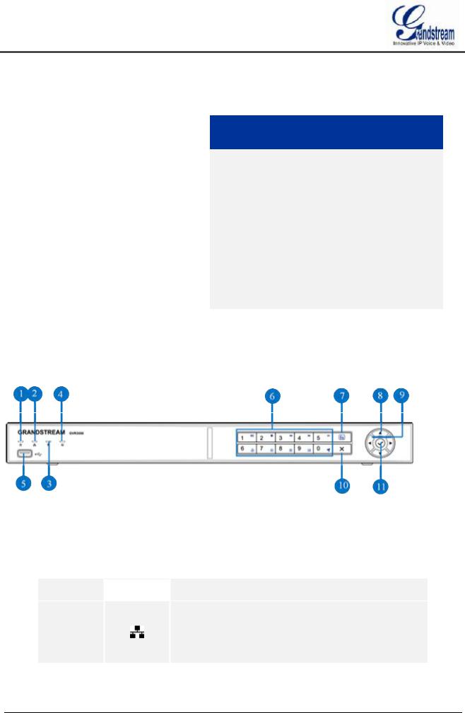
GVR3550 PRODUCT APPEARANCE
Figure 1 GVR3550 Front Panel
Table 4 GVR3550 Front Panel Buttons Explanation
No. |
|
Buttons |
|
Explanation |
|
|
|||
|
|
|
|
|
 Power indicator.
Network Indicator.
ŸDark: Abnormal network connection or has no access
|
to network |
ŸGreen: Normal network connection
ŸFlashing: Transmitting data...
GVR3550/GVR3552 User Manual |
Page 16 of 125 |
HDD Indicator.
Ÿ Solid green: HDD perfectly working
ŸFlashing: Reading data...
ŸNark: No HDD detected
|
|
|
|
|
|
Function Status Indicator. To indicate whether the |
|
|
|
|
|
|
|
||
|
|
|
|
|
|
numeric buttons are being used as functional button once |
|
|
|
|
|
|
|
pressed the function button. |
|
|
|
|
|
|
|
Ÿ |
Green: Functional status |
|
|
|
|
|
|
Ÿ |
Nark: Numerical status |
|
|
|
|
|
|
|
|
|
|
|
|
|
|
USB Interface. To connect to USB devices like mouse, |
|
|
|
|
|
|
keyboard and USB flash drive. |
||
|
|
|
|
|
|
||
|
|
|
|
|
|
|
|
|
|
|
|
|
|
Numeric Buttons. |
|
|
|
|
|
|
|
To input numbers and switch previews. |
|
|
|
|
|
|
|
Once pressed the function button, the numeric buttons will |
|
|
|
|
|
|
|
be used as functional buttons. |
|
|
|
|
|
|
|
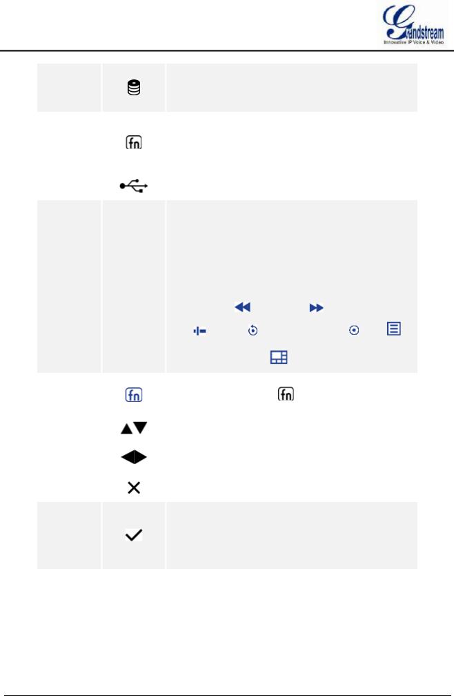
Number 0-9 are corresponding to the following functions: |
|
 Enable PTZ
 , Start/Pause
 , Stop
  ,
,
|
|
|
|
|
|
Fast Backward |
, Fast Forward , Single Frame |
|
|
|
|
|
|
|
Jump , Playback |
, Record Mode Setting , Menu , |
|
|
|
|
|
|
|
Switch preview windows |
, |
|
|
|
|
|
|
|
|
||
|
|
|
|
|
|
Function Button. To switch between numeric mode and |
||
|
|
|
|
|
|
function mode. The button |
indicates the status of the |
|
|
|
|
|
|
|
function button. |
|
|
|
|
|
|
|
|
|
||
|
|
|
|
|
|
Up and Down Navigation Buttons |
||
|
|
|
|
|
To switch among the activated controls |
|||
|
|
|
|
|
|
|||
|
|
|
|
|
|
|
||
|
|
|
|
|
|
Left and Right Navigation Buttons |
||
|
|
|
|
|
|
Ÿ To switch among the activated controls |
||
|
|
|
|
|
|
Ÿ Controls the progress bar when playback. |
||
|
|
|
|
|
|
|
|
|
|
|
|
|
|
|
Cancel Button |
|
|
|
|
|
|
|
Back to the previous menu or cancel operation. |
|||
|
|
|
|
|
|
|||
|
|
|
|
|
|
|
|
|
Confirm Button
ŸConfirm.
11Ÿ Switch to the default button.
ŸEnter menu.
ŸSelect a check box or enable toggle ON/OFF button. Pause/Resume auto patrol when auto patrol preview.
GVR3550/GVR3552 User Manual |
Page 17 of 125 |
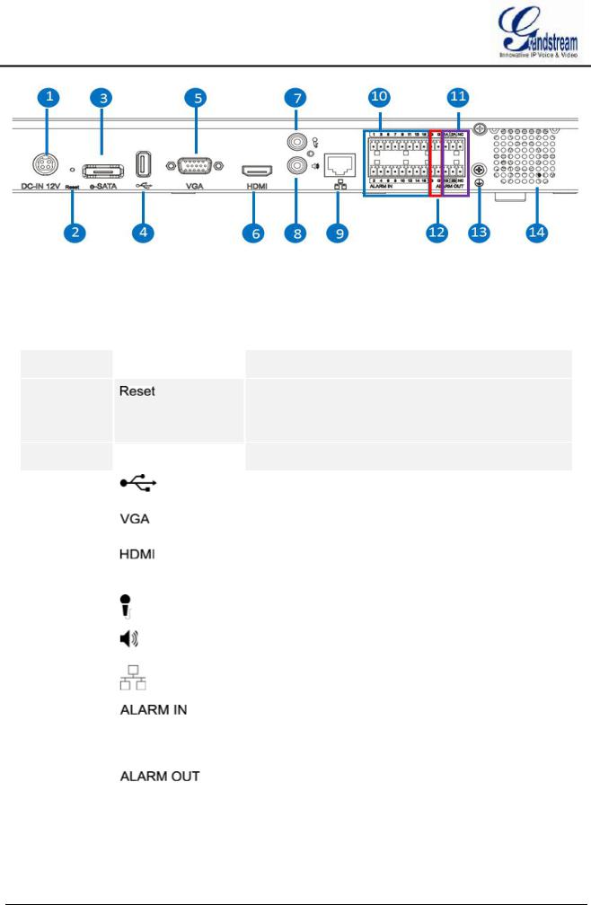
Figure 2 GVR3550 Back Panel
Table 5 GVR3552 Back Panel Buttons Explanation
Icon |
|
Buttons |
|
Explanation |
|
|
|
|
|
|
|
|
|
|
 Power Input. Input 12V DC
|
|
|
|
|
|
Reset Button. To reboot device or reset factory. |
ŸLong press for more than 10 seconds: factory reset
ŸPress when power on: reset when the GVR is abnormal
 eSATA Interface. To connect eSATA device
|
USB Interface. To connect to USB devices like mouse, |
|
keyboard and USB flash drive |
|
|
|
VGA Video Output. To output analog video signal, |
|
connecting to a monitor to view record |
|
|
|
HDMI. HD audio/video output interface, transmit |
|
uncompressed HD video and multichannel audio data to |
|
display device with HDMI interface |
|
|
|
Audio Input. Receiving analog audio signal from |
|
microphone, pickups and other devices |
|
|
|
Audio Output. Output analog audio signal to device like |
|
speaker |
|
|
|
Network Port. 10M/100M/1000M adaptive Ethernet |
|
interface |
|
|
|
Alarm Input Interfaces 1-16. |
|
16 alarm input interfaces receiving binary signals from |
|
external alarm sources like normally-closed alarm and |
|
normally-open alarm. |
|
|
11 |
Alarm Output Interfaces 1-2. |
|
2 set of alarm output interfaces, output alarm signal to |
|
external alarm device, power supply is required for external |
|
alarm device |
GVR3550/GVR3552 User Manual |
Page 18 of 125 |

12 |
-- |
Alarm Grounding. |
|
|
|
|
|
|
13 |
|
Grounding. |
|
|
|
|
|
|
14 |
|
FAN. For heat dissipation |
|
|
|
GVR3552 PRODUCT APPEARANCE
Table 6 GVR3552 Power Indicator Explanation
No. |
|
Buttons |
|
Explanation |
|
|
|||
|
|
|
|
|
 Power indicator.
Network Indicator.
ŸDark: Abnormal network connection or has no access
|
to network |
ŸGreen: Normal network connection
ŸFlashing: Transmitting data...
HDD Indicator.
Ÿ Solid green: HDD perfectly working
ŸFlashing: Reading data...
ŸNark: No HDD detected
|
|
|
Figure 3 GVR3552 Back Panel |
||
|
|
|
|
|
|
Icon |
|
Buttons |
|
|
Explanation |
|
|
|
|
|
|
|
|
|
|
|
|
|
|
POWER |
|
|
Power switch |
|
|
|
|
|
|
|
|
|
|
|
|
 Power Input. Input 12V DC
|
|
|
|
|
|
Reset Button. To reboot device or reset factory. |
ŸLong press for more than 10 seconds: factory reset
GVR3550/GVR3552 User Manual |
Page 19 of 125 |
ŸPress when power on: reset when the GVR is abnormal
 eSATA Interface. To connect eSATA device
|
|
USB Interface. To connect to USB devices like mouse, |
|
|
keyboard and USB flash drive |
|
|
|
|
|
VGA Video Output. To output analog video signal, |
|
|
connecting to a monitor to view record |
|
|
|
|
|
HDMI. HD audio/video output interface, transmit |
|
|
uncompressed HD video and multichannel audio data to |
|
|
display device with HDMI interface |
|
|
|
|
|
Audio Input. Receiving analog audio signal from |
|
|
microphone, pickups and other devices |
|
|
|
|
|
Audio Output. Output analog audio signal to device like |
|
|
speaker |
|
|
|
|
|
Network Port. 10M/100M/1000M adaptive Ethernet |
|
|
interface |
|
|
|
|
|
Alarm Input Interfaces 1-16. |
|
|
16 alarm input interfaces receiving binary signals from |
|
|
external alarm sources like normally-closed alarm and |
|
|
normally-open alarm. |
|
|
|
11 |
|
Alarm Output Interfaces 1-2. |
|
|
2 set of alarm output interfaces, output alarm signal to |
|
|
external alarm device, power supply is required for external |
|
|
alarm device |
|
|
|
12 |
-- |
Alarm Grounding. |
|
|
|
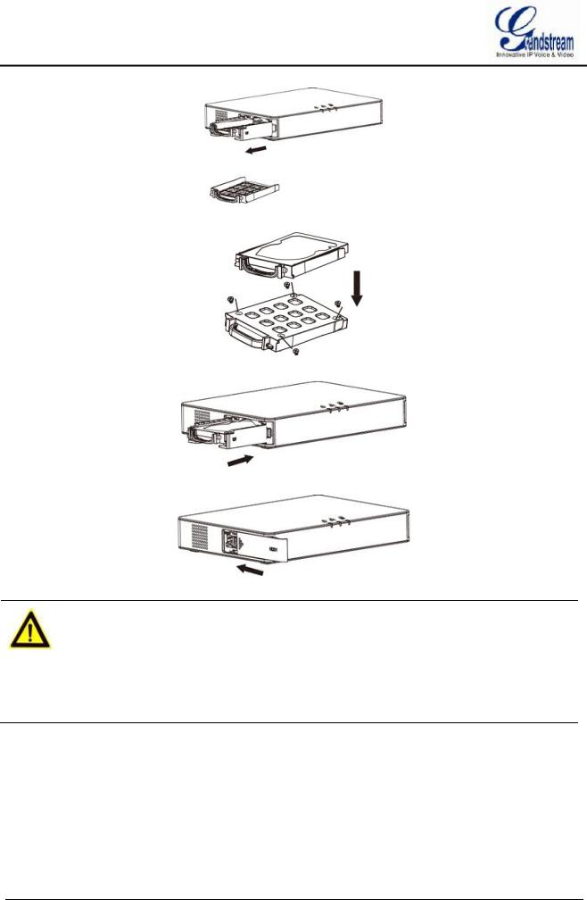
INSTALLING GVR3550 HDD
The GVR3550 contains no HDD with packaging, the first-time users need to check the device and install HDD. Please install the GVR3550 HDD according to the following procedures:
1.Twist four screws gently on the bottom of HDD, do not twist too tight;
2.Remove the fixed screws on the back and side panel of the main case, open the cover plate to find the HDD installing position;
3.Side put the main case, aims HDD with four screws on at the corresponding 4 screw holes on the baseplate and then twist the screws;
4.Repeat the previous steps to install other HDDs;
5.Connect HDD data lines and power cables to the interfaces of the mainboard;
6.Put the cover plate back and twist back the screws.
GVR3550/GVR3552 User Manual |
Page 20 of 125 |
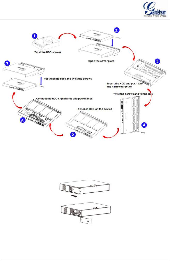
Figure 4 GVR3550 HDD Installation Diagram
INSTALLING GVR3552 HDD
Please install the GVR3552 HDD according to the following procedures:
1.Open the device by pushing forward the front panel cover of HDD;
2.Take out the HDD case;
GVR3550/GVR3552 User Manual |
Page 21 of 125 |
3.Put the 2.5" HDD into the HDD case in upright position then tighten the screws to install the HDD;
4.Push the HDD case into the slot in upright position until "click" sound heard;
5.Close the front cover panel;
6.Repeat the above steps to install 2nd HDD.
NOTE: Ø It is Recommended to use at least 7200rpm HDD or higher. Dedicated PC HDD is not recommendable. Unqualified HDD may unable to work properly.
ØGVR3550/GVR3552 does NOT support HDD hot swap. When GVR3550/GVR3552 is running, plug the HDD may cause fail to read /write HDD data or unable to identify the data. Grandstream will take no responsibility for the damage caused by wrong operations.
CONNECT GVR3550/GVR3552
Please connect the GVR3550/GVR3552 according to the following procedures:
1.Install the GVR3550/GVR3552 HDDs by following the steps in chapter Installing GVR3550/GVR3552 HDD;
GVR3550/GVR3552 User Manual |
Page 22 of 125 |

2.Plug in the network cables and connect the device to the display device;
3.Connect the mouse, keyboard, alarm input and output devices (optional);
4.Power up GVR3550/GVR3552 and the optional devices after connecting power cable;
5.The power indicator will be on if the GVR3550/GVR3552 is on, if all devices have been powered up successfully, the connection is done.
Figure 5 Connect GVR3550 Diagram
Figure 6 Connect GVR3552 Diagram
GVR3550/GVR3552 User Manual |
Page 23 of 125 |

NETWOKR CONNECTION
Users could log in the Web page with the administrator account after plugging in the network cable to GVR3550/GVR3552, go to Menu ->Status-> Network Status to view the network status like IP address and network sending/receiving rate. For details, please refer to the chapter Network Info.
EXTERNAL USB DEVICE
GVR3550/GVR3552 USB interface could be connected to mouse and keyboard, or a USB storage device.
NOTE: Ø The USB interface voltage on the front panel of the GVR3550 is a little higher than the one on the back panel, it is suggested that the USB interface on the back panel connect to mouse and keyboard while the one on the front panel connect to USB storage devices.
PLUG IN USB MOUSE/KEYBOARD
Users could check whether the mouse and keyboard are installed successful after plugging in them. The mouse or keyboard might be not compatible with GVR3550/GVR3552. If can't be detected, please replace the mouse or keyboard and try again.
When the USB mouse is plugged into GVR3550/GVR3552, users could make the following operations with the mouse.
Single click the left mouse:
·Access a functional menu.
·Select one option in a drop-down box.
·Confirm one operation like soft keyboard input after put the cursor in the input box.
·Bring out quick action bar when select preview screen.
Double click the left mouse:
·Switch between one window display in fullscreen and Multi-windows when preview.
·Save the alarm area and go back to the main menu.
Single click the right mouse:
·Bring up the shortcut menu in real-time monitoring mode.
·Go back to the preview screen on main menu or the playback screen.
·Save the alarm area and go back to the main menu.
Press the left mouse and drag:
·Drag one preview screen to another screen and switch their positions.
·Drag digital amplified area or alarm area.
·Drag the playback progress bar to set time point.
GVR3550/GVR3552 User Manual |
Page 24 of 125 |

·Drag the action box ( PTZ, Image config, Encoding Config) on preview screen.
NOTE: Ø If in a rare case that the mouse is not detected, the mouse might not compatible with the GVR3550, please replace the mouse.
PLUG IN USB STORAGE DEVICE
Users could click right mouse to check if there is "Uninstall" option in the menu after plugging in the USB device correctly. The option means the USB device is normal for use. Users could also go to Settings->System Settings->Basic System Settings, click "Refresh" button to check the USB device status.
INSTALLING eSATA
Plug in the eSATA cable to the corresponding interface on the back panel of GVR3550, power up eSATA or electrify it with USB cable (according to eSATA specific situation). Users could go to Settings->System Settings->HDD Management to view details like HDD Space, Free Space, HDD Status, HDD Type after installing eSATA. For details, please refer to the chapter HDD Management.
CONNECT HDMI MONITOR
Connect one end of the HDMI cable to the interface on the back panel of the GVR3550/GVR3552, and the other end to the corresponding interface of the HDMI monitor. Once powered up, users could see the preview screen of GVR3550/GVR3552 on HDMI monitor. GVR3550/GVR3552 can automatically adapt to HDMI monitor with 1080p and 720p resolution.
CONNECT VGA MONITOR
Connect one end of the VGA cable to the interface on the back panel of the GVR3550/GVR3552, and the other end to the corresponding interface of the VGA monitor. Once powered up, users could see the boot screen of GVR3550/GVR3552 on VGA monitor.
ØNOTE: Ø VGA does not support automatic resolution matching, users have to manual
set it.
ØThere is only one valid output when connect to VGA and HDMI monitor the same time. HDMI is valid while VGA is not by default.
ØHDMI supports automatic resolution matching with 1080p and 720p resolution only when set display to "auto".
ØWhen set display to "auto", if reboot GVR3550/GVR3552 without connecting to any displays, VGA output will be displayed by default. Connect to one HDMI display then reboot GVR if you want it to display HDMI output.
ØGo to System Settings->Display to set parameters.
GVR3550/GVR3552 User Manual |
Page 25 of 125 |
CONNECT ALARM DEVICE
Alarm input/output connection procedures are as follows:
1.Connect the alarm input device to the alarm input port;
2.Connect the alarm output device to the alarm output port;
3.Enter GVR3550 menu, configure alarm input/output parameters on Alarm Settings page. Alarm serial No.1 corresponds to the first alarm input on GVR3550 I/O interface, the following numbers keep to the same matching sequence. Set normally-opened alarm and normally-closed alarm according to the corresponding VIH /OV when alarm;
4.Set alarm output on Alarm Settings page. Alarm output 1 corresponds to the first alarm output; the following numbers keep to the same matching sequence.
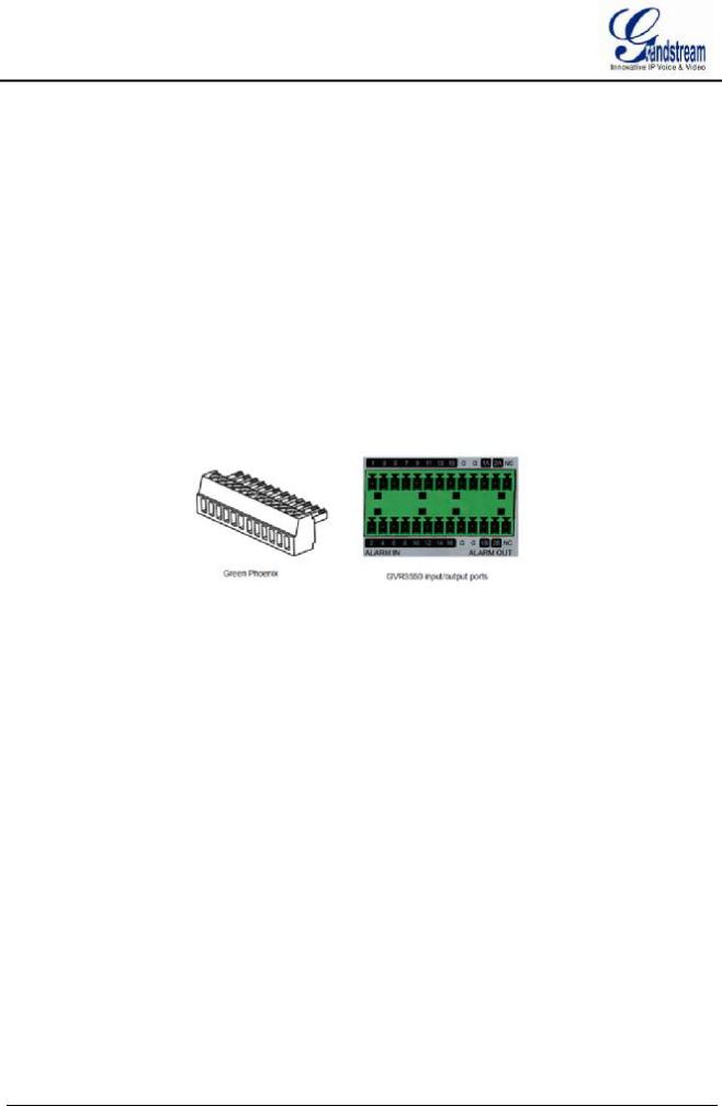
GVR alarm input/output ports on back panel could be connected to alarm input/output devices via the proprietary green phoenix.
Figure 7 Connect Input/Output Device With Phoenix
16 alarm input ports: One alarm input is consisting of one alarm input pin and one (public) G port.
2 set of alarm output ports: One alarm output is consisting of 1A and 1B, while 2A and 2B make the second alarm output.
Connect cables according to the port instruction on the back panel of GVR3550.
·Connect the first cable from alarm input device to ALARM IN 1, and the second cable to G port.
·Connect the first cable from alarm output device to ALARM OUT 1A, and the second cable to ALARM OUT 1B.
Connect other ports in the same way, see the connection diagram below.
GVR3550/GVR3552 User Manual |
Page 26 of 125 |
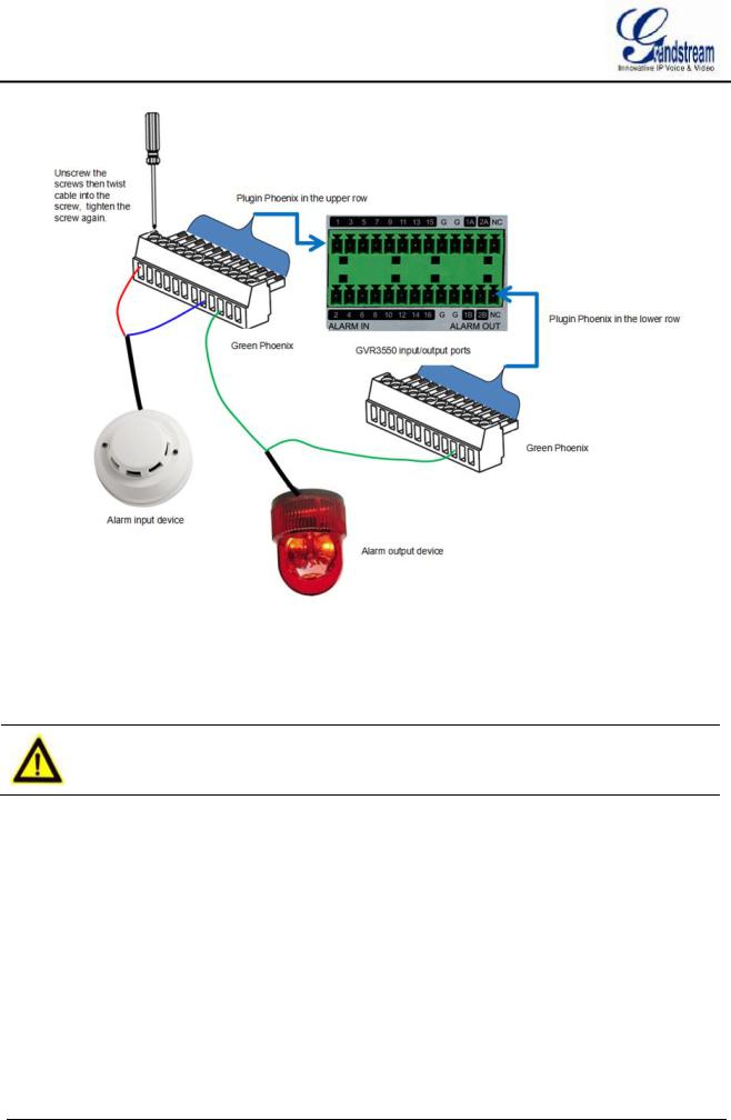
Figure 8 Alarm Device Connection Diagram
You need an external power source when connecting to an output device.
·Prepare a DC12V external voltage when need external DC power supply.
·Prepare an external relays when need external AC power supply, or it may destroy the device and there might be a potential security liability.
NOTE: Ø When power the alarm input device with an external power supply, the device should be common-grounded with GVR3550.
EXTERNAL INTERCOM DEVICE
GVR3550/GVR3552 supports web paging and local paging.
1.Connect the audio-input device like microphone or pickups with RCA interface to the audio input interface on the back panel of GVR;
2.Connect the audio-output device like speaker or stereo with RCA interface to the audio output interface on the back panel of GVR.
(The steps above ensure the GVR3550/GVR3552 could input or output audio);
3. Connect the microphone to PC audio input interface, while the earphone or stereo is being connected to
GVR3550/GVR3552 User Manual |
Page 27 of 125 |

PC audio output interface to make PC input/output audio.
Connect the audio input/output devices to the compatible cameras to input/output audio.
NOTE:
ØOnly supports RCA audio input/output devices.
GVR3550/GVR3552 User Manual |
Page 28 of 125 |

PRODUCT OVERVIEW
GVR3550/GVR3552 SPECIFICATIONS
Table 7 GVR3550/GVR3552 Software Specifications
Specification
Video
Recording
Recording
Rate
Recording
Mode
Audio
Compression
Audio
Recording
Video
Compression
Local Live
Preview
Playback
Trigger Event
Alarm
Intelligent
Search
Total Storage
RAID
Redundancy
GVR3550
Supports synchronous 24 cameras 720p (with 1280x720 resolution) record or 12 cameras 1080p (with 1920x1080 resolution) record
Supports up to 48 Mbps recording rate
Supports schedule record ,alarm record and manual record
G.711 a/u law
Synchronized Audio and Video recording
H.264 BP/MP/HP
4 cameras 720p or 2 cameras 1080p output simultaneously, 16 cameras VGA output, up to synchronous 24 cameras remote live preview
4 cameras simultaneous local and remote playback
Motion detection alarm, I/O alarm, event alarm and abnormal alarm
Time & date, recording type, cameras, tag
Grandstream customized
RAID 0 and RAID 1. It is recommend not to use more than 16 cameras when using RAID1
Supports record backup to USB external devices
GVR3552
Supports synchronous 16 cameras 720p (with 1280x720 resolution) record or 8 cameras 1080p (with 1920x1080 resolution) record
Supports up to 32 Mbps recording rate
Supports schedule record ,alarm record and manual record
G.711 a/u law
Synchronized Audio and Video recording
H.264 BP/MP/HP
4 cameras 720p or 2 cameras 1080p output simultaneously, VGA output, up to synchronous 24 cameras remote live preview
4 cameras simultaneous local and remote playback
Motion detection alarm, I/O alarm, event alarm and abnormal alarm
Time & date, recording type, cameras, tag
Grandstream customized
RAID 0 and RAID 1. It is recommend not to use more than 16 cameras when using RAID1
Supports record backup to USB external devices
GVR3550/GVR3552 User Manual |
Page 29 of 125 |
 Loading...