


Goodman ACNF180016AA, ACNF180516AA, ACNF180616AA, ACNF180816AA, ACNF240016AA INSTALLATION INSTRUCTIONS
...
CEILING MOUNT
AIR HANDLERS
INSTALLATION INSTRUCTIONS
IMPORTANT SAFETY INSTRUCTIONS
The following symbols and labels are used throughout this manual to indicate immediate or potential safety hazards. It is the owner’s and installer’s responsibility to read and comply with all safety information and instructions accompanying these symbols. Failure to heed safety information increases the risk of personal injury, property damage, and/or product damage.
HIGH VOLTAGE!
DISCONNECT ALL POWER BEFORE SERVICING OR INSTALLING THIS UNIT. MULTIPLE POWER SOURCES MAY BE PRESENT. FAILURE TO DO SO MAY CAUSE PROPERTY
DAMAGE, PERSONAL INJURY OR DEATH.
THE MANUFACTURER WILL NOT BE RESPONSIBLE FOR INJURY OR PROPERTY DAMAGE ARISING FROM IMPROPER SERVICE OR SERVICE PROCEDURES. IF YOU INSTALL OR PERFORM SERVICE ON THIS UNIT, YOU ASSUME RESPONSIBILITY FOR ANY PERSONAL INJURY OR PROPERTY DAMAGE WHICH MAY RESULT. MANY JURISDICTIONS REQUIRE A LICENSE TO INSTALL OR SERVICE HEATING AND AIR CONDITIONING EQUIPMENT.
INSTALLATION AND REPAIR OF THIS UNIT SHOULD BE PERFORMED ONLY BY INDIVIDUALS MEETING THE REQUIREMENTS OF AN “ENTRY LEVEL TECHNICIAN”, AT A MINIMUM, AS SPECIFIED BYTHE AIR CONDITIONING, HEATING, AND REFRIGERATION INSTITUTE (AHRI). ATTEMPTING TO INSTALL OR REPAIR THIS UNIT WITHOUT SUCH BACKGROUND MAY RESULT IN PRODUCT DAMAGE, PERSONAL INJURY, OR DEATH.
CO can cause serious illness including permanent brain |
|
damage or death. |
B10259-216 |
Advertencia especial para la instalación de calentadores ó manejadoras de aire en áreas cerradas como estacionamientos ó cuartos de servicio.
Las emisiones de monóxido de carbono pueden circular a través del aparato cuando se opera en cualquier modo.
El monóxido de carbono puede causar enfermedades severas como daño cerebral permanente ó muerte.
RISQUE D'EMPOISONNEMENT AU MONOXYDE DE CARBONE
Cette ventilation est nécessaire pour éviter le danger d'intoxication au CO pouvant survenir si un appareil produisant du monoxyde
de carbone continue de fonctionner au sein de la zone confinée.
B10259-216
IO-416E 12/2015
 CAUTION
HAVE YOUR CONTRACTOR IDENTIFY ALL THE VARIOUS CUTOFF SWITCHES AND DEVICES THAT SERVICE THIS UNIT. KNOW WHERE THE SWITCH IS THAT WILL CUT OFF ENERGY TO THE HEATING SYSTEM IN THE EVENT OF OVERHEATING.
SHIPPING INSPECTION
Upon receiving the product, inspect it for damage from shipment. Shipping damage, and subsequent investigation is the responsibility of the carrier. Verify the model number, specifications, electrical characteristics, and accessories are correct prior to installation. The distributor or manufacturer will not accept claims from dealers for transportation damage or installation of incorrectly shipped units.
CODES & REGULATIONS
This product is designed and manufactured to comply with national codes. Installation in accordance with such codes and/or prevailing local codes/regulations is the responsibility of the installer. The manufacturer assumes no responsibility for equipment installed in violation of any codes or regulations.
The United States Environmental Protection Agency (EPA) has issued various regulations regarding the introduction and disposal of refrigerants. Failure to follow these regulations may harm the environment and can lead to the imposition of substantial fines.
These regulations may vary by jurisdiction. A certified technician must perform the installation and service of this product. Should you have any questions please contact the local office of the EPA.
REPLACEMENT PARTS
When reporting shortages or damages, or ordering repair parts, give the complete product model and serial numbers as stamped on the product. Replacement parts for this product are available through your contractor or local distributor. For the location of your nearest distributor consult the white business pages, the yellow page section of the local telephone book or contact:
CONSUMER AFFAIRS
GOODMAN MANUFACTURING COMPANY, L.P.
7401 SECURITY WAY
HOUSTON, TEXAS 77040 (877) 254-4729
This ceiling mount air handler is available in cooling capacities of 1.5, 2 and 2.5 nominal tons of cooling with a PSC motor (ACNF18, ACNF24 and ACNF30) and 2 and 2.5 nominal tons of cooing with a constant torque (EEM) motor (ACNF25 and ACNF31). Electric heat models are available in capacities of 0, 5, 6, 8 and 10 kW.
The unit is designed to be installed in a horizontal position above a dropped ceiling. Do NOT install this unit outside the structure.
These models are designed for INDOOR USE ONLY.
PRE-INSTALLATION INSTRUCTIONS
Carefully read all instructions for the installation prior to installing product. Make sure each step or procedure is understood and any special considerations are taken into account before starting installation. Assemble all tools, hardware and supplies needed to complete the installation. Some items may need to be purchased locally. Make sure everything needed to install the product is on hand before starting.
Before attempting any installation, the following points should be considered:
•Structural strength of supporting members
•Clearances and provision for servicing
•Power supply and wiring
•Air duct connections
•Drain facilities and connections
InstallationClearances
Place this unit as close to the space to be air conditioned as possible. These units are U.L. listed for installations with zero clearance to combustible materials. If this unit is installed in a removable ceiling panel, ensure adequate space is available for servicing. Run ducts as direct as possible to supply and return outlets. Use non-flammable weatherproof flexible connectors on both supply and return connections at unit to reduce noise transmission.
Ducting
Duct work should be fabricated by the installing contractor in accordance with local codes. Use industry manuals such as such as NESCA (National Environmental Systems Contractors Association, 1501 Wilson Blvd., Arlington, Virginia 22209) as a guide when sizing and designing the duct system.
To ensure correct system performance, the ductwork is to be sized to accommodate 375-425 CFM per ton of cooling with the static pressure not to exceed 0.5” W.C. Inadequate ductwork that restricts airflow can result in improper performance and compressor or heater failure
APPLICATION INFORMATION
 CAUTION
HEAT PUMP PREMATURE FAILURE NOTICE
RUNNING THE UNIT WITHOUT HPSK-1 KIT INSTALLED ON HEAT PUMP CAN CAUSE PREMATURE UNIT FAILURE. A HPSK-1 KIT MUST BE INSTALLED
ON ALL HEAT PUMP APPLICATIONS.
TO PREVENT THE RISK OF PROPERTY DAMAGE, FIRE, CARBON MONOXIDE POISONING, EXPLOSION, PERSONAL INJURY, OR DEATH, DO NOT CONNECT DUCTWORK TO ANY HEAT PRODUCING DEVICE SUCH AS A FIREPLACE INSERT OR STOVE.
2
Filters
Filters are not provided with unit, and must be supplied and installed in the return air system by the installer. A field installed filter grille is recommended for easy and convenient access to the filters for periodic inspection and cleaning. Filters must have adequate face area for the rated air quantity of the unit. The minimum filter size is 20" x 20" x 1".
Condensate Drain Piping
The coil drain pan has a primary and a secondary drain with 3/4" NPT female connections. The connectors required are 3/4" NPT male, either PVC or metal pipe, and should be hand tightened to a torque of approximately 37 in-lbs. to prevent damage to the drain pan connection. An insertion depth between .355 to .485 inches (3-5 turns) should be expected at this torque. Use the female (3/4 NPT) threaded fitting that protrudes outside of the enclosure for external connections.
1.Ensure drain pan hole is NOT obstructed.
2.To prevent potential sweating and dripping on to finished space, it may be necessary to insulate the condensate drain line located inside the building. Use Armaflex® or similar material.
A Secondary Condensate Drain Connection has been provided for areas where the building codes require it. Pitch the drain line 1/ 4" per foot to provide free drainage. Insulate drain lines located inside the building to prevent sweating. Install a condensate trap to ensure proper drainage. If the secondary drain line is required, run the line separately from the primary drain and end it where it can be easily seen.
NOTE: Water coming from this line means the coil primary drain is plugged and needs clearing.
 CAUTION
IF SECONDARY DRAIN IS NOT INSTALLED, THE SECONDARY ACCESS MUST BE PLUGGED.
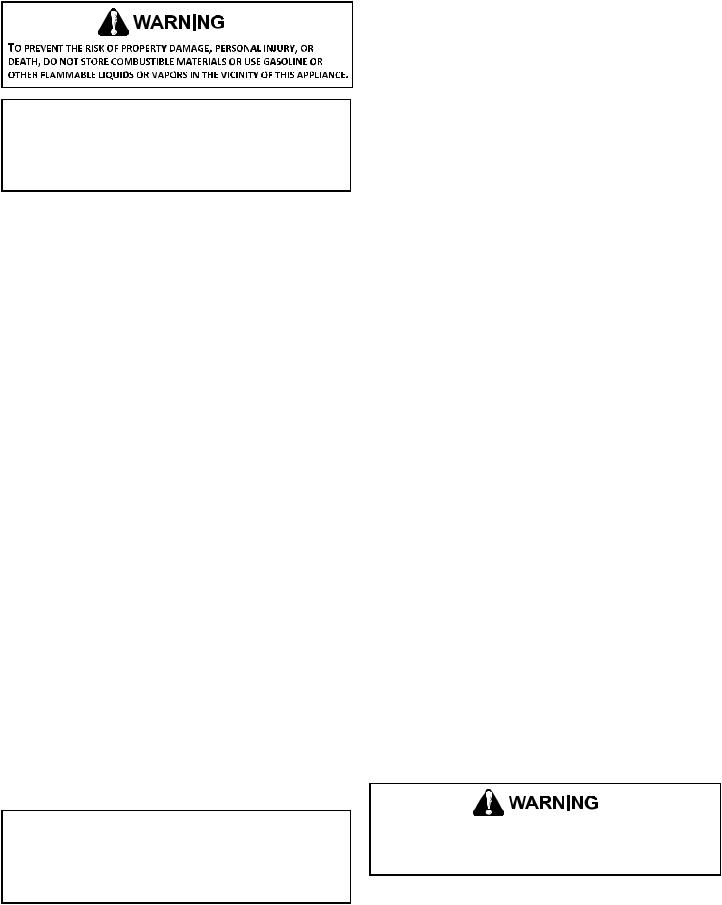
The installation must include a “P” style trap that is located as close as is practical to the evaporator coil. See Figure 1 for details of a typical condensate line “P” trap.
NOTE: Trapped lines are required by many local codes. In the absence of any prevailing local codes, please refer to the requirements listed in the Uniform Mechanical Building Code.
A drain trap in a draw-through application prevents air from being drawn back through the drain line during fan operation thus preventing condensate from draining, and if connected to a sewer line to prevent sewer gases from being drawn into the airstream during blower operation. In a blow-through application the drain trap prevents conditioned air from escaping. It is permissible in this application to use a shallow trap design sometimes referred to as a running trap.
Drain
Connection
|
2" MIN. |
Unit |
|
POSITIVE LIQUID SEAL |
3" MIN. |
REQUIRED AT TRAP |
Figure 1
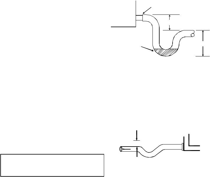
The depth of a running trap (Figure 2) should be either 1" or a depth that permits unrestricted condensate drainage without excessive air discharge.
Field experience has shown condensate drain traps with an open vertical Tee between the air handler and the condensate drain trap can improve condensate drainage in some applications, but may cause excessive air discharge out of the open Tee. We do not prohibit this type of drain but we also do not recommend it due to the resulting air leakage. Regardless of the condensate drain design used, it is the installer’s responsibility to ensure the condensate drain system is of sufficient design to ensure proper condensate removal from the coil drain pan.
Figure 2
When coils are installed above ceilings, or in other locations where damage from condensate overflow may occur, it is MANDATORY to install a field fabricated auxiliary drain pan under the coil cabinet enclosure. Drain lines from the auxiliary pan must be installed and terminated so that the homeowner can see water discharges. A primary condensate drain connection is located in the drain pan on the bottom of the coil / enclosure assembly. The female (3/4 fpt) threaded fitting that protrudes outside of the enclosure is used for external connections.
NOTE: Wire size based on 60°C rated wire insulation and 30°C Ambient Temp. (86°F).
For branch circuit wiring (main power supply to unit disconnect), determine the minimum wire size for the length of run from Table 1 using the circuit ampacity found on the unit rating plate. From the unit disconnect to unit, the smallest wire size allowable in Table 1 may be used, as long as the disconnect is in sight of the unit.
3
 Loading...