


Maxx Crosswalk 650
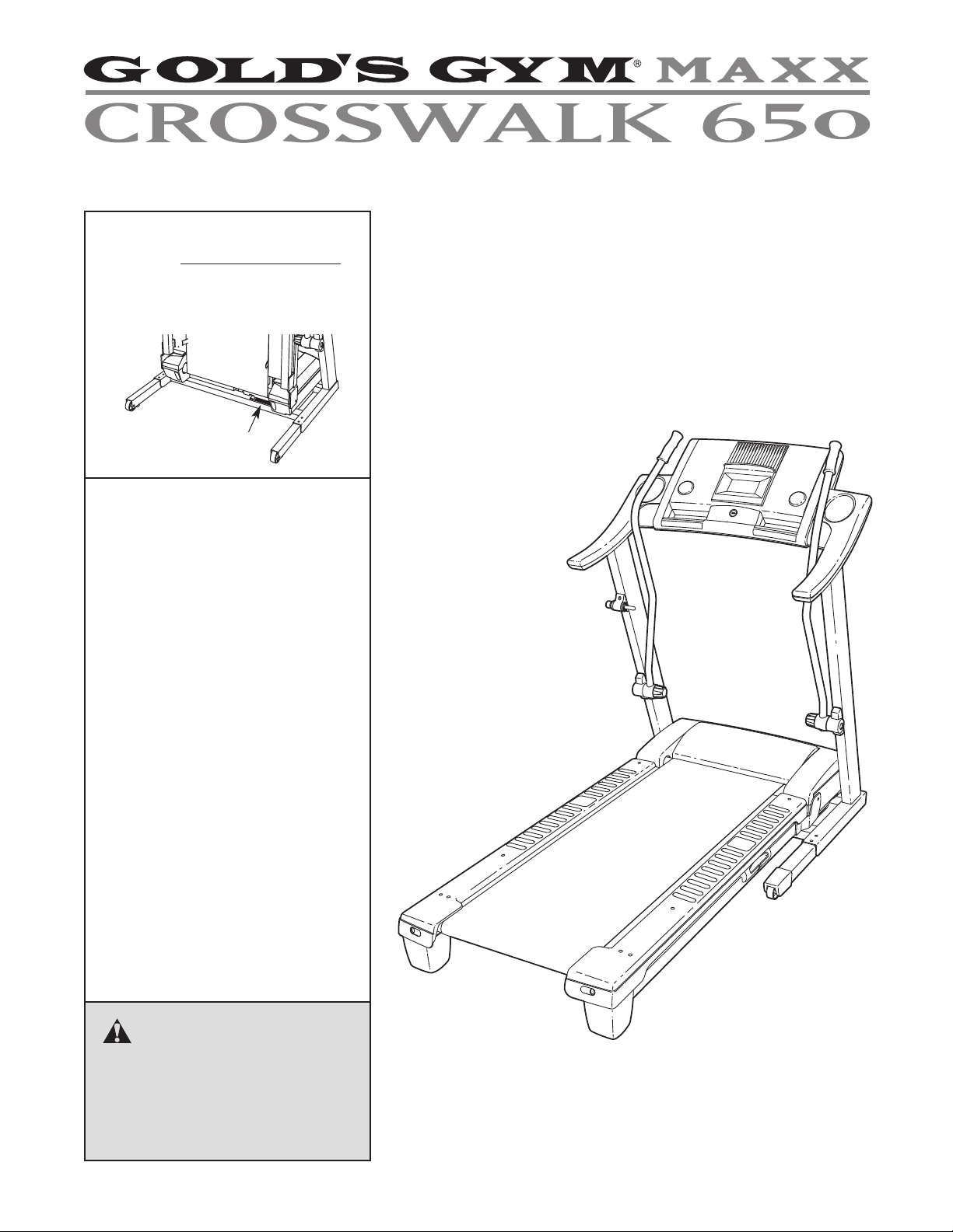
Model No. CWTL05607.2
Serial No.
Write the serial number in the space
above for future reference.
Serial Number Decal
QUESTIONS?
As a manufacturer, we are committed to providing complete customer
satisfaction. If you have questions,
or if parts are missing, PLEASE DO
NOT CONTACT THE STORE;
please contact Customer Care.
IMPORTANT: You must note the
product model number and
serial number (see the drawing
above) before contacting us:
USER'S MANUAL
CALL TOLL-FREE:
1-877-776-4777
Mon.–Fri. 6 a.m.–6 p.m. MST
Sat. 8 a.m.–4 p.m. MST
ON THE WEB:
www.goldsgympowerflex.com
CAUTION
Read all precautions and instructions in this manual before using
this equipment. Save this manual
for future reference.
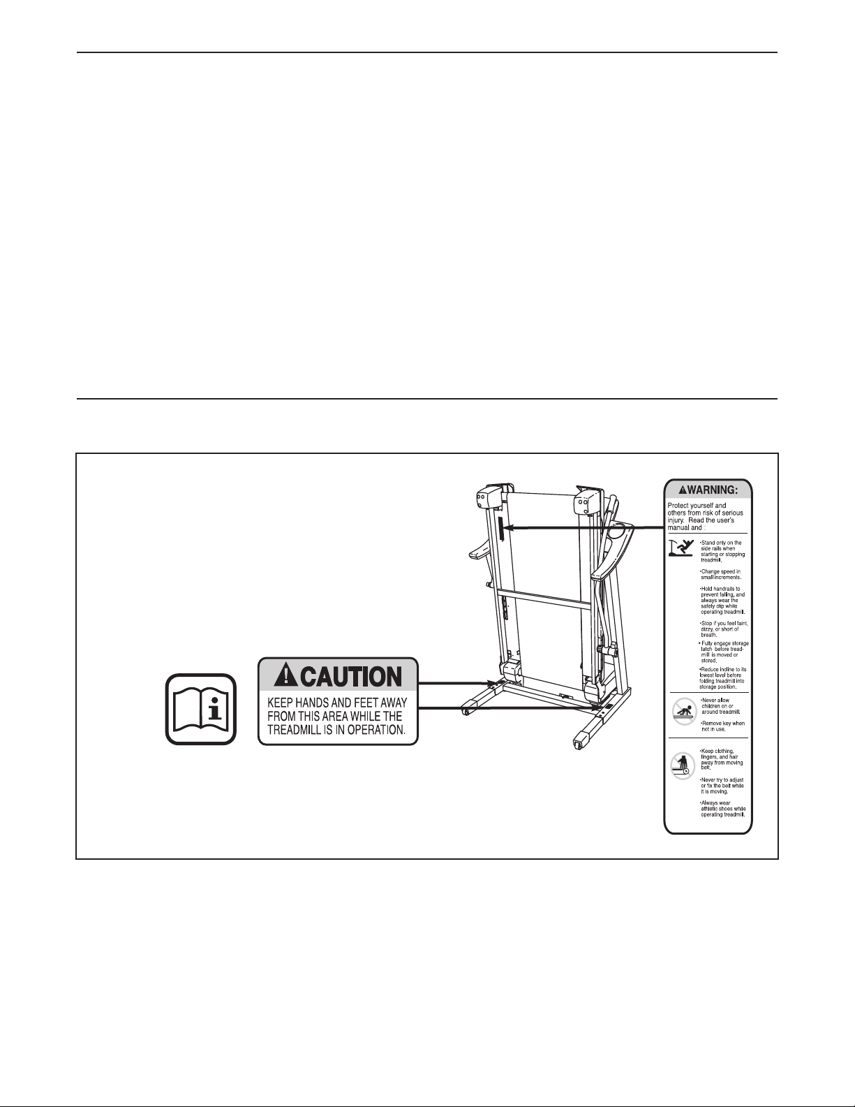
TABLE OF CONTENTS
WARNING DECAL PLACEMENT . . . . . . . . . . . . . . . . . . . . . . . . . . . . . . . . . . . . . . . . . . . . . . . . . . . . . . . . . . . . . .2
IMPORTANT PRECAUTIONS . . . . . . . . . . . . . . . . . . . . . . . . . . . . . . . . . . . . . . . . . . . . . . . . . . . . . . . . . . . . . . . .3
BEFORE YOU BEGIN . . . . . . . . . . . . . . . . . . . . . . . . . . . . . . . . . . . . . . . . . . . . . . . . . . . . . . . . . . . . . . . . . . . . . .5
SSEMBLY . . . . . . . . . . . . . . . . . . . . . . . . . . . . . . . . . . . . . . . . . . . . . . . . . . . . . . . . . . . . . . . . . . . . . . . . . . . . . . .6
A
OPERATION AND ADJUSTMENT . . . . . . . . . . . . . . . . . . . . . . . . . . . . . . . . . . . . . . . . . . . . . . . . . . . . . . . . . . . .11
HOW TO FOLD AND MOVE THE TREADMILL . . . . . . . . . . . . . . . . . . . . . . . . . . . . . . . . . . . . . . . . . . . . . . . . . .23
TROUBLESHOOTING . . . . . . . . . . . . . . . . . . . . . . . . . . . . . . . . . . . . . . . . . . . . . . . . . . . . . . . . . . . . . . . . . . . . .25
EXERCISE GUIDELINES . . . . . . . . . . . . . . . . . . . . . . . . . . . . . . . . . . . . . . . . . . . . . . . . . . . . . . . . . . . . . . . . . . .28
PART LIST . . . . . . . . . . . . . . . . . . . . . . . . . . . . . . . . . . . . . . . . . . . . . . . . . . . . . . . . . . . . . . . . . . . . . . . . . . . . . .30
EXPLODED DRAWING . . . . . . . . . . . . . . . . . . . . . . . . . . . . . . . . . . . . . . . . . . . . . . . . . . . . . . . . . . . . . . . . . . . .32
ORDERING REPLACEMENT PARTS . . . . . . . . . . . . . . . . . . . . . . . . . . . . . . . . . . . . . . . . . . . . . . . . . .Back Cover
LIMITED WARRANTY . . . . . . . . . . . . . . . . . . . . . . . . . . . . . . . . . . . . . . . . . . . . . . . . . . . . . . . . . . . . . .Back Cover
WARNING DECAL PLACEMENT
The decals shown here have been applied in the
locations shown. If a decal is missing or illegible,
call the telephone number on the front cover of
this manual and request a free replacement
decal. Apply the decal in the location shown.
Note: The decals may not be shown at actual size.
GOLD'S GYM is a registered trademark of Gold's Gym International, Inc. This product is manufactured and
distributed under license from Gold's Gym Merchandising, Inc.
2

IMPORTANT PRECAUTIONS
WARNING: To reduce the risk of serious injury, read all important precautions and in-
tructions in this manual and all warnings on your treadmill before using your treadmill. ICON as-
s
sumes no responsibility for personal injury or property damage sustained by or through the use of
this product.
1. Before beginning any exercise program, consult your physician. This is especially important for persons over the age of 35 or persons with pre-existing health problems.
2. It is the responsibility of the owner to ensure
that all users of this treadmill are adequately
informed of all warnings and precautions.
3. Use the treadmill only as described.
4. Place the treadmill on a level surface, with at
least 8 ft. (2.4 m) of clearance behind it and 2
ft. (0.6 m) on each side. Do not place the
treadmill on any surface that blocks air openings. To protect the floor or carpet from damage, place a mat under the treadmill.
5. Keep the treadmill indoors, away from moisture and dust. Do not put the treadmill in a
garage or covered patio, or near water.
6. Do not operate the treadmill where aerosol
products are used or where oxygen is being
administered.
7. Keep children under the age of 12 and pets
away from the treadmill at all times.
8. The treadmill should be used only by persons weighing 350 lbs. (159 kg) or less.
9. Never allow more than one person on the
treadmill at a time.
10. Wear appropriate exercise clothes when
using the treadmill. Do not wear loose
clothes that could become caught in the
treadmill. Athletic support clothes are recommended for both men and women. Always
wear athletic shoes. Never use the treadmill
with bare feet, wearing only stockings, or in
sandals.
11. When connecting the power cord (see page
11), plug the power cord into a surge suppressor (not included) and plug the surge
suppressor into a grounded circuit capable
of carrying 15 or more amps. No other appliance should be on the same circuit. Do not
use an extension cord.
12. Use only a single-outlet surge suppressor
that meets all of the specifications described
on page 11. To purchase a surge suppressor,
see your local GOLDʼS GYM dealer or call the
telephone number on the front cover of this
manual and order part number 146148, or see
your local electronics store.
13. Failure to use a properly functioning surge
suppressor could result in damage to the control system of the treadmill. If the control system is damaged, the walking belt may change
speed, accelerate, or stop unexpectedly,
which may result in a fall and serious injury.
14. Keep the power cord and the surge suppressor away from heated surfaces.
15. Never move the walking belt while the power
is turned off. Do not operate the treadmill if
the power cord or plug is damaged, or if the
treadmill is not working properly. (See TROUBLESHOOTING on page 25 if the treadmill is
not working properly.)
16. Read, understand, and test the emergency
stop procedure before using the treadmill (see
HOW TO TURN ON THE POWER on page 13).
17. Never start the treadmill while you are standing on the walking belt. Always hold the
handrails while using the treadmill.
18. The treadmill is capable of high speeds.
Adjust the speed in small increments to
avoid sudden jumps in speed.
19. The pulse sensor is not a medical device.
Various factors, including the user's movement, may affect the accuracy of heart rate
readings. The pulse sensor is intended only
as an exercise aid in determining heart rate
trends in general.
3

20. Never leave the treadmill unattended while it
is running. Always remove the key, unplug
the power cord, and switch the reset/off cir-
uit breaker to the off position when the
c
treadmill is not in use. (See the drawing on
age 5 for the location of the circuit breaker.)
p
21. Do not attempt to raise, lower, or move the
treadmill until it is properly assembled. (See
ASSEMBLY on page 6, and HOW TO FOLD
AND MOVE THE TREADMILL on page 23.)
You must be able to safely lift 45 lbs. (20 kg)
to raise, lower, or move the treadmill.
22. When folding or moving the treadmill, make
sure that the frame is held securely in the
storage position.
23. Inspect and properly tighten all parts of the
treadmill regularly.
SAVE THESE INSTRUCTIONS
24. Never insert any object into any opening on
the treadmill.
25.
DANGER: Always unplug the power
ord immediately after use, before cleaning the
c
treadmill, and before performing the maintenance and adjustment procedures described in
this manual. Never remove the motor hood unless instructed to do so by an authorized service representative. Servicing other than the
procedures in this manual should be performed
by an authorized service representative only.
26. This treadmill is intended for in-home use
only. Do not use this treadmill in a commercial, rental, or institutional setting.
4
BEFORE YOU BEGIN
Thank you for selecting the revolutionary GOLDʼS
®
GYM
MAXX CROSSWALK 650 treadmill. The MAXX
CROSSWALK 650 treadmill offers an impressive array
of features designed to make your workouts at home
more enjoyable and effective. And when youʼre not exercising, the unique MAXX CROSSWALK 650 treadmill
can be folded up, requiring less than half the floor
space of other treadmills.
For your benefit, read this manual carefully before
using the treadmill. If you have questions after read-
ing this manual, please see the front cover of this man-
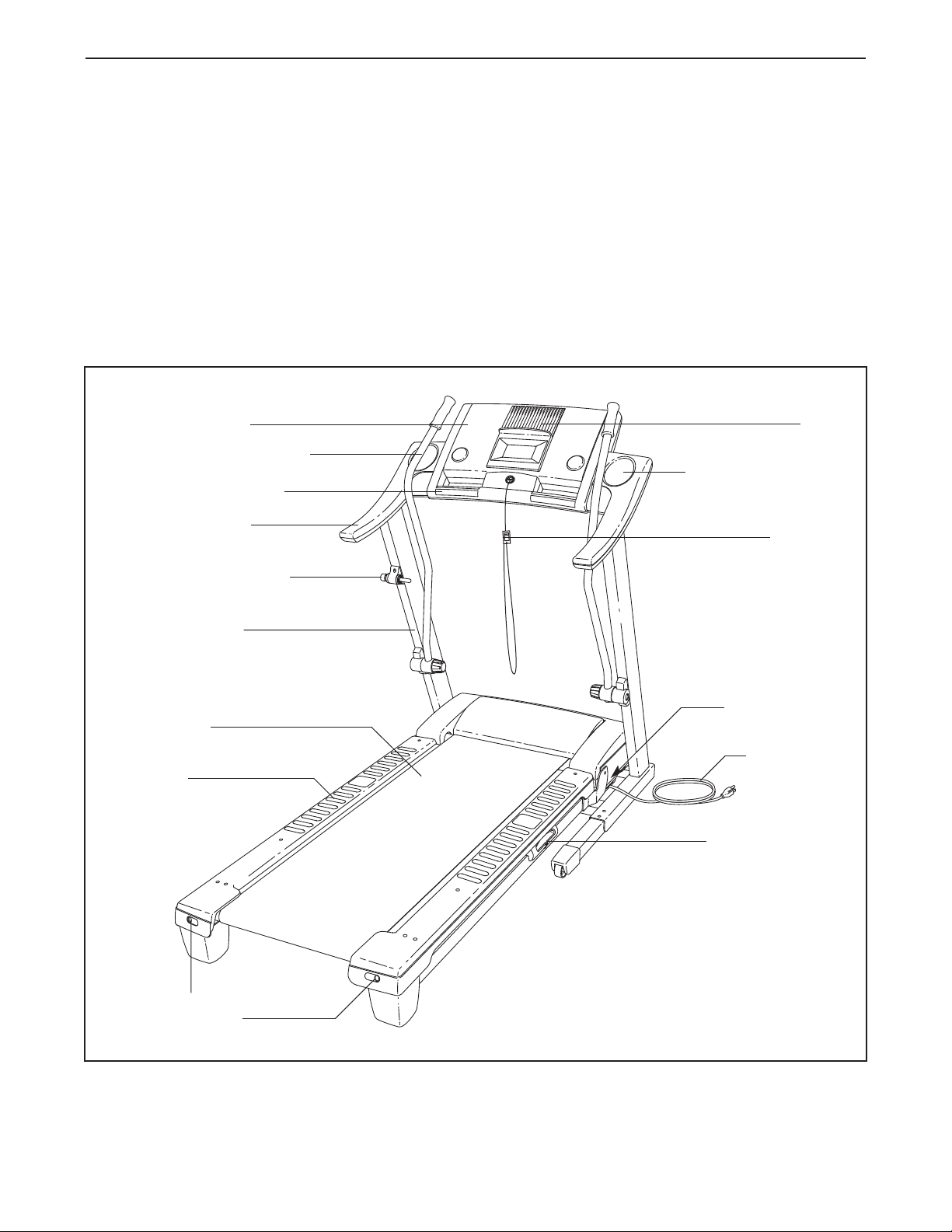
Console
Upper Body Arm
Pulse Sensor
Handrail
ual. To help us assist you, note the product model
number and serial number before contacting us. The
model number and the location of the serial number
decal are shown on the front cover of this manual.
To avoid a registration fee for any service needed
under warranty, you must register the treadmill at
www.iconservice.com/registration.
Before reading further, please review the drawing
below and familiarize yourself with the labeled parts.
Fan
*Water Bottle Holder
Key/Clip
Storage Latch
Upright
Walking Belt
Foot Rail
Rear Roller
Adjustment Bolts
Reset/Off
Circuit Breaker
Power Cord
Platform Cushion
*Water bottle is not included.
5
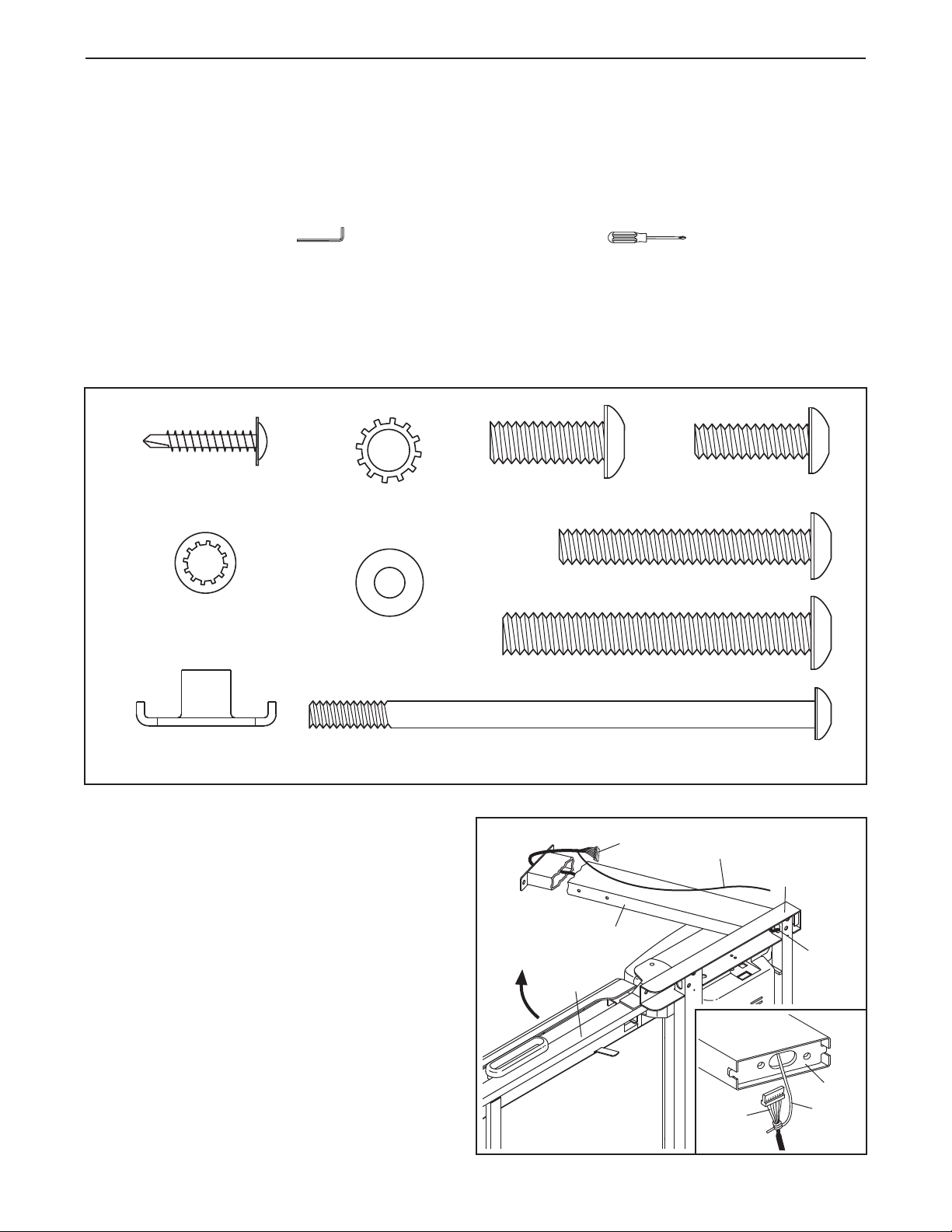
ASSEMBLY
#8 x 1" Tek Screw
(83)–4
Extension Leg Nut (67)–4
5/16" x 2 1/4" Bolt (65)–4
1/4" Flat Washer
(102)–4
1/4" x 4 1/2" Bolt (103)–4
3/8" Star
Washer (23)–8
3/8" x 2 3/4" Bolt (105)–2
5/16" x 1" Bolt (64)–4
3/8" x 1" Bolt
(106)–2
5/16" Star Washer
(8)–4
To hire an authorized service technician to assemble the treadmill, call 1-800-445-2480. Assembly requires two persons. Set the treadmill in a cleared area and remove all packing materials. Do not dispose of
the packing materials until assembly is completed. Note: The underside of the treadmill walking belt is coated
ith high-performance lubricant. During shipping, lubricant may be transferred to the top of the walking belt or the
w
shipping carton. This is a normal condition and does not affect treadmill performance. If there is lubricant on top
of the walking belt, simply wipe off the lubricant with a soft cloth and a mild, non-abrasive cleaner. Assembly re-
quires the included hex key and your own Phillips screwdriver .
Use the drawings below to identify the assembly hardware. The number in parentheses below each drawing is
the key number of the part, from the PART LIST near the end of this manual. The number after the parentheses
is the quantity needed for assembly. Note: If a part is not in the parts bag, check to see if it is preattached to
one of the parts to be assembled. Extra hardware may be included. To avoid damaging plastic parts, do
not use power tools for assembly.
1. Make sure that the power cord is unplugged.
With the help of a second person, carefully tip
the treadmill onto its left side. Partially fold the
Frame (58) so that the treadmill is more stable;
do not fully fold the Frame yet.
Identify the Right Upright (107), and hold it near
the Base (108) at the angle shown.
See the inset drawing. Tie the wire tie in the
Right Upright (107) securely around the end of
the Upright Wire (77). Then, pull the other end
of the wire tie until the Upright Wire is routed
completely through the Right Upright. Make
sure that the Upright Wire does not fall into
the Right Upright.
1
58
6
77
107
Wire Tie
77
108
77
107
Wire
Tie
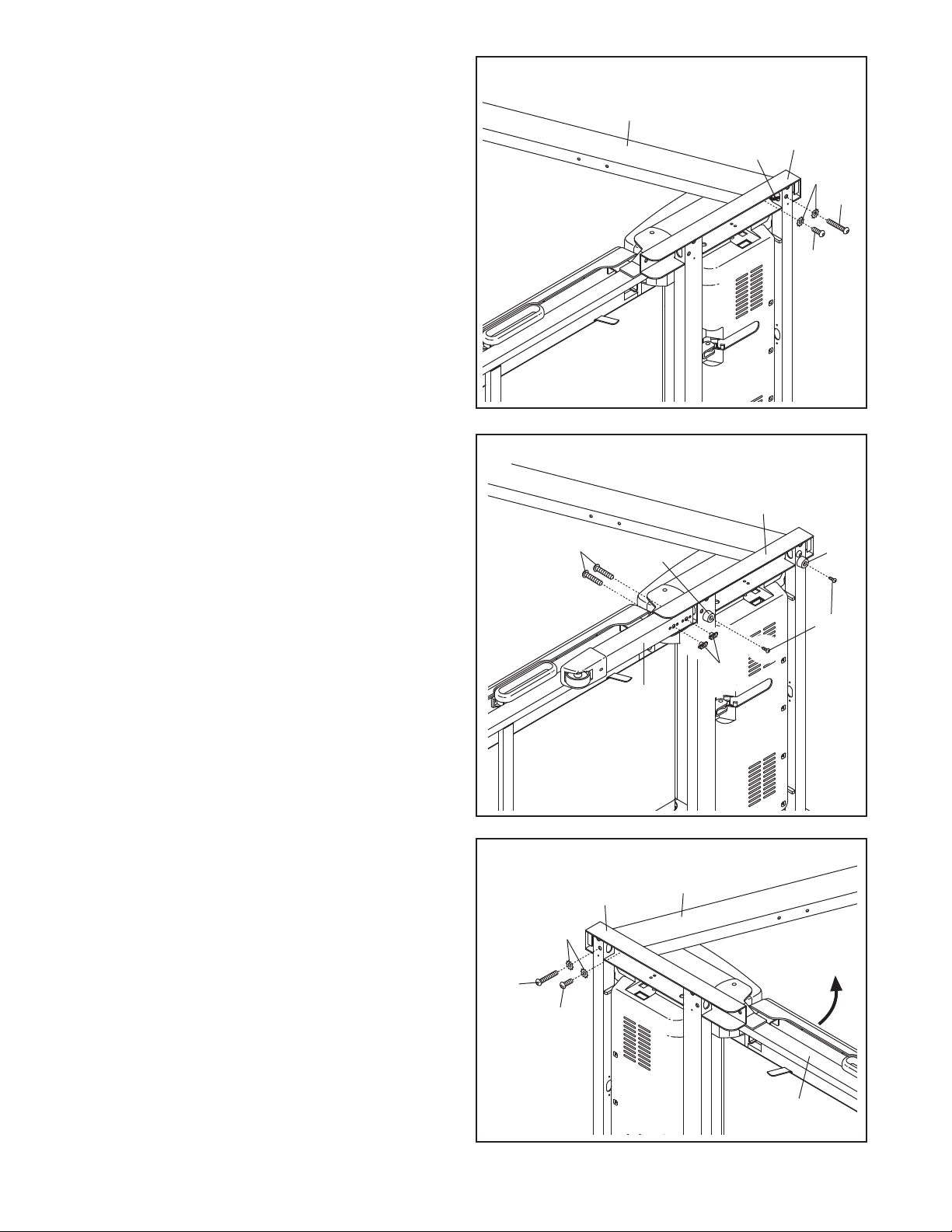
2. Hold the Right Upright (107) against the Base
(108). Be careful not to pinch the Upright
Wire (77).
Attach the Right Upright (107) to the Base (108)
ith a 3/8" x 1" Bolt (106), a 3/8" x 2 3/4" Bolt
w
(105), and two 3/8" Star Washers (23). Do not
tighten the Bolts yet.
2
107
08
1
7
7
23
105
106
3. Attach two Base Pads (82) to the Base (108)
with two #8 x 1" Tek Screws (83) as shown.
Insert an Extension Leg (89) into the Base (108)
as shown. Hold two Extension Leg Nuts (67) in
the bottom of the Extension Leg. Next, insert
two 5/16" x 2 1/4" Bolts (65) into the top of the
Extension Leg, and firmly tighten the Bolts into
the Extension Leg Nuts.
4. With the help of a second person, carefully tip
the treadmill onto its other side. Partially fold the
Frame (58) so that the treadmill is more stable.
Do not fully fold the Frame yet.
3
108
65
4
108
82
67
89
84
82
83
Attach the Left Upright (84) to the Base (108)
with a 3/8" x 1" Bolt (106), a 3/8" x 2 3/4" Bolt
(105), and two 3/8" Star Washers (23). Do not
tighten the Bolts yet.
23
105
106
58
7
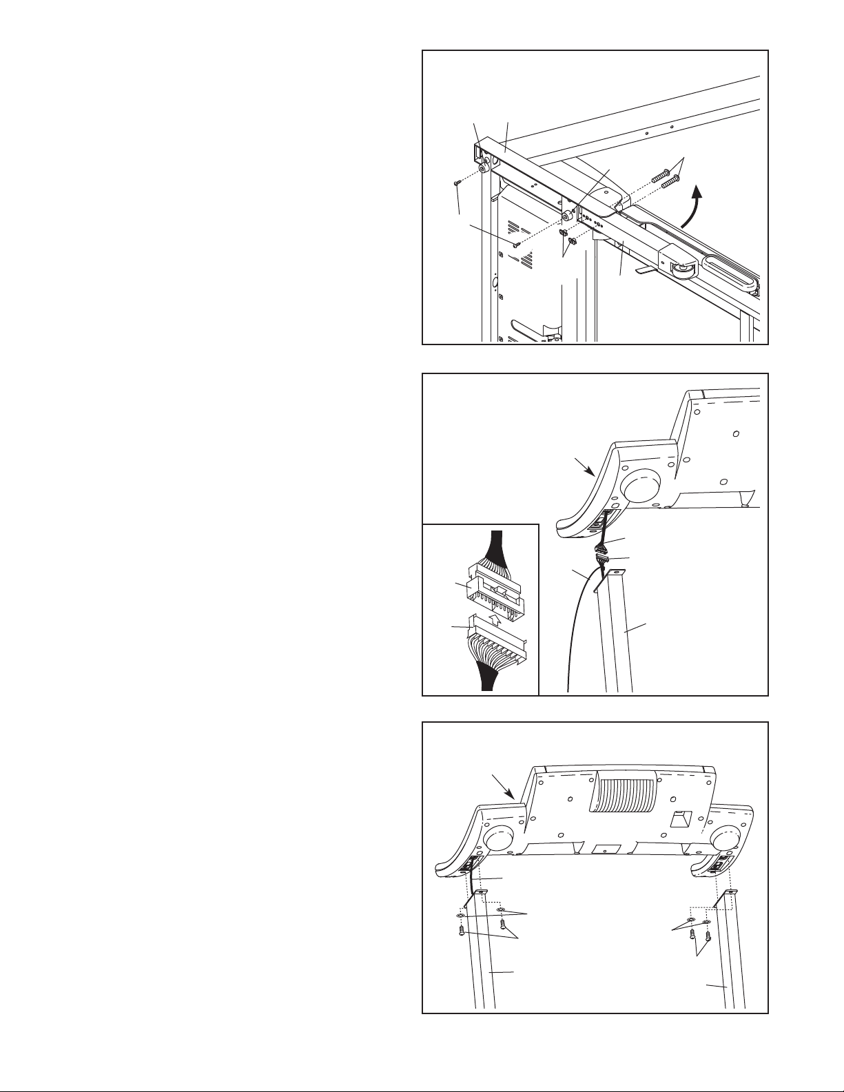
5. Attach two Base Pads (82) to the Base (108)
with two #8 x 1" Tek Screws (83) as shown.
nsert the other Extension Leg (89) into the
I
Base (108) as shown. Hold two Extension Leg
uts (67) in the bottom of the Extension Leg.
N
Next, insert two 5/16" x 2 1/4" Bolts (65) into the
top of the Extension Leg, and firmly tighten the
Bolts into the Extension Leg Nuts.
5
108
2
8
82
83
67
89
65
6. With the help of a second person, carefully raise
the Right Upright (107) and the Left Upright (not
shown) to a vertical position.
Have the second person hold the console assembly near the Right Upright (107) as shown.
Look under the console assembly and locate
the Console Wire (66).
Connect the Upright Wire (77) to the Console
Wire (66). See the inset drawing. The connec-
tors should slide together easily and snap
into place. If they do not, turn one connector
and try again. IF THE CONNECTORS ARE
NOT CONNECTED PROPERLY, THE CONSOLE MAY BE DAMAGED WHEN THE
POWER IS TURNED ON. Remove the wire tie
from the Upright Wire.
7. Insert the Upright Wire (77) and the Console
Wire (66) into the Right Upright (107).
Set the console assembly on the Uprights (84,
107). Be careful not to pinch the wires. While
a second person holds the console assembly,
attach it with four 5/16" x 1" Bolts (64) and four
5/16" Star Washers (8); start all four Bolts and
then firmly tighten them.
Plug in the power cord as described on page
11, and turn on the power as described on page
13. (Note: The treadmill may automatically rise
to the maximum incline level and then return to
the minimum level.) Adjust the incline to the lowest incline level as described in step 4 on page
14.
6
66
77
7
Console
Assembly
Console
Assembly
77, 66
8
64
107
Wire
Tie
66
77
107
8
64
84
8
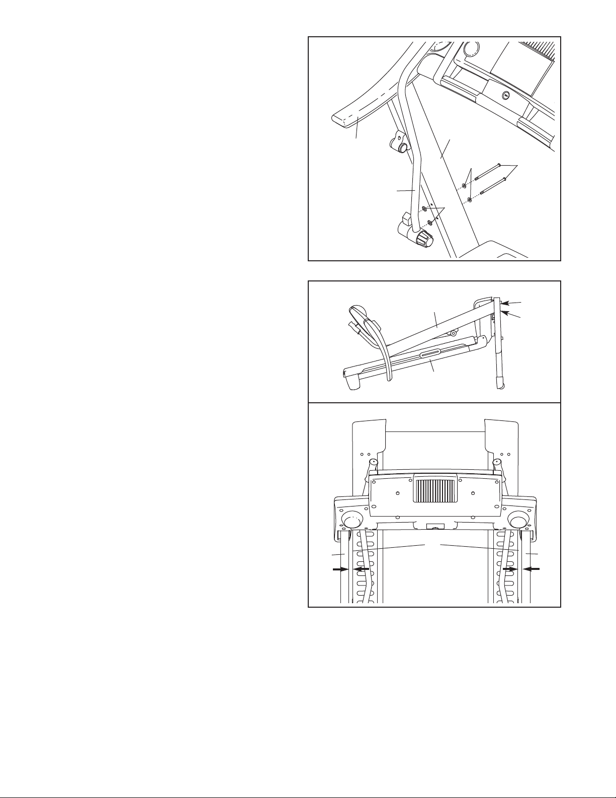
8. Attach the Left Upper Body Arm (97) to the Left
Upright (84) with two 1/4" x 4 1/2" Bolts (103),
two 1/4" Flat Washers (102), and two 3/8" Star
Washers (23) as shown. Make sure that the
eft Upper Body Arm is on the indicated side
L
of the Left Handrail (13).
8
Attach the Right Upper Body Arm (not
shown) to the Right Upright (not shown) in
the same way.
9. With the help of a second person, carefully
lower the Left and Right Uprights (84, 107) to
the position shown.
See the lower drawing. Position the Uprights
(84, 107) so that the treadmill Frame (58) is
centered between the Uprights.
Firmly tighten the two 3/8" x 1" Bolts (106) and
the two 3/8" x 2 3/4" Bolts (105). Be careful not
to overtighten the Bolts.
84
13
102
97
23
9
84, 107
58
103
105
106
With the help of a second person, carefully raise
the Uprights (84, 107).
107
Top View
58
84
9
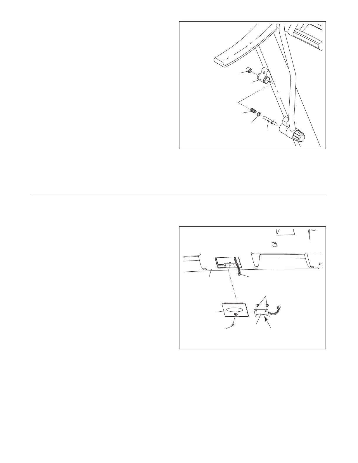
10. Remove the knob from the pin. Make sure that
the collar and the spring are on the pin. (Note: If
there are two collars, place one on each side of
he spring.) Next, insert the pin into the Latch
t
Housing (73). Then, tighten the knob onto the
in.
p
11. Make sure that all parts are properly tightened before you use the treadmill. If there are sheets of clear
plastic on the treadmill decals, remove the plastic. To protect the floor or carpet, place a mat under the treadmill. Note: Extra hardware may be included. Keep the included hex key in a secure place; the hex key is used
to adjust the walking belt (see pages 26 and 27).
10
Knob
73
Spring
Collar
Pin
If you purchase the optional chest pulse sensor (see page 21), follow the steps below to install the receiver
included with the chest pulse sensor.
1. Remove the key from the console and unplug
the power cord.
Remove the indicated #8 x 3/4" Screw (3) and
the Access Door (76) from the back of the
Console Base (85).
2. Connect the wire on the receiver (A) to the indi-
cated wire extending from the Console Base
(85). Hold the receiver so that the small cylin-
der is oriented as shown and is facing the
Console Base. Attach the receiver to the plastic
posts on the Access Door (76) with the two included small screws.
3. Make sure that no wires are pinched. Reattach
the Access Door (76) with the #8 x 3/4" Screw
(3). Discard the other wires included with the receiver.
85
76
3
Wire
Small
Screws
A
Small
Cylinder
10
OPERATION AND ADJUSTMENT
HE PRE-LUBRICATED WALKING BELT
T
Your treadmill features a walking belt coated with highperformance lubricant. IMPORTANT: Never apply sil-
cone spray or other substances to the walking
i
belt or the walking platform. Such substances will
deteriorate the walking belt and cause excessive
wear.
ric shock. This product is equipped with a cord having
t
an equipment-grounding conductor and a grounding
plug. Plug the power cord into a surge suppressor,
and plug the surge suppressor into an appropriate
utlet that is properly installed and grounded in
o
accordance with all local codes and ordinances.
Important: The treadmill is not compatible with
GFCI-equipped outlets.
HOW TO PLUG IN THE POWER CORD
DANGER: Improper connection
of the equipment-grounding conductor can
result in an increased risk of electric shock.
Check with a qualified electrician or serviceman if you are in doubt as to whether the
product is properly grounded. Do not modify
the plug provided with the product—if it will
not fit the outlet, have a proper outlet
installed by a qualified electrician.
Your treadmill, like any other type of sophisticated
electronic equipment, can be seriously damaged by
sudden voltage changes in your homeʼs power.
Voltage surges, spikes, and noise interference can
result from weather conditions or from other appliances
being turned on or off. To decrease the possibility of
the treadmill being damaged, always use a surge
suppressor with the treadmill (see drawing 1 at the
right). To purchase a surge suppressor, see your
local GOLDʼS GYM dealer or call the telephone
number on the front cover of this manual and order
part number 146148, or see your local electronics
store.
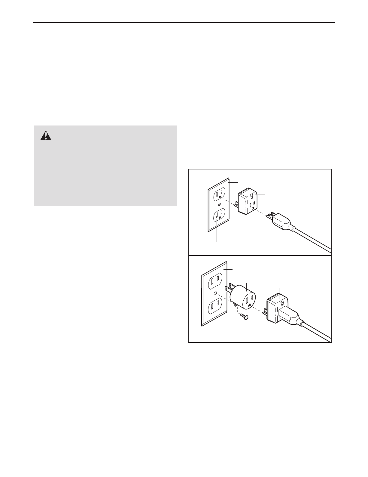
This product is for use on a nominal 120-volt circuit,
and has a grounding plug that looks like the plug illustrated in drawing 1 below. A temporary adapter that
looks like the adapter illustrated in drawing 2 may be
used to connect the surge suppressor to a 2-pole
receptacle as shown in drawing 2 if a properly
grounded outlet is not available.
1
Grounded Outlet Box
Surge Suppressor
Grounding Pin
Grounding Pin
Grounded Outlet
2
Grounded Outlet Box
Adapter
Grounding Plug
Surge Suppressor
Use only a single-outlet surge suppressor that is
UL 1449 listed as a transient voltage surge suppressor (TVSS). The surge suppressor must have a
UL suppressed voltage rating of 400 volts or less
and a minimum surge dissipation of 450 joules.
The surge suppressor must be electrically rated for
120 volts AC and 15 amps. There must be a monitoring light on the surge suppressor to indicate
whether it is functioning properly. Failure to use a
properly functioning surge suppressor could result
in damage to the control system of the treadmill. If
the control system is damaged, the walking belt
may change speed, accelerate or stop unexpectedly, which may result in a fall and serious injury.
This product must be grounded. If it should malfunc-
tion or break down, grounding provides a path of least
resistance for electric current to reduce the risk of elec-
Lug
Metal Screw
The temporary adapter should be used only until a
properly grounded outlet (drawing 1) can be installed
by a qualified electrician.
The green-colored rigid ear, lug, or the like extending
from the adapter must be connected to a permanent
ground such as a properly grounded outlet box cover.
Whenever the adapter is used it must be held in place
by a metal screw. Some 2-pole receptacle outlet box
covers are not grounded. Contact a qualified electrician to determine if the outlet box cover is
grounded before using an adapter.
11
 Loading...