


SERVICE STATION MANUAL
664841(IT)-664842(EN)-664843(FR)-664844 (DE)-664845(ES)-664846(PT)-664847(NL)-664848 (EL)
GP 800 i.e.

SERVICE STATION
MANUAL
GP 800 i.e.
The descriptions and illustrations given in this publication are not binding. While the basic features as described and illustrated in this manual remain unchanged, PIAGGIO - GILERA reserves the right, at any time and without being required to update this publication beforehand, to make any changes to components, parts or accessory supplies, which it considers necessary to improve the product or which are required for manufacturing or construction reasons.
Not all versions shown in this publication are available in all Countries. The availability of individual versions should be confirmed with the official Piaggio sales network.
"© Copyright 2007 - PIAGGIO & C. S.p.A. Pontedera. All rights reserved. Reproduction of this publication in whole or in part is prohibited."
PIAGGIO & C. S.p.A. - After-Sales
V.le Rinaldo Piaggio, 23 - 56025 PONTEDERA (Pi)

SERVICE STATION MANUAL
GP 800 i.e.
This service station manual has been drawn up by Piaggio & C. Spa to be used by the workshops of Piaggio-Gilera dealers. It is assumed that the user of this manual for maintaining and repairing Piaggio vehicles has a basic knowledge of mechanical principles and vehicle repair technique procedures. Any significant changes to vehicle characteristics or to specific repair operations will be communicated by updates to this manual. Nevertheless, no mounting work can be satisfactory if the necessary equipment and tools are unavailable. It is therefore advisable to read the sections of this manual concerning special tools, along with the special tool catalogue.
N.B. Provides key information to make the procedure easier to understand and carry out.
CAUTION Refers to specific procedures to carry out for preventing damages to the vehicle.
WARNING Refers to specific procedures to carry out to prevent injuries to the repairer.
Personal safety Failure to completely observe these instructions will result in serious risk of personal injury.
Safeguarding the environment Sections marked with this symbol indicate the correct use of the vehicle to prevent damaging the environment.
Vehicle intactness The incomplete or non-observance of these regulations leads to the risk of serious damage to the vehicle and sometimes even the invalidity of the guarantee.


INDEX OF TOPICS
CHARACTERISTICS |
CHAR |
|
|
|
|
TOOLING |
TOOL |
|
|
|
|
MAINTENANCE |
MAIN |
|
|
|
|
TROUBLESHOOTING |
TROUBL |
|
|
|
|
ELECTRICAL SYSTEM |
ELE SYS |
|
|
|
|
ENGINE FROM VEHICLE |
ENG VE |
|
|
|
|
ENGINE |
ENG |
|
|
|
|
INJECTION |
INJEC |
|
|
|
|
SUSPENSIONS |
SUSP |
|
|
|
|
BRAKING SYSTEM |
BRAK SYS |
|
|
|
|
COOLING SYSTEM |
COOL SYS |
|
|
|
|
CHASSIS |
CHAS |
|
|
|
|
PRE-DELIVERY |
PRE DE |
|
|
|
|
TIME |
TIME |
|
|

INDEX OF TOPICS
CHARACTERISTICS |
CHAR |

Characteristics |
GP 800 i.e. |
|
|
This section describes the general specifications of the vehicle.
Rules
This section describes general safety rules for any maintenance operations performed on the vehicle.
Safety rules
-If work can only be done on the vehicle with the engine running, make sure that the premises are wellventilated, using special extractors if necessary; never let the engine run in an enclosed area. Exhaust fumes are toxic.
-The battery electrolyte contains sulphuric acid. Protect your eyes, clothes and skin. Sulphuric acid is highly corrosive; in the event of contact with your eyes or skin, rinse thoroughly with abundant water and seek immediate medical attention.
-The battery produces hydrogen, a gas that can be highly explosive. Do not smoke and avoid sparks or flames near the battery, especially when charging it.
-Fuel is highly flammable and it can be explosive given some conditions. Do not smoke in the working area, and avoid open flames or sparks.
-Clean the brake pads in a well-ventilated area, directing the jet of compressed air in such a way that you do not breathe in the dust produced by the wear of the friction material. Even though the latter contains no asbestos, inhaling dust is harmful.
Maintenance rules
-Use original PIAGGIO spare parts and lubricants recommended by the Manufacturer. Non-original or non-conforming spares may damage the vehicle.
-Use only the appropriate tools designed for this vehicle.
-Always use new gaskets, sealing rings and split pins upon refitting.
-After removal, clean the components using non-flammable or low flash-point solvent. Lubricate all the work surfaces except the tapered couplings before refitting.
-After refitting, make sure that all the components have been installed correctly and work properly.
-For removal, overhaul and refit operations use only tools with metric measures. Metric bolts, nuts and screws are not interchangeable with coupling members with English measurement. Using unsuitable coupling members and tools may damage the scooter.
-When carrying out maintenance operations on the vehicle that involve the electrical system, make sure the electric connections have been made properly, particularly the ground and battery connections.
CHAR - 2

GP 800 i.e. |
Characteristics |
|
|
Vehicle identification
Chassis prefix (A):
ZAPM55100
Engine prefix (B):
M554M
Dimensions and mass
CHAR - 3

Characteristics |
GP 800 i.e. |
|
|
WEIGHTS AND DIMENSIONS
|
Specification |
Desc./Quantity |
|
|
Kerb weight |
248 ± 10 kg |
|
|
Maximum weight allowed |
450 kg |
|
|
Maximum height |
1300 ÷ 1370 mm |
|
|
Width |
790 mm |
|
|
Wheelbase |
1585 mm |
|
|
Length |
2230 mm |
|
|
|
|
|
Engine |
|
|
|
|
|
ENGINE |
|
|
Specification |
Desc./Quantity |
|
|
Type |
90° V-twin engine, 4-stroke, with double spark plug |
|
|
Cubic capacity |
839 cm3 |
|
|
Bore x stroke |
88 x 69 mm |
|
|
Compression ratio |
10.5 ± 0.5 : 1 |
|
|
Engine idle speed |
1,250 ± 100 rpm |
|
|
Timing system |
4 valves, single overhead camshaft, driven. |
|
|
Valve clearance |
Inlet: 0.15 mm |
|
|
|
Outlet: 0.15 mm |
|
|
MAX. Power |
50.5 kW at 7,750 rpm |
|
|
MAX. torque |
71 Nm at 4,500 rpm |
|
|
Lubrication |
Engine lubrication by a dry sump system, with |
|
|
|
double lobe pump (one for delivery and one for re- |
|
|
|
turn), controlled by a chain and paper filter. |
|
|
Lubrication pressure |
3.5 ÷ 4 bar |
|
|
Minimum lubrication pressure (100° C) |
0.8 bar |
|
|
Fuel supply |
Multipoint electronic injection with single Ø 38-mm |
|
|
|
throttle body and electric fuel pump. |
|
|
Cooling |
Forced liquid circulation cooling. |
|
|
Fuel |
Unleaded petrol (95 RON) |
|
|
|
|
|
|
TECHNICAL SPECIFICATIONS |
|
|
|
|
OIL PUMP |
|
|
Specification |
Desc./Quantity |
|
|
Type |
Trochoidal |
|
|
Rotor washers |
Delivery pump: 12 mm |
|
|
|
Scavenge pump: 22 mm |
|
|
Assembly clearances |
Lobe ends: 0.04 ÷ 0.1 mm |
|
|
External rotor radial clearance |
0.05- 0.12 mm |
|
|
Levelness |
0.1 mm |
|
|
|
BY-PASS |
|
|
Specification |
Desc./Quantity |
|
|
Type |
with piston |
|
|
Plunger diameter |
Ø 14-0.016 -0.043 mm |
|
|
Unloaded spring length |
52 mm |
|
|
Calibration pressure |
4.5 bar |
|
CHAR - 4
GP 800 i.e. |
Characteristics |
|
|
|
|
OIL FILTER |
|
|
Specification |
Desc./Quantity |
|
|
Type |
Paper with pressure relief and anti-drain back by- |
|
|
|
pass valves |
|
|
OIL MINIMUM PRESSURE INDICATOR LIGHT SWITCH |
|
|
|
Specification |
Desc./Quantity |
|
|
Calibration |
0.3 - 0.6 bar |
|
|
HEAD LUBRICATION CONTROL JET |
|
|
|
Specification |
Desc./Quantity |
|
|
Diameter |
1 ± 0.05 mm * |
|
* Tightening torque 5÷7 N·m |
|
|
|
|
PISTON COOLING NOZZLE |
|
|
|
Specification |
Desc./Quantity |
|
|
Diameter |
Ø 1 ± 0.05 mm |
|
|
CRANKCASE VENTILATION CHECK |
|
|
|
Specification |
Desc./Quantity |
|
|
Device |
metal reed valve and decantation chamber |
|
|
|
|
|
|
TECHNICAL SPECIFICATIONS |
|
|
|
Specification |
Desc./Quantity |
|
|
Cooling system capacity |
2.4 l |
|
|
Prescribed fluid |
AGIP PERMANENT SPEZIAL |
|
|
Sealing pressure |
Cap calibrated at 0.9 bar |
|
|
|
THERMOSTAT |
|
|
Specification |
Desc./Quantity |
|
|
Type |
Wax-type, with deviator |
|
|
Starts opening |
85±2°C |
|
|
ELECTRIC VENTILATION |
|
|
|
Specification |
Desc./Quantity |
|
|
Type |
With piston |
|
|
Electric ventilation starts at |
105°C |
|
|
Electric ventilation stops at |
100°C |
|
|
|
WATER PUMP |
|
|
Specification |
Desc./Quantity |
|
|
Type |
Centrifugal |
|
|
Control |
Gear on oil delivery pump |
|
|
|
RADIATOR |
|
|
Specification |
Desc./Quantity |
|
|
Type |
Aluminium, with horizontal circulation |
|
CHAR - 5
Characteristics |
GP 800 i.e. |
|
|
|
|
EXPANSION TANK |
|
|
Specification |
Desc./Quantity |
|
|
Calibration |
Automatic bleeding, in parallel with the radiator |
|
|
|
|
|
Transmission |
|
|
|
|
|
TRANSMISSION |
|
|
Specification |
Desc./Quantity |
|
|
Main drive |
Automatic expandable pulley variator with torque |
|
|
|
server, V-belt, automatic dry self-ventilating |
|
|
|
clutch. |
|
|
Secondary reduction |
Gear reduction unit in oil bath. |
|
|
|
|
|
|
Final transmission |
Chain-driven |
|
|
|
|
|
Capacities |
|
|
|
|
|
CAPACITY |
|
|
Specification |
Desc./Quantity |
|
|
Engine oil |
2.5 l (without oil filter replacement) |
|
|
|
2.6 l (with oil filter replacement) |
|
|
Transmission oil |
~ ----- cm³ |
|
|
Cooling system fluid |
~ 2.4 l |
|
|
Fuel tank (reserve) |
~14 l ± 0.5 l (~1.8 l) |
|
|
|
|
|
Electrical system |
|
|
|
|
|
ELECTRICAL SYSTEM |
|
|
Specification |
Desc./Quantity |
|
|
Start-up |
Electric |
|
|
Ignition |
High efficiency electronic inductive ignition, inte- |
|
|
|
grated with the injection system, with variable ad- |
|
|
|
vance and separate HV coil. |
|
|
Ignition advance |
Three-dimensional map managed by control unit |
|
|
Spark plug |
NGK CR7EKB |
|
|
Alternative spark plug |
- |
|
|
Battery |
12 V / 14 Ah, SEALED BATTERY |
|
|
Generator |
Three-phase alternating current, 450W. |
|
|
|
|
|
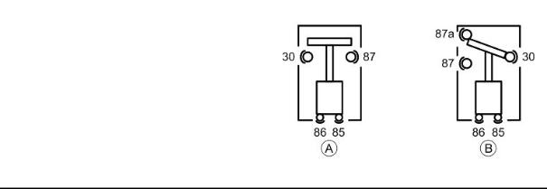
There are two types of remote controls in the electrical system, those operating as "circuit breakers" «A», and those operating as a "switches" «B».
CHAR - 6
GP 800 i.e. |
Characteristics |
|
|
CHECKING REMOTE CONTROLS «A» OPER-
ATING AS CIRCUIT BREAKERS
1)Check that, given regular conditions, there is no continuity between terminals 30 and 87.
2)Apply 12V voltage to power terminals 85 and 86 of the remote control.
3)With the remote control powered, check that there is continuity between terminals 30 and 87.
4)If these conditions are not fulfilled, the remote control is damaged and must be replaced.
CHECKING REMOTE CONTROLS «B» OPER-
ATING AS SWITCHES
1)Check that, given regular conditions, there is no continuity between terminals 30 and 87 but that there is continuity between terminals 30 and 87a.
2)Apply 12V voltage to power terminals 85 and 86 of the remote control.
3)With the remote control powered, check that there is continuity between terminals 30 and 87. However, there must be no continuity between terminals 30 and 87a.
4)If these conditions are not fulfilled, the remote control is damaged and must be replaced.
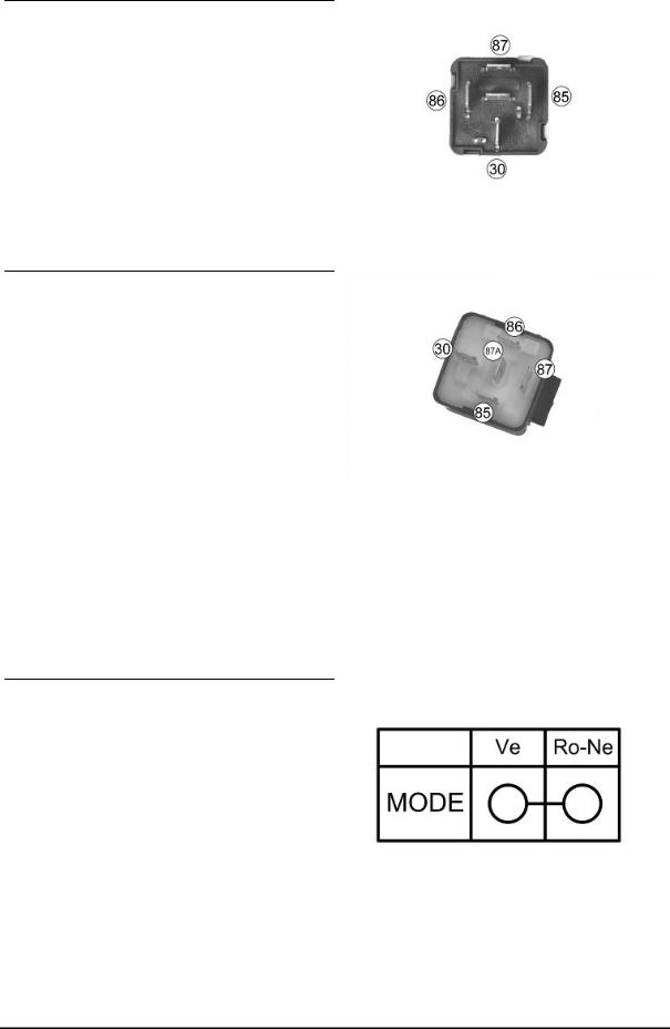
To check buttons and switches make sure that, according to their position, the continuity of contacts is correct, as indicated in the following tables.
«MODE» BUTTON
CHAR - 7
Characteristics
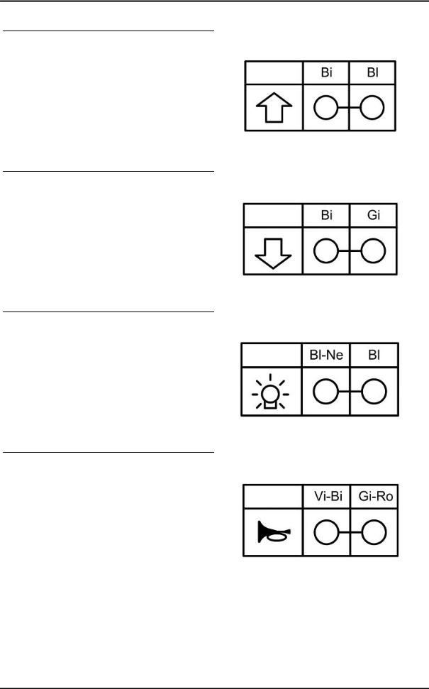
WINDSHIELD «UP» BUTTON
WINDSHIELD «DOWN» BUTTON
HELMET COMPARTMENT LIGHT BUTTON
HORN BUTTON
GP 800 i.e.
CHAR - 8
GP 800 i.e. |
Characteristics |
|
|
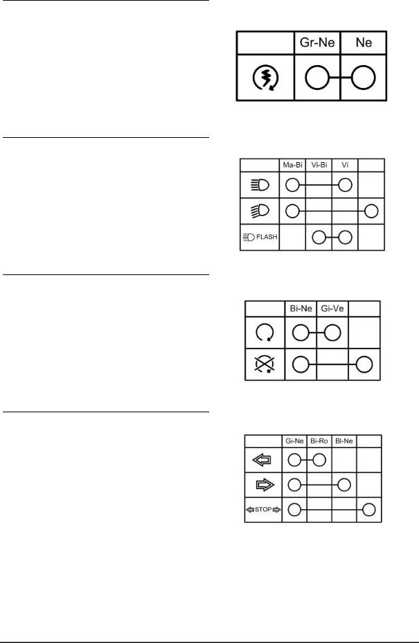
STARTER BUTTON
LIGHT SWITCH
ENGINE STOP SWITCH
TURN INDICATOR SWITCH
CHAR - 9
Characteristics
INTAKE AIR TEMPERATURE SENSOR
-10° = 9600 Ohm
0° = 5900 Ohm
+10° = 3800 Ohm
+20° = 2500 Ohm
-30° = 1700 Ohm
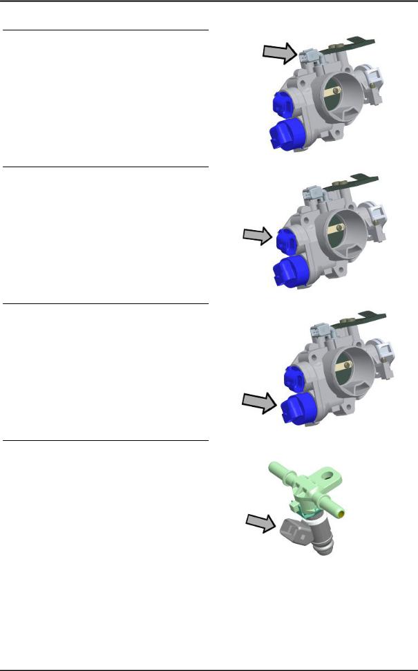
THROTTLE POSITION SENSOR
With the switch set to "ON" at a variable voltage between 0.7V and > 4V between pins 23 - 3 on engine-side wiring.
Ground insulation of pins 29 - 32 - 3 on engine-side wiring
STEPPER MOTOR
Resistance engine-side connector between pins 19 - 9 ~ 51 Ohm
Resistance engine-side connector between pins 18 - 17 ~ 51 Ohm
FUEL INJECTOR
Type: 4 holes
Conicity of the nozzle: 24°
Resistance at terminals: 13.7 ÷ 15.2 Ohm
GP 800 i.e.
CHAR - 10
GP 800 i.e. |
Characteristics |
|
|
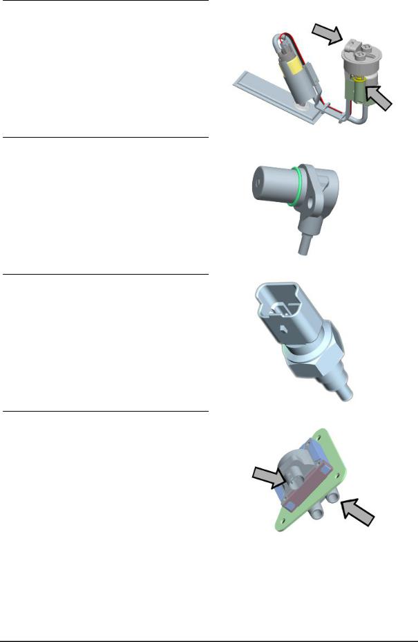
FUEL PUMP UNIT
Mechanical type pressure regulator operating at a pressure of 3 BAR
Pump winding resistance: ~ 1,5 Ohm
REVOLUTION TIMING SENSOR
Resistance between "+ and -" = 890 ± Ohm (pins 35 - 25 , engine-side wiring)
Insulation between "+ and S" and between "- and S" (pins 35 - 34 and 25 - 34, engine-side wiring)
ENGINE TEMPERATURE SENSOR
0° = 5900 Ohm
+10° = 3800 Ohm
+20° = 2500 Ohm
+30° = 1700 Ohm
+80° = 300 Ohm
H.V. COIL
Primary winding resistance: 520 ÷ 620 mOhm
Secondary resistance: 6830 ÷ 7830 Ohm
CHAR - 11
Characteristics |
GP 800 i.e. |
|
|
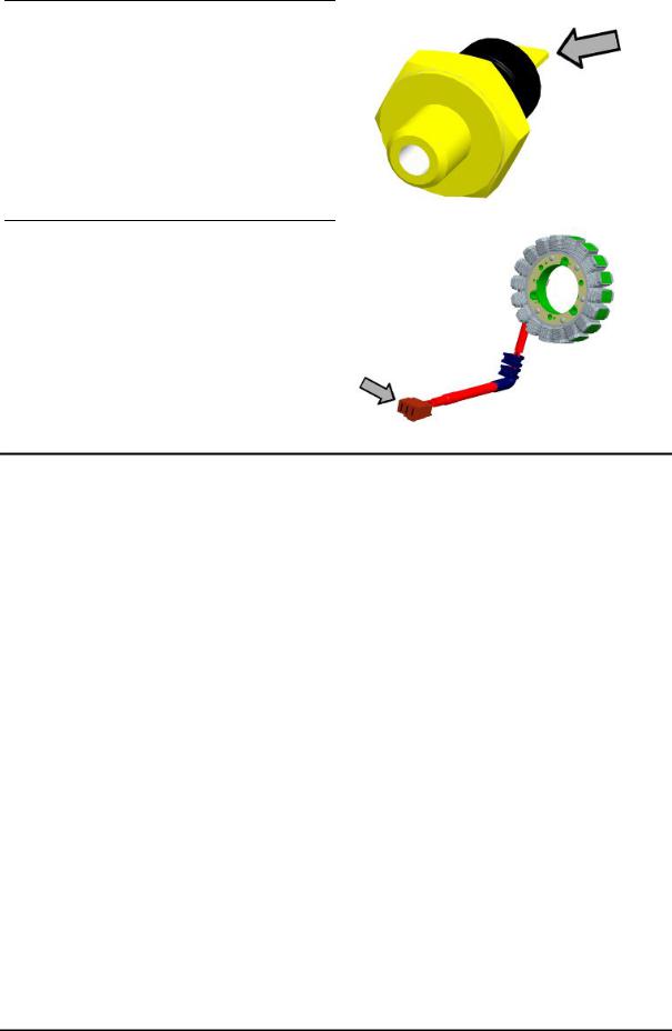
MINIMUM OIL PRESSURE SENSOR
Normally closed switch Activation threshold: 0.3 - 0.6 bar
With the engine off: continuity between terminal and ground
STATOR
Resistance between terminals: 0.2 ÷ 1 Ohm
Terminal insulation from ground
Frame and suspensions
FRAME AND SUSPENSIONS
|
Specification |
Desc./Quantity |
|
|
Chassis |
Double cradle with tubular and steel stamped |
|
|
|
plates |
|
|
Front suspension |
Hydraulic telescopic fork, single plate, ø 41-mm |
|
|
|
straight stems. |
|
|
Front suspension travel |
126 mm |
|
|
Oil quantity for stem |
295 ± 3 cm³ |
|
|
Unloaded spring length |
----- mm |
|
|
Rear suspension |
Single shock absorber that acts directly on the |
|
|
|
fork. |
|
|
Rear suspension travel |
135 mm |
|
|
|
|
|
Brakes |
|
|
|
|
|
BRAKES |
|
|
Specification |
Desc./Quantity |
|
|
Front brake |
Ø 300-mm double disc brake with hydraulic control |
|
|
|
activated by the handlebar right-hand lever. |
|
|
|
Two floating callipers, ø 28 double plunger |
|
|
Rear brake |
Ø 280-mm disc brake, with hydraulic servo oper- |
|
|
|
ated from the handlebar with the left-hand lever. |
|
|
|
One floating calliper with a single plunger |
|
|
|
|
|
CHAR - 12

GP 800 i.e. |
Characteristics |
|
|
Wheels and tyres
|
WHEELS AND TYRES |
|
|
|
|
|
Specification |
Desc./Quantity |
|
||
|
Wheel rim type |
Light alloy rims. |
|
||
|
Front rim |
16'' x 3.50 |
|
||
|
Rear rim |
15'' x 4.50 |
|
||
|
Front tyre |
Tubeless, 120/70 - 16" 57H |
|
||
|
Rear tyre |
Tubeless, 160/60 - 15" 67H |
|
||
|
Front tyre pressure (with passenger) |
2.5 bar (-) |
|
||
|
Rear tyre pressure (with passenger) |
2.75 bar (-) |
|
||
|
|
|
|
|
|
Tightening Torques |
|
|
|
|
|
|
LUBRICATION |
|
|
|
|
|
Name |
Torque in Nm |
|
||
|
Engine oil drainage plug |
21 |
÷ |
29 |
|
|
Bulkhead screws for oil pump housing cover |
3 |
÷ |
4 |
|
|
Engine oil filter |
12 - 16 |
|
||
|
Oil pump chain tensioner pad |
2 |
÷ |
3 |
|
|
Oil pump screws |
5 - 6 |
|
||
|
By-pass scavenge duct fixing screws |
11 |
÷ |
13 |
|
|
Lubrication circuit upper bulkhead |
3 |
÷ |
4 |
|
|
Oil pump crown screw |
10 |
÷ |
14 |
|
|
Screws fixing oil pump to the crankcase |
5 - 6 |
|
||
|
Minimum oil pressure sensor |
10 |
|
|
|
|
Water pump gear fixing screw |
5 - 6 |
|
||
|
THERMAL GROUP AND TIMING SYSTEM |
|
|
|
|
|
Name |
Torque in Nm |
|
||
|
Spark plug |
12 |
÷ |
14 |
|
|
Head fixing stud bolts: |
*** |
|
||
|
Head fixing nuts |
10 - 12 |
|
||
|
Exhaust / intake head fixing nuts: |
10 - 12 |
|
||
|
Head lubrication control jet |
5 - 7 |
|
||
|
Tensioner sliding block fixing screw: |
10 - 14 |
|
||
|
injector fixing screw |
3 |
÷ |
4 |
|
|
inlet manifold fixing screws |
11 - 13 |
|
||
|
Tappet cover fixing screws: |
7 - 9 |
|
||
|
Throttle body fixing screws |
11 |
÷ |
13 |
|
|
camshaft retaining bracket fixing screws |
4 - 6 |
|
||
|
Head fixing screws |
10 - 12 |
|
||
|
Coolant temperature sensor |
21 |
÷ |
23 |
|
|
Revolution timing sensor fixing screw |
7.5 |
÷ |
8.5 |
|
|
Timing system chain tensioner screw |
11 |
÷ |
13 |
|
|
Timing system gear on camshaft screw |
12 |
÷ |
14 |
|
*** Apply a preliminary torque of 10 Nm in a criss-crossed sequence. - tighten with a torque of 13 Nm + 90° in a criss-crossed sequence. - tighten again by 90° in a criss-crossed sequence.
|
TRANSMISSION COVER |
Name |
Torque in Nm |
Drive pulley nut |
252 ÷ 278 |
CHAR - 13

Characteristics |
GP 800 i.e. |
|
|
Name |
Torque in Nm |
|
Driven pulley nut |
153 |
÷ 187 |
Clutch ring nut |
65 - 75 |
|
External transmission cover screws |
5 |
÷ 7 |
Internal transmission cover screws |
11 |
÷ 13 |
Air switch screw |
3 |
÷ 4 |
Air outlet grille screws |
3 |
÷ 4 |
FLYWHEEL COVER
Name |
Torque in Nm |
|
Flywheel fixing nut |
116 |
÷ 128 |
Stator retainers |
8 - 10 |
|
Screw fixing freewheel to flywheel |
13 |
÷ 15 |
Flywheel cover screws |
11 - 13 |
|
CRANKCASE AND CRANKSHAFT
Name |
Torque in Nm |
|
Starting ring gear retaining plate |
3 |
÷ 4 |
Engine crankcase coupling screws (M6) |
11 |
÷ 13 |
Engine crankcase coupling screws (M8) |
25 |
÷ 28 |
COOLING |
|
|
Name |
Torque in Nm |
|
Water pump rotor cover |
3 |
÷ 4 |
bleed screw |
3 |
÷ 4 |
Water pump impeller |
4 |
÷ 5 |
Screws tightening water pump gear protection |
3 |
÷ 4 |
plate |
|
|
CHASSIS |
|
|
Name |
Torque in Nm |
|
Side stand bolt nut |
|
37 |
Screws fixing side stand button |
|
6 |
Screw fixing electric fan - radiator |
2 |
÷ 3 |
Screw fixing radiator - chassis |
5 |
÷ 7 |
Nut fixing silent-block plate - chassis |
22 |
÷ 25 |
Nut fixing silent-block plate |
33 |
÷ 41 |
Pin fixing nut - M14 |
124 |
÷ 153 |
Pin fixing nut - M10 |
47 |
÷ 52 |
Upper nut fixing engine support link rods - chassis |
33 |
÷ 41 |
Lower nut fixing engine support link rods - chassis |
33 |
÷ 41 |
Nut fixing head - exhaust manifold |
16 |
÷ 18 |
Centre stand front bolt nut |
34 |
÷ 39 |
Centre stand rear bolt nut |
74 |
÷ 81 |
Screw fixing silencer - muffler support arm |
|
11 |
Screw fixing catalytic converter - catalytic convert- |
22 |
÷ 24 |
er support |
|
|
Screw fixing muffler support arm - engine |
24 |
÷ 27 |
Silencer fixing screw |
|
22 |
Manifold retainer clamp |
16 |
÷ 18 |
CHAR - 14
GP 800 i.e. |
Characteristics |
|
|
PINION UNIT |
|
|
Name |
Torque in Nm |
|
Screw for plate locking pinion driving bushing |
4 ÷ 6* |
|
Screws fixing pinion unit cover |
4 ÷ 5* |
|
Screws fixing pinion unit - chassis |
|
50 |
Pinion unit oil drain screw |
13 |
÷ 15 |
Pinion unit oil filling screw |
13 |
÷ 15 |
Oil sealing casing clamp |
3 |
÷ 5 |
(*) Apply LOCTITE 243 threadlock |
|
|
HANDLEBAR |
|
|
Name |
Torque in Nm |
|
Screws fixing handlebar supporting plate - steer- |
50 |
÷ 55 |
ing tube |
|
|
Screws fixing frame - supporting plate |
4.5 ÷ 7 |
|
Screws fixing half-handlebars - supporting plate |
20 ÷ 25* |
|
Screw fixing half-handlebar insert - half-handlebar |
20 ÷ 25* |
|
Handlebar cover fixing screw |
2.5 ÷ 4 |
|
Brake pump stand fixing screws |
7 ÷ 10 |
|
(*) Apply LOCTITE 243 threadlock |
|
|
MISCELLANEOUS |
|
|
Name |
Torque in Nm |
|
starter motor retainers |
11 - 13 |
|
BRAKE SYSTEM |
|
|
Name |
Torque in Nm |
|
Brake pipes / rear brake calliper coupling |
20 |
÷ 25 |
Brake pipes / brake pump coupling |
16 |
÷ 20 |
Screws fixing front brake disc to rim |
|
25 |
Screws fixing rear brake disc to rim |
|
25 |
Screws fixing brake pump to handlebar |
7 ÷ 10 |
|
Screw fixing three-way union to fork head |
10 |
÷ 12 |
Screws fixing front brake calliper to fork |
20 |
÷ 25 |
Screw fixing rear brake calliper to supporting plate |
20 |
÷ 25 |
Screw fixing parking brake calliper to supporting |
24 |
÷ 27 |
plate |
|
|
Brake calliper bleed screw |
4 |
÷ 7 |
Parking brake adjusting nut |
|
10 |
Nut fixing rear brake pipe retaining clip |
11 |
÷ 13 |
Pin fixing parking brake pads |
15 |
÷ 20 |
Brake pipes / three-way union coupling |
18 |
÷ 23 |
Brake pipes / front brake calliper coupling |
16 |
÷ 20 |
Rear brake pad fixing pins |
15 |
÷ 20 |
FRONT SUSPENSION |
|
|
Name |
Torque in Nm |
|
Screw fixing wheel pin on right fork leg |
6 |
÷ 7 |
Front wheel pin nut |
60 |
÷ 70 |
Hydraulic rod fixing screw |
25 ÷ 35* |
|
Fork locking screws cap |
35 - 55 |
|
Stem support clamp tightening screws |
20 |
÷ 25 |
CHAR - 15
Characteristics |
GP 800 i.e. |
|
|
Name |
Torque in Nm |
Steering tube lower ring nut |
20 ÷ 22 |
Steering tube upper ring nut |
48 ÷ 54 |
(*) Apply LOCTITE 243 threadlock |
|
REAR SUSPENSION
Name |
Torque in Nm |
Nut fixing shock absorber - fork |
38 - 46 |
Screw fixing shock absorber - fork |
38 - 46 |
Screw fixing chain stop slider - fork |
5 ÷ 7 |
Screw fixing centre stand stop buffer - fork |
5 ÷ 7 |
Crown fixing screws |
22.5 ÷ 27.5* |
Rear wheel pin nut |
70 |
Fork locking ring nut |
60 ± 3 Nm |
Fork pin set screw |
0.5 |
Fork pin nut |
90 ± 5 |
(*) Apply LOCTITE 243 threadlock
Overhaul data
Assembly clearances
Cylinder - piston assy.
CHAR - 16
GP 800 i.e. |
Characteristics |
|
|
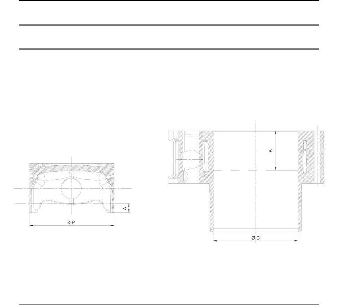
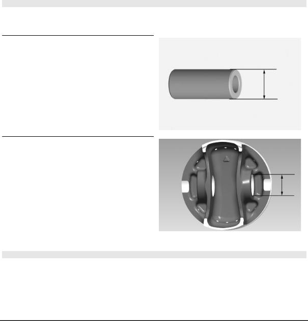
HEIGHT TO MEASURE THE PISTON
Specification |
Desc./Quantity |
A |
10 mm |
B |
43 mm |
|
CYLINDER - PISTON |
Specification |
Desc./Quantity |
Cylinder diameter C |
88 +0.018-0.01 mm |
Piston Ø P |
87.968 ±0.014 mm |
COUPLING CATEGORIES
Name |
Initials |
Cylinder |
Piston |
Play on fitting |
CylinderPiston |
A |
87.990÷87.997 |
87.954÷87.961 |
0.029÷0.043 |
CylinderPiston |
B |
87.997 ÷ 87.004 |
87.961 ÷ 87.968 |
0.029÷0.043 |
CylinderPiston |
C |
88.004÷88.011 |
87.968÷87.975 |
0.029÷0.043 |
CylinderPiston |
D |
88.011÷88.018 |
87.975 ÷ 87.982 |
0.029÷0.043 |
N.B.
THE PISTON MUST BE INSTALLED WITH THE ARROW FACING TOWARDS THE EXHAUST SIDE, THE PISTON RINGS MUST BE INSTALLED WITH THE WORD «TOP» OR THE STAMPED MARK FACING UPWARDS.
- Calculate the coupling clearance between pin and connecting rod end.
Characteristic
Standard clearance:
0.015 ÷ 0.029 mm
- Measure the capacity diameter on the piston.
Characteristic
Standard diameter:
22 + 0.006 + 0.001 mm
- Calculate the piston pin coupling clearance.
N.B.
THE PIN HOUSINGS HAVE 2 LUBRICATION CHANNELS. FOR THIS REASON, MEASUREMENT MUST BE MADE ACCORDING TO THE PISTON AXIS.
Characteristic
Standard clearance:
0.001 ÷ 0.010 mm
CHAR - 17

Characteristics |
GP 800 i.e. |
|
|
-Check that coating is free from flakes.
-Check that the head matching surface exhibits no deformations or wear.
Characteristic
Maximum allowable run-out:
0.05mm
-Pistons and cylinders are classified into categories based on their diameter. The coupling is carried out in pairs (A-A, B-B, C-C, D-D).
Piston rings
*Fit rings «2» and «3» with the word «TOP» facing upwards. ** Position the openings in the rings as shown here.
***Value «A» of sealing ring inside the cylinder.
Check the size of the sealing ring opening:
Compression ring: 0.15 ÷ 0.35 mm. Max. value 0.5 mm
Oil scraper ring: 0.25 ÷ 0.50 mm. Max. value 0.65 mm
Oil scraper ring: 0.25 ÷ 0.50 mm. Max. value 0.65 mm
CHAR - 18
GP 800 i.e. |
Characteristics |
|
|
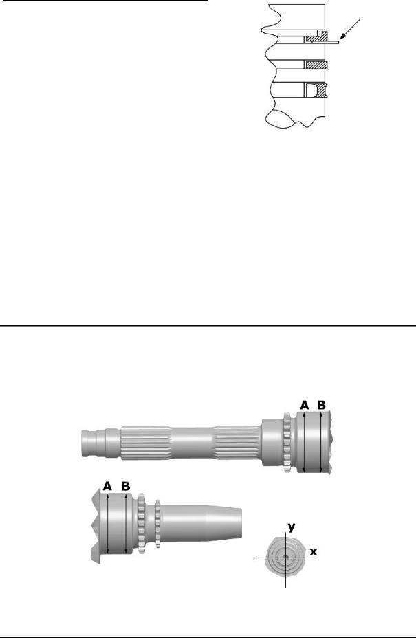
Rings/housing coupling clearances:
Carefully clean the sealing ring housings.
Place a thickness gauge between the ring and the housing as shown in the drawing and check the coupling clearances.
Top ring Standard coupling clearance:
0.01÷0.06 mm
Maximum clearances allowed after use: 0.10 mm
Intermediate ring Standard coupling clearance:0.02÷0.07 mm
Maximum clearances allowed after use: 0.10 mm
Oil scraper ring Standard coupling clearance:
0.01÷0.06 mm
Maximum clearances allowed after use: 0.10 mm
Replace the piston if clearances exceed the maximum limits specified in the table.
Crankcase - crankshaft - connecting rod
Diameter of crankshaft bearings.
Measure the capacity on both axes x-y.
CHAR - 19
Characteristics |
GP 800 i.e. |
|
|
|
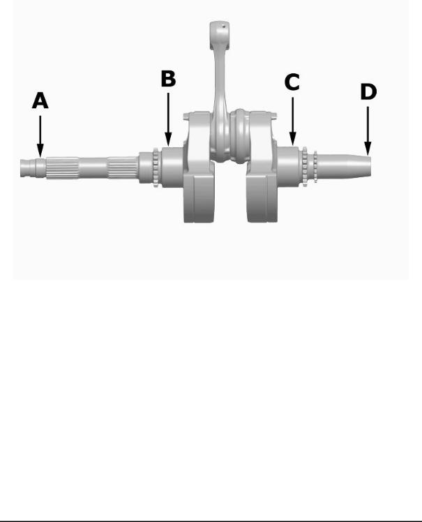
CRANKSHAFT |
Specification |
Desc./Quantity |
Cat. 1 |
Standard diameter: 45.010 ÷ 45.016 |
Cat. 2 |
Standard diameter: 45.016 ÷ 45.022 |
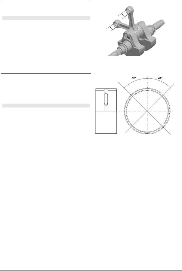
Crankshaft alignment |
|
Specific tooling
020335Y Magnetic support for dial gauge
MAX. ADMISSIBLE DISPLACEMENT
Specification |
Desc./Quantity |
A = |
0.15 mm |
B = |
0.010 mm |
C = |
0.010 mm |
D = |
0.10 mm |
CHAR - 20
GP 800 i.e. |
Characteristics |
|
|
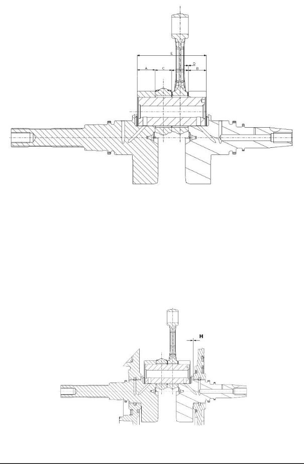
AXIAL CLEARANCE BETWEEN CRANKSHAFT AND CONNECTING ROD
Name |
Description |
Dimensions |
Initials |
Quantity |
Half-shaft, trans- |
|
23.8 +0.1 |
A |
D = 0.20 ÷ 0.55 |
mission side |
|
|
|
|
Flywheel-side half- |
|
23.8 + 0.1 |
B |
D = 0.20 ÷ 0.55 |
shaft |
|
|
|
|
Connecting rod |
|
22 -0.10 - 0.15 |
C |
D = 0.20 ÷ 0.55 |
Complete crank- |
|
91.8 +0.05 |
E |
D = 0.20 ÷ 0.55 |
shaft |
|
|
|
|
Characteristic
Crankshaft-crankcase axial clearance (H)
CHAR - 21
Characteristics |
GP 800 i.e. |
|
|
0.1 ÷ 0.45 mm (when cold)
- Using a bore gauge, measure the connecting rod small end diameter.
N.B.
IF THE CONNECTING ROD SMALL END DIAM-
ETER EXCEEDS THE STANDARD DIAMETER,
EXHIBITS WEAR OR OVERHEATING, PRO-
CEED TO REPLACE THE CRANKSHAFT AS
DESCRIBED IN CHAPTER CRANKCASE AND
CRANKSHAFT.
Characteristic
Standard diameter:
22 + 0.025 +0.015 mm
-Check the inside diameter of the main bushings in the three directions indicated in the diagram.
-Repeat the measurements for the other bushing half. see diagram.
N.B.
DO NOT TAKE THE MEASUREMENT ON THE
TWO HALF-SHELL COUPLING SURFACE
SINCE THE ENDS ARE RELIEVED TO ALLOW
BENDING DURING THE DRIVING OPERATION.
Before assembling, check that the clearance between the engine crankcase bushing and the crankshaft is within the predetermined limits.
Characteristic
Crankshaft-bushing maximum clearance admitted:
0.08 mm
-The standard bushing diameter after driving is variable on the basis of a coupling selection.
-The bushing seats in the crankcase and the crankshaft are classified into 2 categories.
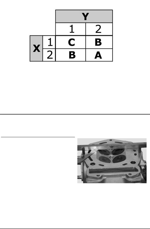
-Bushings are subdivided into 3 categories according to their thickness (see the table).
The following kinds of bushings indicated in the table must be used according to the kind of coupling between the crankshaft and the crankcase.
CHAR - 22
GP 800 i.e. |
Characteristics |
|
|
KEY
X = Crankshaft category
Y = Crankcase half-shell category
A = Red
B = Blue
C = Yellow
Cylinder Head
Before performing head service operations, thoroughly clean all coupling surfaces. Note the position of the springs and the valves so as not to change the original position during refitting
- Using a trued bar and feeler gauge check that the cylinder head surface is not worn or distorted.
Characteristic
Maximum allowable run-out:
0.1mm
-In case of irregularities, replace the head.
-Check the sealing surfaces for the intake and exhaust manifold.
-Check that the camshaft and the rocker pin capacities exhibit no wear.
-Check that the head cover surface is not worn.
-Check that the coolant sealing pad exhibits no oxidation.
CHAR - 23
Characteristics |
GP 800 i.e. |
|
|
-Insert the valves into the cylinder head.
-Alternatively check the intake and exhaust valves.
-The test is carried out by filling the manifold with petrol and checking that the head does not ooze through the valves when these are just pressed with the fingers.
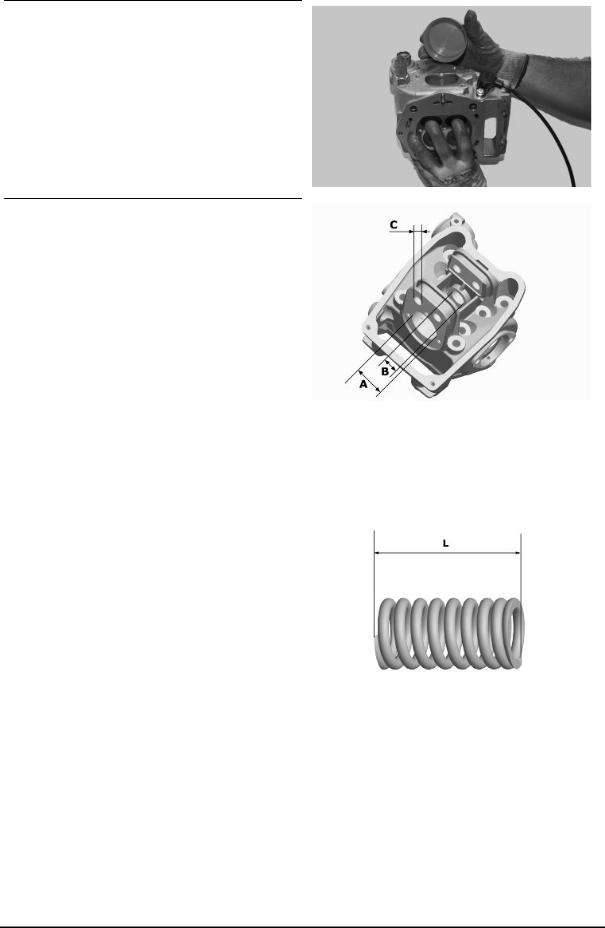
Measure the camshaft bearing seats and rocking lever support pins with a bore meter
|
HEAD BEARINGS |
Specification |
Desc./Quantity |
Bearing "A" |
42 +0.025 |
Bearing "B" |
19.5 -0.2 |
Bearing "C" |
13 +0.018 |
|
|
- Measure the unloaded spring length. |
|
Characteristic
Standard length:
44.4 mm
Admissible limit after use:
42.4 mm
CHAR - 24
 Loading...