

WORKSHOP MANUAL
COGUAR

Reproduced by
OWNERS CLUB
OF BRITAIN
from information obtained from original or copied
manuals originally issued by
Piaggio/Gilera
Whilst every care has been taken to ensure
accuracy of the contents, I Gotta Gilera does not
accept any liability of any type due to any errors or
omissions, and use of this manual will denote
acceptance of this condition.
NOTES:
We have found one obvious error within the original manual, but have copied it
exactly as it originally appeared together with a note advising that it is an error.
If you find any other errors, please email pppdrive@talktalk.net so that this manual
can be updated to be as accurate as is possible.
COGUAR WORKSHOP MANUAL
This manual was written by Piaggio-Gilera for use in Piaggio-Gilera
dealers and authorised servicing workshops. It is assumed that the
person using this manual for maintenance and repairs on Piaggio-Gilera
Coguar models has a basic knowledge of mechanical principles and
procedures concerning vehicle repair techniques.
Information concerning important variations in vehicle characteristics or in
certain repair operations will be communicated as an update to this
manual.
However, it is not possible to carry out a completely satisfactory job
without the necessary systems and tools. Therefore, please consult the
pages in this manual dealing with special tools and the special equipment
catalogue.
NOTE This indicates a note that gives important information to make the
………..procedure clearer and easier to carry out.
Important note
Warning
This indicates certain precautions that are to be taken to avoid
injuries to the person repairing the vehicle.
NOTE - For all that concerns the specific operations on the Coguar
………….engine, see the “SERVICE STATION MANUAL 4T SPEED
………….125cc ENGINE.”
This indicates special procedures that are to be followed
to avoid damaging the vehicle.
GENERAL INFORMATION
Safety regulations
If it is necessary to work on the vehicle with the engine running, make sure that the
environment is well ventilated, if necessary using a suitable exhaust system. Never
run the engine in closed places since the exhaust gasses are toxic.
The battery electrolyte contains sulphuric acid. Protect your eyes, clothes and skin.
Sulphuric acid is highly corrosive; if it comes into contact with the eyes or skin, wash
with plenty of water and go immediately to a Doctor.
The battery produces hydrogen which can be highly explosive. Do not smoke and
avoid naked flames and sparks near the battery, especially when recharging it.
Petrol is very inflammable and under some conditions can explode. Do not smoke
in the work area and keep clear of naked flames and sparks.
Clean the brake shoes, drums and pads in well ventilated areas directing the
compressed air jet to avoid taking in the dust caused by the wear on the shoes.
Although the brake lining does not contain asbestos, inhalation of the dust is still
harmful.
Maintenance rules
Use original PIAGGIO-GILERA spare parts and lubricants recommended by the
manufacturer. Spare parts other than originals or that do not conform can damage
the vehicle.
Only use the special tools designed for this vehicle.
Always use new seals, seal rings and split pins when assembling.
After disassembly, clean the components with non flammable solvent. Lubricate all
working surfaces before reassembling, except for the bevel pairs.
After reassembly, check that all the components have been installed correctly and
operate perfectly.
For disassembly, overhaul and reassembly operations, only use tools with metric
measurements. The metric screws, nuts and bolts are not interchangeable with
English measurement couplings. The use of unsuitable tools or couplings could
damage the vehicle.
When working on the vehicle electrical system, check the correct assembly of the
electrical connections, especially those connecting the to earth and the battery.
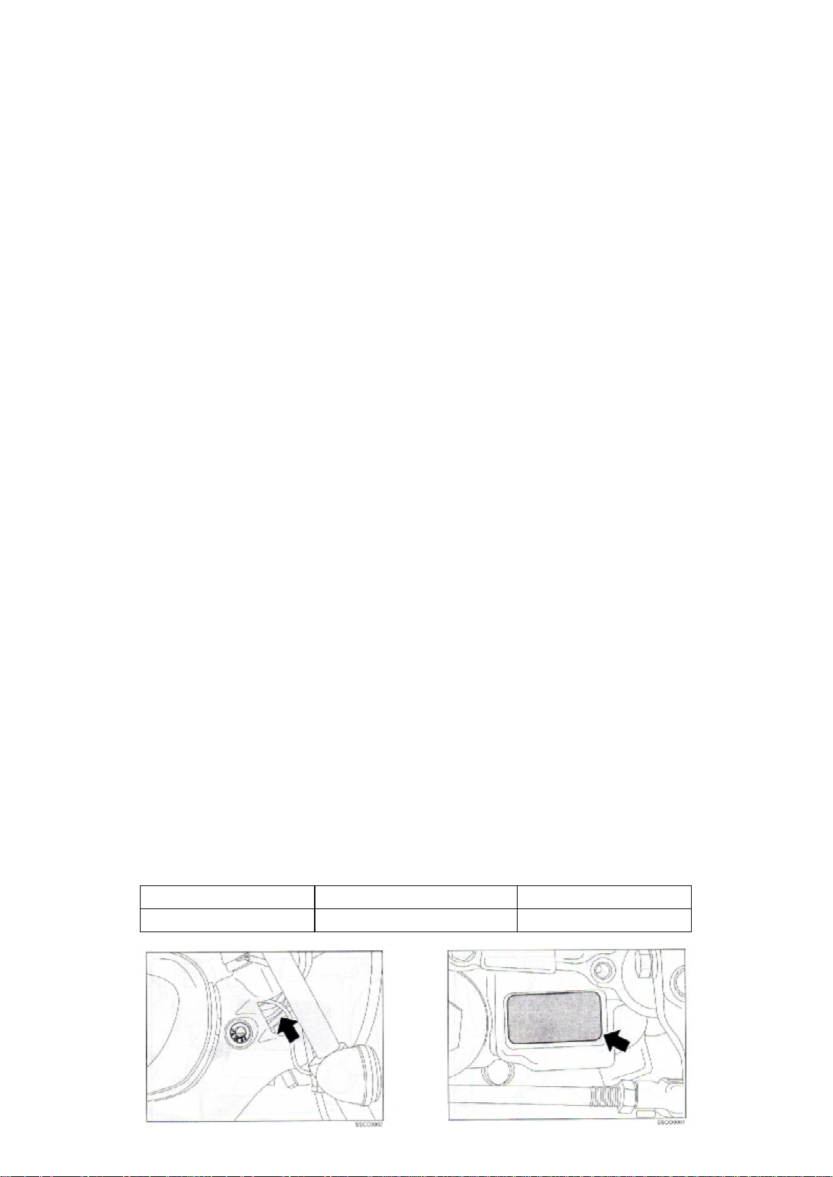
Vehicle identification
Vehicle
COGUAR 125 cc
Frame prefix
ZAPM1700000001001
Engine prefix
JD09E

INDEX
Specifications
Vehicle overhaul data
Special equipment
Maintenance and troubleshooting
Electrical system
Front suspension
Rear suspension
Braking system
Pre-delivery operations
Section
1
1
1
2
3
4
5
6
7

GENERAL INFORMATION 1
SUB INDEX
Specifications
Torque settings
Section - Page
1 - 1
1 - 2
1
SPECIFICATIONS
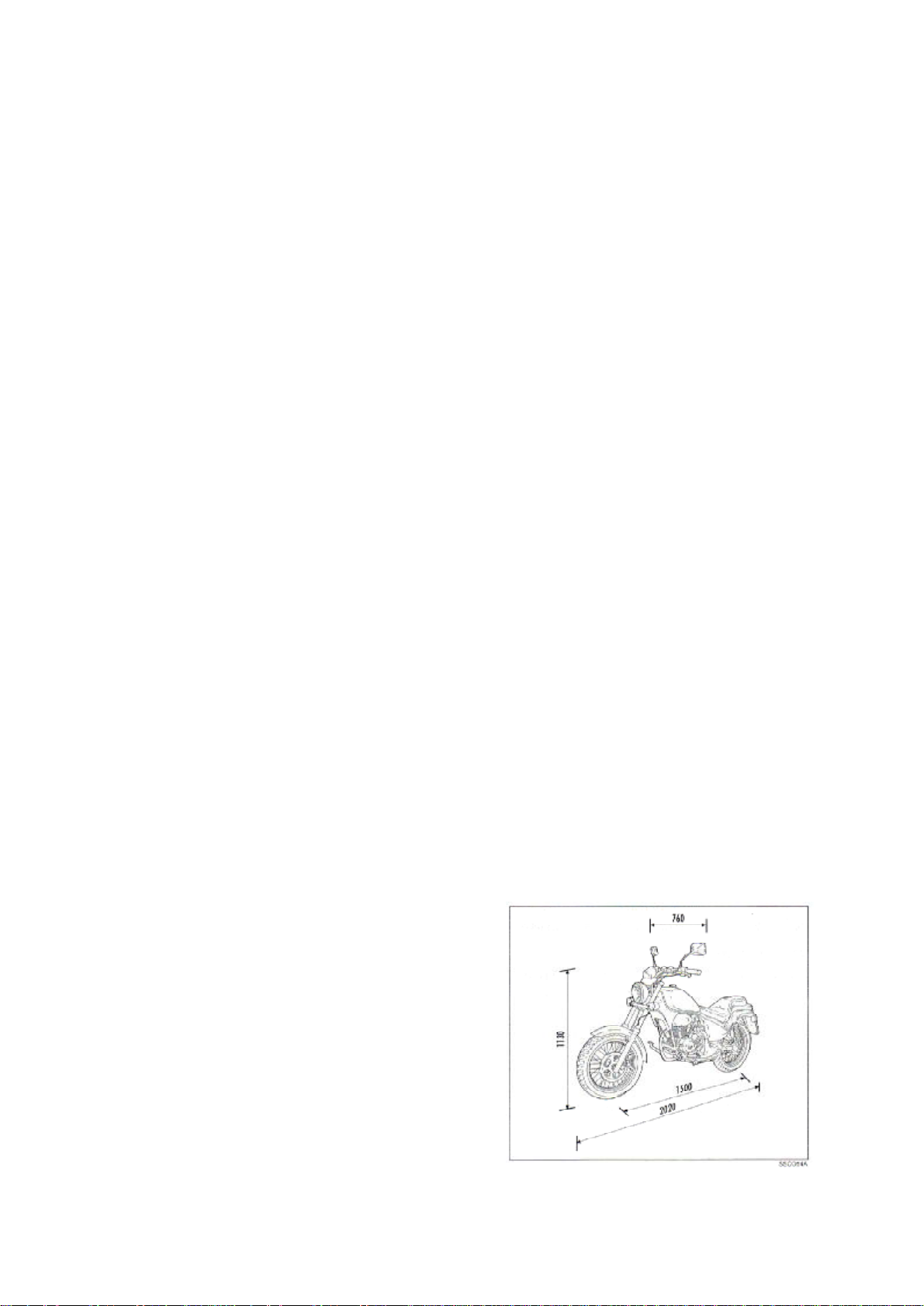
Dimensions and weight
Width
Length
Wheelbase
Height
Dry weight
760mm
2020mm
1500mm
1130mm
141kg
Engine
Type
4 stroke
Cylinders
Bore
Stroke
Capacity
Comp. Ratio
56.5mm
49.5mm
124cc
9.2±0.5:1
Timing: single shaft with cams
in head, two valves, chain
driven on right-hand side.
Carburettor
Air Cleaner
Start up
Lubrication
Fuel supply
Cooling
KEIHIN PDC3F
Paper
Electric starter
Forced, wet sump
Unleaded petrol,
carburettor,
gravity system
Air
Performance
Engine idling
Max power at
shaft
Max torque at
shaft
Max speed
1400±100rpm
7.9kW/8250rpm
10Nm/7000rpm
102kph
Transmission
Geared primary, chain secondary.
Capacities
Petrol (inc reserve) 12 lt
Reserve 2.2 lt
Engine oil
Sump 1.0 lt
Total system capacity 1.2 lt
Fork oil 280cc
Frame
1
Single tube with double closed cradle.
Suspension
Front: Hydraulic fork with 35mm rod
………..and 130mm stroke.
Rear: Dual shock-absorbing element
………...with 84mm stroke.
Brakes
Front: 260mm diameter disc, with
…………hydraulic control dual floating
…………shoe, lever on r-h handlebar.
Rear: 160mm diameter drum, with
…………mechanically controlled
…………expansion calliper.
Wheels
Stainless steel spokes aluminium rims
Front: 2.50 X 17”
Rear: .3.00 X 17”
Tyres
Front: .100/80 - 17”
Rear: 130/70 - 17”
Pressures (cold):
Front: 1.8 bar (1.9 with passenger)
Rear: 2.0 bar (2.2 with passenger)
Electrical components
Generator
Ignition
3 phase, ac
Electronic with
variable spark
Spark advance
(before TDC)
Spark plug
Battery
15° at 1400rpm
32° at 3450rpm
NGK DPR8EA-9
ND X204EPR-U9
12V - 9Ah
advance
1-1

TORQUE SETTINGS
FASTENING
Engine to frame (rear)
Engine (front & upper)
Side stand to frame
Stand fastening nut
Pedal plate to frame
Chain guard
Handlebar to upper plate
Fork upper plate to rods
Fork lower plate to rods
Fork lower ring
Fork upper ring
Front brake shoe to fork
Shoe/pump fitting
Front wheel axle
Front wheel fastening bolt
Rear shock absorber to frame
Fork to frame
Rear wheel axle
Block retainer
Front brake pump fastening U-bolt
L-H lever holder fastening U-bolt
Throttle grip
Light/indicators device
Saddle to frame
Tank to frame
Filter casing to frame front
Filter casing to frame rear
Tool box to frame
R-H & L-H tube cover
Headlight bracket to upper plate
Km cntr bracket to headlight plate
Headlight to bracket
Front mudguard to fork
Rear light to mudguard
Breather
Handles to frame front
Handles to frame rear
Spray guard to frame
Pinion guard
Exhaust pipe to frame
Exhaust pipe to engine
Gear lever
THREAD
Screw M10x1.25
Screw M8
Screw M10x1.25
Nut M10x1.25
Screw M10
Screw M6
Nut M10
Screw M8
Screw M10x1.25
M25x1
M24x1
Screw M8
Screw M10
M 12x1.25
Screw M8
Screw M12
Screw M12x1.25
Screw M14x1.5
Screw M10x1.25
Screw M6
Screw M6
Screw M5
Screw M5
Screw M6
Screw M6
Screw M6
Screw M6
Screw M6
Screw M5
Screw M5
Screw M5
Screw M5
Screw M6
Nut M6
Screw M6
Screw M6
Screw M8
Screw M6
Screw M6
Screw M10x1.25
Nut M6
Screw M6
TORQUE in
Nm (kgm)
32÷40 (3.2÷4.0)
20÷25 (2.0÷2.5)
40÷45 (4.0÷4.5)
40÷45 (4.0÷4.5)
20÷22 (2.0÷2.2)
4÷7 (0.4÷0.7)
45÷50 (4.0÷5.0)
20÷22 (2.0÷2.2)
35÷40 (3.5÷4.0)
27÷33 (2.7÷3.3)
37÷43 (3.7÷4.3)
20÷22 (2.0÷2.2)
13÷17 (1.3÷1.7)
65÷70 (6.5÷7.0)
20÷22 (2.0÷2.2)
70÷80 (7.0÷8.0)
65÷70 (6.5÷7.0)
60÷70 (6.0÷7.0)
40÷45 (4.0÷4.5)
6÷7 (0.6÷0.7)
6÷7 (0.6÷0.7)
3÷4 (0.3÷0.4)
3÷4 (0.3÷0.4)
4÷7 (0.4÷0.7)
4÷7 (0.4÷0.7)
4÷7 (0.4÷0.7)
4÷7 (0.4÷0.7)
4÷7 (0.4÷0.7)
4÷7 (0.4÷0.7)
5÷8 (0.5÷0.8)
5÷8 (0.5÷0.8)
5÷8 (0.5÷0.8)
8÷10 (0.8÷1.0)
4÷7 (0.4÷0.7)
4÷7 (0.4÷0.7)
7÷10 (0.7÷1.0)
20÷22 (2.0÷2.2)
8÷10 (0.8÷1.0)
4÷7 (0.4÷0.7)
40÷45 (4.0÷4.5)
10÷12 (1.0÷1.2)
4÷7 (0.4÷0.7)
1-2,1

Tightening torque Nm (kgm) according to type of material tightened
Steel screw
8.8 diam.
M4
M5
M6
M7
M8
M10
M12
M14
Plastic with
metal spacer
2 (0.2)
4 (0.4)
6.5 (0.65)
Brass, Copper,
aluminium and
alloys
2 (0.2)
4 (0.4)
6.5 (0.65)
10.5 (1.05)
16 (1.6)
Iron, steel
3 (0.3)
6 (0.6)
10.5 (1.05)
17 (1.7)
26 (2.6)
52 (5.2)
100 (10.0)
145 (14.5)
1-2,2

MAINTENANCE AND TROUBLESHOOTING 2
SUB INDEX
Schedule Servicing times
Troubleshooting
Section - Page
2 - 1
2 - 2
2

SCHEDULED SERVICE
CHECK
REPLACE
Km X 1,000
Months
Nuts, bolts & fastenings
Spark Plug
Drive Chain (clean & lubricate)
Engine oil vapour recovery circuit
Engine idling speed
Air Cleaner
Engine oil mesh filter (clean)
Centrifuge engine oil filter (clean)
Brake Shoes (adjust)
Valve clearance (adjust)
Electrical system & battery
Brake & Clutch Levers (grease)
Front Brake fluid level
1 6 12 18 24 30 36 42 48 54 60
4 12 24 36
Drain at each of scheduled times in header above
Check/adjust at each of sched times in header above
Every 500 kms
Brake Fluid
Engine Oil
Front Brake Pads
Tyre pressure & wear
Headlight (check & adjust)
Drive chain guard, check for wear
Vehicle & brake test (road test)
Km counter transmission (lube)
Suspension (check operation)
Steering (adjust)
Throttle transmission (adjust)
Clutch transmission (adjust)
Transmission (lubricate)
Front Brake Pipe
Coupon labour time
65 75
Replace Every 2 Years
Replace Every 3,000 kms
130
75
130
90
130
75
130
75
155
Engine oil
Cable lube oil
Km counter
Trans. Grease
Joint/pin grease
Brake fluid
Specifications
SAE 20W/50 synthetic oil exceeding API SG
Four-stroke engine oil
Lithium-based soap grease, NLG13
Complex calcium-based soap grease NLG12
SAE J1703, NHTSA 116 DOT4, ISO 4925
Recommended
Selenia HI Scooter 4T
Selenia HI Scooter 4T
JOTA 3 FS
Arexons system TW249
TUTELA TOP 4
2-1

SYMPTOM
Engine turns
but does not
start.
Irregular idling
ratio, poor
performance,
the engine
stops.
The engine
misfires when
accelerating.
Fuel delay on
accelerating.
Poor
performance
or high fuel
consumption
Backfire.
Lean mixture.
Rich mixture.
Idling speed
too high.
TROUBLESHOOTING
FUEL FEED
POSSIBLE CAUSE
No fuel in tank.
Engine flooded.
No spark (faulty ignition
system).
Air cleaner clogged up.
Intake air leakage.
Faulty throttle control.
Faulty starter.
Faulty ignition system.
Dirt in fuel
Irregular air intake.
Incorrect idling ratio.
Incorrect idling mixture
screw calibration.
Poor compression in
cylinder.
Starter jammed.
Rich mixture.
Lean mixture.
Carburettor clogged up
Faulty ignition system.
Lean mixture.
Faulty ignition system.
Lean mixture.
Fuel feed clogged up.
Faulty ignition system.
Air cleaner clogged up.
Faulty ignition system.
Faulty carburettor.
Lean mixture.
Rich mixture.
Fuel nozzles clogged up.
Faulty float valve.
Fuel tank breather
clogged up.
Fuel filter clogged up.
Fuel feed tube squeezed.
Breather clogged up.
Incorrect air intake.
Air cleaner clogged up.
Taper pin or taper nozzle
worn.
Faulty float valve.
Float level too high.
Starter jammed.
Irregular air intake.
REMEDY
Refuel.
Turn the starter to position 3 (off). Open the throttle
fully and turn engine for a few seconds. Do not
persist in turning starter motor.
Check the connections and the battery charge.
Possible problems may concern the coil, the control
unit or the impulse generator.
Replace the air cleaner.
Check the air cleaner and the carburettor.
Check the throttle control free travel. If required
adjust the cable tension.
Check the starter (and lubricate if required).
Check the battery, the ignition coil, the control unit,
the spark plug and all connections.
Drain and wash out the tank & the carburettor.
Check the air cleaner, the carburettor & the intake
manifold.
Adjust.
Adjust.
Check the head and spark plug fastening. Replace
the gas rings or the head gasket if, required.
Release and lubricate the starter.
Check the air cleaner condition.
Check the air cleaner condition.
Overhaul the carburettor.
Check the battery, the ignition coil, the control unit,
the spark plug and the respective connections.
Check the air cleaner condition.
Check the battery, the ignition coil, the control unit,
the spark plug and the respective connections.
Check the air cleaner condition.
Clean the tube.
Check the battery, the ignition coil, the control unit,
the spark plug and the respective connections.
Replace the air cleaner.
Check the battery, the ignition coil, the control unit,
the spark plug and the respective connections.
Check and replace if required.
Check the air cleaner condition.
Check the air cleaner condition.
Overhaul the carburettor.
Replace the complete float.
Clean the hole.
Replace the filter.
Clean the tube.
Clean the tube.
Check the cleaner, the carburettor and the intake
manifold.
Replace the air cleaner.
Replace.
Replace the complete float.
Adjust.
Release and lubricate the starter.
Check the air cleaner, the carburettor & the intake
manifold.
2-2,1

CLUTCH AND GEARBOX LINKAGES
SYMPTOM
Clutch lever
is too stiff.
Clutch does not
disengage or bike
moves slowly with
clutch disengaged.
Clutch slips.
The gears
are difficult
to engage.
The gears
slip
POSSIBLE CAUSE
The clutch cable is damaged, twisted
or dirty.
Incorrect clutch cable route.
Faulty clutch disengagement plate
bearing.
Damaged clutch disengagement
mechanism.
Excessive clutch lever play.
Deformed clutch metal plates.
Loose clutch hub fastening nut.
Seized or worn clutch
disengagement mechanism.
Engine oil level too high or incorrect
viscosity.
Worn clutch friction plates.
Worn clutch springs.
No clutch lever play.
Incorrect clutch operation or
adjustment.
Bent or damaged gearbox fork.
Bent gearbox fork shaft.
Bent or damaged gearbox control
shaft.
Damaged gearbox drum grooves.
Worn gears or engagement cavities.
Bent gearbox fork shaft.
Broken gearbox drum retainer.
Worn or bent gearbox forks.
Broken gearbox linkage return
spring.
REMEDY
Check cable and replace it if required.
Re-route.
Replace damaged components.
Check cable route.
Adjust.
Replace.
Fasten.
Release, check wear and replace the
component, if required.
Check engine oil level and viscosity.
Replace complete plate assembly.
Replace clutch springs.
Adjust lever play.
Check if fault is adjustment or worn
component.
Replace damaged/worn parts.
Replace damaged/worn parts.
Replace damaged/worn parts.
Replace damaged/worn parts.
Replace damaged/worn parts.
Replace damaged/worn parts.
Replace damaged/worn parts.
Replace damaged/worn parts.
Replace damaged/worn parts.
2-2,2

CYLINDER HEAD AND VALVES
Head related problems generally have a considerable influence of engine
performance. Such problems can be diagnosed by checking
compression either with a sound sensor or a stethoscope to identify any
incorrect noise.
If the low ratio performance is poor, check whether there is white smoke
in the crankcase breather tube. The white smoke is the symptom of a
seized segment.
SYMPTOM
Poor
compression:
Valves
Poor
Compression:
Head
Excessive
smoke
Excessive
noise
Irregular idling
POSSIBLE CAUSE
Incorrect valve clearance.
Burnt or bent valve.
Incorrect timing.
Worn valve spring.
Imperfect head gasket tightness or
damaged gasket.
Deformed or cracked head.
Damaged valve stem oil seal.
Cracked head.
Damaged head gasket.
Incorrect valve clearance.
Seized valve or broken valve spring.
Worn or damaged rocker arm or
camshaft.
Loose or worn timing chain.
Worn or damaged timing chain
take-up device.
Worn camshaft gears.
Poor compression.
Air intake leakage.
Incorrectly adjusted decompressor.
REMEDY
Adjust.
Replace.
Adjust.
Replace.
Replace the gasket.
Replace the head and respective gasket.
Replace the part.
Replace.
Replace.
Adjust.
Replace.
Replace worn or damaged parts.
Replace worn or damaged parts.
Replace worn or damaged parts.
Replace the camshaft.
Check the head and spark plug fastening
Replace the piston rings and head gasket
Check air cleaner and carburettor.
Adjust.
2-2,3

CYLINDER AND PISTON
This section contains a description of the service operations related to the
cylinder and the piston. When removing the parts, mark them so to
ensure they are refitted in the correct position. Before inspecting the
parts, clean them with a solvent and dry with compressed air. When
removing the cylinder from the crankcase, make sure not to damage the
coupling surfaces.
SYMPTOM
Poor
compression
Excessive
smoke
Irregular idling
Overheating
Knock or
incorrect noise
Poor
compression
POSSIBLE CAUSE
Worn cylinder or gas rings
Excessive accumulation of carbon
deposits on the piston top or in the
firing chamber.
Worn cylinder, piston or gas rings.
Incorrectly fitted gas rings.
Scratched or damaged piston or
cylinder.
Deformed or cracked upper cylinder
level.
Insufficient compression.
Excessive accumulation of carbon
deposits on the piston top or in the
firing chamber.
Worn cylinder, piston or gas rings.
Excessive accumulation or carbon
deposits.
Worn or seized cylinder-piston
assembly.
REMEDY
Replace the worn components.
Eliminate the scaling from the chamber
or the piston.
Check and replace worn parts.
Check & replace gas rings if required.
Check and replace worn parts.
Replace the head and the respective
gasket.
Check correct fastening of spark plug.
Check condition of the piston gas rings.
Check the head gasket.
Eliminate the scaling from the chamber
or the piston.
Check and replace worn parts.
Eliminate the scaling.
Replace cylinder-piston assembly.
2-2,4

CRANKCASE-GEARBOX-CRANKSHAFT
SYMPTOM
Noisy engine
Gears slip
Gears difficult
to engage
ALTERNATOR AND ON-WAY STARTER CLUTCH
SYMPTOM
Starter motor
turns but the
engine will not
start
POSSIBLE CAUSE
Worn main bearing.
Worn connecting rod big end roller
bearing.
Worn gearbox bearing.
Worn gears or engagement cavities.
Bent gearbox fork shaft.
Worn or bent gearbox forks.
Damaged drum retainer arm.
Incorrect clutch adjustment.
Bent or damaged gearbox fork.
Bent gearbox fork shaft.
Bent or damaged gearbox control
shaft.
Damaged gearbox drum grooves.
POSSIBLE CAUSE
Faulty one-way starter clutch.
Faulty gear coupling.
Damaged starter motor transmission
gear.
REMEDY
Replace the worn components.
Replace the worn components.
Replace the worn components.
Replace the worn components.
Replace the worn/damaged parts.
Replace the worn/damaged parts.
Replace the worn/damaged parts.
Overhaul the clutch.
Replace the worn/damaged parts.
Replace the worn/damaged parts.
Replace the worn/damaged parts.
Replace the drum.
REMEDY
Overhaul.
Replace worn/damaged parts.
Replace the worn part.
2-2,5

RECHARGING SYSTEM AND BATTERY
Insufficient battery charge (voltage lower than the set value)
Measure the recharge voltage with
the battery fully charged and in
good condition
Wrong
The standard voltage value is not
reached as the engine revolution
speed increases
Correct
Check current dispersion on the
previously disconnected battery
terminals (dispersion check)
Dispersion
No dispersion
Faulty battery
Disconnect the 2-pole connector from
the regulator/rectifier and check the
battery dispersion current again
Disconnect the 3-pole connector
from the regulator/rectifier and
check for continuity between each
of the yellow wires and the other
two (stator check)
Correct
With the engine running and the
electrical circuit connected check
for alternating voltage at the
regulator/rectifier 3-pole connector
yellow wire terminals
Wrong
Dispersion
Faulty
Regulator/
Rectifier
Short-circuited wiring
Faulty stator
Wrong
No dispersion
Short-circuited
wiring
Faulty ignition
switch
Correct
Faulty Regulator/Rectifier
2-2,6

Excessive battery charge (set voltage too high)
Measure the recharge voltage with
the battery fully charged and in
good condition
The set voltage is very much higher
than the standard value
Correct
Faulty battery
Check continuity in the earth wire to
frame on the regulator/rectifier
2-pole connector
Correct
Wrong
Open circuit in wiring
Faulty contacts in connectors
Faulty Regulator/Rectifier
2-2,7

IGNITION SYSTEM
PART STANDARD VALUE
Spark Plug
Ignition coil
Impulse generator
Ignition timing
Advance
Maximum advance
NGK
DENSO
Spark gap
peak voltage
peak voltage
(“F” mark)
Opens
Closes
15° BTDC at 1400 rpm
TROUBLESHOOTING
Ignition faults are often caused by oxidised or faulty contacts. Check all
connections before proceeding. Check whether the battery is sufficiently
charged. If the battery charge is inadequate, the starter motor may turn
too slowly and the plug will not spark. Furthermore, only spark plugs with
correct thermal degree specifications should be used. Disrespect of these
precautions may severely damage the engine.
Check the following before troubleshooting;
- faulty spark plug
- badly connected spark plug cap or loose ignition wire connections
- water in the spark plug cap (dispersion of ignition coil secondary voltage)
If the plug does not spark, temporarily replace the ignition coil with a spare
in perfect condition and test the spark. If the plug sparks, replace the
faulty ignition coil.
DPR8EA9
X24EPR-U9
0.8 - 0.9 mm
100V minimum
0.7V minimum
1800 ± 150 rpm
3450 ± 150 rpm
32° BTDC
2-2,8

STARTER SYSTEM
Check for the following before troubleshooting;
- blown main fuse (20A) or secondary fuse (15A).
- disconnected battery or starter motor wire.
- flat battery.
The starter motor should turn when the gearbox is in neutral.
The starter motor will turn when a gear is selected only in certain
conditions as shown in the following table.
Gearbox position
Any gear
Side Stand
Up
Clutch Lever
Down
THE STARTER MOTOR DOES NOT TURN
Check whether the battery terminals
are either loose or disconnected
and whether a battery wire is
broken on short-circuited
Wrong
Check whether the terminals and
the starter relay 4-pole connector
are either loose or disconnected
Check whether the starter motor
wire is broken, disconnected or
Normal
Not normal
Normal
Not normal
loose
Normal
Starter Motor
Pulled
Released
Pulled
Released
Battery terminals are not connected
Battery wire open or
short-circuited
Terminals or 4-pole connector not
connected
Starter motor wire not connected
Starter motor wire open circuit
Turns
Does not turn
Does not turn
Does not turn
With the emergency switch and the
ignition at O, press the starter
button and check whether starter
relay clicks
It does not click The starter
SEE PAGE 2-2,10
Connect the starter motor terminal
It clicks
terminal (do not use small wires
given the vast amount of current)
motor turns
Starter motor wire loose
or disconnected
Faulty starter relay
directly to the positive battery
The starter motor
does not turn
Faulty starter
motor
2-2,9

From page 2-2,9
Check the starter relay coil
earth wire
Check the voltage between the
white/purple wire and the earth on
the starter relay 4-pole connector
Loose contact in the starter relay
Continuity
Voltage
Faulty starter relay
connector
No
continuity
No voltage
Faulty neutral switch
Faulty diode unit
Faulty side stand switch
Faulty contact in a connector
Open circuit in the wiring
Faulty emergency switch
Faulty ignition switch
Faulty starter button
Faulty contact in a connector
Open circuit in the wiring
2-2,10

ELECTRICAL SYSTEM 3
SUB INDEX
Recharging system and battery
Battery
Section - Page
3 - 1
3 - 2
3

RECHARGING SYSTEM AND BATTERY
General
Always turn the ignition switch to C before disconnecting an electrical
component.
Important note
Some electrical components can be damaged if they are
disconnected - or if their connectors or terminals are disconnected with the ignition switch at C and the component is powered.
Remove the battery for long storage periods. Recharge it completely and
store it in a cool, dry place. Recharge the battery every two weeks to
ensure maximum life.
The battery can be damaged if the charge is too low or too high and also
if it is not recharged for a long period of time. These conditions will
reduce the battery life. Also in normal conditions of use, the battery
performance will deteriorate after two or three years.
After charging, the battery will re-acquire it’s original voltage. The original
voltage however will be rapidly reduced and the battery will be completely
drained under a considerable load. For this reason, problems of
excessive charging may be related to the battery and not to the
recharging system as may appear. For example, if a battery cell is shortcircuited and the battery voltage does not increase, the regulator/rectifier
will provide the battery with excessive voltage leading to an excessive
recharging symptom. In these conditions, the electrolyte level will drop
rapidly.
Before seeking the fault in the recharging system, you should check the
battery conditions of use and maintenance. Check whether the battery
has been subjected to frequent, large loads, e.g. if the headlight and
taillight were kept on for a long time with the vehicle not running.
The battery will discharge autonomously when the vehicle is not in use.
For this reason, recharge the battery every two weeks to prevent
sulphating.
When checking the recharging system, follow the instructions indicated in
the troubleshooting flow chart (section 2 of this manual).
The alternator can be serviced also with the engine fitted in the frame.
PART
Battery
Alternator
Voltage regulated by the regulator/rectifier 14.0 - 14.8 V at 5000 rpm
Capacity
Current dispersion
Voltage (20°C) completely charged
to be charged
Recharge current slow recharge
quick recharge
Power
Recharging coil resistance (20°C)
SPECIFICATIONS
200W at 5000 rpm
12V - 9Ah
0 mA maxi
Over 12.8 V
Under 12.3 V
0.7A / 5-10 h
5.0A / 1.0 h
0.1 - 1.0 Ω
3-1

BATTERY
Warning
The battery electrolyte contains sulphuric acid, it is poisonous and can cause
serious burns. Avoid contact with the eyes, skin and clothes. If it comes into
contact with the eyes, wash with plenty of water for 15 minutes and go to a Doctor
as quickly as possible. If the liquid is swallowed, drink a large quantity of water
or milk immediately, swallow milk of magnesia, beaten egg or vegetable oil. Call a
Doctor immediately. The gas coming from the battery during recharging could
explode under certain conditions. Keep well clear of sparks, naked flames or
cigarettes. Ventilate the environment when recharging the battery. Always shield
the eyes when working near batteries. Keep out of the reach of children.
BATTERY MAINTENANCE
The battery is the electrical component that
requires the greatest care and the most
diligent maintenance. The most important
maintenance prescriptions are;
1) Checking the electrolyte level.
The electrolyte level should be checked
frequently. It should reach the upper level.
Use distilled water only for topping up.
Check the vehicle electrical system if
frequent topping up is required because the
battery is being over-charged and will
deteriorate rapidly.
2) Checking the charge.
Check the electrolyte density after topping
up the level with a specific tool (see fig
opposite). The density should be 30-32° Bé
when the battery is fully charged which
corresponds to a specific weight of 1.26 -
1.28 at a temperature higher than 15°C. If
the density is lower than 20° Bé, the battery
is completely flat. Recharge it. When the
battery is being charged, the voltage in
each element should be 2.6 - 2.8V. The
discharge limit in each element is 1.8V. At
the end of the recharge, check electrolyte
level and density as well as the voltage in
each element. Recharge the battery
regularly if the vehicle is not used for a
certain period of time (over one month).
The battery will be completely drained after
three months of storage. Be careful not to
invert the connections when refitting the
battery in the vehicle. The earth wire
(black) with the (-) reference mark should
be connected to the negative terminal (-)
while the other two red wires with the (+)
reference mark should be connected to the
positive (+) pole.
3-2,1

PREPARING CHARGED-DRY CELL BATTERIES FOR USE
1) Remove the short closed tube and the caps. Pour sulphuric acid into
the elements to reach the upper level (amount for battery with a specific
weight of 1-26 corresponds to 30° Bé at a temperature higher than 15°C).
2) Leave to rest for two hours.
3) Charge at an initial intensity equal to approximately one tenth of the
battery capacity until the voltage reaches a value of approximately 2.7V
in each element. The electrolyte density should be approximately 1.27,
which corresponds to 31° Bé. The values should be stabilised and the
recharging operation should take from 15 to 20 hours.
4) After recharging, top up the electrolyte (with distilled water - remove
any acid in excess). Cap and clean accurately.
5) Finally, fit the battery in the vehicle respecting the connections.
REMOVING THE BATTERY
NOTE: Always turn the ignition
switch to C before removing or installing the battery.
- Remove the side fairing.
- Remove the two screws and the
battery bracket.
NOTE: Always disconnect the
negative battery first and then the
positive terminal from the battery.
- Remove the bolt and the negative
battery wire then the positive wire
cap, with the respective bolt and
the wire.
- Remove the battery
REFITTING THE BATTERY
- Reverse the removal sequence to
refit the battery. Apply grease to
the terminals.
CHECKING THE BATTERY CHARGE
- Measure the battery voltage with
a digital multimeter.
VOLTAGE:
Fully charged: over 12.8V
Insufficient charge: under 12.3V
3-2,2

RECHARGING
- Remove the battery:
- Connect the positive wire (+) on the
battery charger to the positive terminal
(+) on the battery;
- Connect the negative wire (-) on the
battery charger to the negative
terminal (-) on the battery.
CURRENT/RECHARGING TIME
Slow recharging: 0.7 A / 5 - 10 hours
Quick recharging: 5.0 A / 1.0 hour maximum
Warning
The gas released by the battery during the recharging process can
explode in certain conditions. Keep sparks and sources of heat
away from a recharging battery. Remove the battery from the
vehicle by disconnecting the negative (-) terminal first.
- After refitting the battery in the vehicle and connecting the terminals to
the electrical circuit, protect the terminals with electrical contact grease.
TOOLS
• Battery charger (single) 445492
• Battery charger (multiple) 445493
Important note
Use a quick battery recharge only in an emergency. The slow
recharge cycle is preferable. Do not exceed the specified current
and the recharging time shown on the battery. Excessive current or
longer recharging times can damage the battery.
INSPECTING THE RECHARGING CIRCUIT
NOTE: The multimeter can be damaged if used to measure circuits with
…………a higher capacitance than that of the device. Before starting, set
………….the multimeter to the maximum load and reduce it progressively
………….to obtain the correct setting without damaging the tool.
CHECKING THE REGULATED
VOLTAGE
- Remove the battery and fit a fully
charged battery in its place;
- Start the engine and take it to running
temperature. Stop the engine.
- Connect the multimeter between the
positive and negative terminals.
Important note
Do not confuse the positive and negative battery terminals to
prevent short-circuits. Do not disconnect the battery or a
recharging system wire before switching off the ignition switch.
Disrespect of this precaution can damage the multimeter and the
electrical systems.
3-2,3

- Switch the headlight on and start the
engine.
- Read the voltage on the multimeter
with the engine idling at 5000 rpm.
REGULATED VOLTAGE 14.0 - 14.8 V
at 5000 rpm
- The battery is in good condition if the
value read on the multimeter
corresponds to the regulated voltage.
NOTE: The speed at which the voltage
starts increasing cannot be measured as
it varies according to the temperature
and the alternator load.
- A battery which drains often is to be
considered deteriorated, after excluding
other problems to the recharging system,
even if the outcome of the regulated
voltage test is OK. The presence of one
of the following symptoms may indicate
a possible fault in the recharging system.
1. Voltage lower than the registered
value
Recharging system wiring broken or
short-circuited or faulty contacts in a
connector.
Alternator broken or short-circuited.
Faulty regulator/rectifier.
2. Excessive regulated voltage
Faulty regulator/rectifier connection to
earth.
Faulty battery.
Faulty regulator/rectifier.
SEARCHING FOR DISPERSION
Disconnect the battery earth wire (-).
Connect the positive ammeter probe (+)
to the battery earth wire and the negative
ammeter probe (-) to the negative (-)
battery terminal.
- Turn the ignition switch to C so to
power the circuit.
- Turn the emergency switch to C to
prevent reading the control unit power
current.
- Engage a gear and keep the side stand
up so to prevent powering the respective
warning lights.
NOTE: Before starting , set the
multimeter to a high load and reduce it progressively so to obtain
the correct setting. A flow of current exceeding the selected load
can blow the multimeter fuse.
When measuring the current,
switch the direction indicators
and the lights off.
PRESCRIBED CURRENT
DISPERSION 0 mA max.
- If the current dispersion
exceeds the set value, there is
probably a short-circuit. Locate
the short-circuit by disconnecting
the connections one by one and
measuring the current.
Check that there is no dispersion in the
system.
3-2,4

REGULATOR/RECTIFIER
Checking the wiring
- Remove the tank.
- Disconnect the regulator/rectifier
2-pole connector. Then check that
the terminals are not loose or
corroded.
BATTERY CIRCUIT
Make sure that there is voltage
between the red wire (+) and the
black wire (-).
If there is no voltage, check the
following;
Item
Battery
charging
wire
Earth
wire
Connector
(+) red & (-)
earth
Black and
(-) earth
Standard values
Battery voltage
Continuity
If the outcome is different, the
problem is in the wiring.
RECHARGING CIRCUIT
NOTE: You do not need to remove
the stator winding to carry out this
test.
- Disconnect the 2-pole connector
connecting the regulator/rectifier
and the alternator.
- Measure the resistance between
each of the connector terminals and
the other two.
CONNECTION: Yellow and yellow
VALUE: - 0.8 Ω (20°)
- If the recharging coil resistance is
out of specifications, check the
continuity between the connector
terminals and earth.
There should be no continuity.
If there is continuity between the
connector yellow wire and earth,
replace the stator.
If there is no continuity, proceed
with the voltmeter checks on the
stator, described in chapter 11,
engine manual.
3-2,5

INTENTIONALLY BLANK

3-2,6

ELECTRICAL SYSTEM COMPONENTS
1/. Front light cluster with double full/dipped beam headlight bulb
……...(12V-55/60W-H4) and side light (12V-5W)
2/. Left-hand switch (light switch, direction indicator switch, horn
……....button)
3/. Right-hand switch (engine stop/start switch, light switch, starter
……….button)
4/. Left-hand warning lights (side/tail warning light, full beam warning
……….light, left-hand direction indicator warning light)
5/. Right-hand warning lights (right-hand direction indicator warning
……….light, stand down warning light, neutral warning light)
6/. Front direction indicators (12V-10W, two)
7/. Clutch lever button
8/. Kilometre counter bulb (12V-3W)
9/. Ignition switch
10/. Front brake switch
11/. Horn
12/. Diodes
13/. Direction indicator repeater
14/. Double fuse holder (one 15A, one 20A)
15/. Voltage regulator
16/. Battery (12V-9Ah)
17/. Starter motor relay
18/. Starter motor
19/. Stand switch
20/. Rear brake button switch
21/. Three-phase magnet flywheel
22/. HV coil
23/. Spark plug
24/. Electronic ignition device
25/. Rear direction indicators (12V-10W, two)
26/. Rear light cluster with double taillight/brake light bulb (12V-5/21W)
27/. Number plate light (12V-5W)
28/. Neutral switch
WIRING
COLOUR
CODE
B
Blue
Bk
Bn
G
Gr
O
P
R
V
W
Y
Black
Brown
Green
Grey
Orange
Pink
Red
Purple
White
Yellow
3-2,7

GENERAL WIRING DIAGRAM
3-2,8

ELECTRICAL SYSTEM
1/. Light switch
2/. Light selector
3/. Kilometre counter light (12V-3W)
4/. Number plate light (12V-5W)
5/. Warning light(12V-1,2W)
6/. Taillight (12V-5W)
7/. Front side light (12V-5W)
8/. Flash button
9/. Full beam headlight warning light
10/. Double light (12V-55/60W)
11/. Direction indicator repeater
12/. Horn
13/. Horn button
14/. Neutral switch
15/. Brake switches
16/. Four direction indicators (12V-10W)
17/. Two direction indicator warning lights
18/. Direction indicator switch
19/. Stand switch
20/. Diode
21/. Diode
22/. Neutral warning light (12V-1.2W)
23/. Stand switch
24/. Diode
25/. Brake light (12V-21W)
26/. Side stand warning light
27/. 15A fuse
28/. Voltage regulator (12V DC)
29/. Engine stop switch
30/. Starter button
31/. Starter relay
32/. Ignition switch
33/. CSI electronic control unit
34/. Starter motor
35/. Battery (12V-9Ah)
36/. 20A Fuse
37/. HV coil
38/. Spark plug
39/. Three-phase magnet flywheel
3-2,9

FRONT SUSPENSION 4
SUB INDEX
Removing the handlebar
Removing the shock absorbers
Removing the fork lower plate
Section - Page
4 - 1
4 - 2
4 - 2
4

FRONT SUSPENSION
REMOVING THE HANDLEBAR
Remove the side rearview mirrors.
Loosen the two Allen screws and
remove the clutch control lever.
Loosen the two cross-slotted screws
on the left-hand control cluster.
Loosen the two Allen screws and
remove the front brake cylinder.
Loosen the two cross-slotted screws
on the right-hand control cluster and
remove the cluster.
Loosen the four Allen screws on the
two central elliptical supports.
Remove the two control clusters and
replace the handlebar.
Refitting notes:
Position the handlebar in the two
central elliptical supports with the two
control cluster notches upwards.
Fit the clutch lever by positioning the
fastening U-bolt pointing upwards.
TIGHTENING TORQUE
Left-hand lever holder U-bolt screws .6 - 7 Nm (0.6 - 0.7 kgm)
Front brake cylinder U-bolt screws 6 - 7 Nm (0.6 - 0.7 kgm)
4-1

REMOVING FRONT SHOCK ABSORBERS
If you need to replace the two central
elliptical supports, loosen the two
lower nuts and pull the supports up.
Take the washers. Refit and torque
the nuts as prescribed.
TICHTENING TORQUE
Handlebar support lower nuts;
45 - 50 Nm (4.5 - 5.0 kgm)
REMOVING THE FRONT TELESCOPIC
SHOCK ABSORBERS
Position the vehicle so to remove the
front wheel.
Loosen the Allen screw on the rear
part of the right hand fork cover.
Use an 8 mm Allen wrench to loosen
the wheel axle.
Remove it from the right-hand side
and take the shim from the left-hand
side. Release the kilometre counter
transmission.
Fully deflate the front tyre.
Loosen the screws on the fork cover.
Move the carcass aside and remove
the front mudguard. Take the
support plate and the respective
washers.
4-2,1

Remove the left-hand rod, loosen
the two Allen screws and
disconnect the shoe assembly,
leaving the brake pipe in place.
Loosen the four screws (two on
each rod, i.e. two on the upper plate
and two on the lower fork).
Loosen the side direction indicator
support screws.
Remove the front telescopic shock
absorbers downwards.
DISASSEMBLING THE FRONT
SHOCK ABSORBERS
Loosen the upper cap and drain the
oil (approx. 280cc). Collect the oil
in a specific container (oil
specifications FORK BY MOTO
RIDER).
Take the shim and the cup and
remove the spring.
Use two ½” extensions and a 12
mm Allen wrench to hold the pump
assembly in position from inside the
rod. At the same time, from the
outside, loosen the Allen screw on
the end of the cover.
4-2,2

Remove the following components from inside the cover;
the pump, the spring and the bushing.
Reassemble by reversing the disassembly sequence.
TIGHTENING TORQUE
Telescopic shock absorber upper cap 37 ÷ 43 Nm (3.7 ÷ 4.3 kgm)
Telescopic shock absorber lower screw 37 ÷ 43 Nm (3.7 ÷ 4.3 kgm)
REMOVING THE FORK LOWER
PLATE
Remove the telescopic shock
absorbers as described above.
Loosen the steering tube fastening
nut and remove the complete
handlebar from the top. Remove or
loosen the right and left-hand
electrical blocks and the brake and
clutch lever supports as required.
Make sure not to damage the
electrical wiring.
Loosen the ring and remove it with
the respective dust guard. Take the
shim.
Use a rubber hammer and punch to
extract the upper ball bearing from
the sleeve from below.
Check the operation of the two
bearings. Replace if necessary.
After replacing the bearings, grease
them (with complex calcium soapbased grease, NLG12, Arexons
System TW 249).
Refit by reversing the removal
sequence.
4-2,3

REAR SUSPENSION 5
SUB INDEX
Removing rear shock absorbers
Removing rear rocking fork
Refitting rear rocking fork
Section - Page
5 - 1
5 - 1
5 - 2
5

REAR SUSPENSION
REMOVING THE REAR SHOCK
ABSORBERS
Support the vehicle.
Remove the covering caps.
Loosen the three Allen screws and
remove the handle.
Loosen the upper and lower
screws and take the respective
shims. Then remove the complete
shock absorber. If it is damaged,
replace it.
REFITTING THE REAR SHOCK
ABSORBER
Refit the rear shock absorbers by
reversing the removal sequence.
TIGHTENING TORQUE
Rear shock absorber to frame
70 ÷ 80 Nm (7.0 ÷ 8.0 kgm)
REMOVING THE REAR
ROCKING FORK
Support the vehicle so to remove
the rear wheel.
Remove the side fairings.
Loosen the screws and take the
respective shims, then release the
rear shock absorbers.
Loosen the screws and remove the
chain guard.
Remove the rear wheel hub
retainer bar and take the
respective fasteners and washers.
Disconnect the rear brake control
transmission.
5-1

Loosen the rear wheel fastening bolt,
remove the chain from the crown gear
and remove the rear wheel.
Remove the covering caps and loosen
the through bolt. Take the respective
shims.
Remove the rear rocking fork with
respective rubber bushing.
REFITTING THE REAR ROCKING
FORK
Check the rubber bushing conditions
before refitting. Replace the entire fork
if the rubber bushing is worn or
damaged.
TIGHTENING TORQUE
Rear fork to frame
65 ÷ 70 Nm (6.5 ÷ 7.0 kgm)
Rear wheel axle
60 ÷ 70 Nm (6.5 ÷ 7.0 kgm)
This is copied exactly from the original
manual but is obviously incorrect;
either the 60 Nm should read 65 or the
6.5 kgm should read 6.0
Rubber bushing retainer rod
40 ÷ 45 Nm (4.0 ÷ 4.5 kgm)
After refitting, adjust the rear brake
control transmission and the chain
tension as specified below.
Hold the vehicle in vertical position.
Loosen the nuts on wheel pin, on both
sides of the fork.
Turn the chain take-up eccentric
downwards to reach the required
tension (25 - 35 mm chain play).
Torque the wheel pin nuts on both
sides.
Top excursion 25 ÷ 35 mm
5-2

BRAKING SYSTEM 6
SUB INDEX
General rules, brake hydraulic system
Replacing the rear brake callipers
Disassembling front brake shoe
Replacing front brake pads
Replacing the front brake cylinder
Filling and bleeding the system
Checking and replacing the front brake disc
Section - Page
6 - 1
6 - 1
6 - 2
6 - 2
6 - 3
6 - 3
6 - 3
6

GENERAL RULES FOR OPERATION ON THE BRAKE
HYDRAULIC SYSTEM
Warning
If the liquid accidentally contacts the eyes, wash with plenty of
water and seek medical advice immediately.
Used hydraulic oil is harmful for the environment and must be collected
and disposed of in accordance with the law.
NOTE: When topping up or replacing, use only DOT4 - NHTSA 116.
Ensure perfect cleanliness.
Hydraulic oil is very corrosive on painted surfaces.
The braking system fluid is hygroscopic, which means it absorbs the
moisture from the air. If the moisture in the brake fluid exceeds a certain
value, braking becomes inefficient since the boiling point of the liquid is
reduced.
NOTE: Always take the fluid from sealed containers.
Under normal driving and climatic conditions, the fluid should be replaced
every two years.
If the brakes undergo serious strain, replace the fluid more frequently.
When refitting, the parts that are used again must be perfectly clean and
free from oil, diesel or grease, therefore they are to be carefully washed
with denatured alcohol.
NOTE: Do not leave rubber parts in the alcohol for more than 20
seconds. After washing, dry the parts with compressed air and a clean
cloth.
Warning
braking efficiency. In such cases, replace the pads and clean the
disc with a good quality solvent.
Hydraulic oil is corrosive. Always wear protective gloves.
Brake fluid on the disc or the brake pads decreases
REPLACING THE REAR BRAKE CALLIPERS
Remove the rear wheel by loosening the wheel axle nut and removing the
wheel axle. Remove rear brake retaining bar from the calliper holder
plate. Remove the brake control wire and move the chain aside.
Remove the rear wheel.
Remove the callipers with a lever, if required.
Replace the brake callipers and refit by reversing the removal sequence.
6-1

DISASSEMBLING THE FRONT
BRAKE SHOE
Loosen the fitting screw and
disconnect the hydraulic pipe.
Collect the brake fluid in a suitable
container.
Loosen the two Allen screws and
disconnect the brake shoe assembly
from the fork.
Replace the brake fork assembly, top
up the oil level and bleed the system.
TIGHTENING TORQUE
Brake shoe fitting
13 ÷ 17 Nm (1.3 ÷ 1.7 kgm)
Brake shoe to fork
20 ÷ 22 Nm (2.0 ÷ 2.2 kgm)
REPLACING THE FRONT BRAKE
PADS
Loosen the pad plate central screw to
allow it to move. Remove the two
pins and release the pads.
NOTE: When refitting the new pads
you will need to insert the pistons in
their housings. Be careful not to
damage the pistons or the shoe body
when doing this.
Insert the pads, the pins and the plate
And torque the screw.
6-2

REPLACING THE FRONT BRAKE CYLINDER
Disconnect the brake oil pipe from the
shoe and drain the oil by pumping the
brake lever.
Disconnect the pipe on brake cylinder
side. Release the complete brake
cylinder after loosening the two Allen
screws.
Refit, top up and bleed the system.
TIGHTENING TORQUE
Front brake cylinder U-bolts
6 ÷ 7 Nm (0.6 ÷ 0.7 kgm)
Front brake pipe fittings to cylinder
and to shoe
13 ÷ 17 Nm (1.3 ÷ 1.7 kgm)
FILLING & BLEEDING THE BRAKE
SYSTEM
Arrange the vehicle in vertical position
with the pipe correctly connected both
to the cylinder and to the brake shoe.
Fill the system with the prescribed fluid.
Apply the specific tool (manual Mityvac pump) to the bleeder fitting on the
brake shoe.
Operate the specific tool and pump the Brake lever at the same time.
Top up the oil reservoir constantly to prevent taking in air. The operation
ends when only oil is let out of the bleeder.
Fasten the bleeder screw at the correct torque.
NOTE: If air continues to be expelled during the bleeding operation,
check all the fittings. If no fault are found there, check the brake cylinder
and the shoe. During the bleeding operation, the brake lever may need
to be adjusted. This is because if the brake cylinder is too far forwards or
backwards, either the cylinder may not be recharged correctly or the fluid
pressure may drop in the circuit.
Important note
During this operation oil may seep out from the
breather screw onto the shoe and the disc. In this case carefully dry
the shoe and degrease the disk.
TIGHTENING TORQUE
Bleeder screw 8 ÷ 12 Nm (0.8 ÷ 1.2 kgm)
SPECIFIC TOOL
Manual pump 19.1.20329
CHECKING AND REPLACING THE
FRONT BRAKE DISC
Remove the front wheel.
Check that the brake disc is not
deformed or scratched. If faults are
found on the brake disk, replace by
means of the screws shown in the figure.
6-3

PRE-DELIVERY OPERATIONS
Appearance check
Paint
Plastic mating
Scratches
Dirt
Tightness check
Safety locks
Securing screws
Electrical system
Emergency stop switch
Lights; full beam, dipped beam,
side/taillights, brake, parking and
respective warning lights
Brake light front and rear switches
Headlight adjustment according to
current laws
Direction indicators and respective
warning lights
Panel lights
Instrument panel warning lights
Horn
Starter
Levels check
Hydraulic braking system liquid
level
Engine oil level
Road test
Cold start
Instrument operation
Response to throttle control
Stability when accelerating and
braking
Front and rear brake efficiency
Front & rear suspension efficiency
Irregular noises
Static test after road test
Warm re-start
Starter operation
Holding idle (turning throttle)
Even steering rotation
Any leaks
Functional check
Hydraulic braking system
Lever stroke
Mechanical braking system
Pedal stroke
Clutch Correct operation
Engine Throttle grip stroke check
Check chain drive
Other
Check documents
Chassis and engine numbers check
Tool kit
Registration plate fitted
Locks check
Tyre pressure check
Rearview mirrors and any other
accessories fitted
Important note
The battery is to be charged before
use to ensure maximum performance.
If the battery is not fully charged before
the first use at low electrolyte level this
will cause premature battery failure.
Warning
Before charging the battery remove the
caps from all elements. Keep clear of
naked flames and sparks during battery
charging
Important note
When removing the battery from the
vehicle disconnect the negative cable
first. When installing the battery, fix the
positive cable first, then the negative.
Warning
The battery electrolyte is poisonous
and causes serious burns. It contains
sulphuric acid.
Do not allow it to contact the eyes, skin
or clothes. If it contacts the eyes,
wash with plenty of water for about 15
minutes and go to a Doctor as soon
as possible.
If the liquid is swallowed, immediately
drink lots of water or vegetable oil. Call
a Doctor immediately.
Always shield the eyes when working
near batteries.
Important note
Never use fuses with a higher
amperage than that recommended. The
use of a fuse with an unsuitable
amperage can cause damage to the
vehicle or become a fire hazard.
Important note
The tyre inflation pressure is to be
checked and adjusted with the tyres at
ambient temperature. Do not exceed
the specified inflation pressure as this
could cause the tyre to burst.
7
 Loading...