

Page 1
SERVICE STATION MANUAL
664841(IT)-664842(EN)-664843(FR)-664844
(DE)-664845(ES)-664846(PT)-664847(NL)-664848
(EL)
GP 800 i.e.
Page 2

SERVICE STATION
GP 800 i.e.
MANUAL
The descriptions and illustrations given in this publication are not binding. While the basic features as
described and illustrated in this manual remain unchanged, PIAGGIO - GILERA reserves the right, at
any time and without being required to update this publication beforehand, to make any changes to
components, parts or accessory supplies, which it considers necessary to improve the product or which
are required for manufacturing or construction reasons.
Not all versions shown in this publication are available in all Countries. The availability of individual
versions should be confirmed with the official Piaggio sales network.
"© Copyright 2007 - PIAGGIO & C. S.p.A. Pontedera. All rights reserved. Reproduction of this publication
in whole or in part is prohibited."
PIAGGIO & C. S.p.A. - After-Sales
V.le Rinaldo Piaggio, 23 - 56025 PONTEDERA (Pi)
Page 3
SERVICE STATION MANUAL
GP 800 i.e.
This service station manual has been drawn up by Piaggio & C. Spa to be used by the workshops of
Piaggio-Gilera dealers. It is assumed that the user of this manual for maintaining and repairing Piaggio
vehicles has a basic knowledge of mechanical principles and vehicle repair technique procedures. Any
significant changes to vehicle characteristics or to specific repair operations will be communicated by
updates to this manual. Nevertheless, no mounting work can be satisfactory if the necessary equipment
and tools are unavailable. It is therefore advisable to read the sections of this manual concerning special
tools, along with the special tool catalogue.
N.B. Provides key information to make the procedure easier to understand and carry out.
CAUTION Refers to specific procedures to carry out for preventing damages to the vehicle.
WARNING Refers to specific procedures to carry out to prevent injuries to the repairer.
Personal safety Failure to completely observe these instructions will result in serious risk of personal
injury.
Safeguarding the environment Sections marked with this symbol indicate the correct use of the vehicle
to prevent damaging the environment.
Vehicle intactness The incomplete or non-observance of these regulations leads to the risk of serious
damage to the vehicle and sometimes even the invalidity of the guarantee.
Page 4
Page 5

INDEX OF TOPICS
CHARACTERISTICS CHAR
TOOLING TOOL
MAINTENANCE MAIN
TROUBLESHOOTING TROUBL
ELECTRICAL SYSTEM ELE SYS
ENGINE FROM VEHICLE ENG VE
ENGINE ENG
INJECTION INJEC
SUSPENSIONS SUSP
BRAKING SYSTEM BRAK SYS
COOLING SYSTEM COOL SYS
CHASSIS CHAS
PRE-DELIVERY PRE DE
TIME TIME
Page 6

Page 7

INDEX OF TOPICS
CHARACTERISTICS CHAR
Page 8

Characteristics GP 800 i.e.
This section describes the general specifications of the vehicle.
Rules
This section describes general safety rules for any maintenance operations performed on the vehicle.
Safety rules
- If work can only be done on the vehicle with the engine running, make sure that the premises are wellventilated, using special extractors if necessary; never let the engine run in an enclosed area. Exhaust
fumes are toxic.
- The battery electrolyte contains sulphuric acid. Protect your eyes, clothes and skin. Sulphuric acid is
highly corrosive; in the event of contact with your eyes or skin, rinse thoroughly with abundant water
and seek immediate medical attention.
- The battery produces hydrogen, a gas that can be highly explosive. Do not smoke and avoid sparks
or flames near the battery, especially when charging it.
- Fuel is highly flammable and it can be explosive given some conditions. Do not smoke in the working
area, and avoid open flames or sparks.
- Clean the brake pads in a well-ventilated area, directing the jet of compressed air in such a way that
you do not breathe in the dust produced by the wear of the friction material. Even though the latter
contains no asbestos, inhaling dust is harmful.
Maintenance rules
- Use original PIAGGIO spare parts and lubricants recommended by the Manufacturer. Non-original or
non-conforming spares may damage the vehicle.
- Use only the appropriate tools designed for this vehicle.
- Always use new gaskets, sealing rings and split pins upon refitting.
- After removal, clean the components using non-flammable or low flash-point solvent. Lubricate all the
work surfaces except the tapered couplings before refitting.
- After refitting, make sure that all the components have been installed correctly and work properly.
- For removal, overhaul and refit operations use only tools with metric measures. Metric bolts, nuts and
screws are not interchangeable with coupling members with English measurement. Using unsuitable
coupling members and tools may damage the scooter.
- When carrying out maintenance operations on the vehicle that involve the electrical system, make
sure the electric connections have been made properly, particularly the ground and battery connections.
CHAR - 2
Page 9
GP 800 i.e. Characteristics
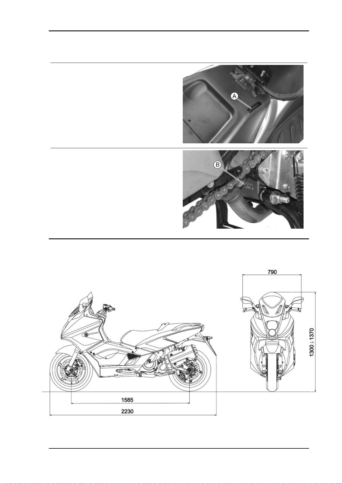
Vehicle identification
Chassis prefix (A):
ZAPM55100
Engine prefix (B):
M554M
Dimensions and mass
CHAR - 3
Page 10

Characteristics GP 800 i.e.
WEIGHTS AND DIMENSIONS
Specification Desc./Quantity
Kerb weight 248 ± 10 kg
Maximum weight allowed 450 kg
Maximum height 1300 ÷ 1370 mm
Width 790 mm
Wheelbase 1585 mm
Length 2230 mm
Engine
ENGINE
Specification Desc./Quantity
Type 90° V-twin engine, 4-stroke, with double spark plug
Cubic capacity 839 cm3
Bore x stroke 88 x 69 mm
Compression ratio 10.5 ± 0.5 : 1
Engine idle speed 1,250 ± 100 rpm
Timing system 4 valves, single overhead camshaft, driven.
Valve clearance Inlet: 0.15 mm
Outlet: 0.15 mm
MAX. Power 50.5 kW at 7,750 rpm
MAX. torque 71 Nm at 4,500 rpm
Lubrication Engine lubrication by a dry sump system, with
double lobe pump (one for delivery and one for re-
turn), controlled by a chain and paper filter.
Lubrication pressure 3.5 ÷ 4 bar
Minimum lubrication pressure (100° C) 0.8 bar
Fuel supply Multipoint electronic injection with single Ø 38-mm
throttle body and electric fuel pump.
Cooling Forced liquid circulation cooling.
Fuel Unleaded petrol (95 RON)
TECHNICAL SPECIFICATIONS
Specification Desc./Quantity
Type Trochoidal
Rotor washers Delivery pump: 12 mm
Assembly clearances Lobe ends: 0.04 ÷ 0.1 mm
External rotor radial clearance 0.05- 0.12 mm
Levelness 0.1 mm
Specification Desc./Quantity
Type with piston
Plunger diameter Ø 14-0.016 -0.043 mm
Unloaded spring length 52 mm
Calibration pressure 4.5 bar
CHAR - 4
OIL PUMP
Scavenge pump: 22 mm
BY-PASS
Page 11

GP 800 i.e. Characteristics
OIL FILTER
Specification Desc./Quantity
Type Paper with pressure relief and anti-drain back by-
pass valves
OIL MINIMUM PRESSURE INDICATOR LIGHT SWITCH
Specification Desc./Quantity
Calibration 0.3 - 0.6 bar
HEAD LUBRICATION CONTROL JET
Specification Desc./Quantity
Diameter 1 ± 0.05 mm *
* Tightening torque 5÷7 N·m
PISTON COOLING NOZZLE
Specification Desc./Quantity
Diameter Ø 1 ± 0.05 mm
CRANKCASE VENTILATION CHECK
Specification Desc./Quantity
Device metal reed valve and decantation chamber
TECHNICAL SPECIFICATIONS
Specification Desc./Quantity
Cooling system capacity 2.4 l
Prescribed fluid AGIP PERMANENT SPEZIAL
Sealing pressure Cap calibrated at 0.9 bar
THERMOSTAT
Specification Desc./Quantity
Type Wax-type, with deviator
Starts opening 85±2°C
ELECTRIC VENTILATION
Specification Desc./Quantity
Type With piston
Electric ventilation starts at 105°C
Electric ventilation stops at 100°C
WATER PUMP
Specification Desc./Quantity
Type Centrifugal
Control Gear on oil delivery pump
RADIATOR
Specification Desc./Quantity
Type Aluminium, with horizontal circulation
CHAR - 5
Page 12
Characteristics GP 800 i.e.
EXPANSION TANK
Specification Desc./Quantity
Calibration Automatic bleeding, in parallel with the radiator
Transmission
TRANSMISSION
Specification Desc./Quantity
Main drive Automatic expandable pulley variator with torque
server, V-belt, automatic dry self-ventilating
clutch.
Secondary reduction
Final transmission Chain-driven
Gear reduction unit in oil bath.
Capacities
CAPACITY
Specification Desc./Quantity
Engine oil 2.5 l (without oil filter replacement)
Transmission oil ~ ----- cm³
Cooling system fluid ~ 2.4 l
Fuel tank (reserve) ~14 l ± 0.5 l (~1.8 l)
Electrical system
ELECTRICAL SYSTEM
Specification Desc./Quantity
Start-up Electric
Ignition High efficiency electronic inductive ignition, inte-
Ignition advance Three-dimensional map managed by control unit
Spark plug NGK CR7EKB
Alternative spark plug -
Battery 12 V / 14 Ah, SEALED BATTERY
Generator Three-phase alternating current, 450W.
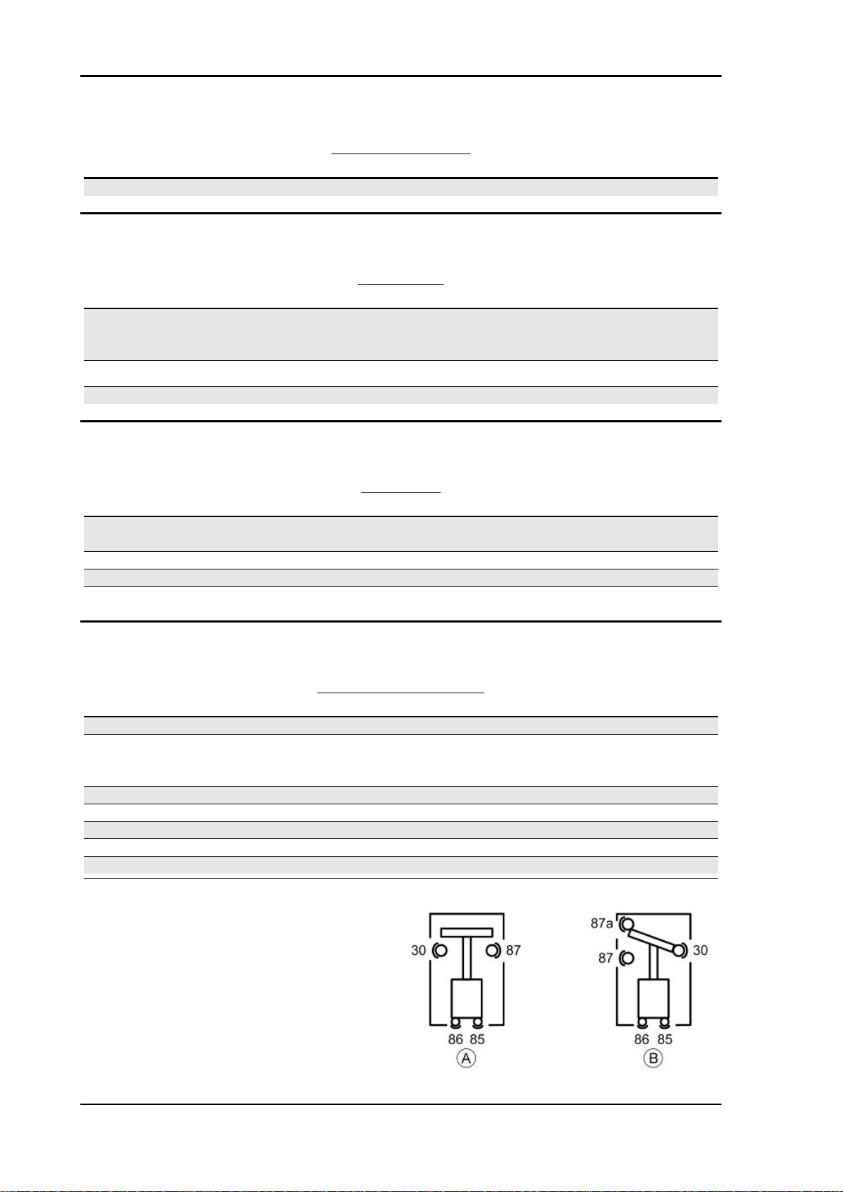
There are two types of remote controls in the elec-
2.6 l (with oil filter replacement)
grated with the injection system, with variable ad-
vance and separate HV coil.
trical system, those operating as "circuit breakers"
«A», and those operating as a "switches" «B».
CHAR - 6
Page 13
GP 800 i.e. Characteristics
CHECKING REMOTE CONTROLS «A» OPERATING AS CIRCUIT BREAKERS
1) Check that, given regular conditions, there is no
continuity between terminals 30 and 87.
2) Apply 12V voltage to power terminals 85 and 86
of the remote control.
3) With the remote control powered, check that
there is continuity between terminals 30 and 87.
4) If these conditions are not fulfilled, the remote
control is damaged and must be replaced.
CHECKING REMOTE CONTROLS «B» OPERATING AS SWITCHES
1) Check that, given regular conditions, there is no
continuity between terminals 30 and 87 but that
there is continuity between terminals 30 and 87a.
2) Apply 12V voltage to power terminals 85 and 86
of the remote control.
3) With the remote control powered, check that
there is continuity between terminals 30 and 87.
However, there must be no continuity between terminals 30 and 87a.
4) If these conditions are not fulfilled, the remote
control is damaged and must be replaced.
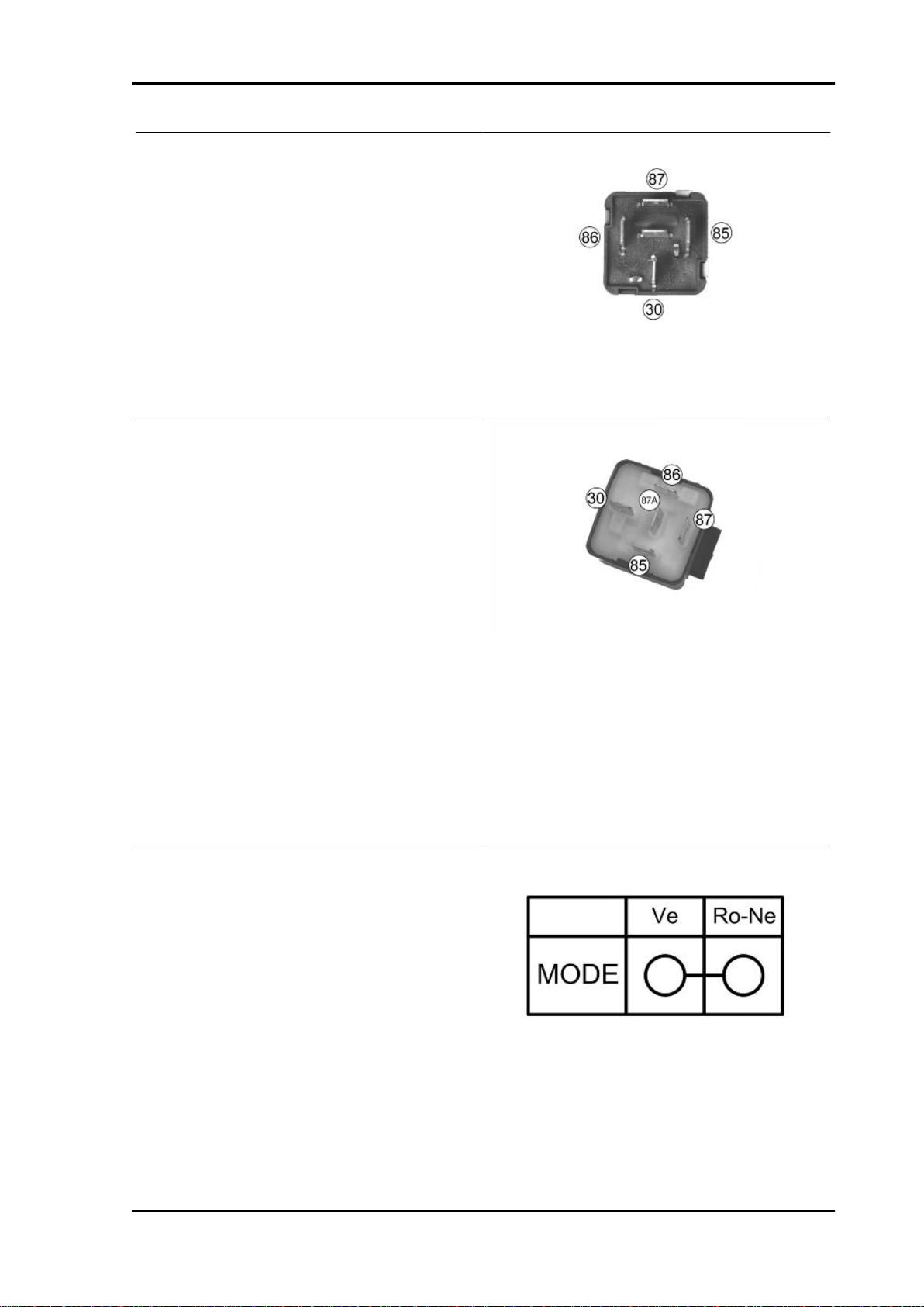
To check buttons and switches make sure that, according to their position, the continuity of contacts is
correct, as indicated in the following tables.
«MODE» BUTTON
CHAR - 7
Page 14
Characteristics GP 800 i.e.
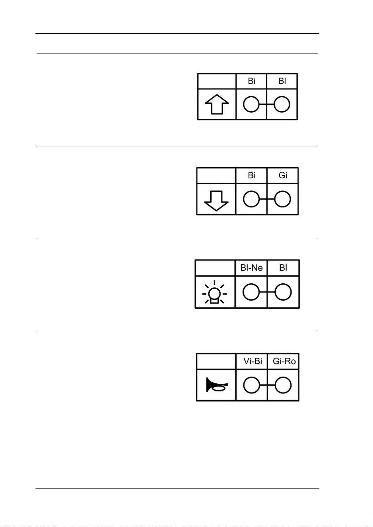
WINDSHIELD «UP» BUTTON
WINDSHIELD «DOWN» BUTTON
HELMET COMPARTMENT LIGHT BUTTON
HORN BUTTON
CHAR - 8
Page 15
GP 800 i.e. Characteristics
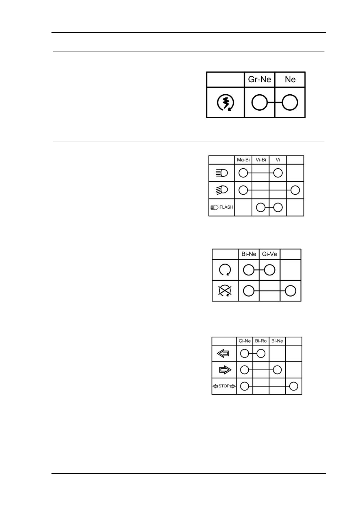
STARTER BUTTON
LIGHT SWITCH
ENGINE STOP SWITCH
TURN INDICATOR SWITCH
CHAR - 9
Page 16
Characteristics GP 800 i.e.
INTAKE AIR TEMPERATURE SENSOR
-10° = 9600 Ohm
0° = 5900 Ohm
+10° = 3800 Ohm
+20° = 2500 Ohm
-30° = 1700 Ohm
THROTTLE POSITION SENSOR
With the switch set to "ON" at a variable voltage
between 0.7V and > 4V between pins 23 - 3 on
engine-side wiring.
Ground insulation of pins 29 - 32 - 3 on engine-side
wiring
STEPPER MOTOR
Resistance engine-side connector between pins
19 - 9 ~ 51 Ohm
Resistance engine-side connector between pins
18 - 17 ~ 51 Ohm
FUEL INJECTOR
Type: 4 holes
Conicity of the nozzle: 24°
Resistance at terminals: 13.7 ÷ 15.2 Ohm
CHAR - 10
Page 17
GP 800 i.e. Characteristics
FUEL PUMP UNIT
Mechanical type pressure regulator operating at a
pressure of 3 BAR
Pump winding resistance: ~ 1,5 Ohm
REVOLUTION TIMING SENSOR
Resistance between "+ and -" = 890 ± Ohm (pins
35 - 25 , engine-side wiring)
Insulation between "+ and S" and between "- and
S" (pins 35 - 34 and 25 - 34, engine-side wiring)
ENGINE TEMPERATURE SENSOR
0° = 5900 Ohm
+10° = 3800 Ohm
+20° = 2500 Ohm
+30° = 1700 Ohm
+80° = 300 Ohm
H.V. COIL
Primary winding resistance: 520 ÷ 620 mOhm
Secondary resistance: 6830 ÷ 7830 Ohm
CHAR - 11
Page 18
Characteristics GP 800 i.e.
MINIMUM OIL PRESSURE SENSOR
Normally closed switch
Activation threshold: 0.3 - 0.6 bar
With the engine off: continuity between terminal
and ground
STATOR
Resistance between terminals: 0.2 ÷ 1 Ohm
Terminal insulation from ground
Frame and suspensions
Specification Desc./Quantity
Chassis Double cradle with tubular and steel stamped
Front suspension Hydraulic telescopic fork, single plate, ø 41-mm
Front suspension travel 126 mm
Oil quantity for stem 295 ± 3 cm³
Unloaded spring length ----- mm
Rear suspension Single shock absorber that acts directly on the
Rear suspension travel 135 mm
Brakes
Specification Desc./Quantity
Front brake Ø 300-mm double disc brake with hydraulic control
Rear brake Ø 280-mm disc brake, with hydraulic servo oper-
FRAME AND SUSPENSIONS
plates
straight stems.
fork.
BRAKES
activated by the handlebar right-hand lever.
Two floating callipers, ø 28 double plunger
ated from the handlebar with the left-hand lever.
One floating calliper with a single plunger
CHAR - 12
Page 19

GP 800 i.e. Characteristics
Wheels and tyres
WHEELS AND TYRES
Specification Desc./Quantity
Wheel rim type Light alloy rims.
Front rim 16'' x 3.50
Rear rim 15'' x 4.50
Front tyre Tubeless, 120/70 - 16" 57H
Rear tyre Tubeless, 160/60 - 15" 67H
Front tyre pressure (with passenger) 2.5 bar (-)
Rear tyre pressure (with passenger) 2.75 bar (-)
Tightening Torques
LUBRICATION
Name Torque in Nm
Engine oil drainage plug 21 ÷ 29
Bulkhead screws for oil pump housing cover 3 ÷ 4
Engine oil filter 12 - 16
Oil pump chain tensioner pad 2 ÷ 3
Oil pump screws 5 - 6
By-pass scavenge duct fixing screws 11 ÷ 13
Lubrication circuit upper bulkhead 3 ÷ 4
Oil pump crown screw 10 ÷ 14
Screws fixing oil pump to the crankcase 5 - 6
Minimum oil pressure sensor 10
Water pump gear fixing screw 5 - 6
THERMAL GROUP AND TIMING SYSTEM
Name Torque in Nm
Spark plug 12 ÷ 14
Head fixing stud bolts: ***
Head fixing nuts 10 - 12
Exhaust / intake head fixing nuts: 10 - 12
Head lubrication control jet 5 - 7
Tensioner sliding block fixing screw: 10 - 14
injector fixing screw 3 ÷ 4
inlet manifold fixing screws 11 - 13
Tappet cover fixing screws: 7 - 9
Throttle body fixing screws 11 ÷ 13
camshaft retaining bracket fixing screws 4 - 6
Head fixing screws 10 - 12
Coolant temperature sensor 21 ÷ 23
Revolution timing sensor fixing screw 7.5 ÷ 8.5
Timing system chain tensioner screw 11 ÷ 13
Timing system gear on camshaft screw 12 ÷ 14
*** Apply a preliminary torque of 10 Nm in a criss-crossed sequence. - tighten with a torque of 13 Nm
+ 90° in a criss-crossed sequence. - tighten again by 90° in a criss-crossed sequence.
TRANSMISSION COVER
Name Torque in Nm
Drive pulley nut 252 ÷ 278
CHAR - 13
Page 20

Characteristics GP 800 i.e.
Name Torque in Nm
Driven pulley nut 153 ÷ 187
Clutch ring nut 65 - 75
External transmission cover screws 5 ÷ 7
Internal transmission cover screws 11 ÷ 13
Air switch screw 3 ÷ 4
Air outlet grille screws 3 ÷ 4
FLYWHEEL COVER
Name Torque in Nm
Flywheel fixing nut 116 ÷ 128
Stator retainers 8 - 10
Screw fixing freewheel to flywheel 13 ÷ 15
Flywheel cover screws 11 - 13
CRANKCASE AND CRANKSHAFT
Name Torque in Nm
Starting ring gear retaining plate 3 ÷ 4
Engine crankcase coupling screws (M6) 11 ÷ 13
Engine crankcase coupling screws (M8) 25 ÷ 28
COOLING
Name Torque in Nm
Water pump rotor cover 3 ÷ 4
bleed screw 3 ÷ 4
Water pump impeller 4 ÷ 5
Screws tightening water pump gear protection
plate
3 ÷ 4
CHASSIS
Name Torque in Nm
Side stand bolt nut 37
Screws fixing side stand button 6
Screw fixing electric fan - radiator 2 ÷ 3
Screw fixing radiator - chassis 5 ÷ 7
Nut fixing silent-block plate - chassis 22 ÷ 25
Nut fixing silent-block plate 33 ÷ 41
Pin fixing nut - M14 124 ÷ 153
Pin fixing nut - M10 47 ÷ 52
Upper nut fixing engine support link rods - chassis 33 ÷ 41
Lower nut fixing engine support link rods - chassis 33 ÷ 41
Nut fixing head - exhaust manifold 16 ÷ 18
Centre stand front bolt nut 34 ÷ 39
Centre stand rear bolt nut 74 ÷ 81
Screw fixing silencer - muffler support arm 11
Screw fixing catalytic converter - catalytic convert-
er support
Screw fixing muffler support arm - engine 24 ÷ 27
Silencer fixing screw 22
Manifold retainer clamp 16 ÷ 18
22 ÷ 24
CHAR - 14
Page 21

GP 800 i.e. Characteristics
PINION UNIT
Name Torque in Nm
Screw for plate locking pinion driving bushing 4 ÷ 6*
Screws fixing pinion unit cover 4 ÷ 5*
Screws fixing pinion unit - chassis 50
Pinion unit oil drain screw 13 ÷ 15
Pinion unit oil filling screw 13 ÷ 15
Oil sealing casing clamp 3 ÷ 5
(*) Apply LOCTITE 243 threadlock
HANDLEBAR
Name Torque in Nm
Screws fixing handlebar supporting plate - steer-
ing tube
Screws fixing frame - supporting plate 4.5 ÷ 7
Screws fixing half-handlebars - supporting plate 20 ÷ 25*
Screw fixing half-handlebar insert - half-handlebar 20 ÷ 25*
Handlebar cover fixing screw 2.5 ÷ 4
Brake pump stand fixing screws 7 ÷ 10
(*) Apply LOCTITE 243 threadlock
50 ÷ 55
MISCELLANEOUS
Name Torque in Nm
starter motor retainers 11 - 13
BRAKE SYSTEM
Name Torque in Nm
Brake pipes / rear brake calliper coupling 20 ÷ 25
Brake pipes / brake pump coupling 16 ÷ 20
Screws fixing front brake disc to rim 25
Screws fixing rear brake disc to rim 25
Screws fixing brake pump to handlebar 7 ÷ 10
Screw fixing three-way union to fork head 10 ÷ 12
Screws fixing front brake calliper to fork 20 ÷ 25
Screw fixing rear brake calliper to supporting plate 20 ÷ 25
Screw fixing parking brake calliper to supporting
plate
Brake calliper bleed screw 4 ÷ 7
Parking brake adjusting nut 10
Nut fixing rear brake pipe retaining clip 11 ÷ 13
Pin fixing parking brake pads 15 ÷ 20
Brake pipes / three-way union coupling 18 ÷ 23
Brake pipes / front brake calliper coupling 16 ÷ 20
Rear brake pad fixing pins 15 ÷ 20
24 ÷ 27
FRONT SUSPENSION
Name Torque in Nm
Screw fixing wheel pin on right fork leg 6 ÷ 7
Front wheel pin nut 60 ÷ 70
Hydraulic rod fixing screw 25 ÷ 35*
Fork locking screws cap 35 - 55
Stem support clamp tightening screws 20 ÷ 25
CHAR - 15
Page 22
Characteristics GP 800 i.e.
Name Torque in Nm
Steering tube lower ring nut 20 ÷ 22
Steering tube upper ring nut 48 ÷ 54
(*) Apply LOCTITE 243 threadlock
REAR SUSPENSION
Name Torque in Nm
Nut fixing shock absorber - fork 38 - 46
Screw fixing shock absorber - fork 38 - 46
Screw fixing chain stop slider - fork 5 ÷ 7
Screw fixing centre stand stop buffer - fork 5 ÷ 7
Crown fixing screws 22.5 ÷ 27.5*
Rear wheel pin nut 70
Fork locking ring nut 60 ± 3 Nm
Fork pin set screw 0.5
Fork pin nut 90 ± 5
(*) Apply LOCTITE 243 threadlock
Overhaul data
Assembly clearances
Cylinder - piston assy.
CHAR - 16
Page 23
GP 800 i.e. Characteristics
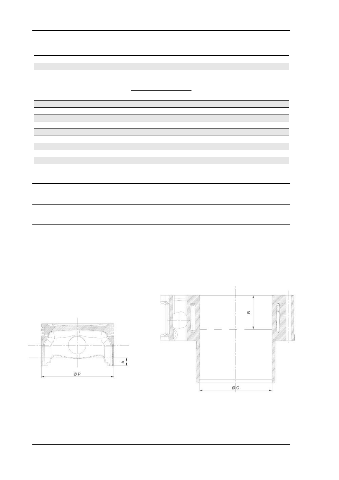
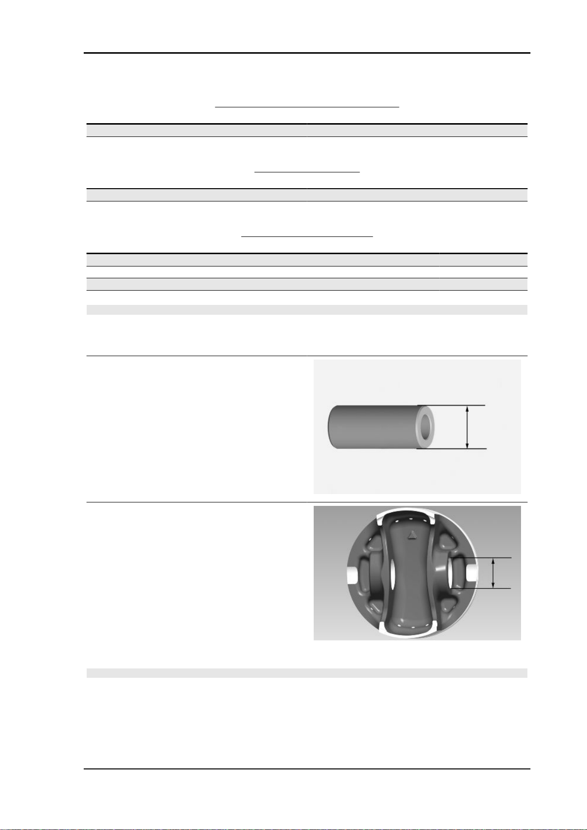
HEIGHT TO MEASURE THE PISTON
Specification Desc./Quantity
A 10 mm
B 43 mm
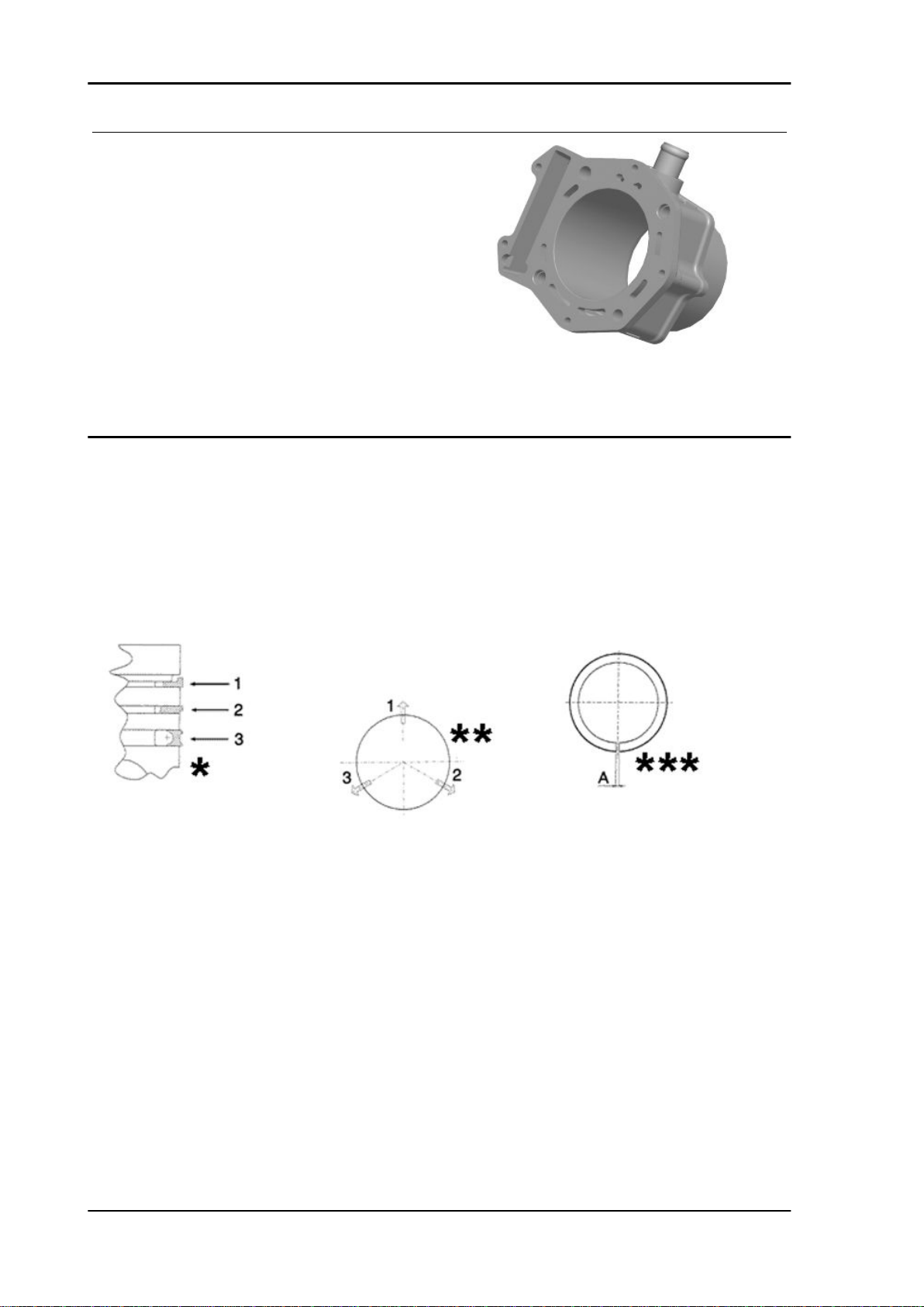
CYLINDER - PISTON
Specification Desc./Quantity
Cylinder diameter C 88 +0.018-0.01 mm
Piston Ø P 87.968 ±0.014 mm
COUPLING CATEGORIES
Name Initials Cylinder Piston Play on fitting
Cylinder- Piston A 87.990÷87.997 87.954÷87.961 0.029÷0.043
Cylinder- Piston B 87.997 ÷ 87.004 87.961 ÷ 87.968 0.029÷0.043
Cylinder- Piston C 88.004÷88.011 87.968÷87.975 0.029÷0.043
Cylinder- Piston D 88.011÷88.018 87.975 ÷ 87.982 0.029÷0.043
N.B.
THE PISTON MUST BE INSTALLED WITH THE ARROW FACING TOWARDS THE EXHAUST SIDE,
THE PISTON RINGS MUST BE INSTALLED WITH THE WORD «TOP» OR THE STAMPED MARK
FACING UPWARDS.
- Calculate the coupling clearance between pin
and connecting rod end.
Characteristic
Standard clearance:
0.015 ÷ 0.029 mm
- Measure the capacity diameter on the piston.
Characteristic
Standard diameter:
22 + 0.006 + 0.001 mm
- Calculate the piston pin coupling clearance.
N.B.
THE PIN HOUSINGS HAVE 2 LUBRICATION CHANNELS. FOR THIS REASON, MEASUREMENT
MUST BE MADE ACCORDING TO THE PISTON AXIS.
Characteristic
Standard clearance:
0.001 ÷ 0.010 mm
CHAR - 17
Page 24
Characteristics GP 800 i.e.
- Check that coating is free from flakes.
- Check that the head matching surface exhibits no
deformations or wear.
Characteristic
Maximum allowable run-out:
0.05 mm
- Pistons and cylinders are classified into categories based on their diameter. The coupling is carried
out in pairs (A-A, B-B, C-C, D-D).
Piston rings
*Fit rings «2» and «3» with the word «TOP» facing upwards.
** Position the openings in the rings as shown here.
***Value «A» of sealing ring inside the cylinder.
Check the size of the sealing ring opening:
Compression ring: 0.15 ÷ 0.35 mm. Max. value 0.5 mm
Oil scraper ring: 0.25 ÷ 0.50 mm. Max. value 0.65 mm
Oil scraper ring: 0.25 ÷ 0.50 mm. Max. value 0.65 mm
CHAR - 18
Page 25
GP 800 i.e. Characteristics
Rings/housing coupling clearances:
Carefully clean the sealing ring housings.
Place a thickness gauge between the ring and the
housing as shown in the drawing and check the
coupling clearances.
Top ring Standard coupling clearance:
0.01÷0.06 mm
Maximum clearances allowed after use: 0.10
mm
Intermediate ring Standard coupling clearance:0.02÷0.07 mm
Maximum clearances allowed after use: 0.10
mm
Oil scraper ring Standard coupling clearance:
0.01÷0.06 mm
Maximum clearances allowed after use: 0.10
mm
Replace the piston if clearances exceed the maximum limits specified in the table.
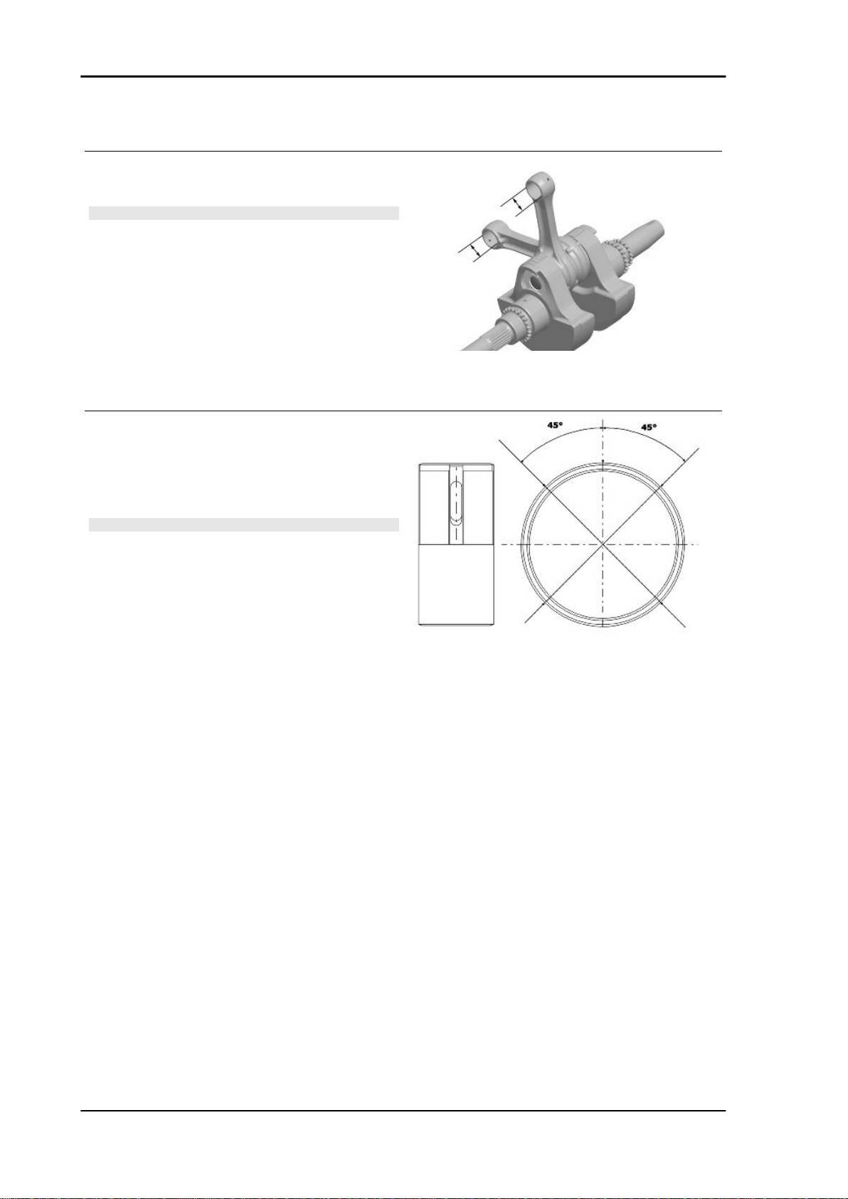
Crankcase - crankshaft - connecting rod
Diameter of crankshaft bearings.
Measure the capacity on both axes x-y.
CHAR - 19
Page 26
Characteristics GP 800 i.e.
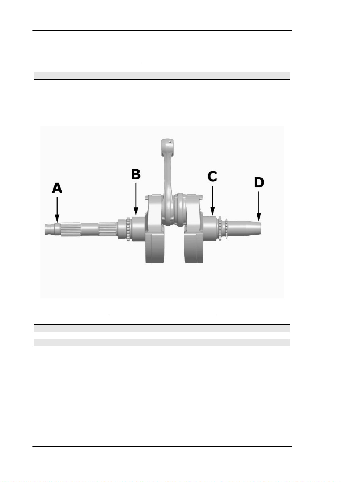
CRANKSHAFT
Specification Desc./Quantity
Cat. 1 Standard diameter: 45.010 ÷ 45.016
Cat. 2 Standard diameter: 45.016 ÷ 45.022
Crankshaft alignment
Specific tooling
020335Y Magnetic support for dial gauge
CHAR - 20
MAX. ADMISSIBLE DISPLACEMENT
Specification Desc./Quantity
A = 0.15 mm
B = 0.010 mm
C = 0.010 mm
D = 0.10 mm
Page 27

GP 800 i.e. Characteristics
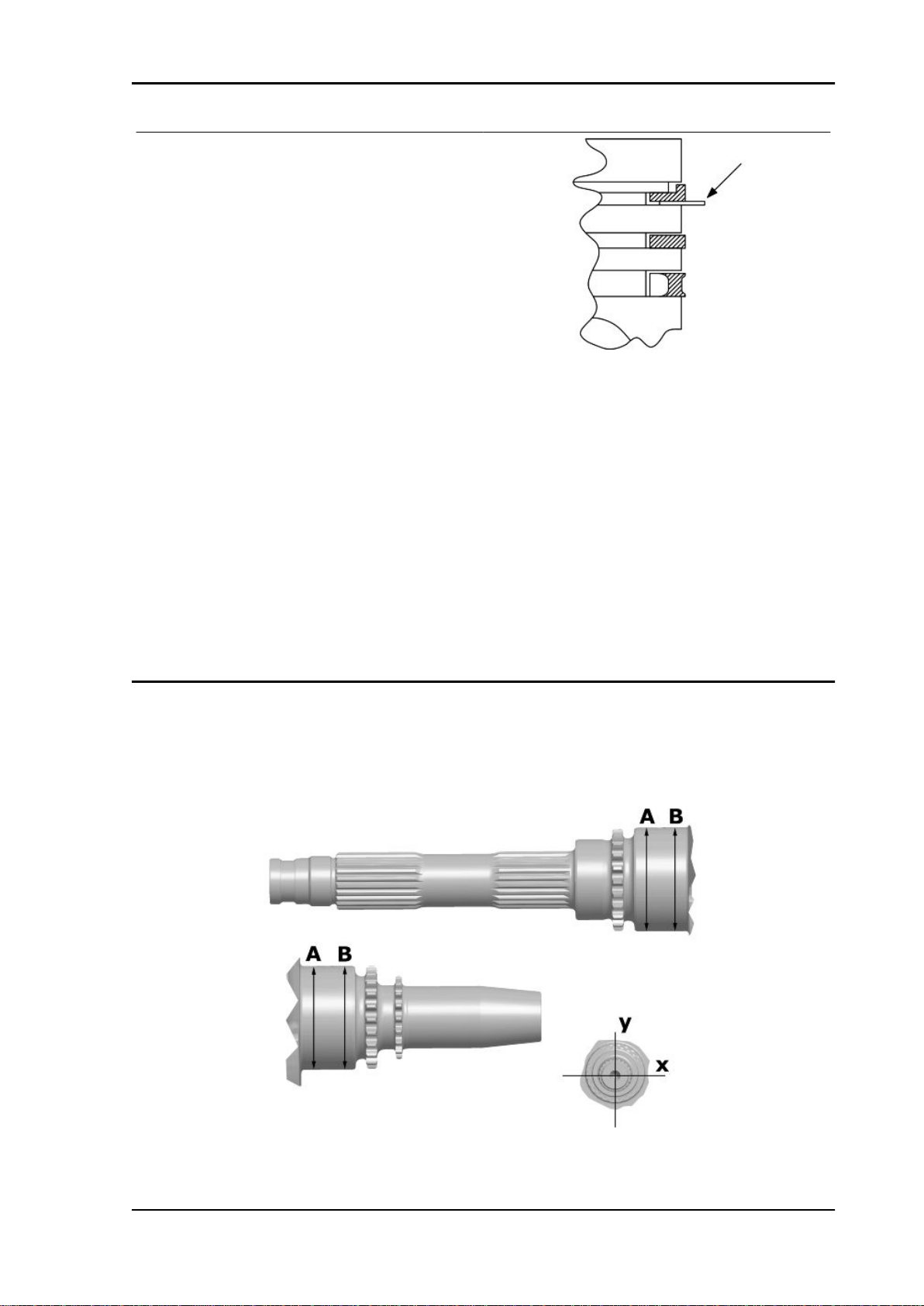
AXIAL CLEARANCE BETWEEN CRANKSHAFT AND CONNECTING ROD
Name Description Dimensions Initials Quantity
Half-shaft, trans-
mission side
Flywheel-side half-
shaft
Connecting rod 22 -0.10 - 0.15 C D = 0.20 ÷ 0.55
Complete crank-
shaft
23.8 +0.1 A D = 0.20 ÷ 0.55
23.8 + 0.1 B D = 0.20 ÷ 0.55
91.8 +0.05 E D = 0.20 ÷ 0.55
Characteristic
Crankshaft-crankcase axial clearance (H)
CHAR - 21
Page 28
Characteristics GP 800 i.e.
0.1 ÷ 0.45 mm (when cold)
- Using a bore gauge, measure the connecting rod
small end diameter.
N.B.
IF THE CONNECTING ROD SMALL END DIAMETER EXCEEDS THE STANDARD DIAMETER,
EXHIBITS WEAR OR OVERHEATING, PROCEED TO REPLACE THE CRANKSHAFT AS
DESCRIBED IN CHAPTER CRANKCASE AND
CRANKSHAFT.
Characteristic
Standard diameter:
22 + 0.025 +0.015 mm
- Check the inside diameter of the main bushings
in the three directions indicated in the diagram.
- Repeat the measurements for the other bushing
half. see diagram.
N.B.
DO NOT TAKE THE MEASUREMENT ON THE
TWO HALF-SHELL COUPLING SURFACE
SINCE THE ENDS ARE RELIEVED TO ALLOW
BENDING DURING THE DRIVING OPERATION.
Before assembling, check that the clearance between the engine crankcase bushing and the crankshaft
is within the predetermined limits.
Characteristic
Crankshaft-bushing maximum clearance admitted:
0.08 mm
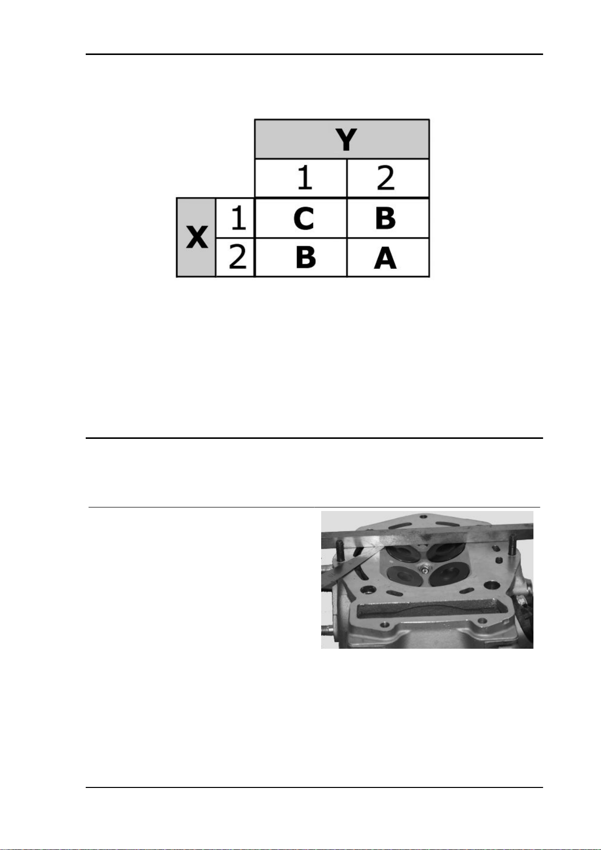
- The standard bushing diameter after driving is variable on the basis of a coupling selection.
- The bushing seats in the crankcase and the crankshaft are classified into 2 categories.
- Bushings are subdivided into 3 categories according to their thickness (see the table).
The following kinds of bushings indicated in the table must be used according to the kind of coupling
between the crankshaft and the crankcase.
CHAR - 22
Page 29
GP 800 i.e. Characteristics
KEY
X = Crankshaft category
Y = Crankcase half-shell category
A = Red
B = Blue
C = Yellow
Cylinder Head
Before performing head service operations, thoroughly clean all coupling surfaces. Note the position of
the springs and the valves so as not to change the original position during refitting
- Using a trued bar and feeler gauge check that the
cylinder head surface is not worn or distorted.
Characteristic
Maximum allowable run-out:
0.1 mm
- In case of irregularities, replace the head.
- Check the sealing surfaces for the intake and exhaust manifold.
- Check that the camshaft and the rocker pin capacities exhibit no wear.
- Check that the head cover surface is not worn.
- Check that the coolant sealing pad exhibits no oxidation.
CHAR - 23
Page 30
Characteristics GP 800 i.e.
- Insert the valves into the cylinder head.
- Alternatively check the intake and exhaust
valves.
- The test is carried out by filling the manifold with
petrol and checking that the head does not ooze
through the valves when these are just pressed
with the fingers.
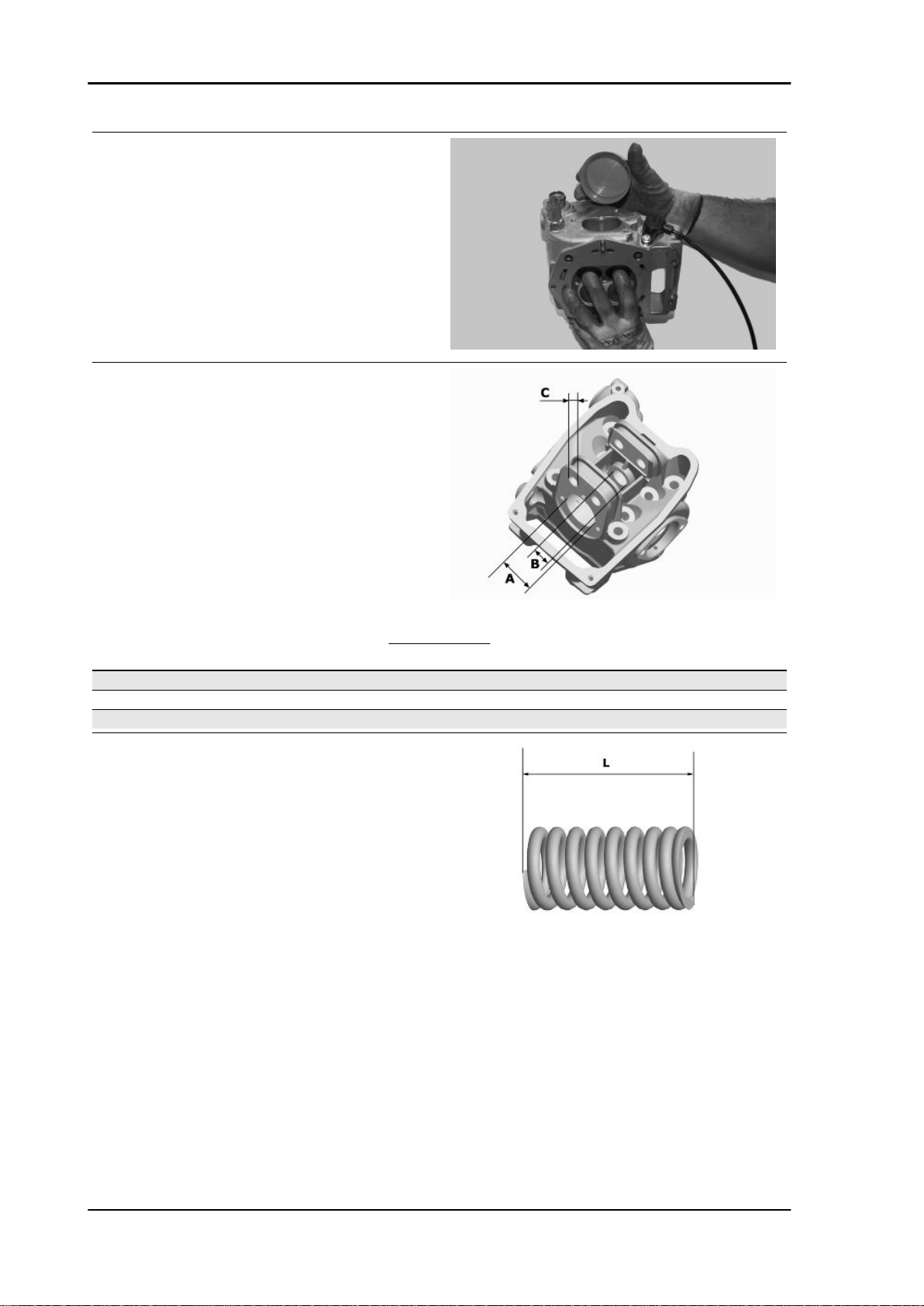
Measure the camshaft bearing seats and rocking
lever support pins with a bore meter
Specification Desc./Quantity
Bearing "A" 42 +0.025
Bearing "B" 19.5 -0.2
Bearing "C" 13 +0.018
- Measure the unloaded spring length.
Characteristic
Standard length:
44.4 mm
Admissible limit after use:
42.4 mm
HEAD BEARINGS
CHAR - 24
Page 31

GP 800 i.e. Characteristics
- Clean the valve seats of any carbon residues.
- Using the Prussian blue, check the width of the
impression on the valve seat "V".
Characteristic
Standard value:
1 - 1.3 mm
Admissible limit:
1.6 mm
- If the impression width on the valve seat is larger than the prescribed limits, true the seats with a 45°
mill and then grind.
- In case of excessive wear or damages, replace the head.
STANDARD VALVE LENGTH
Specification Desc./Quantity
Inlet: 95.0 ± 0.3 mm
Outlet: 94.2 ± 0.3 mm
- Measure the diameter of the valve stems in the three positions indicated in the diagram.
STANDARD DIAMETER
Specification Desc./Quantity
Inlet: 4.987 - 4.972 mm
Outlet: 4.975 - 4.960 mm
MINIMUM ADMISSIBLE DIAMETER
Specification Desc./Quantity
Inlet: 4.96 mm
Outlet: 4.945 mm
CHAR - 25
Page 32

Characteristics GP 800 i.e.
- Calculate the clearance between valve and valve
guide.
- Check the deviation of the valve stem by resting
it on a "V" shaped abutment and measuring the
extent of the deformation with a comparator.
Characteristic
Limit values admitted:
0.1 mm
- Check the concentricity of the valve head by arranging a comparator at right angle relative to the
valve head and rotate it on a "V" shaped abutment.
Characteristic
Admissible limit:
0.03 mm
Measure the valve guide.
Characteristic
Valve guide:
5 +0.012 mm
CHAR - 26
Page 33

GP 800 i.e. Characteristics
- After measuring the valve guide diameter and the
valve stem diameter, check the clearance between guide and stem.
OUTLET
Specification Desc./Quantity
Standard clearance: 0.025 ÷ 0.052 mm
Admissible limit: 0.09 mm
INLET
Specification Desc./Quantity
Standard clearance: 0.013 - 0.04 mm
Admissible limit: 0.08 mm
- Check that there are no signs of wear on the surface of contact with the articulated register terminal.
- If the checks above give no failures, you can use
the same valves. To obtain better sealing performance, grind the valve seats. Grind the valves gently
with a fine-grained lapping compound. During the
grinding, keep the cylinder head with the valve axes in a horizontal position. This will prevent the
lapping compound residues from penetrating between the valve stem and the guide (see figure).
CAUTION
TO AVOID SCORING THE CONTACT SURFACE, DO NOT KEEP ROTATING THE VALVE WHEN
NO LAPPING COMPOUND IS LEFT. CAREFULLY WASH THE CYLINDER HEAD AND THE
VALVES WITH A SUITABLE PRODUCT FOR THE TYPE OF LAPPING COMPOUND BEING USED.
CAUTION
CHAR - 27
Page 34

Characteristics GP 800 i.e.
DO NOT REVERSE THE FITTING POSITIONS OF THE VALVES (RIGHT - LEFT).
- Check that the camshaft ends exhibit no scores or irregular wear.
- Using a micrometer, measure the camshaft capacity.
STANDARD DIAMETER
Specification Desc./Quantity
Bearing A Ø: 42 - 0.060 -0.085 mm
Bearing B diameter: 20 - 0.020 -0.041 mm
MINIMUM ADMISSIBLE DIAMETER
Specification Desc./Quantity
Bearing A Ø: 41.910 mm
Bearing B diameter: 19.940 mm
-Using a gauge, measure the cam height.
STANDARD HEIGHT
Specification Desc./Quantity
intake 33.988 mm
discharge 33.417 mm
ADMISSIBLE LIMITS
Specification Desc./Quantity
intake 33.740 mm
discharge 33.170 mm
Standard axial clearance: 0 - 0.22 mm
Maximum admissible axial clearance: 0.3 mm
- Check that the cam contact sliding block and the articulated register plate is free from wear.
- In case of wear, replace the component.
CHAR - 28
Page 35

GP 800 i.e. Characteristics
- Check that the rocking lever pins exhibit no scores or wear.
Characteristic
Standard diameter:
13 - 0.010 -0.018 mm
- Measure the inside diameter of each rocking lever.
Characteristic
Standard diameter:
13 + 0.026 +0.015 mm
Slot packing system
Shimming system to control compression ratio
DISTANCE «A» IS A PROTRUSION OR RECESS VALUE OF THE PISTON CROWN WITH
RESPECT TO THE CYLINDER PLANE.
DISTANCE «A» HELPS DETERMINE THE
THICKNESS OF GASKET «B» THAT HAS TO
BE FITTED TO THE CYLINDER HEAD IN ORDER TO RESTORE COMPRESSION RATIO.
BASE GASKET «B» MUST BE THICKER THE
MORE THE PLANE FORMED BY THE PISTON
TOP PROTRUDES FROM THE PLANE
FORMED BY THE CYLINDER HEAD. ON THE
OTHER HAND, THE MORE THE PISTON TOP IS
RECESSED INTO THE CYLINDER TOP PLANE,
THE SMALLER THE GASKET THICKNESS.
Characteristic
Compression ratio
10.5 ± 0.5 : 1
BASE GASKET THICKNESS
Name Measure A Thickness
«A» MEASURE TAKEN - 0.185 - - 0.10 0.4 ± 0.05
«A» MEASURE TAKEN - 0.10 - + 0.10 0.6 ± 0.05
«A» MEASURE TAKEN + 0.10 ÷ + 0.185 0.8 ± 0.05
N.B.
VALUES INDICATED WITH «-» REFER TO PISTON CROWN RECESSES WITH RESPECT TO THE
CYLINDER PLANE.
N.B.
DISTANCE «A» MUST BE MEASURED WITHOUT ANY GASKET FITTED AT «B»
CHAR - 29
Page 36

Characteristics GP 800 i.e.
Products
RECOMMENDED PRODUCTS TABLE
Product Description Specifications
AGIP BRAKE 4 Brake fluid FMVSS DOT 4 Synthetic fluid
AGIP CITY HI TEC 4T Engine oil SAE 5W-40, API SL, ACEA A3,
JASO MA Synthetic oil
SPECIAL AGIP PERMANENT
fluid
AGIP GP 330 Grease for brake control levers,
AGIP GREASE PV2 Grease for steering bearings and
AGIP FORK 7.5 W Oil for front fork Hydraulic fluid SAE 7.5 W
AGIP ROTRA MP 80W-90 Transmission oil SAE 80W-90, API GL-5
AGIP CHAIN SPRAY Spray lubricating grease Spray lubricating grease for
coolant Monoethylene glycol-based anti-
freeze fluid, CUNA NC 956-16
White calcium complex soap-
throttle, stand
spindle seats
based spray grease with NLGI 2;
ISO-L-XBCIB2
Soap-based lithium and zinc ox-
ide grease containing NLGI 2;
ISO-L-XBCIB2 of the swinging
arm
chains and gears
UNIT OF MEASUREMENT - CONVERSION - ENGLISH SYSTEM AND INTERNATIONAL SYSTEM (IS).
Specification Desc./Quantity
1 Inch (in) 25.4 Millimetres (mm)
1 Foot (ft) 0.305 Meter (m)
1 Mile (mi) 1.609 Kilometre (km)
1 US Gallon (US gal) 3.785 Litre (l)
1 Pound (lb) 0.454 Kilogram (Kg)
1 Cubic inch (in³) 16.4 Cubic centimetres (cm³)
1 Foot pound (ft lb) 1.356 Newton meter (Nm)
1 Miles per hour (mi/h) 1.602 Kilometres per hour (km/h)
1 Pound per square inch (PSI) 0.069 (bar)
1 Fahrenheit (°F) 32+(9/5) Celsius (°C)
CHAR - 30
Page 37

INDEX OF TOPICS
TOOLING TOOL
Page 38

Tooling GP 800 i.e.
APPROPRIATE TOOLS
Stores code Description
001330Y Tool for fitting steering seats
001330Y014 Tool for fitting steering seats
001330Y015 Tool for fitting steering seats
020004Y Punch for removing fifth wheels
from headstock
020668Y Steering ring nut wrench
020306Y Punch for assembling valve seal
rings
TOOL - 2
020382Y012 bush (valve removing tool)
Page 39

GP 800 i.e. Tooling
Stores code Description
020431Y Valve oil seal extractor
020128Y Piston fitting band
020470Y Pin retainers installation tool
020475Y Piston position checking tool
020512Y Piston fitting fork
020478Y Punch for driven pulley roller cas-
ing
TOOL - 3
Page 40

Tooling GP 800 i.e.
Stores code Description
020565Y Flywheel lock calliper spanner
020659Y Tool to remove clutch and re-
place belt
020660Y Driving pulley lock
020713Y Flywheel extractor
020527Y Engine support base
020658Y Engine plate
TOOL - 4
Page 41

GP 800 i.e. Tooling
Stores code Description
020664Y Flywheel side crankshaft fitting
tip
020665Y Transmission side crankshaft fit-
ting tip
020709Y Engine support
020460Y Scooter diagnosis and tester
020469Y Reprogramming kit for scooter
diagnosis tester
020661Y Water pump overall seal replace-
ment kit
TOOL - 5
Page 42

Tooling GP 800 i.e.
Stores code Description
020663Y Water pump shaft oil seal punch
020193Y Oil pressure gauge
020434Y Oil pressure control fitting
020480Y Petrol pressure check set
020331Y Digital multimeter
TOOL - 6
Page 43

GP 800 i.e. Tooling
Stores code Description
020648Y Single battery charger
002465Y Pliers for circlips
020621Y HV cable extraction adaptor
020330Y Stroboscopic light for timing con-
trol
020335Y Magnetic support for dial gauge
TOOL - 7
Page 44

Tooling GP 800 i.e.
Stores code Description
020262Y Crankcase splitting strip
001467Y007 Driver for OD 54 mm bearing
001467Y031 Bell
001467Y035 Belle for OD 47-mm bearings
001467Y002 Driver for OD 73 mm bearing
020329Y MityVac vacuum-operated pump
TOOL - 8
Page 45

GP 800 i.e. Tooling
Stores code Description
020150Y Air heater support
020151Y Air heater
001467Y003 Nut
001467Y004 Lug / Taper pin
001467Y005 Screw
001467Y006 Pliers to extract 20 mm bearings
020467Y020 Pliers to extract 30 mm bearings
TOOL - 9
Page 46

Tooling GP 800 i.e.
Stores code Description
001467Y001 Pliers to extract 25 mm Ø bear-
ings
001467Y008 Pliers to extract 17 mm ø bear-
ings
001467Y014 Pliers to extract ø 15-mm bear-
ings
020357Y 32 x 35 mm adaptor
020358Y 37x40-mm adaptor
020359Y 42x47-mm adaptor
020360Y Adaptor 52 x 55 mm
020655Y Adaptor 62x68 mm
TOOL - 10
020670Y Adaptor 34 mm
Page 47

GP 800 i.e. Tooling
Stores code Description
020375Y Adaptor 28 x 30 mm
020364Y 25-mm guide
020412Y 15 mm guide
020439Y 17 mm guide
020483Y 30 mm guide
TOOL - 11
Page 48

Tooling GP 800 i.e.
Stores code Description
020654Y 35 mm guide
020662Y 50 mm guide
020376Y Adaptor handle
020667Y Wrench for fork pin adjustment
ring nut
020632Y 22-mm Hexagonal spanner
020633Y Clamp for sealing ring driving of
Kayaba 41-mm and Marzocchi
40-mm forks
TOOL - 12
Page 49

INDEX OF TOPICS
MAINTENANCE MAIN
Page 50

Maintenance GP 800 i.e.
Follow these steps to reset the service icons:
1. With the key set to OFF, hold down the
"SET" button and turn the key to ON : the
"BELT" and "SERVICE" icons start flashing.
2. Push the "CLOCK" button for less than 1
second and the icons are displayed sequentially. The icon selected remains ON and the
other is no longer displayed.
3. Press the "CLOCK" button again for more
than 3 seconds to reset the relative maintenance step and the icon is no longer displayed.
Maintenance chart
MAINTENANCE TABLE
● Replacement
■ Check
* (Nominal: 0,15 mm INT and EXH) restore only if deviation exceeds 0.05 mm
** Replace every two years
Km x 1000 1 5 10152025303540455055606570758085909510
Engine Oil ● ● ● ● ● ● ● ● ● ● ●
Engine Oil - level check and
top-up
Oil filter ● ● ● ● ●
CVT driving belt ● ● ● ● ●
Slide pads and variator rollers ● ● ● ● ● ● ● ● ● ●
Ignition spark plugs ● ● ● ● ●
CVT air filter (sponge-mesh)
cleaning
Air filter ■ ● ■ ● ■ ● ■ ● ■ ●
Throttle body (cleaning) ■ ■ ■
ECU software upgrade ■ ■ ■
Valve clearance * ■ ■ ■
Pinion supporting unit oil ■ ● ● ● ● ● ● ● ● ● ●
Final transmission (lubrica-
tion)
Final transmission ● ● ● ● ●
Brake pads ■ ■ ■ ■ ■ ■ ■ ■ ■ ■ ■ ■ ■ ■ ■ ■ ■ ■ ■ ■ ■
Safety locks ■ ■ ■ ■ ■ ■
Throttle control - (adjustment) ■ ■ ■ ■ ■ ■ ■ ■ ■ ■ ■
Electrical system and battery ■ ■ ■ ■ ■ ■ ■ ■ ■ ■ ■
Coolant level ** ■ ■ ■ ■ ■ ■ ■ ■ ■ ■ ■
Brake fluid level ■ ■ ■ ■ ■ ■ ■ ■ ■ ■ ■
Tyre pressure and wear ■ ■ ■ ■ ■ ■ ■ ■ ■ ■ ■
Steering ■ ■ ■ ■ ■ ■ ■ ■ ■ ■ ■
■ ■ ■ ■ ■ ■ ■ ■ ■ ■
■ ■ ■ ■ ■
■ ■ ■ ■ ■ ■ ■ ■
0
MAIN - 2
Page 51

GP 800 i.e. Maintenance
Km x 1000 1 5 10152025303540455055606570758085909510
0
Suspensions ■ ■ ■ ■ ■ ■ ■ ■ ■ ■
Centre stand ■ ■ ■ ■ ■ ■ ■ ■ ■ ■ ■ ■ ■ ■ ■ ■ ■ ■ ■ ■ ■
Vehicle road test ■ ■ ■ ■ ■ ■ ■ ■ ■ ■ ■
Checking the spark advance
See also
Refitting the timing chain
Spark plug
To replace the rear cylinder spark plugs:
- Tip the saddle forwards, undo the five screws
«A» and remove cover «B».
- Disconnect caps «C» of the HV wire of the spark
plugs.
- Unscrew the spark plugs using the wrench supplied.
- Upon refitting, place the spark plugs into the hole at the due inclination and tighten them by hand.
- Only use the wrench to lock spark plugs in place.
- Place caps «C» fully over the spark plugs.
- Refit cover «B».
CAUTION
SPARK PLUGS MUST BE REMOVED WHEN THE ENGINE IS COLD. SPARK PLUGS MAINTENANCE OPERATIONS ARE DESCRIBED IN THE SCHEDULED MAINTENANCE TABLE. USING
NON-CONFORMING ELECTRONIC CENTRAL UNITS AND ELECTRONIC IGNITIONS OR SPARK
PLUGS OTHER THAN THOSE PRESCRIBED MAY SERIOUSLY DAMAGE THE ENGINE.
N.B.
THE USE OF SPARK PLUGS OTHER THAN THE INDICATED TYPE OR OF SHIELDLESS SPARK
PLUG CAPS CAN CAUSE ELECTRICAL SYSTEM FAILURES.
MAIN - 3
Page 52

Maintenance GP 800 i.e.
To replace the front cylinder spark plugs:
- Undo screw «D» and remove lid «E».
- Disconnect caps «F» of the HV wire of the spark
plugs.
- Unscrew the spark plugs using the wrench supplied.
- Upon refitting, place the spark plugs into the hole at the due inclination and tighten them using the
supplied spark plug wrench.
- Tighten the two spark plugs.
- Place caps «F» fully over the spark plugs.
- Refit the lid «E».
CAUTION
SPARK PLUGS MUST BE REMOVED WHEN THE ENGINE IS COLD. SPARK PLUGS MAINTENANCE OPERATIONS ARE DESCRIBED IN THE SCHEDULED MAINTENANCE TABLE. USING
NON-CONFORMING ELECTRONIC CENTRAL UNITS AND ELECTRONIC IGNITIONS OR SPARK
PLUGS OTHER THAN THOSE PRESCRIBED MAY SERIOUSLY DAMAGE THE ENGINE.
N.B.
THE USE OF SPARK PLUGS OTHER THAN THE INDICATED TYPE OR OF SHIELDLESS SPARK
PLUG CAPS CAN CAUSE ELECTRICAL SYSTEM FAILURES.
Characteristic
Spark plug
NGK CR7EKB
Electrode gap
0.7 ÷ 0.9 mm
MAIN - 4
Page 53

GP 800 i.e. Maintenance
Air filter
- Rimuovere la copertura laterale telaio da entrambi i lati del veicolo.
- Rimuovere la copertura centrale anteriore.
- Operando dal lato destro del veicolo, svitare la
vite indicata.
- Disimpegnare dalla fascetta di ritegno la tubazione blow-by.
- Operando dal lato sinistro del veicolo, svitare le
sei viti indicate e rimuovere la fascetta di ritegno
del manicotto.
- Rimuovere l'elemento filtrante dalla parte interna
del depuratore aria.
- Sfilare la tubazione di recupero vapori blow-by.
MAIN - 5
Page 54

Maintenance GP 800 i.e.
- Rimuovere la parte esterna del depuratore aria.
- Disimpegnare da entrambi i lati del veicolo gli occhielli della molla di chiusura e rimuoverla.
- Ruotare la parte interna del depuratore aria in
modo da disimpegnare l'incastro sul telaio.
- Rimuovere la parte interna del depuratore aria.
MAIN - 6
Page 55

GP 800 i.e. Maintenance
To access the air filter:
- Tip the saddle forwards, undo the five screws
«A» and remove cover «B».
- Remove the battery compartment access cover
«C» by undoing the four screws «D ».
- Remove the access cover to the cap of expansion tank «E» by undoing the four screws «F».
- Undo the two screws «G».
- Remove the central cover «H» holding it as
shown in the figure and pulling it towards the rear
part of the vehicle.
MAIN - 7
Page 56

Maintenance GP 800 i.e.
- Release clip «I» and remove the filter housing
cover «L».
For filter cleaning:
- Hold the air filter upright and tap it several times
on a clean cloth.
- If required, clean the air filter with a blast of compressed air (direct the air from the inside to the
outside of the filter) opposite to the sense the air
flow travels under regular operation.
- Clean the external side of the air filter with a clean
cloth
- Remove the cap «M» regularly, drain the content
into a container and send it to a recycling bank.
AIR DEFLECTOR FILTER
For filter removal:
- Remove the side fairings.
- Undo the three indicated screws and remove the
air deflector.
MAIN - 8
Page 57

GP 800 i.e. Maintenance
- Remove the filter.
For filter cleaning:
- Wash the sponge with water and mild soap.
- Dry it with a clean cloth and short blasts of compressed air.
- Soak it in a mixture of 50% petrol and 50% specific oil.
- Gently squeeze the filtering element with your hands without wringing it; let it drip dry and then refit.
Recommended products
AGIP FILTER OIL Air filter
Mineral oil with specific tackifier additive ISO VG 150
Engine oil
In 4T engines, the engine oil is used to lubricate the distribution elements, the bench bearings and the
thermal group. An insufficient quantity of oil can cause serious damage to the engine.
In all 4T engines, the deterioration of the oil characteristics, or a certain consumption should be considered normal, especially if during the run-in period. Consumption levels in particular can be influenced
by the conditions of use (e.g.: oil consumption increases when driving at "full throttle".
Replacement
Replace oil and filter as indicated in the scheduled maintenance table.
In order to facilitate oil drainage, remove lid «A»
and loosen the cap/dipstick «B».
MAIN - 9
Page 58

Maintenance GP 800 i.e.
The engine should be emptied by draining the oil
through the drainage plug «C» placed under the
engine crankcase.
Since a certain quantity of oil still remains in the
circuit, refill with approx. 2600 cm³ of oil through
the cap «A». The engine has a reference «G» indicating that the maximum oil level has been
reached inside the crankcase. This reference must
be used only when changing oil, whereas the cap/
dipstick «B» must be used when checking oil level.
Then start up the vehicle, let it run for a few minutes and shut it off. After about 5 minutes, check
the level and, if necessary, top-up but never exceeding the MAX level reference mark «G» sight
glass on the right crankcase. For top-ups and oil
changes, use new oil of the recommended type.
Recommended products
AGIP CITY HI TEC 4T Engine oil
SAE 5W-40, API SL, ACEA A3, JASO MA Synthetic oil
Always check the oil level before carrying out top-ups. For topping-up:
- Unscrew and remove cap «B».
- Top up the oil in the reservoir until you reach the correct level.
MAIN - 10
Page 59

GP 800 i.e. Maintenance
- Pour oil in small quantities and wait until it is distributed throughout the engine before checking the
level through the right crankcase sight glass «G».
The oil must reach the "MAX oil level" reference mark on the corresponding sight glass «G» on the right
crankcase.
WARNING
PROCEED TO TOP-UP WITH ENGINE OIL WHILE THE ENGINE IS WARM.
DO NOT GO BEYOND THE "MAX" MARK ON THE CRANKCASE OR BELOW THE "MIN" LEVEL
MARK ON THE DIPSTICK TO AVOID SEVERE ENGINE DAMAGE.
Check
For oil level check:
- Keep the vehicle perfectly upright, with both
wheels on the ground.
- Remove cover «A» holding it and pulling it out.
- Unscrew the dipstick cap «B» and check that the
oil level exceeds the «MIN» mark.
In order to check oil level properly, keep the engine
running for about 2 minutes and then wait at least
5 minutes once the engine is off.
MAIN - 11
Page 60

Maintenance GP 800 i.e.
Engine oil filter
The cartridge filter must be replaced every time the
oil is changed.
To access the oil cartridge filter:
- Remove mat «D».
- Undo the six screws «E» and remove the spoiler.
- Remove the cartridge filter «F» and fit a new one
taking care to lubricate the sealing O-rings of the
filter with engine oil.
Recommended products
AGIP CITY HI TEC 4T Engine oil
SAE 5W-40, API SL, ACEA A3, JASO MA Synthetic oil
Oil pressure warning light
The vehicle is equipped with a warning light on the
instrument panel that lights up when the key is
turned to the «ON» position. However, this light
should switch off once the engine has been started.
If the light turns on during braking, at idling
speed or while turning a corner, it is necessary
to check the oil level and the lubrication system.
MAIN - 12
Page 61

GP 800 i.e. Maintenance
Checking the valve clearance
Front head
- Remove the plastic parts in order to free the head
cover access.
- Undo the six fixing screws and remove the tappet
cover together with the gasket.
- Check the valve clearance, and if necessary, restore the correct clearance.
Characteristic
Valve clearance
Inlet: 0.15 mm
Outlet: 0.15 mm
See also
Side fairings
Air filter
Rear head
- Remove the plastic parts in order to free the head
cover access.
- Undo the six fixing screws and remove the tappet
cover together with the gasket.
- Check the valve clearance, and if necessary, restore the correct clearance.
Characteristic
Valve clearance
Inlet: 0.15 mm
Outlet: 0.15 mm
See also
Helmet bay
- According to the procedure described in the «Engine Chapter» fit the tappet cover.
See also
Refitting the rocker-arms cover
MAIN - 13
Page 62

Maintenance GP 800 i.e.
Cooling system
Check coolant when the engine is cold as indicated in the scheduled maintenance table.
To check:
- Rest the vehicle upright on the stand, undo the
four screws «A» and remove cover «B» partially.
- The fluid level should always be between the
«MIN» and «MAX» level marks indicated on the
knee-guard panel.
- If the coolant level is close to the minimum mark
«MIN», top-up when the engine is cold.
CAUTION
THE RECOMMENDED COOLANT MUST BE
USED FOR TOP-UPS TO AVOID DAMAGING
THE ENGINE.
Recommended products
AGIP PERMANENT SPEZIAL coolant
Monoethylene glycol-based antifreeze fluid, CUNA NC 956-16 (*)
Braking system
Level check
The front and rear brake fluid reservoirs are both
positioned on the handlebars.
Proceed as follows:
- Rest the vehicle onto the centre stand, with the
handlebar centred.
- Check the fluid through the specific sight glass.
- Top-up whenever the level is below the MIN reference «C» for the left reservoir, and reference
«D» for the right reservoir.
MAIN - 14
Page 63

GP 800 i.e. Maintenance
A certain lowering of the level is caused by wear
on the pads.
Top-up
- Undo screws «B» and remove the reservoir cap
«A». Top-up using only the fluid specified, without
exceeding the maximum level.
This procedure applies to the rear brake pump topup operation; follow the same procedure for the
front brake pump.
Under standard climatic conditions, replace coolant as indicated in the scheduled maintenance
table.
Recommended products
AGIP BRAKE 4 Brake fluid
FMVSS DOT 4 Synthetic fluid
Headlight adjustment
Proceed as follows:
- Place the vehicle in running order and with the
tyres inflated to the prescribed pressure, on a flat
surface 10 m away from a white screen situated in
a shaded area, making sure that the longitudinal
axis of the vehicle is perpendicular to the screen;
- Turn on the headlight and check that the limit of
the light beam projected on the screen is not higher than 9/10 or lower than 7/10 of the height of the
centre of the headlight from the ground.
MAIN - 15
Page 64

Maintenance GP 800 i.e.
Adjustment:
- Undo screw «A» and remove the grille.
- Act on the screw «L». Turn it anticlockwise to
raise the light beam and turn it clockwise to lower
it.
Drive chain
To check the drive chain clearance:
- Stop the engine.
- Position the scooter on centre stand.
MAIN - 16
Page 65

GP 800 i.e. Maintenance
- Remove the chain guard.
- Act on the rear wheel so that a link notch matches point «A».
- Tighten the chain and check that the distance between the chain link lower notch and point «A» is 38
mm ± 2 mm.
- Rotate the wheel to check the vertical oscillation of the chain in other positions; clearance should
remain constant for all the wheel rotation phases. Adjust the chain if clearance is uniform but out of the
specified limit.
To adjust the drive chain clearance:
- Loosen the wheel axle lock nut «B».
- Loosen the two screws «C» on both sides.
- Insert a pin through the holes on the planetary
gears supporting the axle and rotate them to obtain
the ideal chain tension. There are references on
the planetary gears supporting the axle, proceed
so that the reference indicated is the same on both
sides of the fork.
Drive chain cleaning
Do not wash the chain with water jets, vapour jets, high-pressure water jets and highly flammable solvents. Wash the chain with fuel oil or kerosene. Maintenance operations should be more frequent if
there are signs of early rust. Lubricate the chain with a recommended product whenever necessary
after washing and drying it.
Recommended products
AGIP CHAIN SPRAY Spray lubricating grease
MAIN - 17
Page 66

Maintenance GP 800 i.e.
Spray lubricating grease for chains and gears
PINION UNIT
The pinion unit oil should be checked and changed
as indicated in the scheduled maintenance table.
The oil level should never be below the "MAX" reference mark indicated in the figure. Otherwise:
- Undo screw «D».
- Restore the level by adding recommended oil
with a syringe taking care not to exceed the
"MAX" reference mark indicated in the figure.
WARNING
DO NOT EXCEED THE "MAX" LEVEL WHEN
TOPPING UP.
Recommended products
AGIP ROTRA MP 80W-90 Transmission oil
SAE 80W-90, API GL-5
- Tighten the drain screw to the prescribed torque.
Locking torques (N*m)
Pinion unit oil filling screw 13 ÷ 15
MAIN - 18
Page 67

INDEX OF TOPICS
TROUBLESHOOTING TROUBL
Page 68

Troubleshooting GP 800 i.e.
This section makes it possible to find what solutions to apply when troubleshooting.
For each breakdown, a list of the possible causes and respective interventions is given.
Engine
Excessive oil consumption/Exhaust smoke
EXCESSIVE CONSUMPTION
Possible Cause Operation
Wrong valve adjustment Adjust the valve clearance properly
Overheated valves Remove the head and the valves, grind or replace
the valves
Misshapen/worn valve seats Replace the head assembly
Worn cylinder, Worn or broken piston rings Replace the piston cylinder assembly or piston
rings
Worn or broken piston rings or piston rings that
have not been fitted properly
Oil leaks from the couplings or from the gaskets Check and replace the gaskets or restore the cou-
Worn valve oil guard Replace the valve oil guard
Worn valve guides Check and replace the head unit if required
Replace the piston cylinder unit or just the piston
rings
pling seal
Insufficient lubrication pressure
POOR LUBRICATION PRESSURE
Possible Cause Operation
By-Pass remains open Check the By-Pass and replace if required. Care-
Oil pump with excessive clearance Perform the dimensional checks on the oil pump
Oil filter too dirty Replace the cartridge filter
Oil level too low Restore the level adding the recommended oil
Transmission and brakes
Clutch grabbing or performing inadequately
IRREGULAR CLUTCH PERFORMANCE OR SLIPPAGE
Possible Cause Operation
Faulty clutch Check that there is no grease on the masses.
Check that the clutch mass contact surface with
the casing is mainly in the centre with equivalent
characteristics on the three masses. Check that
the clutch casing is not scored or worn in an anom-
fully clean the By-Pass area.
components
type
alous way
TROUBL - 2
Page 69

GP 800 i.e. Troubleshooting
Insufficient braking
INEFFICIENT BRAKING SYSTEM
Possible Cause Operation
Inefficient braking system Check the pad wear (1.5 min). Check that the
brake discs are not worn, scored or warped. Check
the correct level of fluid in the pumps and replace
brake fluid if necessary. Check there is no air in
the circuits; if necessary, bleed the air. Check that
the front brake calliper moves in axis with the disc.
Fluid leakage in hydraulic braking system Failing elastic fittings, plunger or brake pump
seals, replace
Brake disc slack or distorted Check the brake disc screws are locked; measure
the axial shift of the disc with a dial gauge and with
wheel mounted on the scooter.
Brakes overheating
BRAKES OVERHEATING
Possible Cause Operation
Defective sliding of pistons Check calliper and replace any damaged part.
Brake disc slack or distorted Check the brake disc screws are locked; use a dial
gauge and a wheel mounted on the vehicle to
measure the axial shift of the disc.
Clogged compensation holes on the pump Clean carefully and blast with compressed air
Swollen or glued rubber gaskets Replace gaskets.
Steering and suspensions
Heavy steering
STEERING HARDENING
Possible Cause Operation
Steering hardening Check the tightening of the top and bottom ring
nuts. If irregularities continue in turning the steer-
ing even after making the above adjustments,
check the seats in which the ball bearings rotate:
if they are recessed or if the balls are squashed,
replace them.
Excessive steering play
EXCESSIVE STEERING CLEARANCE
Possible Cause Operation
Torque not conforming Check the tightening of the top and bottom ring
nuts. If irregularities continue in turning the steer-
ing even after making the above adjustments,
check the seats in which the ball bearings rotate:
TROUBL - 3
Page 70

Troubleshooting GP 800 i.e.
Possible Cause Operation
if they are recessed or if the balls are squashed,
replace them.
Noisy suspension
NOISY SUSPENSION
Possible Cause Operation
Malfunctions in the suspension system If the front suspension is noisy, check: the efficien-
cy of the front shock absorbers; the condition of
the ball bearings and relevant lock-nuts, the limit
switch rubber buffers and the movement bushings.
In conclusion, check the tightening torque of the
wheel hub, the brake calliper, the shock absorber
disk in the attachment to the hub and the steering
tube.
Suspension oil leakage
OIL LEAKAGE FROM SUSPENSION
Possible Cause Operation
Seal fault or breakage Replace the shock absorber Check the condition
of wear of the steering covers and the adjust-
ments.
TROUBL - 4
Page 71

INDEX OF TOPICS
ELECTRICAL SYSTEM ELE SYS
Page 72

Electrical system GP 800 i.e.
1. Immobilizer decoder
2. Immobilizer aerial
3. Magneto flywheel
4. Roll-over sensor
5. Diagnostics socket
6. Resistance 120 Ohm - 2W
7. 1A diode
8.Stand button
9. 1A diode
10. Resistance 120 Ohm - 2W
11. Engine stop switch
12. 40A fuse
13. Voltage regulator
14. Main fuses
15. Main relay
16. Key switch contacts
17. Start-up remote control switch relay
18. Start-up maintenance relay
19. 1A diode
20. Key switch contacts
ELE SYS - 2
Page 73

GP 800 i.e. Electrical system
21. Auxiliary fuses
22. 12V - 14Ah battery
23. Starter motor
24. Start-up remote control switch
25. Starter button
26. Resistance 120 Ohm - 2W
27. 1A diode
28. 1A diode
29. Saddle opening actuator
30.GPS wiring
31. LV coil - max.180W
32. Saddle opening receiver
33. Pre-installation for antitheft device
34. Turn indicator switch
35. Stop button on rear brake
36. Stop button on front brake
37. Turn indicator control device
38. Light switch
39. Helmet compartment light bulb
40. License plate bulb
41. Rear left turn indicator bulb
42. Rear light
A. Stop light LEDs
B. Rear position light LEDs
43. Rear right turn indicator bulb
44. Front left turn indicator bulb
45. Headlight
A. Front position light bulb
B. Low-beam light bulb
C. High-beam light bulb
46. Front right turn indicator bulb
47. MODE button
48. Instrument panel
49. Vehicle speed sensor
50. Barometric pressure sensor
51.Electronic ignition device (Engine connector)
52. Front cylinder HV coil
53. Rear cylinder HV coil
ELE SYS - 3
Page 74

Electrical system GP 800 i.e.
54. Electronic ignition device (Vehicle connector)
55. Front cylinder fuel injector
56. Rear cylinder fuel injector
57. Electric fan relay
58. Electric fan
59. Wiring for accessories
60. Horn button
61. Horn
62. Helmet compartment light switch
63. Windshield DOWN button
64. Windshield UP button
65. Windshield limit switch
66. Windshield limit switch
67. Low-beam light relay
68. High-beam light relay
69. Resistance 120 Ohm - 2W
70. Hand brake
71. Fuel level transmitter
72. Windshield motor
73. Windshield relay
74. Windshield relay
75. Injection load relay
76. Fuel pump
77. Engine temperature sensor
78. Lambda probe
79. Throttle valve potentiometer
80. Air temperature sensor
81. Idle speed regulator
82. Revolution sensor
83. Monostable
84. External temperature sensor
85. Oil pressure sensor
Key
Ar: Orange Az: Sky blue Bi: White Bl: Blue Gi: Yellow Gr:Grey
Ma:Brown Ne: Black Ro: Pink Rs: Red Ve: Green Vi: Purple
ELE SYS - 4
Page 75

GP 800 i.e. Electrical system
Components arrangement
1. Pre-installation for antitheft device : to reach it,
remove the front shield.
2. Wiring for accessories: to reach it, remove the
front shield.
ELE SYS - 5
Page 76

Electrical system GP 800 i.e.
3. Saddle opening receiver: to reach it, remove the
front shield.
4. Control unit: to reach it, remove the front shield.
5. Barometric pressure sensor: to reach it, remove
the front shield.
6. Turn indicator control device: to reach it, remove
the front shield.
ELE SYS - 6
Page 77

GP 800 i.e. Electrical system
7. Diagnostics socket: to reach it, remove the bat-
tery cover.
8. Battery: to reach it, remove the battery cover.
Characteristic
Battery
12 V / 14 Ah, SEALED BATTERY
9. Remote controls: to reach them, remove the
front shield.
KEY
A. Electric fan relay
B. Start-up remote control switch relay
C. Main relay
D. Injection load relay
E. Start-up maintenance relay
F. Low-beam light relay
G. High-beam light relay
H. Start-up remote control switch
I-L. Windshield relay
M. Electric control management device
10. Fuses: to reach it, remove the battery cover.
ELE SYS - 7
Page 78

Electrical system GP 800 i.e.
11. Front Cylinder HV coil: to reach it, remove the
left fairing;
12. Stand button: to reach it, remove the left footrest.
13. Rear Cylinder HV coil: to reach it, remove the
right fairing.
14. Fuel level transmitter: to reach it, remove the
right fairing.
Electric characteristic
Full tank position
<= 5 Ohm
Empty tank position
98 ± 5 Ohm
ELE SYS - 8
Page 79

GP 800 i.e. Electrical system
15. Plug socket: to reach it, open the helmet com-
partment.
Electric characteristic
Plug socket
12 V - 180 W MAX
16. Immobilizer aerial: to reach it, remove the
shield back plate.
17. Immobilizer decoder: to reach it, remove the
front shield.
18. GPS wiring: to reach it, remove the handlebar
central cover.
ELE SYS - 9
Page 80

Electrical system GP 800 i.e.
19. Windshield motor: to reach it, remove the front
shield.
20. Roll-over sensor: to reach it, remove the front
shield.
21. Voltage regulator: to reach it, remove the front
shield.
Electric characteristic
Control voltage
14 ÷ 14.7 V at 1000÷8000 rpm
22. Horn: to reach it, remove the front shield.
Ground points
There are three ground points in the electrical system:
ELE SYS - 10
Page 81

GP 800 i.e. Electrical system
A. Located on the left part of the chassis. To reach
it, remove the shield back plate.
B. Located on the control unit in the front part of
the vehicle. To reach it, remove the front shield.
C. Located on the engine in the right part of the
vehicle. To reach it, remove the right side fairing.
ELE SYS - 11
Page 82

Electrical system GP 800 i.e.
Instrument panel
KEY
A = Immobilizer / antitheft LED
B= Speedometer with twin scale (km/h and mph)
C = CLOCK switch
D = Digital display
E= SET switch
F= Rpm indicator
G = Fuel gauge
H = Warning light for parking brake engaged
I = Engine control telltale light and injection system failure warning light
L = Low fuel warning light
M = Engine stop warning light
N= Turn indicator warning light
O = Low oil pressure warning light
P = High-beam warning light
ELE SYS - 12
Page 83

GP 800 i.e. Electrical system
Electrical system installation
Front side
1. Remote control unit
2. To the left turn indicator
3. To the regulator
4. HV coil
5. To the side stand switch
6. Engine wire unit
7. Ground point
8. To the battery
9. Start-up remote control switch
10.Remote control switches - electric windshield switches
ELE SYS - 13
Page 84

Electrical system GP 800 i.e.
1. Saddle opening actuator
2. To the right control unit on the handlebar
3. Voltage regulator
4. To the right turn indicator
5. Snail horn
6. Electric fan connection
7. Starter motor cable
8. Regulator - flywheel connector
9. Parking brake switch
10.To the left control unit on the handlebar
11.GPS wiring
12.To the immobilizer aerial
13.Immobilizer ECU
14.Saddle opening receiver
ELE SYS - 14
Page 85

GP 800 i.e. Electrical system
1. Saddle opening receiver
2. To the right turn indicator
3. External temperature sensor
4. To the side stand switch
5. To the instrument panel
6. Remote control switches - electric windshield switches
7. Electric windshield motor
8. Injection electronic control unit
9. Overturn sensor
10.Connection between main system and the system on the engine
11.GPS wiring
12.Buttons control device on the handlebar
13.Turn indicator control device
14.To the battery negative
15.To the battery positive
16.Diagnostic socket for hand-held computer
ELE SYS - 15
Page 86

Electrical system GP 800 i.e.
17.Battery
18.Cable from engine control unit
19.Starter motor cable
20.Electric windshield motor cable
21.Chassis wire unit
22.Voltage regulator cable
Back side
1. To the license plate light
2. To the right turn indicator
3. To the fuel level transmitter
4. To the fuel pump
5. Rear cylinder HV coil
6. Ground point
7. Helmet compartment light switch
ELE SYS - 16
Page 87

GP 800 i.e. Electrical system
1. Helmet compartment light switch
2. Rear cylinder coil
3. Plug socket and helmet compartment light
ELE SYS - 17
Page 88

Electrical system GP 800 i.e.
1. Left turn indicator connection
2. To the left turn indicator
3. Fuel level transmitter
ELE SYS - 18
Page 89

GP 800 i.e. Electrical system
1. Plug socket for accessories
2. Helmet compartment light
3. Rear turn indicators
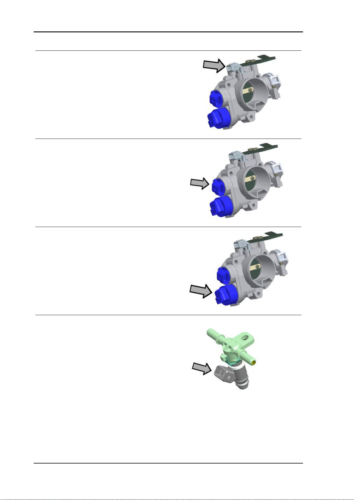
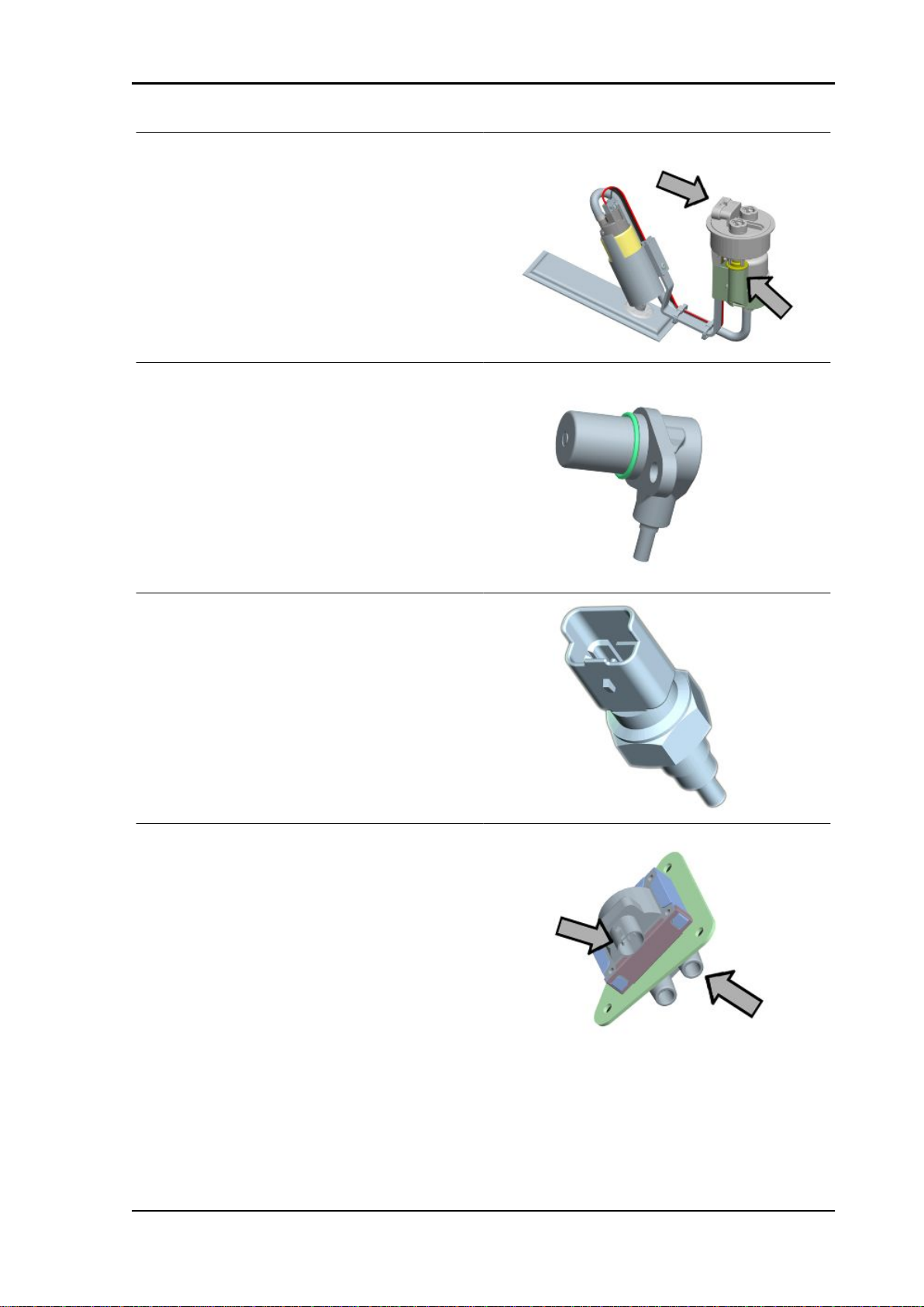
1. Air temperature sensor
2. Throttle valve sensor
ELE SYS - 19
Page 90

Electrical system GP 800 i.e.
3. Stepper motor
4. Rear cylinder fuel injector
5. Rpm timing sensor
6. Engine temperature sensor
7. To the front cylinder fuel injector
8. To the rear cylinder HV coil
9. Oil pressure sensor
10.To the voltage regulator
11.Starter motor cable
12.Rear cylinder fuel injector
13.To the front cylinder fuel injector
14.Speed sensor connector
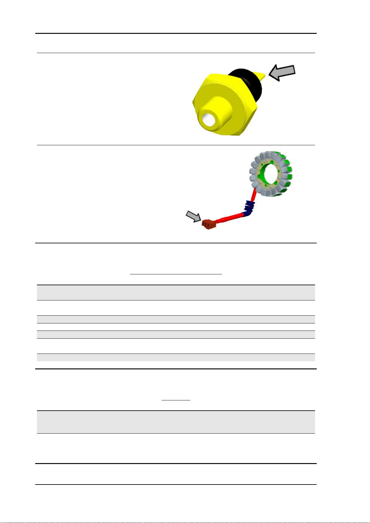
15.Lambda probe connector
16.Lambda probe
Conceptual diagrams
Ignition
KEY
1. Immobilizer decoder
ELE SYS - 20
Page 91

GP 800 i.e. Electrical system
2. Immobilizer aerial
14. Main fuses
15. Main relay
16. Key switch contacts
19. 1A diode
21. Auxiliary fuses
22. 12V - 14Ah battery
48. Instrument panel
51.Electronic ignition device (Engine connector)
52.Front cylinder HV coil
53. Rear cylinder HV coil
54. Electronic ignition device (Vehicle connector)
75. Injection load relay
Battery recharge and starting
KEY
3. Magneto flywheel
6. Resistance 120 Ohm - 2W
7. 1A diode
8. Stand button
ELE SYS - 21
Page 92

Electrical system GP 800 i.e.
9. 1A diode
10. Resistance 120 Ohm - 2W
11. Engine stop switch
12. 40A fuse
13. Voltage regulator
14. Main fuses
15. Main relay
16. Key switch contacts
17. Start-up remote control switch relay
18. Start-up maintenance relay
19. 1A diode
21. Auxiliary fuses
22. 12V - 14Ah battery
23. Starter motor
24. Start-up remote control switch
25. Starter button
26. Resistance 120 Ohm - 2W
27. 1A diode
28. 1A diode
35. Stop button on rear brake
36. Stop button on front brake
42. Rear light
A. Stop light LEDs
48. Instrument panel
54. Electronic ignition device (Vehicle connector)
ELE SYS - 22
Page 93

GP 800 i.e. Electrical system
Level indicators and enable signals section
KEY
14. Main fuses
15. Main relay
16. Key switch contacts
19. 1A diode
20. Key switch contacts
21. Auxiliary fuses
22. 12V - 14Ah battery
48. Instrument panel
49. Vehicle speed sensor
50. Barometric pressure sensor
51.Electronic ignition device (Engine connector)
54. Electronic ignition device (Vehicle connector)
55. Front cylinder fuel injector
56. Rear cylinder fuel injector
71. Fuel level transmitter
75. Injection load relay
77. Engine temperature sensor
ELE SYS - 23
Page 94

Electrical system GP 800 i.e.
78. Lambda probe
79. Throttle valve potentiometer
80. Air temperature sensor
81. Idle speed regulator
82. Engine rpm sensor
83. Monostable
84. External temperature sensor
85. Oil pressure sensor
Devices and accessories
KEY
4. Roll-over sensor
5. Diagnostics socket
14. Main fuses
15. Main relay
16. Key switch contacts
19. 1A diode
20. Key switch contacts
21. Auxiliary fuses
22. 12V - 14Ah battery
ELE SYS - 24
Page 95

GP 800 i.e. Electrical system
29. Saddle opening actuator
30.GPS wiring
31. LV coil - max.180W
32. Saddle opening receiver
33. Pre-installation for antitheft device
39. Helmet compartment light bulb
41. Rear left turn indicator bulb
43. Rear right turn indicator bulb
44. Front left turn indicator bulb
46. Front right turn indicator bulb
47. MODE button
48. Instrument panel
54. Electronic ignition device (Vehicle connector)
57. Electric fan relay
58. Electric fan
59. Wiring for accessories
60. Horn button
61. Horn
62. Helmet compartment light switch
63. Windshield DOWN button
64. Windshield UP button
65. Windshield limit switch
66. Windshield limit switch
70. Hand brake
72. Windshield motor
73. Windshield relay
74. Windshield relay
75. Injection load relay
76. Fuel pump
ELE SYS - 25
Page 96

Electrical system GP 800 i.e.
Lights and turn indicators
KEY
14. Main fuses
15. Main relay
16. Key switch contacts
19. 1A diode
20. Key switch contacts
21. Auxiliary fuses
22. 12V - 14Ah battery
34. Turn indicator switch
37. Turn indicator control device
38. Light switch
40. License plate bulb
41. Rear left turn indicator bulb
42. Rear light
B. Rear position light LEDs
43. Rear right turn indicator bulb
44. Front left turn indicator bulb
45. Headlight
ELE SYS - 26
Page 97

GP 800 i.e. Electrical system
A. Front position light bulb
B. Low-beam light bulb
C. High-beam light bulb
46. Front right turn indicator bulb
48. Instrument panel
54. Electronic ignition device (Vehicle connector)
67. Low-beam light relay
68. High-beam light relay
69. Resistance 120 Ohm - 2W
Checks and inspections
This section is devoted to the checks on the electrical system components.
Immobiliser
The EMS system is independent from the immobilizer antitheft device.
Its functions are:
- Start-up enabled by key recognition.
- Deterrent flashing.
The system consists of:
-EMS system control unit
- Decoder
- Aerial
- master key
- service key
- Deterrent and diagnosis LED
ELE SYS - 27
Page 98

Electrical system GP 800 i.e.
Virgin circuit
When control unit (ECU) and decoder are not programmed, the following conditions occur:
- Key switch set to «OFF»:
Deterrent flashing inactive.
- Key switch set to «ON»:
Ignition and injection disabled and LED on with
solid light.
When the key switch is set to "ON", the LED
switches on as shown in the figure.
The LED is turned on by the decoder.
Specific tooling
020460Y Scooter diagnosis and tester
To connect the diagnostic tester, open the battery
inspection port and pull out the EMS diagnosis
socket. Remove the protection cap and connect
the tester terminal.
Power the diagnostic tester by connecting the terminals to the battery poles, or the specific connector to the socket inside the helmet compartment.
ELE SYS - 28
Page 99

GP 800 i.e. Electrical system
Set the switch to "ON" and select the diagnostic
tester menu to the immobiliser function.
Scroll the pages to display the control unit data.
N.B.
AN UNPROGRAMMED SYSTEM CANNOT BE DETECTED UPON FIRST FITTING, OR IN CASE
THE DECODER AND THE CONTROL UNIT ARE REPLACED CONCURRENTLY.
The information will be as follows:
Unprogrammed control unit «ON»
Start-up disabled «ON»
Key number Zero › 250
1 Replacing the small cylinder
- Remove the original master key transponder and install it on the master key of the new cylinder.
- Program the system again as described in the injection chapter.
2 Decoder replacement
When the decoder is replaced it is necessary to program the system again.
Programming is indispensable for the engine start-up. (see injection chapter).
3 Control unit replacement
Programming is indispensable when the control unit is replaced to enable the engine start-up.
In this case it is sufficient to switch to "ON" using the master key.
N.B.
THE SERVICE KEY IS NOT USED FOR PROGRAMMING.
- WHEN NOT PROGRAMMED, THE CONTROL UNIT ALLOWS NO FUNCTIONAL DIAGNOSIS ON
THE ENGINE.
4 Replacing or duplicating service keys
Keys can be duplicated using the blank keys and the original master key.
WITH MASTER KEY
When the key switch is set to "ON" and programming is performed normally, the LED switches on
as shown in the figure.
After the confirmation flash when switching to
"ON", a number of flashes are emitted, equal to the
number of keys used for programming.
ELE SYS - 29
Page 100

Electrical system GP 800 i.e.
WITH SERVICE KEYS
After the confirmation flash when switching to
«ON», the LED remains off.
Switching from «ON» to «OFF» with programmed
system causes the intermittent switching on of the
LED, with an antitheft effect.
This occurs with any key used for programming.
If the scooter is not used, the deterrent light stops automatically after 48 hours to prevent discharging
the battery. A new 48-h cycle starts by switching from "OFF" to "ON" and "OFF" again.
Diagnostic codes
The LED indication is divided into 3 steps:
1st step: A flash: "ON" switching recognition
2nd step: Series of flashes: diagnosis code indication
3rd step: Steady light on or off:
on = start-up disabled off = start-up enabled
Diagnostic code - 1 flash
Code 1 indicates a non-programmed system.
If the code is still displayed after having carried out
the programming procedure, repeat the procedure
carefully observing the "ON" times of each key.
If the code is still displayed, proceed as follows:
- Disconnect the battery negative.
- Remove the control unit connector.
- Remove the main decoder connector.
N.B.
ELE SYS - 30
 Loading...