

Page 1

N72
Multicell System
Installation, configuration and operation
0 DECT IP
Page 2

2
Page 3

Gigaset N720 DECT IP Multicell System ...
Gigaset N720 DECT IP Multicell System ...
... the DECT IP multicell system for Internet telephony and unrestricted mobility when
making calls in small and medium-sized companies.
Enable Internet telephony for up to 100 subscribers
Enable your company's employees to make calls via the Internet and, at the same time,
benefit from DECT telephony:
Available throughout the DECT network, freedom of movement when making calls.
Manage the phone functions centrally at a management station
Manage your Gigaset telephone system via your PC's Web browser. Save your
telephone system's configuration on your PC after you have set it up.
Organise and synchronise your base stations
Register the base stations belonging to your DECT network and define a
synchronisation hierarchy. If your base stations are a long way apart, create
independent DECT clusters and manage them from a central point.
Manage handsets
Register the handsets on the DECT network. Configure VoIP connections and set up
network and individual mailboxes for your company's employees.
Make important functions available centrally
Make public and corporate directories available to employees.
Go online with your Gigaset
Use your phone's Info Centre and have information specifically provided for the phone
from the Internet shown on the display of the registered handsets.
Practical functions
Use the programmable display keys on the registered handsets to quickly access
important phone functions, or read your eMail messages on your phone (without a PC).
You can find additional information about your phone at
www.gigaset.com/pro/gigasetn720
Have fun using your new telephone system!
3
Page 4

Tab le of Cont ents
Table of Contents
Gigaset N720 DECT IP Multicell System ... . . . . . . . . . . . . . . . . . . . . . . . . . . . 3
Introduction . . . . . . . . . . . . . . . . . . . . . . . . . . . . . . . . . . . . . . . . . . . . . . . . . . . . . . 6
Safety precautions . . . . . . . . . . . . . . . . . . . . . . . . . . . . . . . . . . . . . . . . . . . . . . . . . 9
First steps . . . . . . . . . . . . . . . . . . . . . . . . . . . . . . . . . . . . . . . . . . . . . . . . . . . . . . . . 10
Checking the package contents . . . . . . . . . . . . . . . . . . . . . . . . . . . . . . . . . . . . . . . . . . . . . . 10
Installing base stations and DECT Manager – procedure . . . . . . . . . . . . . . . . . . . . . . . 11
Connecting base stations and DECT Manager . . . . . . . . . . . . . . . . . . . . . . . . . . . . . . . . . 12
Connecting devices to the local network and to the Internet . . . . . . . . . . . . . . . . . . 14
Mounting devices on the wall . . . . . . . . . . . . . . . . . . . . . . . . . . . . . . . . . . . . . . . . . . . . . . . . 16
Preparing to use the telephone system . . . . . . . . . . . . . . . . . . . . . . . . . . . . . . . . . . . . . . . 17
How to proceed . . . . . . . . . . . . . . . . . . . . . . . . . . . . . . . . . . . . . . . . . . . . . . . . . . . . . . . . . . . . . 21
Operating information . . . . . . . . . . . . . . . . . . . . . . . . . . . . . . . . . . . . . . . . . . . . 22
Light emitting diodes (LED) . . . . . . . . . . . . . . . . . . . . . . . . . . . . . . . . . . . . . . . . . . . . . . . . . . 22
Resetting the device settings . . . . . . . . . . . . . . . . . . . . . . . . . . . . . . . . . . . . . . . . . . . . . . . . . 24
Menu tree (handsets) . . . . . . . . . . . . . . . . . . . . . . . . . . . . . . . . . . . . . . . . . . . . . . . . . . . . . . . . 26
Understanding the operating steps . . . . . . . . . . . . . . . . . . . . . . . . . . . . . . . . . . . . . . . . . . . 27
Making calls . . . . . . . . . . . . . . . . . . . . . . . . . . . . . . . . . . . . . . . . . . . . . . . . . . . . . . 29
Calling . . . . . . . . . . . . . . . . . . . . . . . . . . . . . . . . . . . . . . . . . . . . . . . . . . . . . . . . . . . . . . . . . . . . . . . 29
Ending a call . . . . . . . . . . . . . . . . . . . . . . . . . . . . . . . . . . . . . . . . . . . . . . . . . . . . . . . . . . . . . . . . . 30
Accepting a call . . . . . . . . . . . . . . . . . . . . . . . . . . . . . . . . . . . . . . . . . . . . . . . . . . . . . . . . . . . . . . 31
Calling Line Identification . . . . . . . . . . . . . . . . . . . . . . . . . . . . . . . . . . . . . . . . . . . . . . . . . . . . 31
Call waiting during a call . . . . . . . . . . . . . . . . . . . . . . . . . . . . . . . . . . . . . . . . . . . . . . . . . . . . . 33
Initiating ringback . . . . . . . . . . . . . . . . . . . . . . . . . . . . . . . . . . . . . . . . . . . . . . . . . . . . . . . . . . . 33
Initiating a consultation call . . . . . . . . . . . . . . . . . . . . . . . . . . . . . . . . . . . . . . . . . . . . . . . . . . 34
Call swapping . . . . . . . . . . . . . . . . . . . . . . . . . . . . . . . . . . . . . . . . . . . . . . . . . . . . . . . . . . . . . . . 34
Transferring a call to another subscriber . . . . . . . . . . . . . . . . . . . . . . . . . . . . . . . . . . . . . . 35
"Anonymous calling" . . . . . . . . . . . . . . . . . . . . . . . . . . . . . . . . . . . . . . . . . . . . . . . . . . . . . . . . . 35
Gigaset HDSP – telephony with brilliant sound quality . . . . . . . . . . . . . . . . . . . . . . . . 36
Setting phone functions . . . . . . . . . . . . . . . . . . . . . . . . . . . . . . . . . . . . . . . . . . 37
Activating/deactivating call waiting for calls . . . . . . . . . . . . . . . . . . . . . . . . . . . . . . . . . . 37
Using call forwarding (CF) . . . . . . . . . . . . . . . . . . . . . . . . . . . . . . . . . . . . . . . . . . . . . . . . . . . . 37
Do not disturb . . . . . . . . . . . . . . . . . . . . . . . . . . . . . . . . . . . . . . . . . . . . . . . . . . . . . . . . . . . . . . . 38
Using directories . . . . . . . . . . . . . . . . . . . . . . . . . . . . . . . . . . . . . . . . . . . . . . . . . 39
Using corporate directories . . . . . . . . . . . . . . . . . . . . . . . . . . . . . . . . . . . . . . . . . . . . . . . . . . 40
Using online directories . . . . . . . . . . . . . . . . . . . . . . . . . . . . . . . . . . . . . . . . . . . . . . . . . . . . . . 41
Using the call lists . . . . . . . . . . . . . . . . . . . . . . . . . . . . . . . . . . . . . . . . . . . . . . . . 44
Viewing entries . . . . . . . . . . . . . . . . . . . . . . . . . . . . . . . . . . . . . . . . . . . . . . . . . . . . . . . . . . . . . . 44
Dialling a number from a list . . . . . . . . . . . . . . . . . . . . . . . . . . . . . . . . . . . . . . . . . . . . . . . . . 45
Copying an entry from the call list to the local directory. . . . . . . . . . . . . . . . . . . . . . . . 45
Deleting an entry/list . . . . . . . . . . . . . . . . . . . . . . . . . . . . . . . . . . . . . . . . . . . . . . . . . . . . . . . . 45
4
Page 5

Tab le of Cont ents
Displaying messages . . . . . . . . . . . . . . . . . . . . . . . . . . . . . . . . . . . . . . . . . . . . . 46
Using the network mailbox . . . . . . . . . . . . . . . . . . . . . . . . . . . . . . . . . . . . . . . . . . . . . . . . . . . 46
eMail notifications . . . . . . . . . . . . . . . . . . . . . . . . . . . . . . . . . . . . . . . . . . . . . . . . . . . . . . . . . . . 48
Info centre – continuous Internet access from your phone . . . . . . . . . . 52
Starting the info centre, selecting info services . . . . . . . . . . . . . . . . . . . . . . . . . . . . . . . . 52
Login for personalised info services . . . . . . . . . . . . . . . . . . . . . . . . . . . . . . . . . . . . . . . . . . . 53
Operating the info centre . . . . . . . . . . . . . . . . . . . . . . . . . . . . . . . . . . . . . . . . . . . . . . . . . . . . 54
System settings and settings on the handset . . . . . . . . . . . . . . . . . . . . . . . 56
Date and time . . . . . . . . . . . . . . . . . . . . . . . . . . . . . . . . . . . . . . . . . . . . . . . . . . . . . . . . . . . . . . . 56
Quickly accessing functions . . . . . . . . . . . . . . . . . . . . . . . . . . . . . . . . . . . . . . . . . . . . . . . . . . 56
Configuring the system on the DECT Manager . . . . . . . . . . . . . . . . . . . . . 58
Using the Web configurator . . . . . . . . . . . . . . . . . . . . . . . . . . . . . . . . . . . . . . . . . . . . . . . . . . 58
Web configurator menu . . . . . . . . . . . . . . . . . . . . . . . . . . . . . . . . . . . . . . . . . . . . . . . . . . . . . . 63
Connecting the DECT Manager to the local network (LAN/router) . . . . . . . . . . . . . 64
Configuring and synchronising base stations . . . . . . . . . . . . . . . . . . . . . . . . . . . . . . . . . 67
Security settings . . . . . . . . . . . . . . . . . . . . . . . . . . . . . . . . . . . . . . . . . . . . . . . . . . . . . . . . . . . . . 71
Configuring VoIP providers . . . . . . . . . . . . . . . . . . . . . . . . . . . . . . . . . . . . . . . . . . . . . . . . . . . 73
Configuring handsets . . . . . . . . . . . . . . . . . . . . . . . . . . . . . . . . . . . . . . . . . . . . . . . . . . . . . . . . 75
Additional settings for making a call . . . . . . . . . . . . . . . . . . . . . . . . . . . . . . . . . . . . . . . . . . 82
Info services . . . . . . . . . . . . . . . . . . . . . . . . . . . . . . . . . . . . . . . . . . . . . . . . . . . . . . . . . . . . . . . . . 88
Online directories . . . . . . . . . . . . . . . . . . . . . . . . . . . . . . . . . . . . . . . . . . . . . . . . . . . . . . . . . . . . 89
Device management . . . . . . . . . . . . . . . . . . . . . . . . . . . . . . . . . . . . . . . . . . . . . . . . . . . . . . . . . 92
DECT Manager and base station status . . . . . . . . . . . . . . . . . . . . . . . . . . . . . . . . . . . . . . . 98
Customer care . . . . . . . . . . . . . . . . . . . . . . . . . . . . . . . . . . . . . . . . . . . . . . . . . . . . 99
Questions and answers . . . . . . . . . . . . . . . . . . . . . . . . . . . . . . . . . . . . . . . . . . . . . . . . . . . . . . 99
Information on operating Gigaset VoIP telephones with routers with
Network Address Translation (NAT) . . . . . . . . . . . . . . . . . . . . . . . . . . . . . . . . . . . . . . . . . . 101
Checking service information . . . . . . . . . . . . . . . . . . . . . . . . . . . . . . . . . . . . . . . . . . . . . . . 103
Environment . . . . . . . . . . . . . . . . . . . . . . . . . . . . . . . . . . . . . . . . . . . . . . . . . . . 104
Our environmental mission statement . . . . . . . . . . . . . . . . . . . . . . . . . . . . . . . . . . . . . . . 104
Environmental management system . . . . . . . . . . . . . . . . . . . . . . . . . . . . . . . . . . . . . . . . 104
Disposal . . . . . . . . . . . . . . . . . . . . . . . . . . . . . . . . . . . . . . . . . . . . . . . . . . . . . . . . . . . . . . . . . . . . 104
Appendix . . . . . . . . . . . . . . . . . . . . . . . . . . . . . . . . . . . . . . . . . . . . . . . . . . . . . . 105
Care . . . . . . . . . . . . . . . . . . . . . . . . . . . . . . . . . . . . . . . . . . . . . . . . . . . . . . . . . . . . . . . . . . . . . . . . 105
Contact with liquid . . . . . . . . . . . . . . . . . . . . . . . . . . . . . . . . . . . . . . . . . . . . . . . . . . . . . . . . 105
Authorisation Gigaset N720 IP PRO . . . . . . . . . . . . . . . . . . . . . . . . . . . . . . . . . . . . . . . . . . 105
Authorisation Gigaset N720 DM PRO . . . . . . . . . . . . . . . . . . . . . . . . . . . . . . . . . . . . . . . . 105
Specifications . . . . . . . . . . . . . . . . . . . . . . . . . . . . . . . . . . . . . . . . . . . . . . . . . . . . . . . . . . . . . . . 106
Glossary . . . . . . . . . . . . . . . . . . . . . . . . . . . . . . . . . . . . . . . . . . . . . . . . . . . . . . . 107
Accessories . . . . . . . . . . . . . . . . . . . . . . . . . . . . . . . . . . . . . . . . . . . . . . . . . . . . . 120
Index . . . . . . . . . . . . . . . . . . . . . . . . . . . . . . . . . . . . . . . . . . . . . . . . . . . . . . . . . . 124
5
Page 6
Introduction
Introduction
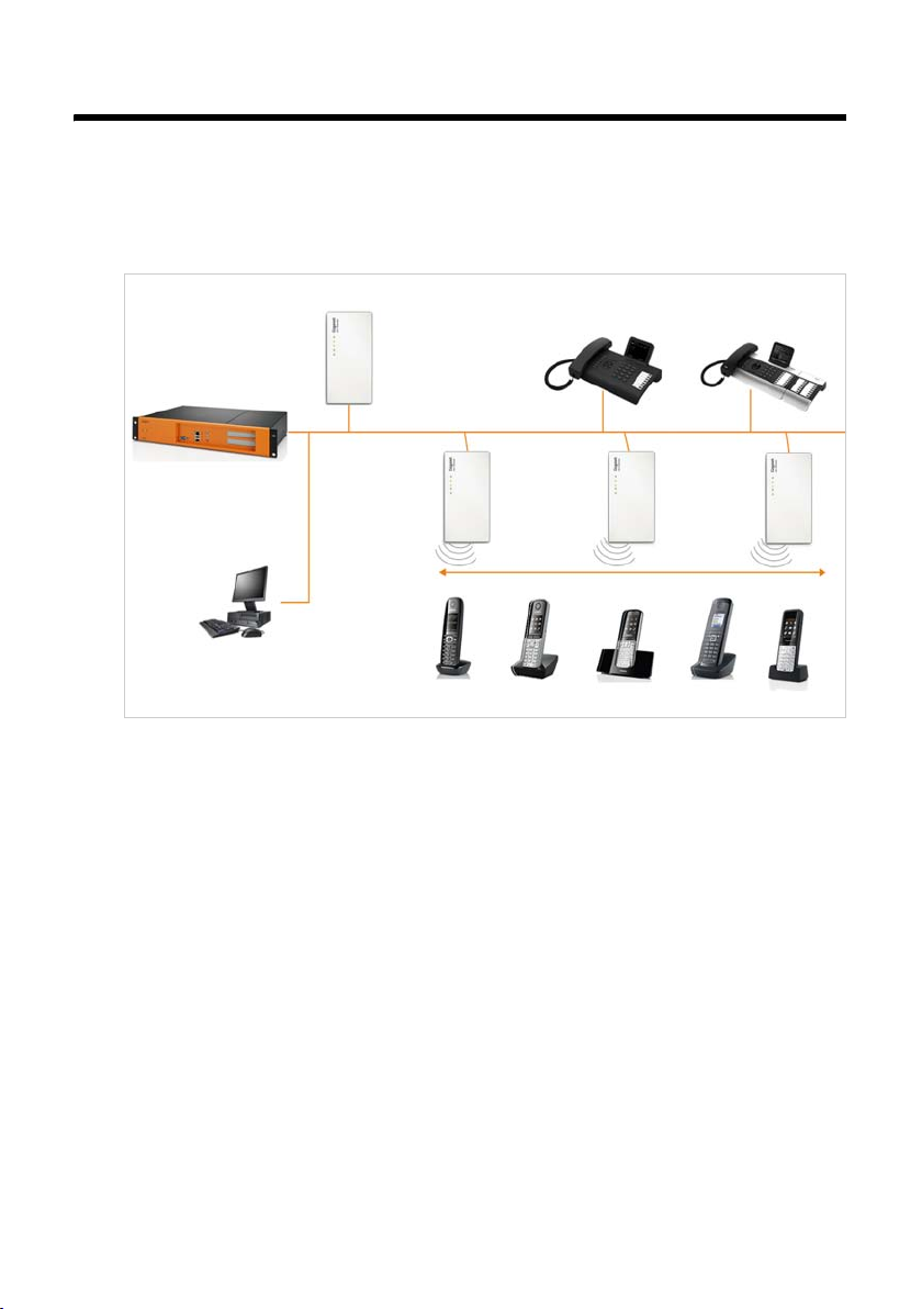
Gigaset N720 DECT IP Multicell System is a DECT multicell system for connecting DECT
base stations to a VoIP PABX. It combines the options of IP telephony with the use of DECT
telephones.
The following illustration shows the components of the Gigaset N720 DECT IP Multicell
System and the way the system is embedded in the IP telephone environment:
Gigaset IP PRO telephones
DECT Manager
Gigaset N720 DM PRO
e.g., Gigaset DE 900 IP PRO
LAN
PAB X
VoIP, ISDN, analogue
Configuration via
Web interface
u DECT Manager Gigaset N720 DM PRO
Central management station for managing the DECT network. One DECT Manager
must be used for each installation. The DECT Manager
– Manages up to 20 DECT base stations
– Manages up to 100 handsets on multicell systems
– Enables division into subnets (Cluster formation)
– Represents the interface to an IP PABX (e.g., Gigaset T500 PRO/T300 PRO)
The DECT Manager offers a Web user interface for the configuration and
administration of the DECT network.
Getting started with the DECT Manager
Configuring the DECT network using the Web user interface
u Gigaset N720 IP PRO DECT base stations
– These are the cells of the DECT telephone network.
– Each base station can manage up to eight calls simultaneously.
Getting started with the base stations
Configuring the base stations
DECT
base stations
Gigaset N720
IP PRO
Handover & roaming
Gigaset
Handsets
£ page 11
£ page 58
£ page 11
£ page 67
6
Page 7

Introduction
u Gigaset handsets
– Up to 100 handsets can be connected and 30 DECT connections can be made
simultaneously (calls, eMail checks, connections to online directories and the Info
Centre).
The following handsets are recommended: Gigaset SL610H PRO, SL400H, S810H,
E49H.
Further information relating to the functions of the handsets in connection with
the Gigaset base stations can be found in the Accessories section (
and on the Service page at www.gigaset.com/pro/gigasetn720
– Subscribers can accept or initiate calls in all DECT cells with their handset
(Roaming), and can also switch between the DECT cells during a call (Handover).
A handover is only possible within the same cluster.
Configuring handsets
The functions of a handset on a Gigaset N720 DECT IP Multicell System are described
in this document using the example of the Gigaset SL610H PRO handset. Detailed
information about this handset and other approved Gigaset handsets can be found in
the relevant user guide. These are provided on the product CD or on the Internet at
www.gigaset.com
u PAB X
You can connect your DECT telephone system to a PABX for VoIP, ISDN or analogue
telephony, e.g.,
– A Gigaset T500 PRO or T300 PRO
– A PABX from another manufacturer
– A PABX over the Internet (hosted PBX)
The PABX
– Establishes the connection to a public telephone network
– Enables central management of telephone connections, directories, network
mailboxes
u Forming clusters with the Gigaset N720 DECT IP Multicell System
You can divide DECT base stations that you have installed at your location into several
independent groups, i.e., clusters, and manage them using one Gigaset N720 DM PRO
DECT Manager (
This means DECT domains that are a long way apart can be managed from a central
point. The DECT Manager is connected to the base stations and the PABX via the local
network and is therefore not dependent on DECT ranges. It guarantees access to the
centrally configured IP connections, directories etc. However, a handover of handsets
between clusters is not possible.
£ page 75
.
£ page 70).
£ page 123)
on the Internet.
7
Page 8

Introduction
Planning your DECT wireless network
Careful planning of your DECT wireless network is the prerequisite for successful
operation of the Gigaset N720 DECT IP Multicell System with good call quality and
adequate call options for all subscribers in all the buildings and areas belonging to the
PABX. When deciding how many base stations are needed, and where these should be
positioned, both the requirements for the capacity of the PABX and its wireless coverage,
as well as many ambient conditions, must be taken into consideration.
The "Gigaset N720 DECT IP Multicell System - Site Planning and Measurement Guide"
provided on the enclosed product CD will make it easier for you to plan your multicell
DECT network, explain the necessary preparatory work for the installation and describe
how to carry out measurements in order to find the best positions for your base stations.
Please read these instructions before starting installation.
Gigaset also offers the Gigaset N720 SPK PRO (Site Planning Kit) to help you measure the
wireless coverage and signal quality on your DECT network. Information about setting up
and using the Gigaset measuring equipment can also be found in the "Gigaset N720 DECT
IP Multicell System - Site Planning and Measurement Guide".
8
Page 9
Safety precautions
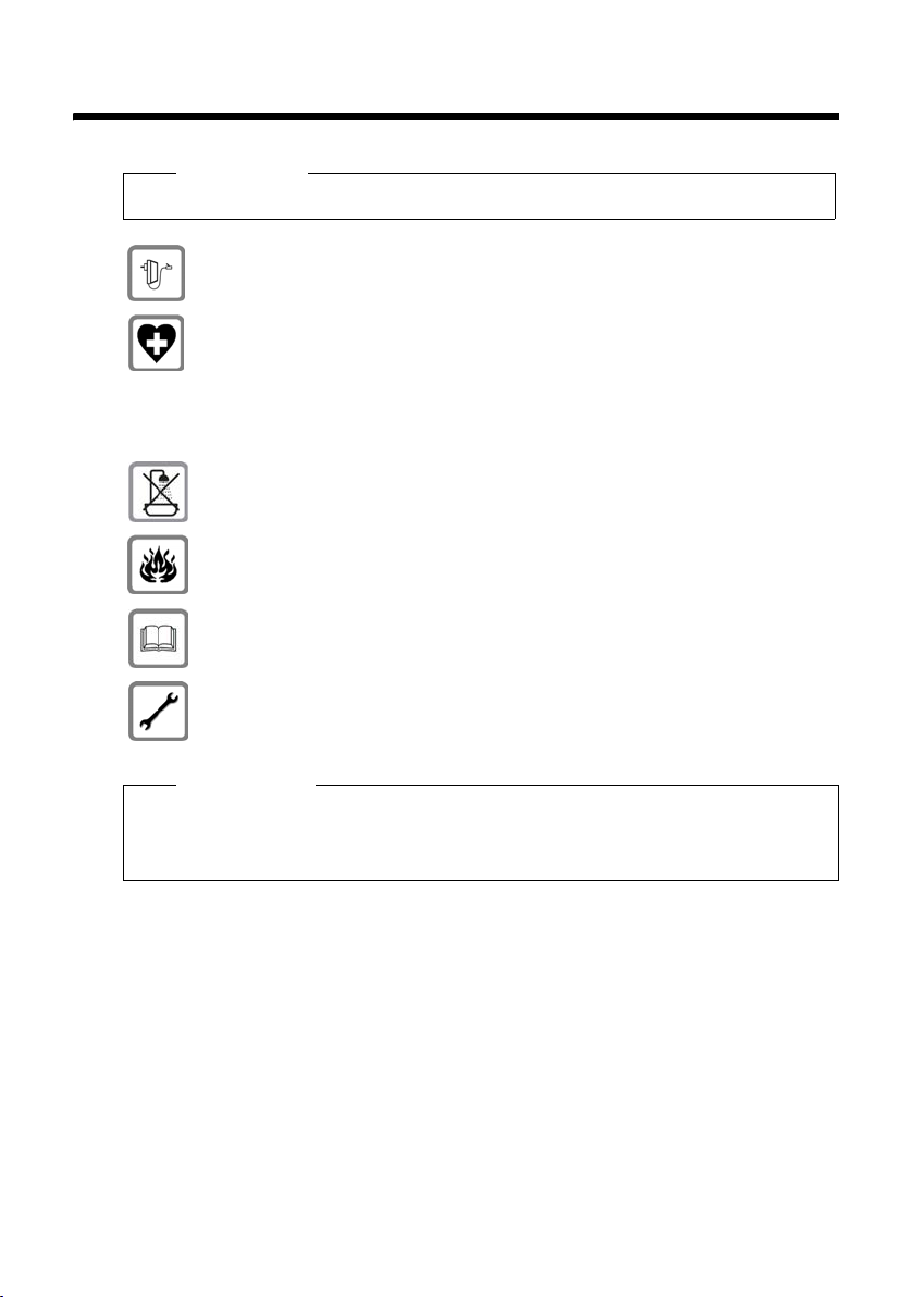
Warning
Read the safety precautions and the user guide before use.
Use only the power adapter supplied, as indicated on the devices.
Using your telephone may affect nearby medical equipment. Be aware of the
technical conditions in your specific location e.g., doctor's surgery.
If you use a medical device (e.g., a pacemaker), please contact the device
manufacturer. They will be able to advise you regarding the susceptibility of
the device to external sources of high frequency energy. Please refer to the
Appendix chapter for the specifications of this Gigaset product.
The devices are not splashproof. For this reason do not install them in a damp
environment such as bathrooms or shower rooms.
Do not use the devices in environments with a potential explosion hazard
(e.g., paint shops).
If you give your Gigaset to a third party, make sure you also give them the user
guide.
Safety precautions
Remove faulty devices from use or have them repaired by our Service team, as
these could interfere with other wireless services.
Please note
u Not all of the functions described in this user guide are available in all countries.
u The devices cannot be used in the event of a power failure. It is also not possible to
transmit emergency calls.
9
Page 10
First steps
First steps
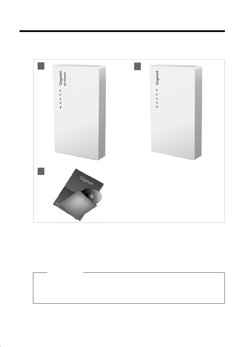
Checking the package contents
1
3
§§1§§ One Gigaset N720 DM PRO DECT Manager or
§§2§§ One Gigaset N720 IP PRO base station
§§3§§ One CD with user guide (Gigaset N720 DM PRO only)
This includes, for example, the "Gigaset N720 DECT IP Multicell System - Site Planning
and Measurement Guide", £ page 8
Or
2
Please note
The Gigaset N720 DECT IP Multicell System devices are powered by Power over
Ethernet (PoE). If you do not use an Ethernet switch with PoE functionality and require
a power adapter to connect to the mains power supply, you can order this as an
accessory (
10
£ page 120).
Page 11

Firmware updates
Whenever there are new or improved functions for your Gigaset, firmware updates are
made available for you to download to your DECT Manager and your base station
£ page 97). If this results in operational changes when using your phone, a new
(
version of this user guide or the necessary amendments will be published on the
Internet at
www.gigaset.com/pro
Select the product to open the relevant product page for your base, where you will
find a link to the user guides.
To find out which version of the DECT Manager firmware is currently loaded,
£ page 97 and page 103.
see
Installing base stations and DECT Manager – procedure
Caution
Read the "Gigaset N720 DECT IP Multicell System - Site Planning and Measurement
Guide" before you start installing the devices.
¤ When installing the base stations, please take into account the technical conditions for
positioning and the installation guidelines, which are described in the "Gigaset N720
DECT IP Multicell System -Site Planning and Measurement Guide".
¤ Install the base stations at the positions you determined when planning or measuring
your DECT wireless network.
¤ The Gigaset N720 DM PRO (DECT Manager) can be installed anywhere within the
range of the local network. It does not need to be installed in the coverage area of the
DECT wireless network.
¤ The Gigaset N720 IP PRO base stations and the Gigaset N720 DM PRO DECT Manager
are intended for wall mounting (
£ page 16).
First steps
Caution
u The devices are designed for use in dry rooms with a temperature range of +5°C to
+45°C.
u Never expose the devices to heat sources, direct sunlight or other electrical
appliances.
u Protect your Gigaset from moisture, dust, corrosive liquids and fumes.
11
Page 12

First steps
Connecting base stations and DECT Manager
To be able to make calls with your Gigaset N720 DECT IP Multicell System via VoIP, the
following conditions must be fulfilled:
u The DECT Manager is installed
u Your DECT Manager and base station are connected to the local network (£ page 14)
u At least one base station is registered (£ page 17)
u At least one handset is registered to the telephone system (£ page 18)
Perform the following steps in the specified sequence, first for the DECT Manager and
then for all the base stations to be installed:
§§1§§ Connect the power cable to the device and connect to the mains power supply, if
necessary.
§§2§§ Connect the base to the router/switch to access the local network and configure via
the Web configurator.
§§3§§ Fix the device to the planned position on the wall.
Please note
Your Gigaset N720 DECT IP Multicell System is supplied with sufficient power via PoE
(Power over Ethernet) if the device is connected to an Ethernet switch with PoE
functionality (PoE class IEEE802.3af). In this case, you do not need to connect the
device to the mains power supply and step
§§1§§ can be omitted.
12
Page 13
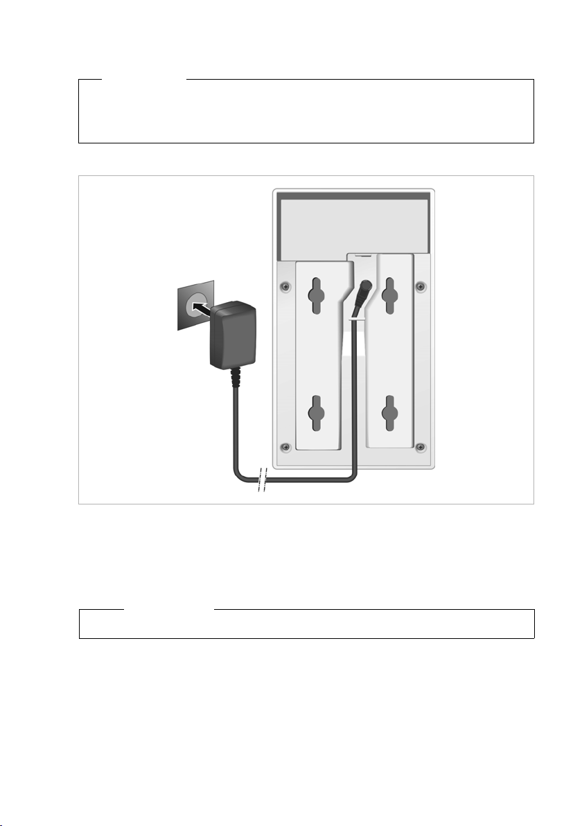
Connecting the power cable
Please note
This connection is only required if the device is not powered via PoE.
If you do not use PoE, the power adapter must be plugged in at all times for
operation, as the device will not work without a power supply.
First steps
§§1§§ Insert the power cable of the power adapter into the connection socket at the rear of
the device.
§§2§§ Insert the cable into the cable recess provided.
§§3§§ Insert the power adapter into the mains socket.
Caution
Use only the power adapter recommended in the Accessories section (£ page 120).
13
Page 14

First steps
Connecting devices to the local network and to the Internet
Data protection notice
When the device is connected to the Internet, it automatically contacts the Gigaset
support server to make it easier for you to configure the devices and to enable
communication with Internet services.
For this purpose, the DECT Manager sends the following information when the system
is started and then every five hours:
u Serial number/item number
u MAC address
u IP address for the Gigaset on the LAN/its port numbers
u Device name
u Software version
The following data is transmitted once every day.
u Number of registered handsets
u Information for each handset: DECT identifier (IPUI), device type, user name and
display name
On the support server, this information is linked to the existing device-specific
information:
u System-related/device-specific passwords
The base stations and DECT Manager have a LAN connection, which you use to connect
the device to your local network via a switch/hub or directly with a router. A VoIP PABX is
required for Internet telephony. This must be accessible via the local network and must
have network access (to the Internet and/or the analogue or ISDN telephone network).
Otherwise it will only be possible to make calls within the LAN.
You also need a PC connected to the local network, so that you can configure your
telephone system via the Web configurator.
Caution
Each base station contains two DECT modules with their own MAC address, which are
connected to a LAN port via an integral Ethernet switch.
To prevent security warnings, you will need to allow MAC address cascading on your
corporate network.
14
Page 15
First steps
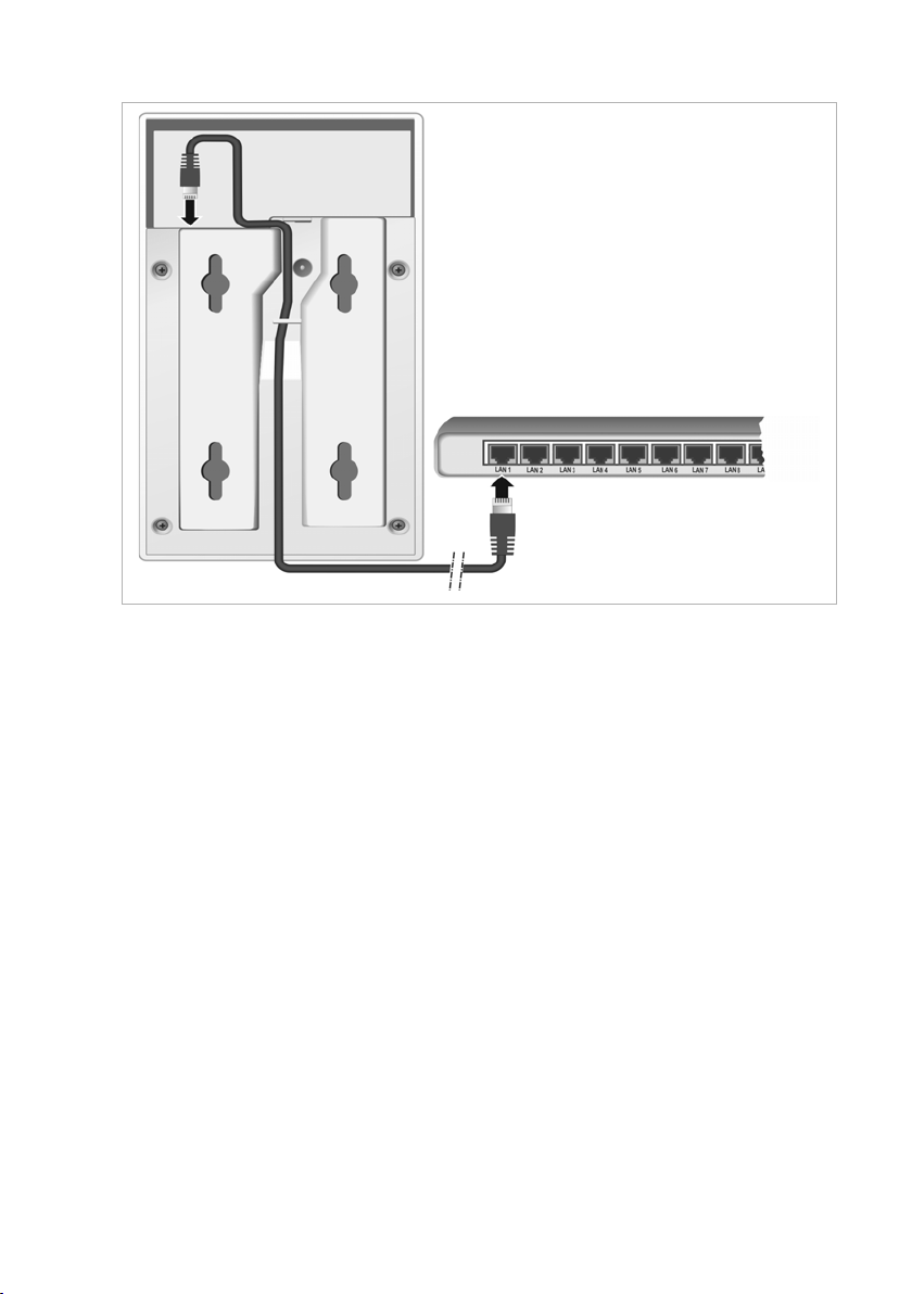
§§1§§ Insert a plug from the Ethernet cable supplied (Cat 5 with 2 RJ45 modular jacks) into
the LAN connection socket at the rear of the device.
§§2§§ Insert the second Ethernet cable plug into a LAN socket for your local network or on
the router.
§§3§§ Insert the cable into the cable recess provided.
15
Page 16
First steps
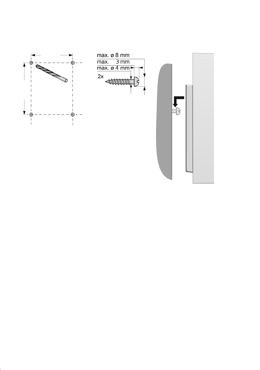
Mounting devices on the wall
Gigaset N720 IP PRO base stations and Gigaset N720 DM PRO DECT Manager are intended
for wall mounting.
50 mm
80 mm
You can fix the device to the wall with two or four
screws:
¤ Drill holes with the following spacing:
Horizontal: 50 mm, vertical: 80 mm.
¤ Affix wall plugs and secure the screws. Let the
screws protrude by approx. four mm.
¤ Hang the device on the screws.
16
Page 17

Preparing to use the telephone system
To start using your Gigaset N720 DECT IP Multicell System, you must now perform the
following steps:
u Register base stations to the telephone system and synchronise them
u Register handsets to the telephone system, configure and assign VoIP accounts
Registering base stations to the DECT Manager
Before starting to register the base stations, please ensure that you have the installation
plans available, which you created during the planning phase of your DECT network.
You need the MAC address of the installed base stations and the following planning data:
u Name, location
You can select any name for the base station. This should contain its location, to enable
the relevant Gigaset N720 IP PRO to be found quickly for maintenance purposes.
u Synchronisation level
Base stations that combine to form a DECT wireless network must synchronise with
one another to ensure a smooth transition of the handsets from cell to cell (handover).
As a base station in a multicell DECT network often has an inadequate connection to
some of the other base stations, you must set up a synchronisation hierarchy.
Detailed information about synchronisation planning can be found in "Gigaset N720
DECT IP Multicell System - Site Planning and Measurement Guide".
u Cluster structure
Groups of base stations that are a long way apart must be assigned to different
clusters.
First steps
Please note
Synchronisation always refers to a cluster. You can set up several clusters that are not
synchronised with one another, so there is no possibility of a handover between
clusters.
To register the base stations, set up clusters and define the synchronisation hierarchy,
please use the Web configurator on the DECT Manager. This is described in Section
Configuring the system on the DECT Manager (
£ page 58).
17
Page 18

First steps
Registering base stations
¤ Open the Web configurator and log in (£ page 59).
¤ Open the Preferences ¢ Network and connectors ¢ Base station registration
£ page 67).
page (
The window shows a list of all DECT base stations connected to the local network
which have not yet been registered. The base stations are identified by their MAC
address and by the date and time of their initial contact with the system.
¤ Register all the base stations that are to belong to your telephone system, as described
in section "Registering base stations".
Synchronising base stations and forming clusters
¤ Open the Preferences ¢ Network and connectors ¢ Base station synchronisation
£ page 70).
page (
The registered base stations are displayed.
¤ Assign each base station to a cluster.
If you only want to manage one cluster, assign all the base stations to the same cluster
number.
¤ Assign the planned synchronisation level to each base station.
Be aware that synchronisation level one can only be assigned once.
¤ Save your settings.
Synchronisation starts automatically. If synchronisation is successful, this is indicated by
the DECT 1 / DECT 2 LEDs on the Gigaset N720 IP PRO base stations (
£ page 23).
Registering handsets and assigning VoIP accounts
All the handsets to be used for making calls on the Gigaset N720 DECT IP Multicell System
must be registered on the DECT Manager. When registering, the handset is permanently
assigned a VoIP connection as the receive and send connection.
Up to 100 handsets can be connected.
The following handsets are recommended: Gigaset SL610H PRO, SL400H, S810H, E49H.
Further information relating to the functions of the handsets in connection with the
Gigaset base stations can be found in the Accessories section (
Service page at www.gigaset.com/pro/gigasetn720
18
on the Internet.
£ page 123) and on the
Page 19

First steps
Setting up VoIP connections
Before you start registering the handsets, please make sure that there are sufficient
accounts available from your local VoIP PABX or from a VoIP provider, and that you have the
login data to hand. You can set up accounts from a maximum of ten different providers.
First configure the VoIP connections.
¤ Log in to the Web configurator (£ page 59).
¤ Open the Settings ¢ VoIP providers page and create an entry for each provider
£ page 73).
(
Registering the handset
Handset registration must be initiated in parallel on the DECT Manager (a) and on the
handset (b). To do so, the handset must be located in at least one cell of the DECT
network, i.e., close to a base station which is registered on the DECT Manager.
a) On the DECT Manager
¤ Open the Web configurator and log in (£ page 59).
¤ Open the Settings ¢ Handsets (£ page 75) page and press the Add button. You can
decide whether you want to set up a handset with new data, or transfer the data from
a handset that has already been set up.
¤ Select the VoIP provider from the list and enter the login data for the account the
handset is to use to make calls.
¤ Start registering the handset for this account.
The DECT Manager is now ready for registering. A registration PIN is generated and
displayed.
b) On the handset
¤ Start the registration procedure on the handset in accordance with the handset's user
guide.
A message appears on the display stating that the handset is searching for a base that is
ready for registration.
If the handset has found a base, you will be asked to enter the registration PIN.
¤ Enter the four-digit registration PIN, produced on the DECT Manager, on the handset.
c) On the DECT Manager
¤ Confirm the message Registration successful. by clicking OK.
Once registration is complete, the handset returns to idle status. The handset name is
shown in the display. If not, repeat the procedure.
Please note
The handset name is either the Username or Display name for the VoIP account to
which the handset is assigned. You can set this in the Web configurator (
Immediately after registration, the handset is assigned the VoIP connection as the receive
and send connection (incoming calls are signalled on the handset and can be answered).
You can now make calls with the handset.
£ page 75).
19
Page 20

First steps
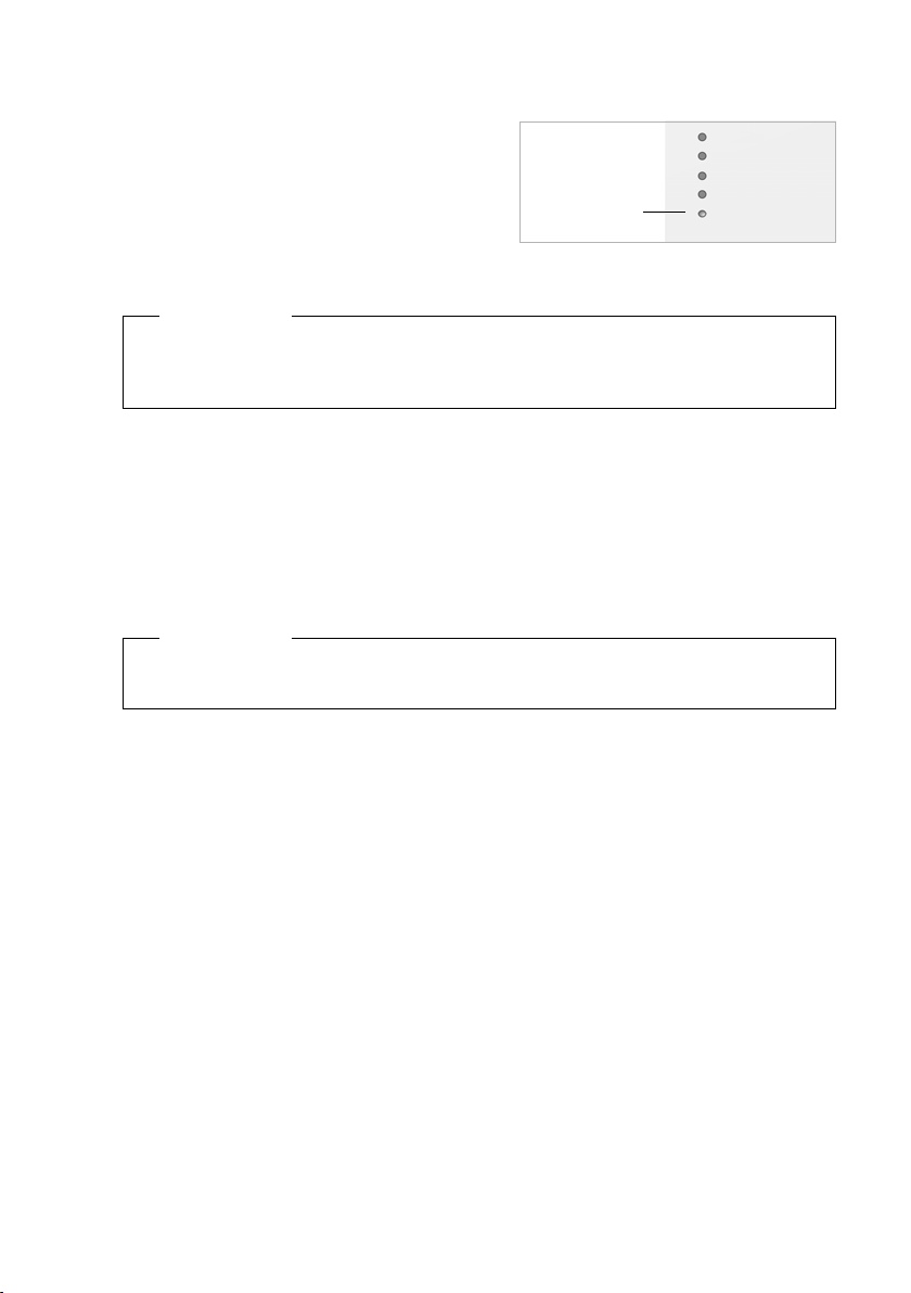
Displays
u Reception between the base station and the handset:
– Good to poor:
–No reception: ¼ (red)
If several base stations are within range, the connection
quality to the base station with the best reception is
displayed.
u Battery charge status:
–
yy{{ (Empty to full)
yFlashes red: batteries almost empty
–
xyx{x{ (Charging)
–
u Name of the handset
ÐiÑÒ
i
07:15
Name 14 Oct
Calls Calendar
Please note
Depending on the device type, you can register your handset on other individual base
stations or on a Gigaset N720 DECT IP Multicell System (up to four). Information about
this can be found in the user guides for the relevant handsets and base stations.
V
20
Page 21

How to proceed
Now you have successfully set up your phone, you will want to adapt it to your personal
requirements. Use the following guide to quickly locate the most important subjects.
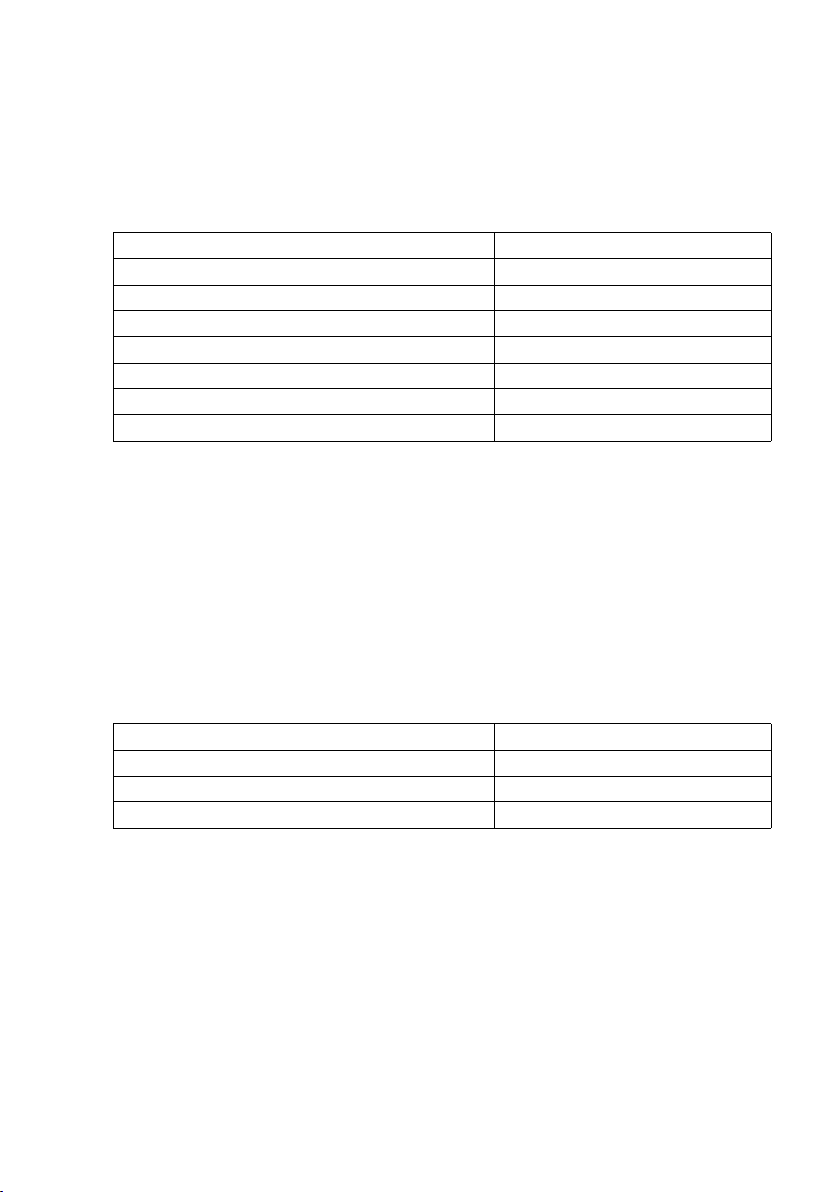
Information on ... ... is located here.
First steps
Making and accepting calls page 29
Using the network directories page 39
Reading eMails and using info services and network
mailboxes
Changing the display keys used for quick access to
functions
Changing settings for phone operation: local area code,
external line prefix, dialling plans, voice quality etc.
Providing directories page 89
Providing info services page 88
Backing up configuration page 94
If you have any questions about using your phone, please read the tips on
troubleshooting (
£ page 99) or contact our Customer Care team (£ page 99).
g
g
g
g
g
g
g
g
page 46
page 56
page 82
21
Page 22
Operating information
N
Operating information
Light emitting diodes (LED)
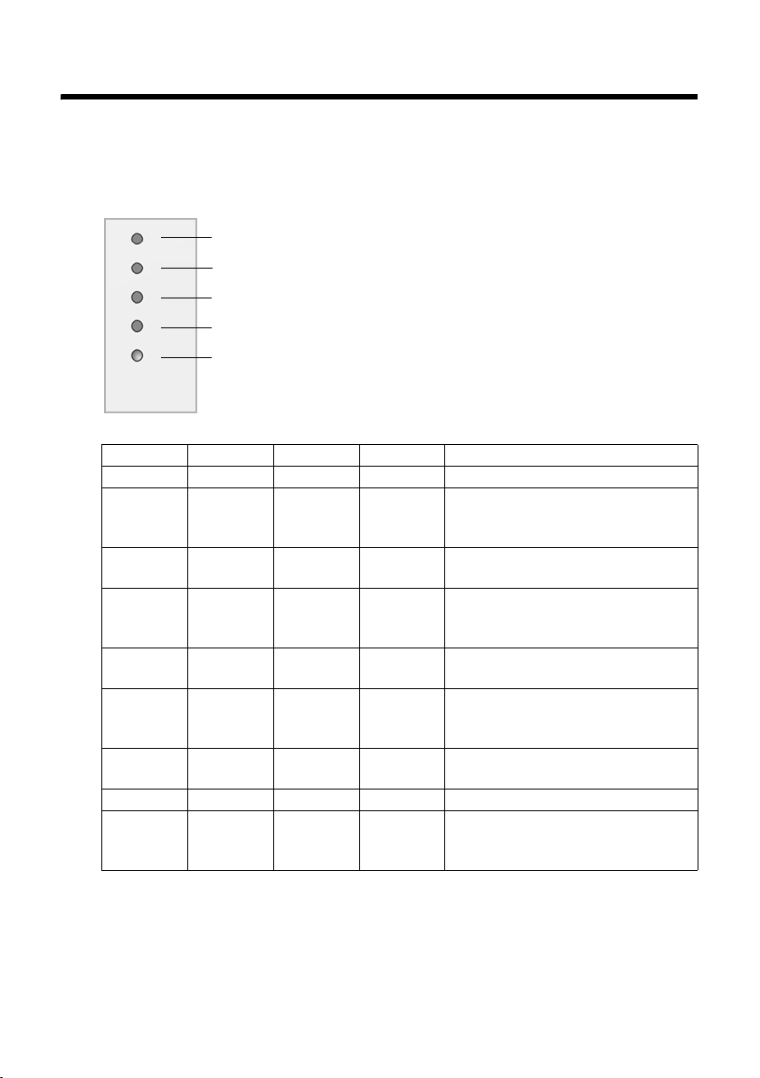
LEDs on the DECT Manager
DECT
Power/LA
VoIP
CALL
RESET
Power/LAN VoIP DECT CALL Description
Off Off Off Off No power supply / No supply voltage
Flashes
(every two
seconds)
On Off Off Off IP address assigned by DHCP, VoIP
On Flashes
On On Off Off All activated VoIP services
On On Flashes
On On On Off All registered base stations
On On On On At least one active call
Flashes
(every two
seconds)
Off Off Off No LAN connection or waiting for
(every four
seconds)
Flashes
(every two
seconds)
From top to bottom
Connection status to the base stations
Power supply status If the power supply is OK, the LED
indicates the LAN connection status.
VoIP connections status (activation and registration)
Active call display
Reset button (
Off Off At least one VoIP service activated,
Off At least one base station connected
(every four
seconds)
Off Off Firmware is being updated
£ page 24)
address to be assigned by the DHCP
server
service not (yet) available
waiting for SIP registration
successfully registered
connected
Other displays:
u The second LED from the top (Power/LAN) flickers when you are restoring the factory
settings to indicate that the resetting process will begin as soon as you release the
reset button (
u All LEDs light up for one second when the device has been successfully reset to static
IP addresses (
22
£ page 24).
£ page 25) or to DHCP (£ page 25).
Page 23
Operating information
N
N
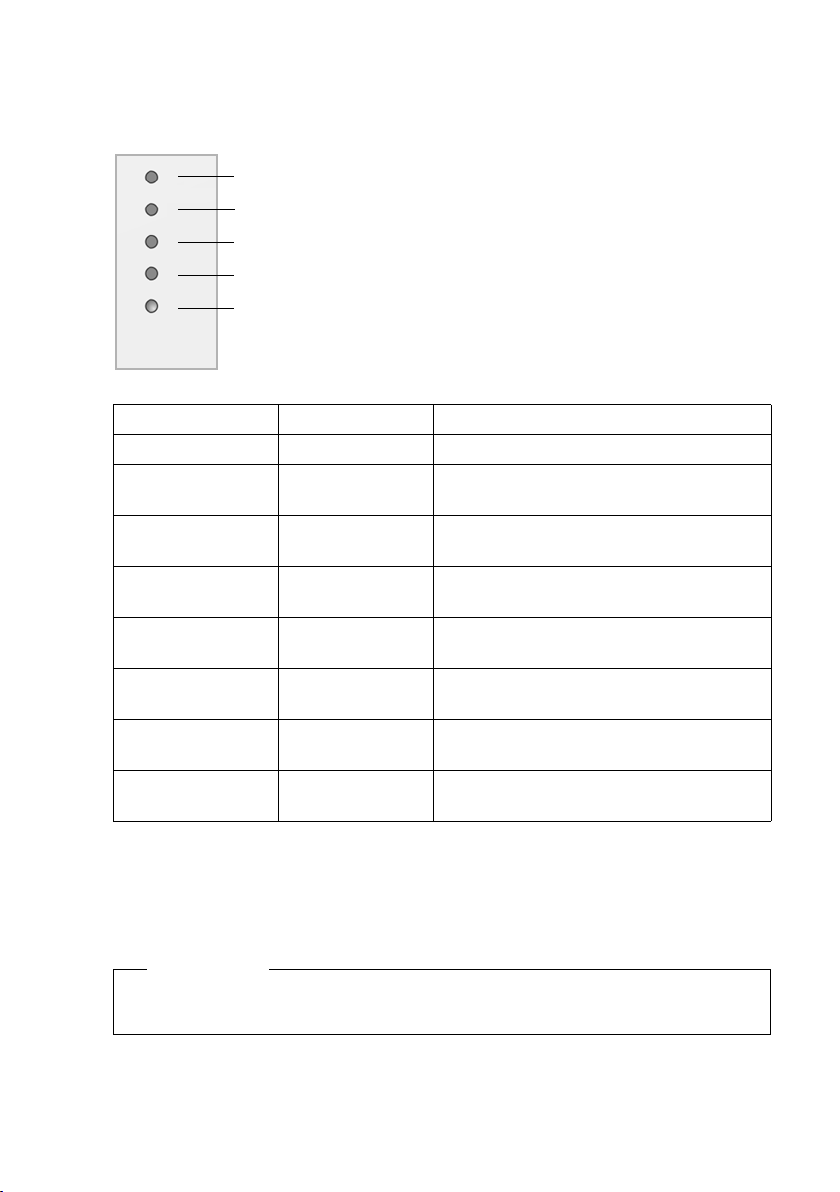
LEDs on the base stations
The Gigaset N720 IP PRO base stations contain two DECT modules with separate status
displays.
DECT 1
Power/LA
Power/LA
DECT 2
RESET
Power/LAN 1/2 DECT 1/2 Description
Off Off No power supply / No supply voltage
Flashes (once a
second)
On Off Connection established to DECT Manager,
Flashes (every two
seconds)
On On Base station DECT module ready, DECT
On Flashes (every four
Flashes (every four
seconds)
Flashes (every four
seconds)
Off The base station is looking for the DECT
Off Firmware is being updated, base station
seconds)
On Base station DECT module overloaded, DECT
Flashes (every four
seconds)
From top to bottom
Status of DECT module 1
Power supply status If the power supply is OK, the LED
indicates the LAN connection status.
Status of DECT module 2
Reset button (
£ page 24)
Manager
base station service not yet ready
service not active
synchronised
Base station DECT module ready, DECT not
synchronised
synchronised
Base station DECT module overloaded, DECT
not synchronised
Other displays:
u The second LED from the top (Power/LAN) flickers when you are restoring the factory
settings to indicate that the resetting process will begin as soon as you release the
reset button (
Please note
You can deactivate the base station LED displays using the Web configurator on the
DECT Manager (
£ page 24).
£ page 93).
23
Page 24
Operating information
Resetting the device settings
The devices have a reset button that you can
use to restore the default device settings.
This button is below the LEDs on the front of the
device.
Reset button
Resetting the device to factory settings
Caution
This function resets all the settings you have made. The procedure deletes the saved
data from the base stations and handsets. The base station's assignment to the DECT
Manager is cancelled.
This operation is available on the DECT Manager and on the base stations.
¤ Disconnect the power supply.
¤ Press and hold the reset button.
¤ Reconnect the device to the mains power supply while the reset button is depressed.
¤ Release the reset button again when the second LED from the top (Power/LAN) starts
flickering.
The device is reset to the factory settings.
Please note
If the device is powered via PoE, you must remove the LAN cable to interrupt the
power supply.
Resetting the IP configuration and password
The two procedures described below reset the DECT Manager's IP configuration settings
and the password for registering on the DECT Manager.
You will need to use this function if you can no longer access the system, e.g., because you
have forgotten the password for the Web configurator or you are experiencing problems
accessing the LAN.
You can reset the IP configuration either to specific static IP addresses or to dynamic
addressing (DHCP). You will then be able to access the DECT Manager again and you can
change the password or LAN configuration if required (
All the LEDs on the DECT Manager light up for one second to confirm that the two
resetting processes have been activated successfully.
24
£ page 59).
Page 25
Operating information
Resetting to static IP addresses
¤ Press the reset button and hold it for four seconds.
¤ Release the reset button.
¤ Press the reset button again for four seconds.
¤ Release it again.
The reset is carried out. The IP configuration is now set as follows:
Parameter Value for the reset
IP address type Static
IP Address DECT Manager 192.168.143.1
Subnet mask 255.255.0.0
Default Gateway 192.168.1.1
Preferred DNS server, Alternate DNS server 192.168.1.1
Password for access to the Web configurator admin
VLAN Tagging Off
Resetting to dynamic addressing (DHCP)
This allows you to specify that the DECT Manager will automatically receive an IP address
from a DHCP server in the local network.
¤ Press the reset button and hold it for four seconds.
¤ Release the reset button.
¤ Press the reset button for one second.
¤ Release it again.
¤ Press the reset button again for four seconds.
¤ Release it again.
The reset is carried out. The IP configuration is set as follows.
Parameter Value for the reset
IP address type Obtained automatically
Password for access to the Web configurator admin
VLAN Tagging Off
25
Page 26
Operating information
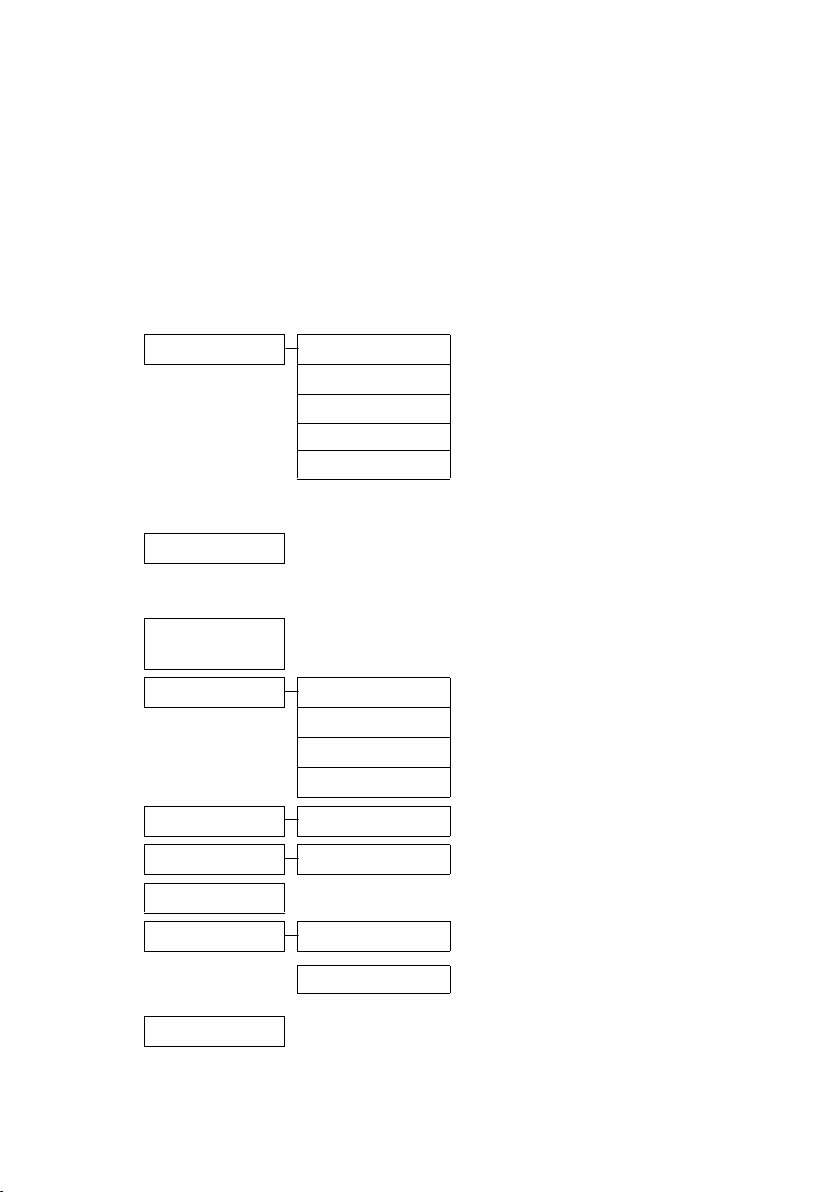
Menu tree (handsets)
You use the functions of your Gigaset N720 DECT IP Multicell System via a registered
handset. The functions of the telephone system are added to the handset menu, as
shown below. Handset-specific functions, e.g., local directory or organiser, are not
described here. Information about this will be found in the relevant handset user guide.
The availability of functions or their designations may differ on individual handsets.
On some Gigaset handsets, you can choose between Simplified (standard mode) and
Complete (expert mode) menu views. Menu options that are only available in expert
mode are marked with the • icon.
To open the main menu: press v when the handset is in idle status:
Select Services
Ç
È Info Centre
Please note: The Info Centre on the Gigaset C610H handset can be found in the Additional
Features menu.
É
Additional
Features
Ê
Call Lists
Ë
Messaging
Ì
Voice Mail
Í
Organiser
 Contacts
Next Call Anon. £page 35
Call Divert
Call Waiting
Do Not Disturb
Ringback Off
Depending on the PABX, additional services may be
offered.
List of available info services £ page 52
See user guide for your handset.
All Calls £ page 44
Outgoing calls
Accepted calls
Missed calls
eMail £ page 48
Play Messages £ page 47
See user guide for your handset.
Directory
Net Directories
£ page 37
£ page 37
£ page 38 Only functions supported by the
£ page 33
PABX are av ailabl e.
£ page 44
£ page 44
£ page 44
Information on local directory: see
user guide for your handset.
List of available public and
corporate directories
£ page 39
26
Ï Settings
£ page 56 Default settings: see user guide for your handset.
Page 27
Operating information
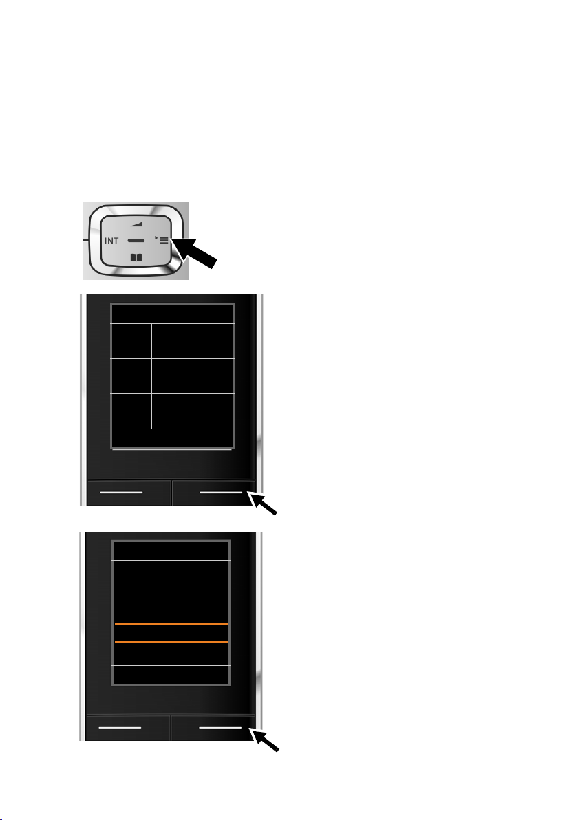
Understanding the operating steps
The operating steps have been shortened and are based on a Gigaset SL610H PRO
handset.
Example:
The display:
v ¢ Ç Select Services ¢ Do Not Disturb (³ =on)
means:
¤ Press right on the control key v to open
the main menu.
Settings
È
Ç
Ë
Ê
Â
á
Back OK
Settings
Next Call Anon.
Call Divert
Call Waiting
Do Not Disturb
Ringback Off
Back Change
É
Ì
Ï
´
¤ Press right, left, down and up on the
control key
Services submenu.
p to navigate to the Select
¤ Press the display key §OK§ to confirm your
selection.
¤ Press down on the control key
Do Not Disturb menu option is
highlighted.
s
until the
¤ Press the display key §Change§ to activate/
deactivate the function.
27
Page 28

Operating information
Settings
Next Call Anon.
Call Divert
Call Waiting
Do Not Disturb
Ringback Off
³
Back Change
The change is effective immediately and does
not need to be confirmed.
¤ Press the key below §Back§ to skip back to
the previous menu level.
Or
¤ Press and hold the end call key a to
return to idle status.
28
Page 29

Making calls
You can make calls using any handset registered to your Gigaset N720 DECT IP Multicell
System. Prerequisite: You are located in the cell of at least one of the base stations
registered to the telephone system.
The cells of the base stations together form the DECT wireless network of the telephone
system. You can initiate or answer calls on a handset across the whole wireless network
and change cells during a call (handover). Prerequisite for handover: The base stations
involved must be assigned to the same cluster and must be synchronised (
Each handset is assigned a send and receive connection (£ page 76).
If your Gigaset N720 DECT IP Multicell System is connected to a PABX that permits the
formation of groups, VoIP connections can also be assigned to groups. In this case, you
will also receive calls on your handset that have been sent to your group number.
The Gigaset N720 DECT IP Multicell System uses a VoIP PABX or the services of a VoIP
provider for Internet telephony. The availability of some phone functions depends on
whether they are supported by the PABX/provider and whether they have been enabled.
If necessary, you can obtain a description of the services from the operator of your PABX.
Please note
Depending on the specifications of your PABX, you may need to dial an access code
for calls outside the area covered by your VoIP PABX (
Calling
~c Enter the number and press the talk key. The number is dialled.
Or:
c~ Press and hold the talk key c and then enter the number.
Instead of the talk key
make a call in speaker mode.
In this user guide, each of these variants is indicated by "Press the talk key
The dialled number is shown on the display.
c, you can also press the speaker key don the handset to
£ page 82).
c".
Making calls
£ page 67).
Please note
If you use VoIP to make a call to the fixed line network, you may also have to dial the
area code for local calls (depending on the PABX/provider). This is not necessary if the
area code is entered in the configuration on the DECT Manager and the Activating
the area code for local calls using VoIP option is enabled (see Web configurator
£ page 83).
29
Page 30

Making calls
Please note
u You can cancel the dialling process with the end call key a.
u You can see the duration of the call while the call is in progress.
u Dialling using the directories (£ page 39) or the call and redial lists (£ page 44)
saves you entering numbers repeatedly.
u If all the Gigaset N720 DECT IP Multicell System connections are busy, the error
message Operation failed! is displayed.
u If all connections to the base station connected to your handset are busy, ". . ." is
shown on the display. The idle display then appears again.
Displaying the phone number you are calling (COLP)
Prerequisites:
u Your PABX/provider supports COLP (Connected Line Identification Presentation). You
may need to activate COLP.
u The called party has not activated COLR (Connected Line Identification Restriction).
For outgoing calls, the phone number of the connection on which the call is received is
displayed on the handset.
The displayed number may differ from the number you have dialled. Examples:
u The called party has activated call divert.
u The call is answered by another connection within a PABX system.
If there is an entry in the directory for this phone number, the corresponding name is
displayed.
Please note
u The actual number of the connection you have reached (or the assigned name) is
displayed instead of the called number during call swapping and consultation
calls.
u When the phone number is copied to the directory and the redial list, the dialled
number (not the displayed number) is copied.
Ending a call
a Press the end call key.
30
Page 31

Accepting a call
An incoming call on a Gigaset handset is indicated in three ways: by ringing, by a display
on the screen and by the flashing
You can accept the call on the handset in the following ways:
d and c keys.
¤ Press the talk key c to make the call via the receiver.
¤ Press the speaker key d to make the call via the loudspeaker.
¤ To deactivate the ringtone, press the §Silence§ dis pla y k ey. Yo u ca n a cce pt t he cal l as lo ng
as it is displayed on the screen.
Press the display key
§Reject§ or the end call key a to reject a call.
Calling Line Identification
When you receive a call, the caller's number or name is displayed if the following
prerequisites are met.
u Your PABX/provider supports CLIP, CLI and CNIP.
– CLI (Calling Line Identification): the caller's number is transmitted.
– CLIP (Calling Line Identification Presentation): the caller's number is displayed.
– CNIP (Calling Name Identification Presentation): the caller's name is displayed.
u You have requested CLIP or CNIP from your provider.
u The caller has requested CLI from the provider.
Call display
Example of display:
Gigaset SL610H PRO handset
on Gigaset N720 DECT IP Multicell System
Ø«Ú
Making calls
1234567890
Reject Silence
If the caller's number is in the handset's directory, the caller's name will be shown. If an
image has been stored, this will also be displayed.
Caller's number or name (via CLIP)
If no number is transmitted, External is displayed.
31
Page 32

Making calls
Display with CNIP
Ø«Ú
Doe, John,
Berlin
Reject Silence
Display with CNIP and CLIP
Ø«Ú
1234567890
Doe, John,
Berlin
Reject Silence
CNIP text, e.g.,
name and location
CLIP information
CNIP text
If you have CNIP, the CNIP information
registered with your provider for the
caller's number will be displayed, e.g.,
the name and, if applicable, the location.
If CLIP and CNIP are activated, the
respective details are displayed one
below the other.
If the number of the caller is stored in
your directory, the CLIP display is
replaced by the corresponding directory
entry.
Notes on phone number display (CLIP)
By default, the number of the caller is shown on the handset of your Gigaset telephone.
You do not have to make any other settings on your Gigaset telephone.
However, if the caller's number is not displayed, this can be due to the
following:
u You have not requested CLIP from your provider
u The PABX connected to the Gigaset N720 DECT IP Multicell System is not forwarding
all the information.
¤ Check the CLIP (phone number display) settings of your PABX and activate this
function if necessary. In the user manual for the device, search for the term "CLIP" (or
an alternative term such as "calling line identification", "phone number identification",
"caller ID" etc.). If necessary, contact the device manufacturer/supplier.
¤ Check whether your provider supports phone number display (CLIP) and that the
function has been activated for you. If necessary, contact your provider.
32
Page 33

Call waiting during a call
If you get another call while conducting a call, you will hear the call waiting tone (short
tone). If you have calling line identification (CLIP), the number of the waiting caller or the
corresponding directory entry is displayed. The caller will hear the ringing tone.
You have the following options:
Rejecting a call
§Reject§ Press the display key.
The call waiting tone is turned off. You remain connected to the first par ticipant. The other
caller will hear the busy tone.
Accepting the call/putting the first party on hold
§Accept§ Press the display key.
You are connected to the caller. The first call is placed on hold.
¤ Use q to switch between the participants (call swapping £ page 34).
Accept the call/end the first call
a Press the end call key.
The call is signalled as an incoming call. You can accept the call (£ page 31).
Please note
You can deactivate call waiting while a call is in progress (£ page 37).
Making calls
Initiating ringback
If the number you have called is engaged, you can arrange a ringback if your PABX/
provider supports this function.
§§Ringback§§ Press the display key to arrange for a ringback.
Ringback is initiated as soon as the line is free again.
Switching off ringback
If you decide you do not want a ringback, you can switch the function off again.
v ¢ Ç Select Services ¢ Ringback Off
33
Page 34

Making calls
Initiating a consultation call
You are talking to one participant and can call a second participant at the same time for
consultation.
You are conducting a call:
S Press the Recall key. This is only possible if the Recall key is enabled for call
transfer (
Or:
§Ext. Call§ Press the display key.
The previous call is placed on hold. The participant hears an announcement
or on-hold music, if this is set up on the VoIP PABX.
£ page 85).
~ Enter the second participant's telephone number.
The phone number is dialled. You are connected to the second participant.
If the participant does not answer, select the display key §End§ to return to the first
participant.
Please note
You can also select the second part icipant's phone number from a directory, the redial
list or a call list on the handset.
Ending a consultation call
§Options§ ¢ End active call
You are reconnected to the first call participant.
You can also end a consultation call by pressing the end call key a. The connection is
briefly interrupted and you will receive a recall. As soon as you answer the call, you are
reconnected to the first call participant.
Prerequisite: Transfer Call by On-Hook is not activated ("Transfer Call by On-Hook"
£ page 85).
Call swapping
You can speak to two callers one at a time (call swap).
Prerequisite: You are conducting a call and have called a second participant (consultation
call) or have accepted a waiting call.
¤ Use q to swap between the participants.
The caller you are currently speaking to is marked with the æ icon.
Ending a currently active call
§Options§ ¢ End active call
You are reconnected to the waiting caller.
34
Page 35

Transferring a call to another subscriber
You can transfer (connect) a call to another subscriber if your PABX/provider supports this
function.
You are conducting a call:
¤ Set up a consultation call (£ page 34).
When the participant answers:
¤ Announce the call, if necessary.
a Press the end call key.
The call on hold is transferred to the other participant's number.
Prerequisite: Transfer Call by On-Hook is activated ("Transfer Call by On-Hook"
£ page 85).
If the internal participant does not answer or the line is busy, press the §End§ display key to
return to the first call.
You can also press the end call key
participant picks up the call.
"Anonymous calling"
You can withhold your phone number for the next call (CLIR = Calling Line Identification
Restriction).
In idle status:
v ¢ Ç Select Services ¢ Next Call Anon.
Select and press
~ Enter the number or copy from the directory.
a when forwarding a call before the second
§OK§.
Making calls
§Dial Number§ / c
Press the display or talk key. The number is dialled.
35
Page 36

Making calls
Gigaset HDSP – telephony with brilliant sound quality
Your Gigaset telephone supports the G.722 wideband codec so you
can use it to make calls with brilliant sound quality (High Definition
Sound Performance).
The following are prerequisites for wideband connections on your telephone:
– You make the call from a wideband-capable handset.
– The G.722 codec is enabled for the phone system and selected for the handset
£ page 78).
(
– Your PABX/VoIP provider supports wideband connections.
– The recipient's phone supports codec G.722 and accepts the establishment of a
wideband connection.
Please note
Wideband telephony using the G.722 codec must be enabled in the DECT Manager
Web conf igurator
Multicell System. If wideband telephony is enabled, a maximum of four calls can be
conducted simultaneously per base station (eight in narrowband mode).
£ page 84. This setting applies to the entire Gigaset N720 DECT IP
36
Page 37

Setting phone functions
Setting phone functions
Activating/deactivating call waiting for calls
If the function is activated during a call, you will hear a call waiting tone to signal that
another caller is trying to get through (
When call waiting is deactivated, the caller will hear the busy tone if you are already
making a call.
Activating/deactivating call waiting
v ¢ Ç Select Services
q Press the control key to select Call Waiting.
§Change§ Press the display key to activate/deactivate the function (³ =on).
Using call forwarding (CF)
When forwarding a call, the call is diverted to another connection. You can use call
forwarding as a Gigaset N720 DECT IP Multicell System function or as a service offered by
the VoIP PABX/provider.
v ¢ Ç Select Services ¢ Call Divert
¤ You can enter data as follows:
Status
Select On/Off to activate/deactivate Call Divert.
Phone Number
Enter the number to which the call is to be diverted. You can enter a fixed line, VoIP or
mobile number.
When
Select All Calls/When Busy/No Answer.
All Calls: Calls are diverted immediately i.e., no more calls are signalled on your phone.
No Answer: Calls are diverted if no one accepts the call within several rings.
When Busy: Calls are diverted when your line is busy.
If the service is provided via the DECT Manager:
§OK§ Press the display key to activate the call forwarding function.
If you are using the service offered by the VoIP PABX or a provider:
§Send§ Press the display key.
£ page 33).
Please note
u Any call for the handset that has been diverted is entered in the call lists.
u If a call is forwarded to a participant who is not available (e.g., because their
handset is switched off ), the call is rejected after a short time.
37
Page 38

Setting phone functions
Do not disturb
You can activate the Do Not Disturb (DND) function if you do not want to receive any calls
and you do not want the phone to ring, if your PABX/provider supports this function. You
can still make calls when this function is activated.
v ¢ Ç Select Services ¢ Do Not Disturb
Status Select On/Off to activate/deactivate this function.
¤ Press the display key §Send§.
38
Page 39

Using directories
Using directories
The options are:
u The (local) directory for your handset (see handset user guide)
u Public online and classified directories (£ page 41)
u Online directories, provided by a PABX, e.g., a corporate directory and/or a private
directory (
The directories available are defined by the Web configurator of the DECT Manager
£ page 89).
(
Opening directories using the directory key
The directory key s (press down on the control key) for the handset is normally set as
follows:
u Press briefly to open the local directory
u Press and hold to open the selection of available online directories.
This assignment can be changed for each handset via the Web configurator on the DECT
Manager (
specific online directory. In this case, open the local directory by pressing and holding the
directory key.
The description below assumes the default assignment.
Opening the corporate directory using the INT key
The INT key u (press left on control key) on the handsets opens a corporate directory,
provided that this is set up via the Web configurator and can be accessed by the DECT
Manager. The directory to be opened can be set for each handset on the DECT Manager
£ page 77).
(
£ page 40)
£ page 77). The action "Press directory key briefly" can be assigned to a
Opening directories via the menu
You can access all available directories via the handset's menu:
v ¢ ÂContacts ¢ Directory Local directory
v ¢ ÂContacts ¢ Net Directories List of all online directories set up on the
DECT Manager
The directories are displayed with the names specified in the Web configurator.
Please note
If handsets are connected to a Gigaset N720 DECT IP Multicell System, it is not
possible to transfer entries from the local directory to another handset.
The administrator can use the Web configurator on the DECT Manager to transfer a
handset's local directory to a PC and to load the directory to other handsets from
£ page 79).
there (
39
Page 40

Using directories
Using corporate directories
You can use directories made available by a server in the corporate network on your
handset. The following formats are possible:
u Directory in LDAP format (LDAP = Lightweight Directory Access Protocol)
u Directory in XML format
u Personal directory in XML format
Prerequisite:
u The directories are available in the valid XML or LDAP format.
u They are configured and enabled on the DECT Manager (£ page 91).
Opening the directory
Prerequisite: The handset is in idle status.
u Press the control key (INT).
The directory opened is the one set to be opened via the INT key in the DECT Manager for
your handset (£ page 77).
Or:
v ¢ ÂContacts ¢ Network Directory
All available online directories are displayed.
q Select a directory and press §OK§.
Searching for and displaying an entry
q Scroll to the required entry.
Or:
~ Enter the name (or first few letters).
As soon as you press a key on the keypad, the phone goes into search mode.
You can enter up to eight characters. The first entry in the list which matches
your entry is displayed.
q If there are several matching entries, scroll to the desired entry.
¤ Press the display key §View§ or w to display the entry.
Dialling a number from a corporate directory
The corporate directory is opened using the INT key u(press left on control key).
u Open a corporate directory.
q Select an entry.
c Press the talk key. The number is dialled.
You hear the busy tone if:
u The phone being called is not available (handset switched off, out of range).
u The call is not answered within a certain time (specified on the PABX).
40
Page 41

Using directories
Using online directories
You can use public online directories (online directories and classified directories, e.g.,
"Yellow Pages"). Prerequisite: The online directories are enabled on the DECT Manager
£ page 89) and the DECT Manager can access the Internet via its LAN connection.
(
Exclusion of liability
This service is country-specific. Gigaset Communications GmbH assumes no guarantee
or liability for the availability of this service.
The service may be discontinued at any time.
Opening an online directory/Yellow Pages
Prerequisite: The handset is in idle status.
s Press and hold.
Or:
v ¢ ÂContacts ¢ Network Directory
This opens the list of online directories.
q Select a directory (online directory or Yellow Pages) from the list and press
§OK§.
This establishes a connection to the online directory or the Yellow Pages.
If there is only online net directory available, a connection is immediately established if
you press and hold down the control key
s.
Searching for an entry
Prerequisite: You have opened the online directory/Yellow Pages.
¤ You can enter data in the following fields:
Surname: (Online directory) or
Category/Name:
City: Enter the name of the city/location in which the party you are searching for
Or:
Number: Enter the number (max. 30 characters).
(Yellow Pages)
Enter the name, part of a name or the category (max. 30 characters).
lives (max. 30 characters).
If you have already completed a search, the names of the cities you last
entered are displayed (maximum of five).
You can enter a new name or select one of the city names displayed using
and confirm with
§OK§.
¤ Press the display key §Search§ or w to start the search.
You must make an entry in either Surname or Category/Name: and in City, or in Number.
Searching by number is only possible if supported by the net directory you have selected.
s
Please note
Instructions for entering text on your handset are set out in the handset user guide.
41
Page 42

Using directories
A list of the cities/locations found is displayed if the search returns more than one result:
q Select city.
If the name of a city/location is longer than one line, it is abbreviated. Select
§View§ to view the complete name.
If no matching city is found: press
entries for Category/Name and City are copied and you can change them.
§Search§ Press the display key to continue the search.
A corresponding message will appear on the display if no party is found to match the
search criteria. You have the following options:
§Change§ to change the search criteria. The
¤ Press the display key §New§ to start a new search.
Or
¤ Press the display key §Change§ to change the search criteria. The name and city/location
are copied over and you can change them.
No hits are displayed if the list of hits is too large. A message to this effect is displayed.
¤ Press the display key §Refine§ to start a refined search (£ page 43).
Or
¤ Depending on the provider, you can view the list if the number of hits is displayed.
Press the display key
Search result (hit list)
The search result is shown as a list on the display. Example:
§View§.
Online Directory 1/50
Doe, John
+49123456789
Parkstrasse 11
Berlin 12345, Germany
View Options
1. 1/50: Consecutive number/total number of hits (only the consecutive number is displayed if the
total number of hits >99).
2. Four lines including party's name, category, telephone number and address (possibly
abbreviated). If a fixed line number is not available, the mobile number (if available) is displayed.
42
1
2
Page 43

Using directories
You have the following options:
¤ You can scroll through the list with q.
¤ Press the display key §View§. This displays the full details of the entry (name, category
where applicable, address, telephone numbers). You can scroll through the entry with
q.
Use
§Options§ to access the following options:
Refine Search
Refine search criteria and restrict hit list (
New Search
Start a new search.
Copy to Directory
Copy an entry to the local directory. If an entry contains several numbers, they are
displayed in a selection list. A new entry is created for the selected number. The
surname is transferred to the Surname field of the local directory.
£ page 43).
Calling subscribers
Prerequisite: A hit list is displayed.
¤ Select the entry and press the talk key c.
If the entry only contains one phone number, this is the one that is dialled.
A list of numbers appears if there is more than one number.
¤ Using q, select a number and press the display key §Dial§.
Starting a refined search
You can use the search options available in the refined search (first name and/or street) to
limit the number of hits returned by a previous search.
Prerequisite: A search result is displayed (hit list with multiple entries or a message
indicating too many hits).
§Refine§ Press the display key.
Or
§Options§ ¢ Refine Search
Select and press
The search criteria from the previous search are copied and entered in the corresponding
fields.
Surname: (Online directory) or
Category/Name
City: Name of the city from the previous search is shown (cannot be changed).
Street: If necessary, change the name of the street (max. 30 characters).
First Name: (only in the online directory)
§Search§ Start refined search.
: (Yellow Pages)
If necessary, change the name/business type or enter additional details.
If necessary, enter the first name (max. 30 characters).
§OK§.
43
Page 44

Using the call lists
Using the call lists
The following call lists are available:
All Calls All outgoing, accepted and missed calls.
Outgoing calls The last 20 numbers dialled (redial list).
Accepted calls Calls that were answered (max. 15).
Missed calls Calls that were not answered (max. 15).
If the list contains entries that you have not yet viewed, the display
shows the
be accessed via the message key
Calls are stored in the lists in chronological order. When the maximum number is reached,
the next entry overwrites the oldest one. Incoming calls can only be stored if the CLIP
information is provided (
£ page 31).
Viewing entries
You can open the call lists in idle status:
§Calls§ Press the display key
Or via the menu:
v ¢
Ê
q Select the required list and press §OK§.
Please note
You can also open the redial list (outgoing calls) by pressing the talk key c. The list
of missed calls can also be opened by pressing the message key
™ icon and the number of new entries. The list can also
f (£ page 46).
f.
List entry
All calls
l Frank
™
14.09.11, 15:40
š 089563795
14.05.11, 15:32
™ ...0123727859362922
14.05.11, 15:07 [3]
View Options
u Phone number of the caller/called party. If the number is saved in the local directory,
the name is displayed. If the number is not in the local directory, the corporate
directories are searched.
u Date and time of the call. For missed calls, the number of attempts is also indicated.
The information displayed is determined by the information transferred by the caller and
whether or not the caller appears in the directory.
44
The calls are displayed in chronological order, from the
most recent through to the oldest.
An icon is shown in front of each entry to indicate whether
it is an outgoing (
Information on the entry:
u List type (in header)
u Status of entry, bold: new entry
u Number or name of caller
u Date and time of call (if set).
š), accepted (›) or missed (™) call.
Page 45

Using the call lists
If the caller has activated CLIP (= Calling Line Identification Presentation), the caller's
phone number is identified. The caller can then be identified by this number if he or she
is saved in a directory.
Displaying detailed information
§§View§§ Press the display key. The information available is displayed, with the phone
number as a minimum.
Dialling a number from a list
You have the following options for dialling a phone number from a list:
q Scroll through the list to the required name.
c Press the talk key. The number is dialled.
Or:
§§View§§ Press the display key to show the entry.
c Press the talk key. The number is dialled.
Copying an entry from the call list to the local directory.
q Scroll through the list to the required entry.
§§Options§§ Press the display key.
q Select Copy to Directory and press §§OK§§ to confirm.
The directory opens. You can create a new entry in the directory or edit an existing one.
Deleting an entry/list
q If you want to delete a particular entry, scroll through the list to the relevant
entry.
§§Options§§ Press the display key.
q Select Delete entry or Delete All and press §§OK§§ to confirm.
You must confirm the action again.
45
Page 46

Displaying messages
Displaying messages
The following types of messages are displayed:
u Voice mails on network mailboxes (see below)
u Missed calls (£ page 44)
u eMails (£ page 48)
u Missed appointments (see user guide for your handset)
The message key f provides access to all your messages.
Receipt of a new message is indicated as follows:
u By the message key f flashing
u By an icon on the idle display:
Ð
V
10:30
21 Nov
Missed calls
New voice mails
à œ Ë n
02 10 08 05
Calls Calendar
Using the network mailbox
Your VoIP PABX/provider offers answering machines on the network, known as network
mailboxes.
Each network mailbox accepts incoming calls made via the corresponding line (VoIP
phone number). To record all calls, a network mailbox must be set up for each VoIP
connection.
The network mailbox is configured for each handset using the Web configurator on the
DECT Manager and can also only be activated or deactivated there (
Displaying new messages in the handset's idle display
If a new message is present on the network mailbox assigned to the handset, the Ã
icon and the number of new messages are shown on the idle display. The f message
key flashes.
New eMails
Missed appointments
£ page 77).
46
Page 47

Displaying messages
Playing back a message
Calling the network mailbox via fast access
Press and hold.
You are connected straight to the network mailbox.
d If necessary, press the speaker key.
You will hear the network mailbox announcement.
Calling the network mailbox via the menu
Ì
v ¢
You are connected straight to the network mailbox.
Calling the network mailbox using the message key
Under the message key f you will find a list of the different types of message, e.g.,
missed calls, eMail or network mailbox.
The following is displayed (Gigaset SL610H PRO as an example):
. . . (4)
Network Mailbox (2)
. . . (3)
Voice Mail
Messages & Calls
¢ Play Messages
If there are new messages in the network mailbox, the list
entry is shown in bold. The number of new messages is
shown in brackets following the list entry.
If there are no new messages, no number is shown after the
list entry for the network mailbox. The number of messages
stored in the network mailbox is not displayed.
Back OK
f Press the message key.
s Select the network mailbox entry and press §OK§.
You are connected directly to the network mailbox and can hear its announcement.
Messages can generally be played back using your handset keypad (digit codes). Listen to
the announcement.
Please note
u The network mailbox is automatically called via the corresponding connection.
An automatic area code specific to your phone is not prefixed.
u Network mailbox messages can generally be played back using your phone's
keypad (digit codes). For VoIP, you need to define how the digit codes should be
converted to DTMF signals and transmitted (
£ page 84).
47
Page 48

Displaying messages
eMail notifications
You can receive eMail-messages on your handset if the name of the incoming eMail server
and your personal access data (account name, password) have been stored on the DECT
Manager using the Web configurator and you have specified that you want to be notified
when a new eMail arrives (
Prerequisite: The telephone system connects to the incoming eMail servers regularly and
checks for new messages. This connection is made every 15 minutes by default, although
the administrator can change this default setting (
Your handset display will show when a new eMail message has been received. On the
Gigaset SL610 PRO, for example, an advisory tone sounds, the message key
and the Ë symbol is displayed in the idle display.
£ page 81).
£ page 75).
Please note
If new eMail messages have been received, pressing the message key f will
display them in the eMail list.
Using the handset, you can display the sender, date/time of receipt, the subject and the
message text (abbreviated if necessary) for each eMail in the incoming eMail list
£ page 48).
(
Please note
If you have also activated the authentication of the phone with the incoming eMail
server via a secure connection in the Web configurator (TLS authentication) and this
fails, the eMail messages are not downloaded to your phone.
In this case, pressing the flashing message key
Certificate error -.
fwill display the message
¤ Press the display key §OK§ to confirm the message.
¤ The Security Settings Web page on the DECT Manager (£ page 71) tells you why
the secure connection could not be established and what you can do.
f flashes
Opening the incoming eMail list
Prerequisites:
u You have set up an eMail account with a provider.
u The incoming eMail server uses the POP3 protocol.
u The name of the incoming eMail server and your personal access data (account name,
password) are stored in the DECT Manager for your handset (
On the handset:
Ë
v ¢
Or, if new eMail messages have been received (message key f flashes):
Messaging ¢ eMail
f ¢ eMail
The phone establishes a connection to the incoming eMail server. A list of eMail messages
that are stored there is displayed.
48
£ page 81).
Page 49

Displaying messages
New unread messages appear above old read messages. The most recent entry appears
at the head of the list.
The following details are displayed for each eMail: name or eMail address of the sender
(one line, abbreviated if necessary) and date and time (date and time will only display
correct values if sender and recipient are located in the same time zone).
Example display on the Gigaset SL610H PRO handset:
eMail Incoming
Frank.Miller@mailp.com
10.10.11 15:40
Happy Birthday
Anna Sand
10.10.10 10:38
1
2
Read Delete
1 eMail address or name transmitted by the sender (abbreviated if necessary)
Bold: new message.
All eMail messages that were not on the incoming eMail server when the inbox was last opened
are identified as "new". All other eMails are not marked, regardless of whether or not they have
been read.
2 Date and time of receipt of eMail message
If the inbox on the incoming eMail server is empty, No entries will appear in the display.
Please note
Many eMail providers activate spam protection measures by default. eMail messages
classified as spam are stored in a separate folder and are therefore not shown in the
incoming eMail list.
Some eMail providers allow you to deactivate spam protection or show spam eMails
in the incoming mail list.
Other eMail providers may send a message to the inbox when a new spam eMail is
received. This is to inform you that a suspected spam eMail has been received.
The date and sender of this mail are repeatedly updated, so that it is always displayed
as a new message.
Messages when establishing a connection
The following problems may occur when connecting to the incoming eMail server. The
messages are displayed in the display for a few seconds.
Server not accessible
The connection to the incoming eMail server could not be established. This may have
the following causes:
– Incorrect entry for the name of the incoming eMail server (
¢ Web configurator,
£ page 81).
49
Page 50

Displaying messages
– Temporary problems with the incoming eMail server (server is down or is not
connected to the Internet).
¤ Check settings in the Web configurator.
¤ Try again later.
Currently not possible
The resources required by your phone to make the connection are busy, e.g., because
the maximum permitted number of DECT connections has already been reached.
¤ Try again later.
Login failed
Error when logging in to the incoming eMail server. This may have the following cause:
– Incorrect entries for name of incoming eMail server, user name and/or password.
¤ Check settings (¢ Web configurator, £ page 81).
– The eMail provider may only permit POP3 access at certain intervals.
¤ Try again a few moments later.
Mailbox settings incomplete
Incomplete entries for name of incoming eMail server, user name and/or password.
¤ Check/add to settings (¢ Web configurator).
Viewing the message header and text of an eMail
Prerequisite: You have opened the incoming mail list (£ page 48).
q Select an eMail entry.
§Read§ Press the display key.
The subject of the eMail (maximum 120 characters) and the first few characters of the text
are displayed.
Example display on the Gigaset SL610H PRO handset:
eMail
Subject:
Invitation
Tex t:
Hi Anna, I
passed my test!
Back Options
1 Subject of the eMail message. A maximum of 120 characters are displayed.
2 Tex t of the eMail message (abbreviated if necessary).
1
2
a Press the end call key to return to the incoming message list.
Please note
If the eMail contains anything other than text, the message eMail can’t be displayed
will briefly appear.
50
Page 51

Displaying messages
Viewing eMail sender's address
Prerequisite: You have opened the eMail notification to read it (£ page 50).
§Options§ ¢ From
Select and press
The sender's eMail address is displayed, over several lines if necessary (maximum 60
lines).
§Back§ Press the display key to return to the incoming message list.
Example display on the Gigaset SL610H PRO handset:
eMail
From:
Anna.Sand@mailp.com
Back Options
§OK§.
Deleting eMail messages
Prerequisite: You have opened the incoming eMail list (£ page 48) or the header or
sender's address for an eMail is displayed (
§Options ¢ Delete
Select and press
§Yes§ Press the display key to confirm the security prompt.
The eMail is deleted from the incoming eMail server.
§OK§.
£ page 50):
51
Page 52

Info centre – continuous Internet access from your phone
Info centre – continuous Internet access from your phone
You can use your phone to request info services provided specifically for the phone. The
services available are set via the Web configurator on the DECT Manager (
Info services can be:
u Online content from the Internet
u Information provided about the PABX.
Please note
You can launch the info centre and display info services with any registered Gigaset
SL610H PRO, C610H, SL400H, S810H and E49H handset.
With some of these handsets, you can launch the info centre directly from the main
menu. For others (e.g., Gigaset C610H), you will find the info centre in the submenu
É Additional Features.
Starting the info centre, selecting info services
You can select info services (applications, apps) made available by the server.
Examples:
On the Gigaset SL610H PRO, S810H and SL400H handsets:
v ¢ È Info Centre
On the Gigaset C610H handset:
v ¢ É Additional Features ¢ Info Centre
Your info centre menu i.e., a list of available info services is displayed. You can navigate
between the info services.
s Select the info service and press §OK§.
To access certain info services (personalised services), you have to log in with a user name
and password. In this case, enter your access data as described in the "Login for
personalised info services" section on page 53.
£ page 88).
52
Page 53

Info centre – continuous Internet access from your phone
Messages when loading requested information
The information is loaded from the Internet. Wait a few seconds until the information is
displayed. The display shows Please wait....
If the information for an info service cannot be displayed, one of the following messages
appears:
Requested page can’t be reached.
Possible causes of this are:
u Time limit exceeded (timeout) when loading the information
u The Internet server for the info services cannot be accessed.
¤ Check your Internet connection and repeat the request at a later date.
Coding error on requested page
The content of the requested info service is coded in a format that the handset cannot
display.
Can’t display requested page
General error when loading the info service.
Login failed.
Login has failed. Possible causes of this are:
u You have not entered your login data correctly.
¤ Reselect the info service and repeat the login process. Please remember that data
is case sensitive.
u You are not entitled to access this info service.
Login for personalised info services
If a special login process with user name and password is required to access an info
service, the following is displayed after the service has been called up:
Authent. Name
Enter the username supplied by the provider of the info service.
§Save§ Press the display key.
Password
Enter the password associated with this username.
§Save§ Press the display key.
If login was successful, the requested info service is displayed.
If login failed, a message to this effect appears on the display
loading requested information, page 53.
Please note
Please remember that login data is case sensitive. General instructions on entering
text can be found in the handset user guide.
£ Messages when
53
Page 54

Info centre – continuous Internet access from your phone
Operating the info centre
Depending on the type of info service requested, you can perform the following
operations:
Scrolling within an info service
¤ You can use s to scroll downwards within an info service, and t to scroll up (back).
Skipping back to the previous page
¤ Press the left display key.
Skipping back to the info centre menu
¤ Briefly press the end call key a.
You want to go offline:
Press and hold the end call key a; the handset returns to idle status.
Selecting a hyperlink
Hyperlink to further information:
If the page contains a hyperlink to further information, this is indicated by theg icon.
If a page with hyperlinks is opened, the first hyperlink is highlighted.
¤ Using the control keys (s and/or t) as required, you can navigate to the hyperlink
that you would like to select. The hyperlink is then highlighted by bars.
¤ Press the right display key §Link§ to open the relevant page.
Hyperlink to a phone number:
If a hyperlink contains a phone number, you can copy the number to the local directory
or call the number directly (Click-2-Call functionality).
¤ Select the hyperlink using the s and/or t keys, as required.
¤ You can identify a hyperlink of this type by the fact that §call§ is shown above the right
display key.
¤ Press the display key Ó to copy the phone number to the local directory on your
handset.
Or:
¤ Press §call§ to call the stored number.
54
Page 55

Info centre – continuous Internet access from your phone
Depending on the provider, if you press §call§,
u The number is dialled directly
u The number appears first in the display, in which case you must first confirm the
number before it is dialled.
¤ If you press §Yes§, the number is dialled.
Or:
¤ If you press §No§, the page is displayed again with the hyperlink. The number will not
be dialled.
Entering text
¤ If necessary, use q to navigate to the line containing the field into which you want to
enter text. The cursor flashes in the text field.
¤ Enter the text using the keys on your handset.
¤ If necessary, navigate to other text fields to complete them or make a selection (see
below).
¤ Press the right display key to complete the entry and send the data.
Making selections
¤ If necessary, use q to navigate to the line in which you would like to make a selection.
¤ Press left or right on the control key several times to make the required selection.
¤ Useqto navigate to other selection fields and make your selection as described
above.
¤ Press the left display key to complete the selection and send the data.
Setting options
¤ Use q to navigate to the line containing the option. The line is highlighted.
¤ Activate or deactivate the option via the control key v (press right) or the left display
key (e.g.,
§OK§).
¤ If necessary, navigate to other options or text fields to set or complete them.
¤ Press the left display key (e.g., §Send§) to complete the entry and send the data.
55
Page 56

System settings and settings on the handset
System settings and settings on the handset
System settings are made via the Web configurator on the DECT Manager (£ page 58)
and cannot be changed using the handsets.
This applies in particular for:
u Registering and de-registering the handset to the telephone system, handset name.
u All settings for the VoIP account used by a handset for calls.
u Settings for the network mailbox and the eMail account.
u Configuration of online directories.
Handset-specific settings are preset on your Gigaset. You can change these settings.
This applies, for example, for
u Display settings, such as language, colour, backlight etc.
u Settings relating to ringtones, volume, speaker profiles etc.
Information about this can be found in the user guide for the relevant handset.
Date and time
Date and time are set in the Web configurator of the DECT Manager (£ page 92) and are
synchronised system-wide on all base stations and Gigaset handsets.
Synchronisation is carried out in the following cases:
u If the date or time has been changed on the DECT Manager.
u If a handset is registered to the telephone system.
u If a handset is switched off and switched back on again, or is outside the wireless range
of the telephone system for more than 45 seconds and then comes back into range.
u Automatically every night at 4.00 am.
You can change the date and time on the handset. This setting only applies for that
handset and will be overwritten when the next synchronisation takes place.
The date and time are displayed in the format set for that handset.
Please note
The date and time can only be set locally on handsets which only support the simple
GAP standard. No synchronisation is carried out.
Quickly accessing functions
You can select the assignment of the display keys in idle status from a range of telephone
system functions for your handset.
Prerequisite: The handset used supports the individual assignment of display keys in idle
status.
¤ Press and hold the left or right the display key. The list of possible key assignments is
opened.
¤ Select a function and press §OK§.
56
Page 57

System settings and settings on the handset
The following basic functions can also be selected in addition to the functions provided
by the handset for assigning display keys:
eMail
Opens the eMail submenu for receiving and reading eMail notifications (
Ë
v
More Functions...
Select and press
Call Lists Assign the call lists menu to a key.
Withhold Number Restrict Calling Line Identification for the next call
Call Divert Assign the menu for setting and activating/deactivating call
PBX Control Access to PABX services.
eMail Opening the eMail submenu for receiving and reading eMail
Info Centre Start the info centre and open the list of available information
Net Directories Displaying the list of all network directories and providers of
Central Net Dir. Opening a corporate directory (
Public Net Dir. Opening the public directory (
¢
Messaging
¢ eMail
§OK§; you can then also select from the following additional functions:
¢
Ê
Call Lists
£ page 37):
£ page 48):
£ page 52).
£ page 39)
v
£ page 35).
(
forwarding to a key (
v ¢ Ç Select Services ¢ Call Divert
v ¢ Ç Select Services ¢ PBX Control
This function is only available if your Gigaset N720 DECT IP
Multicell System PRO is connected to a Gigaset T500 PRO or
T300 PRO PABX and services are provided via a RAP server
£ page 88).
(
notifications (
v ¢ËMessaging ¢ eMail
services – go online (
v ¢ Additional Features ¢ Info Centre
network directories (
v ¢ ÂContacts ¢ Net Directories
£ page 40). If there is more
than one, the list of corporate directories is opened.
£ page 41). If there is more
than one, the list of public directories is opened. If there are
directories from several providers, the list of providers is
opened.
£ page 48):
Starting a function
The function is displayed in the bottom display line above the display key (abbreviated, if
necessary). To start the function, you then simply need to press the button.
When the handset is in idle status:
¤ Press the display key briefly.
The submenu opens and the function is performed.
57
Page 58

Configuring the system on the DECT Manager
Configuring the system on the DECT Manager
Use the Web configurator to set up your Gigaset N720 DECT IP Multicell System and
configure your DECT network.
u Set up the DECT network, register and synchronise the base stations.
u Make basic settings for the VoIP connections and register and configure the handsets
you wish to use in the DECT network.
u You can make additional settings, e.g., meet particular prerequisites for connecting
the handsets to a corporate network or adjust the voice quality on VoIP connections.
u Use the DECT Manager to save data required to access specific services on the Internet.
These services include access to public online directories and to the incoming eMail
server for eMail accounts, as well as synchronising the date/time with a time server.
u You can save your DECT Manager's configuration data as files on your PC and reload
these onto your DECT Manager in the event of an error. You can arrange firmware
updates for the DECT Manager.
u Manage the directories on registered Gigaset handsets (save to PC, compare them
with one another or against a directory on your PC).
Using the Web configurator
Connecting the PC to the Web configurator on the DECT Manager
Prerequisites:
u A standard Web browser is installed on the PC, e.g., Internet Explorer version 8.0 or
higher, or Firefox version 4.x or higher.
u The DECT Manager and PC are directly connected to one another in a local network.
The settings of any existing firewall installed on your PC allow the PC and DECT
Manager to communicate with each other.
Please note
u Depending on your VoIP PABX/VoIP provider, it is possible that you will be unable
to change individual settings in the Web configurator.
u While you are connected to the Web configurator, it is blocked to other users.
Simultaneous access is not possible.
¤ Launch the Web browser on your PC.
¤ Enter www.gigaset-config.com in the address field of the Web browser.
The known devices with this name are displayed.
If several devices are found, select your DECT Manager using the MAC address.
A connection is established to the Web configurator for the DECT Manager.
58
Page 59

Configuring the system on the DECT Manager
If connecting to www.gigaset-config.com does not produce any results:
¤ Establish the DECT Manager's current IP address.
¤ Enter http:// and the current IP address for the DECT Manager in the address field of
the Web browser (for example: http://192.168.2.10).
Please note
The IP address is assigned dynamically via your local network's DHCP server. You can
find the DECT Manager's current IP address on th e DHCP se rver in t he list of registered
DHCP clients. The computer name for the DECT Manager is N720-DM-PRO. The MAC
address can be found on the rear of the device. If necessary, contact the network
administrator for your local network.
Once a handset is registered on the system, you can also find the IP address via the
Info menu on the handset (
Your DECT Manager's IP address may change occasionally depending on the DHCP
server settings (
£ page 64).
Logging into/off the Web configurator
Once you have successfully established the connection, the login screen is displayed in
the Web browser.
£ page 103).
You can select the language in which you want the menus and Web configurator
dialogues to be displayed.
¤ If necessary, click to open the list of available languages.
V
¤ Select the language.
The Web page is reloaded in the selected language. Reloading may take some time.
¤ Enter the password in the bottom field of the Web page (default setting: admin) to
access the Web configurator functions.
¤ Click OK.
59
Page 60

Configuring the system on the DECT Manager
Please note
u You should change the password for security reasons (£ page 71).
u If you do not make any entries for a lengthy period (approx. 10 minutes), you are
automatically logged off. The next time you try to make an entry or open a Web
page, the login screen is displayed again. Enter the password again to log back in.
u Any entries that you did not save on the DECT Manager before automatic logoff will
be lost.
Understanding the structure of the Web configurator pages
The Web configurator pages contain the following UI elements (example):
Navigation area Menu bar
(tabs)
Working area Buttons
Please note
The Help function includes a link to a website where you can obtain further
information.
60
Help
Page 61

Configuring the system on the DECT Manager
Menu bar
The Web configurator menus are displayed as tab pages in the menu bar. You will find an
overview of the Web configurator menu on
The following menus are available:
Settings
The menu allows you to make Settings on the DECT Manager.
If you select the Settings menu, a list of this menu's functions is displayed in the
navigation area.
Status
The menu supplies information about the configuration and status of the DECT
Manager and base stations.
Log Off
You will find the Log Off function at the top right of each Web page, above the menu
bar.
£ page 63.
Caution
Always use the Log Off function to end the connection to the Web configurator. If, for
example, you close the Web browser without logging off beforehand, access to the
Web configurator may be blocked for a few minutes.
Navigation area
The functions of the menu (£ page 61)
selected in the menu bar are listed in the
navigation area.
If you select a function, the associated page
containing information and/or input fields
opens in the working area. The selected
function is highlighted in orange.
If a function is assigned subfunctions, these
are listed below the function as soon as you
select the function (in the example Network
and connectors).
The relevant page for the first subfunction
(highlighted in orange) is displayed in the
working area.
61
Page 62

Configuring the system on the DECT Manager
‰
‰
Working area
Depending on the function selected in the navigation area, information or dialogue
boxes are displayed in the working area that allow you to make or change your DECT
network settings.
Making changes
You can make settings via input fields, lists or options.
u There may be restrictions regarding the possible values for a field e.g., the maximum
number of characters, entering special characters or certain value ranges.
u To open a list, click . You can choose between default values.
u There are two kinds of options:
– Checkboxes: You can activate one or more options from a list. Active options are
indicated by , non-active options by . You can activate an option by clicking
. The status of the other options in the list does not change. You can deactivate
an option by clicking .
– Alternative options (radio buttons): The active option in the list is indicated by ,
and the non-active by . You can activate an option by clicking . The previously
activated option is deactivated. You can only deactivate an option by activating
another option.
Applying changes
As soon as you have made your change on a page, save and activate the new setting on
the DECT Manager by selecting Set.
If your entry does not comply with the rules for this field, an appropriate error message is
displayed. You can then repeat the input.
V
.
Caution
Changes that have not been saved on the DECT Manager are lost if you move to
another Web page or the connection to the Web configurator is lost, e.g., due to
exceeding the time limit (
£ page 60).
Buttons
Buttons are displayed in the bottom section of the working area. Depending on the
current function of a Web page, various buttons are displayed. The functions of these
buttons are described in the respective function below.
The most important buttons are:
Cancel
Reject changes made on the Web page and reload the settings that are currently saved
in the DECT Manager to the Web page.
Set
Store changes made on a Web page in the DECT Manager.
62
Page 63

Configuring the system on the DECT Manager
Opening Web pages
A brief outline of how to navigate to the individual Web configurator functions is given
below.
Example
Defining dialling plans:
Settings ¢ Tel e ph ony ¢ Dialling Plans
To open the Web page, proceed as follows after login:
¤ Select the Settings menu in the menu bar.
¤ Click the Te le p ho ny function in the navigation area.
The Te le p ho ny subfunctions are displayed in the navigation tree.
¤ Select the Dialling Plans subfunction.
Web configurator menu
Settings Network and
connectors
VoIP providers List of VoIP providers
Handsets
Telephony Dialling Plans
Info Services
Online directories
Management Date & Time
IP Configuration £ page 64
Base station registration
Base station settings
Base station events
Base station synchronisation
Security Settings
£ page 67
£ page 69
£ page 71
£ page 70
£ page 71
£ page 73
£ page 75
£ page 82
Advanced VoIP settings
£ page 88
£ page 88
£ page 89
£ page 92
Local settings
Miscellaneous
Save & Restore
Reboot
System log
Firmware Update
£ page 83
£ page 93
£ page 94
£ page 95
£ page 96
£ page 97
Status Device
£ page 98
63
Page 64

Configuring the system on the DECT Manager
Connecting the DECT Manager to the local network (LAN/router)
You can find the functions for connecting to the LAN on the Web page:
Settings ¢ Network and connectors ¢ IP Configuration
In most cases, special settings are not required to connect the DECT Manager to the local
network. Your DECT Manager is preconfigured for dynamic assignment of the IP address
by default (
be activated in the local network in order for the DECT Manager to be "recognised".
If the local network DHCP server cannot or should not be activated, you must assign a
fixed/static IP address to the DECT Manager.
¢ IP address). A DHCP server that assigns the IP address dynamically must
IP address type
¤ Select Obtained automatically if your device receives the IP address via a DHCP server
(default setting).
¤ Select Static if your device receives a fixed IP address.
If the Obtained automatically setting is selected, all further settings are automatically
configured. They are displayed and cannot be changed.
If you have selected Static as the address type, you must create the following settings:
IP Address
Enter an IP address for y our DE CT Ma nag er. T his IP add res s al lows you r DE CT M ana ger
to be reached by other subscribers in your local network (e.g., PC).
The IP address comprises four individual groups of numbers with decimal values from
0 to 255 that are separated by a dot, e.g., 192.168.2.1.
64
Page 65

Configuring the system on the DECT Manager
Please note:
– The IP address must be included in the address block used by the router/gateway
for the local network. The valid address block is defined by the IP address for the
router/gateway and the subnet mask (see example).
– The IP address must be unique across the network, which means that it must not be
used by another device connected to the router/gateway.
– The fixed IP address must not belong to the address block that is reserved for the
DHCP server for the router/gateway.
Check the settings on the router or ask your network administrator.
Example:
Router IP address: 192.168.2.1
Network subnet mask 255.255.255.0
DHCP server address block 192.168.2.101 – 192.168.2.254
Possible IP addresses for the DECT Manager 192.168.2.2 – 192.168.2.100
Subnet mask
The Subnet mask specifies how many parts of an IP address the network prefix must
comprise.
For example, 255.255.255.0 means that the first three parts of an IP address must be
the same for all devices in the network, while the last part is specific to each device. In
subnet mask 255.255.0.0, only the first two parts are reserved for the network prefix.
Enter the subnet mask that is used by your network.
Default Gateway
Enter the IP address for the standard gateway through which the local network is
connected to the Internet. This is generally the local (private) IP address for your
router/gateway (e.g., 192.168.2.1). Your DECT Manager requires this information to be
able to access the Internet.
Preferred DNS server
Enter the IP address for the preferred DNS server. DNS (Domain Name System) allows
you to assign public IP addresses to symbolic names. The DNS server is required to
convert the DNS name into the IP address when a connection is being established to
a server.
You can specify the IP address for your router/gateway here. This forwards address
requests from the DECT Manager to its DNS server.
There is no default setting for a DNS server.
Alternate DNS server
Enter the IP address for the alternate DNS server that should be used in situations
where the preferred DNS server cannot be reached.
Device Name in the Network
The product name of the DECT Manager is displayed in this field. You can change this
name to identify the device in the network.
65
Page 66

Configuring the system on the DECT Manager
Configuring a HTTP proxy
¤ Select whether you want to release a separate proxy server in the network for your
DECT Manager.
¤ If Ye s , enter the IP address for the proxy server in the Proxy server address field.
¤ The default setting for the Proxy server port is 80. Change this if your server uses
another port.
VLAN Tagging
A local network can be divided into logical subnetworks known as VLANs (VLAN = Virtual
Local Area Network, Standard IEEE 802.1Q). Multiple VLANs share a physical network and
its components, e.g., switches. Data packets from a VLAN are not forwarded to another
VLAN. VLANs are often used to separate the data traffic of different services (Internet
telephony, Internet TV etc.) and to define different priorities for the data traffic.
You can run your DECT Manager and a PC used to configure the DECT Manager on a
separate VLA N. In this case, you ente r the VLAN identifiers (VLAN tags) for your VLAN. Your
network operator will supply you with this data.
Caution
If you operate the PC in a different VLAN from the DECT Manager, you will no longer
have direct access to the Web configurator of the DECT Manager from the PC.
¤ Select Ye s if you do not want to use a VLAN (default setting No).
¤ Enter the VLAN identifier for your virtual network in the VLAN Identifier field.
Caution
If you enter an incorrect value for VLAN Identifier and save the settings, you will no
longer be able to access the DECT Manager from the PC used for configuration. If you
then reset the DECT Manager to a static or dynamic IP address, this will also disable the
VLAN tagging (see Resetting the IP configuration and password, page 24). You will
then need to reinstate the DECT Manager's access to the local network (
¤ Select VLAN Priority to transfer the PC data.
66
£ page 64).
Page 67

Configuring the system on the DECT Manager
Prioritising VLANs
Data packets from VLANs can be prioritised. The priority determines whether the data
traffic from a VLAN is given preferential treatment by the network components. You can
define the priority for voice and data separately. In the case of a local network with a lot
of data traffic, you can achieve better quality phone connections by giving a high priority
to voice data.
Range of values and assignment of values to service classes (according to IEEE 802.1p):
0 No priority (Best Effort)
1 Background services, e.g., news ticker (Background)
2 Not defined
3 General data services (Excellent Effort)
4 Control services, e.g., routing (Controlled Load)
5Video
6 Voice data (Voice)
7 Top priority for network control software (Network Control)
Saving settings
¤ Click on Set to save your settings on the IP Configuration page.
Configuring and synchronising base stations
The Gigaset N720 DECT IP Multicell System automatically recognises the base stations,
but they need to be confirmed, activated and synchronised.
To do this you will need a list of all base stations, each with the MAC address of a DECT
module and the location in the building or a unique name for the cell. You will find the
MAC addresses for the DECT modules on the sticker attached to each respective Gigaset
N720 IP PRO base station.
Registering base stations
Settings ¢ Network and connectors ¢ Base station registration
The window shows a list of all DECT base stations connected to the network which have
not yet been registered. The base stations are identified by their MAC address and by the
date and time of their initial contact with the system.
If there are no base stations on the local network that have not yet been registered, a
message to this effect will be displayed.
¤ Select Confirm if this base station is to be registered to the system.
67
Page 68

Configuring the system on the DECT Manager
The Own base station data window opens to configure this base station.
¤ Enter a unique identifier for the base station in the Name / location field (e.g., Ground
Floor West). This name should make it easier to assign the base station within the
logical and spatial structure of the DECT network.
¤ DECT-Cluster and Synchronisation level can be specified later on the Synchronising
base stations page.
The base station status is displayed:
– Offline: The base station is not connected to the telephone system via LAN.
– Deactivated
–Active
– Active and Synced
The IP address type is copied from the setting for the DECT Manager on the IP Configuration
£ page 64). You can change the IP address type. The settings for the DECT Manager
page (
and the base stations do not have to match. For example, the DECT Manager could receive a
fixed IP address so that it will always be able to access the Web configurator with the same
address, while the base stations receive their IP addresses dynamically.
68
Page 69

Configuring the system on the DECT Manager
If you select the Obtained automatically option for the IP address, you will not need to
enter any further details.
If you are using static IP addresses on your local network, you will also need to enter an IP
address for each base station (
The MAC addresses, the RFPI identifier (Radio Fixed Part Identity) and the RTP port range
calculated by the system are displayed for both the base station's DECT modules.
£ page 64).
¤ Select Activate base station.
If you do not activate the base station, the data remains stored in the DECT Manager.
¤ Click Set to save the settings.
The Base station registration window now opens again to allow you to register and
configure the remaining base stations. When you have registered and configured all the
required base stations, the window shows that there are no more unregistered base
stations visible in the system.
You must now synchronise the base stations.
Displaying base stations, changing settings
Settings ¢ Network and connectors ¢ Base station settings
Workshop West
Workshop Central
Workshop East
Admin First Floor
Admin Second Floor
Stairwell
Admin Ground Floor
The Base station settings page shows a table of all connected base stations with the
name, RPN (Radio Part Number, number of the cell on the DECT network), cluster number,
synchronisation level and status.
¤ Click the Details button to display the settings for a base station. This opens the Own
base station data screen (
and IP addresses. You can modify the IP addressing settings if required.
£ page 68). This shows the base station's current status
69
Page 70

Configuring the system on the DECT Manager
¤ If you wish to remove the base station from the network, click on Delete base station.
If you delete the base station, all data for this base station will be deleted from the
DECT Manager.
¤ Click on Set to apply the changes on this page.
Synchronising base stations
Synchronisation and the logical structuring of the base stations in clusters are
prerequisites for the functioning of the PABX, the radio connection between base stations
and mobile phones and the handover.
To carry out the synchronisation you will need the plan of the clusters with the
synchronisation level for each base station.
¤ View the list of installed base stations and check that all base stations have been
registered and configured (
following window:
Settings
¢ Network and connectors ¢ Base station synchronisation
Workshop West
Workshop Central
Workshop East
Admin First Floor
Admin Second Floor
Stairwell
Admin Ground Floor
£ page 67). They will then appear in the list in the
¤ Now assign the cluster number and synchronisation level to each base station as given
in the plan.
¤ Select Set.
Synchronisation starts automatically and contact with handsets that have already been
registered is interrupted.
70
Page 71

Configuring the system on the DECT Manager
Base stations – displaying events
This page displays counters for diagnostic purposes relating to various events that affect
the base stations, e.g., active radio connections, handovers, unexpectedly terminated
connections to a handset etc.
Settings
¢ Network and connectors¢ Base station events
¤ Click on OK to delete all displayed events.
Security settings
The DECT Manager supports the establishment of secure data connections on the Internet
with the TLS security protocol (Transport Layer Security). With TLS, the client (the phone)
uses certificates to identify the server. These certificates must be stored on the base.
You can also set the Remote Management function on this page.
Settings
¢ Network and connectors¢ Security Settings
This page contains the Server Certificates and CA Certificates lists. These show the
certificates stored in the DECT Manager. The certificates have either already been saved
by default or you have downloaded them to the DECT Manager via the Upload button.
71
Page 72

Configuring the system on the DECT Manager
The Invalid Certificates list contains the certificates received from servers that have not
passed the certificate check when establishing a connection, and certificates from the
Server Certificates/CA Certificates lists that have become invalid (e.g., because they have
expired).
You can remove certificates and download new certificates to the DECT Manager and you
can also accept or reject invalid certificates.
If the connection to a data server on the Internet is not made because the phone does not
accept the certificate received from the server (e.g., when downloading your eMail
messages from the POP3 server), you will be prompted to open the security settings Web
page.
The Invalid Certificates list contains the certificate used to make the connection. You can
display information on the certificate by highlighting it and clicking on the Details
button. This information includes who issued the certificate (certification authority) and
for whom, as well as its validity period.
You must use the information to decide whether to accept or reject the certificate.
If you accept the certificate, depending on its type, it is transferred to one of the Server
Certificates/CA Certificates lists (even if it has already expired). If a server responds again
with this certificate, this connection is accepted immediately.
If you decline the certificate, it is transferred to the Server Certificates list with the label
Reject. If a server responds again with this certificate, this connection is rejected
immediately.
Remote Management
If you permit remote management, you can also access the DECT Manager Web
configurator from other networks.
¤ Select Ye s if you wish to Allow access from other networks or No if not.
If you allow Remote Management, this increases the risk of unauthorised access to your
device settings.
72
Page 73

Configuring the system on the DECT Manager
Configuring VoIP providers
This page allows you to create a list of systems providing VoIP connections and other
services for your phones. You can enter the following:
u Your company's VoIP PABX(s)
u Public providers from which you have requested VoIP services
You can configure up to ten different VoIP PABXs or VoIP providers.
Settings ¢ VoIP providers
¤ Click on the Edit button next to the list entry for the VoIP connection.
A page opens for you to establish a new connection or change the data for an existing
connection.
You enter the details for a PABX manually. When configuring a VoIP provider, you can use
a wizard to select a provider profile.
Wizard for selecting provider profiles
Gigaset offers a range of provider profiles that you can use for configuration. The Gigaset
N720 DM PRO searches for a provisioning file on the network and downloads a provider's
configuration data and default settings from this file. You will use this data later to assign
VoIP accounts to the handsets (
£ page 76).
¤ Click on Select VoIP provider to load a new VoIP profile.
This launches a wizard to guide you through the process. Select the country first and
then the required provider from the list. The data for the selected profile is then loaded
and displayed in the window.
If necessary, you can modify the general provider data in the General data for your
service provider and Network data for your service provider sections.
73
Page 74

Configuring the system on the DECT Manager
Entering provider data
Enter data manually here for a VoIP PABX or a provider for which there is no existing
profile. You can obtain the data from the PABX administrator or your VoIP provider.
¤ Enter the IP address for the VoIP PABX in the Proxy server address field.
Occasionally you will need to adjust the following settings to correspond to your router
settings:
– If you cannot hear the caller on an outgoing call, you may have to switch between
outbound proxy server mode and STUN use. The STUN or outbound server replaces
the private IP address of your DECT Manager with its public IP address in the sent
data packets. If you operate your DECT Manager behind a router with symmetric
NAT, STUN cannot be used.
– If you are sometimes unavailable for incoming calls, you may have to adjust the
value in NAT refresh time:
If you have not activated port forwarding or set up a DMZ on the router for the
DECT Manager, an entry in the routing table for the NAT (in the router) is required
to make the phone available. The DECT Manager must confirm this entry in the
routing table at certain intervals (NAT refresh time) so that the entry stays in the
routing table.
For further information on this, please refer to the section Customer care on
£ page 101.
74
Page 75

Configuring the system on the DECT Manager
Configuring handsets
You can use the Web configurator to register all handsets on the DECT network and for a
VoIP connection. You can edit the settings for handsets that are already registered,
deactivate or delete them and make further settings e.g., for using directories and
network services.
Settings
¢ Handsets
Handsets that are already registered are displayed in the list.
¤ Click on Edit to change the settings for this handset.
¤ To start registering and configuring a new handset, click the Add button.
Each handset is assigned its own VoIP account. However, you can copy the provider
and the "Advanced settings" (page 77) from a handset that has already been
registered. To do this, select the listed handset from which you want to copy the data
and then click on Add next to New mobile device with own data.
¤ Specify whether you want to use the Username or Display name for the VoIP account
as the name for the handsets. The name you choose here will be displayed on the
handsets when they are in idle status. Both names are specified when registering the
handset (
£ page 76).
¤ Specify how often the DECT Manager should check for new eMails (for all handsets on
which this function is activated).
75
Page 76

Configuring the system on the DECT Manager
Registering a handset
Please note:
u Each handset is assigned a VoIP account.
u Registration in the DECT network and for the VoIP connection is started at the same
time.
u If you assign a different VoIP account to a handset that is already registered, the
connection already configured will be overwritten.
¤ Check that the handset you wish to register is within the wireless range of your DECT
network.
¤ Choose a configured VoIP PABX/provider from the Select VoIP provider list.
¤ Enter the access data for the VoIP account in the relevant fields. These fields may vary
depending on the PABX/provider profile.
Please note
Use the Displayed name on idle display option on the Handsets page to specify
whether Username or Display name should be used as the handset name on the
idle display (
£ page 75).
¤ Click the Start Registration button to start registering the handset.
The PIN is displayed in a window. You must now enter that PIN on the handset to carry
out the registration (£ page 19).
76
Page 77

Configuring the system on the DECT Manager
Extended settings for handsets
The page offers the following additional setting options for handsets:
¤ Online directories and network mailboxes
¤ Settings for audio codecs
¤ Exporting or importing the local directory
¤ Configuring the call manager and eMail reception
¤ Deregistering and deleting handsets
Open the window via:
Settings ¢ Handsets ¢ Edit
¤ Click on the Show Advanced Settings button.
Online directories and network mailboxes
The user can call up various directories using the handset control key:
¤ Choose which directory is called up with the directory key (bottom of the control key).
You can select the local directory or one of the online directories from the list.
Depending on this choice, the user can press and hold the directory key to open either
the list of online directories or the local directory.
¤ Choose from the list which corporate directory is opened with the INT key (left on the
control key).
¤ Select an online directory from the list for Automatic look-up or deactivate this
option. When there is an incoming call, the caller's name is read from this directory and
shown in the display (the availability of this function depends on the online directory
provider).
Set which online directories are to be made available on the Online directories page,
£ page 89.
77
Page 78

Configuring the system on the DECT Manager
Network Mailbox Configuration:
¤ Enter the Call number or SIP name (URI) for the network mailbox and activate the
network mailbox.
¤ If these settings are to apply to all configured handsets, click on OK.
Settings for codecs
The voice quality of VoIP calls is determined by the Codec used for the transmission.
To increase the quality, more data must be transmitted. Depending on the bandwidth of
the DSL connection, this can then lead to problems with the volume of data – especially
if several VoIP calls are made simultaneously – so that the transmission no longer takes
place smoothly.
Both parties involved in a phone connection (caller/sender and recipient) must use the
same voice codec. The voice codec is negotiated between the sender and the recipient
when establishing a connection. You can select the voice codecs to be used for this VoIP
account and specify the order in which the codecs are to be suggested when a VoIP
connection is established.
¤ Select the required codecs and define the sequence in which they should be used.
The following voice codecs are supported:
G.722 Outstanding voice quality. The G.722 wideband voice codec works at the
same bit rate as G.711 (64 kbit/s per voice connection) but at a higher
sampling rate (16 kHz).
G.711 a law/G.711 μ law
Excellent voice quality (comparable with ISDN). The required bandwidth is 64
kbit/s per voice connection.
G.726 Good voice quality (inferior to G.711 but better than G.729). Your phone
supports G.726 with a transmission rate of 32 kbit/s per voice connection.
G.729A Average voice quality. The necessary bandwidth is less than or equal to 8
kbit/s per voice connection.
You need a licence to use the G.729 codec. You can activate this on the
Advanced VoIP settings page (
£ page 84).
¤ If these settings are to apply to all configured handsets, click on OK.
78
Page 79

Configuring the system on the DECT Manager
Export and import local directory
The Web configurator has the following options for editing and coordinating the
directories of the registered handsets.
u Save the local directory to a PC. Entries are stored in vCard format in a vcf file on the
PC. You can download these files onto every registered handset. You can also copy
directory entries to your PC address book.
u Transfer contacts from a PC address book. Export the contacts in vcf files (vCards) and
transfer them to the directory on the handset using the Web configurator.
u Delete the local directory from the handset.
If you have edited the directory file (vcf file) on the PC and would like to load this
modified directory to the handset, you can delete the current directory on the handset
before the transfer.
Tip: Back up the current directory on your PC before deleting it. You can then reload it
if the modified directory is affected by formatting errors and some, or all, of it cannot
be loaded onto the handset.
Please note
u You can find information on vCard format (vcf) on the Internet, e.g., at:
www.en.wikipedia.org/wiki/VCard
www.de.wikipedia.org/wiki/VCard
(You can set the display language at the bottom left-hand side in the navigation
area of the Web page.)
u If you want to copy a directory (vcf file) stored on the PC and containing several
entries to the Microsoft Outlook™ address book, please note that Microsoft Outlook™
only ever copies the first (directory) entry from the vcf file to its address book.
(English) or
(German)
79
Page 80

Configuring the system on the DECT Manager
Transfer rules
The directory entries from a vcf file that are loaded onto the handset will be added to the
directory. If an entry already exists for a name, it will either be supplemented or a new
entry for the name will be created. The process will not overwrite or delete any phone
numbers.
Please note
Depending on your device type, up to three entries with the same name are created
in the directory for each vCard – one entry per entered number.
Directory file content (vcf file)
The following data (if available) is written into the vcf file for entry into the directory or
transferred from a vcf file into the handset directory:
u Name
u First name
u Number
u Number (office)
u Number (mobile)
u eMail address
u Birthday (YYYY-MM-DD) and time of the reminder call (HH:MM) separated by a "T"
(example: 2011-12-24T11:00).
Other information that a vCard may contain is not entered into the handset directory.
Example of an entry in vCard format:
BEGIN:VCARD
VERSION:2.1
N:Smith;Anna
TEL;HOME:1234567890
TEL;WORK:0299123456
TEL;CELL:0175987654321
eMail:anna@smith.com
BDAY:2008-12-24T11:00
END:VCARD
Call Manager
¤ Select whether calls that are transferred via the PABX call manager are to be accepted
directly via headset, via handsfree or not at all (No).
80
Page 81

Configuring the system on the DECT Manager
Receiving eMail
¤ If the DECT Manager is to check the receipt of eMails for the handset, enter the data for
the eMail account here.
¤ Activate the option Ye s for Check for new eMail.
¤ Select whether the notification should be transmitted via a secure connection.
¤ If these settings are to apply to all configured handsets, click on OK.
Deregistering and deleting handsets
If the handset for which you are currently editing the settings is registered with the DECT
Manager, you can:
Deregister Deregister the handset for this SIP connection.
The connection is interrupted but all data is retained.
Delete Delete the entire account for the handset on the DECT Manager.
This affects all settings on this page, the DECT registration and the VoIP
account.
Saving settings
¤ Click on Set to save your settings on the page.
Please note
If you have registered or deregistered all handsets, you should back up the DECT
Manager settings on the PC (
accounts will still be assigned consistently if you need to restore the data at a later
date.
£ page 94). This ensures that the handsets and VoIP
81
Page 82

Configuring the system on the DECT Manager
Additional settings for making a call
The following settings are available for telephony on all handsets.
u Call barring and access codes (see below, Dialling plans)
u Activating the area code for local calls £ page 83
u Additional VoIP settings £ page 88
– Audio setting
–Configuring call transfer
– R key (hook flash)
– Setting up local communication ports
Dialling plans
Settings ¢ Tel ep ho n y ¢ Dialling Plans
Call Barring
On this page, you can enter the phone numbers you wish to block for calls, e.g.,
chargeable dialling codes.
¤ Enter the phone number for which you want to block calls in New Rule.
¤ Entering information in the Comment field makes it easier to distinguish between
different blocked phone numbers.
¤ Click on Add to create the new rule.
¤ To enable a rule, select the Blocked checkbox.
¤ Click on the Delete button to remove a plan from the list.
Access code
Depending on your PABX settings, you may need to insert an access code before the
phone number for calls outside the area covered by your VoIP PABX (external line prefix,
e.g., "0").
¤ Save an access code and specify when the phone numbers should be automatically
prefixed with the digits. You can choose between All, Never and from Call Lists (only
when dialling from the call list or an answering machine list).
¤ Click on Set to save your settings on the page.
82
Page 83

Configuring the system on the DECT Manager
Activating the area code for local calls using VoIP
On this page, you provide details about the location of your phone. These are used to
determine the international and local area dialling codes as well as country-specific tones
(e.g., dialling tone or ring tone).
Settings
¢ Management ¢ Local settings
Area Codes
If you use VoIP to make a call to the fixed line, you may also have to dial the area code for
local calls (depending on the provider).
You can set your phone so that the access code is automatically predialled when any VoIP
call is made in the same local area, and also for national long-distance calls. This means
that the access code is set before all phone numbers that do not start with 0 – even when
dialling numbers from the directory and other lists. The exceptions are numbers for which
a dialling rule has been defined.
¤ Select your country. The international and national prefix is then entered in the Prefix
and Code Number fields. You can change these settings if required.
¤ Specify the type of calls (local and national calls) to which the settings are to apply.
Tone selection
Tones (e.g., dialling tone, ring tone, busy tone or call waiting tone) vary from one country
or region to another. You can choose from various tone groups for your phone system.
¤ From the Tone Selection list, select the country or region whose ring tones are to be
used for your phone.
¤ Click on Set to save your settings on the page.
83
Page 84

Configuring the system on the DECT Manager
Additional VoIP settings
On this page you can make settings for sending DTMF signals and for voice quality, set up
call transfer and ringback, and configure settings for the ports for establishing VoIP
connections.
Settings
DTMF in VoIP connections
To send DTMF signals via VoIP, you must first define how key codes should be converted
into and sent as DTMF signals: as audible information via the speech channel or as a "SIP
Info" message.
Ask your provider which type of DTMF transmission is supported.
You have the following options:
¢ Tel e ph o ny ¢ Advanced VoIP settings
¤ If you activate the option Ye s , the phone automatically attempts to set the suitable
DTMF signalling type for the current codec for each call.
¤ If you disable the No option, you can use the other options to specify the DTMF
signalling type.
¤ Enable Audio or RFC 2833 if DTMF signals are to be transmitted acoustically (in
voice packets).
¤ Enable SIP Info if DTMF signals are to be transmitted as code.
Enabling the G.722 wideband telephony codec on the DECT network
Both parties involved in a phone connection (caller/sender and recipient) must use the
same voice codec. The voice codec is negotiated between the sender and the recipient
when establishing a connection.
The G.722 codec (wideband connection) enables high voice quality, but only a maximum
of four simultaneous connections per base station.
¤ Enable the G.722 codec to permit wideband transmission for all handsets on the DECT
network.
84
Page 85

Configuring the system on the DECT Manager
Enabling the G.729 codec
The G.729 codec allows telephony with very low bandwidth requirements and is
recommended if minimal network capacity is to be used. You select the codecs for the
VoIP connections in the "Advanced settings" for each handset (
You need a licence to use the G.729 codec. A maximum of ten licences is available; these
must be activated. The DECT Manager needs to connect to the Internet for this.
When using G.729 you can also save bandwidth and transmission capacity by
suppressing the transmission of voice packets during pauses (default: No).
£ page 78).
¤ Activate the Ye s option for Enable Annex B for codec G.729 to enable the
transmission of data packets during pauses. The participants will then hear
background noise during pauses, similar to the sound heard during a "traditional"
phone call.
Configuring call transfer
Participants can transfer a call to another participant as long as the PABX/provider
supports this function. The call is transferred using the handset menu (via the display key)
or using the R key (
£ page 37).
85
Page 86

Configuring the system on the DECT Manager
You can expand or change the settings for call transfer as follows:
u Transfer Call by On-Hook: The two participants are connected with one another when
you press the end call
terminated.
u Use the R key to initiate call transfer with the SIP Refer method: Deactivate call
transfer with the R key if you want to assign a different feature to the R key (see below
"Defining R key functions for VoIP (hook flash)")
u Specify how target addresses are selected in the SIP protocol:
key. The intermediary's connections with the participants are
¤ Determine target address automatically
The participant is automatically determined by the number entered and the SIP
information.
¤ Derive target address
You specify how the target address is to be determined:
– from the SIP URL
– from the SIP contact header
Please note
For IP telephony, the call is transferred via the SIP protocol.
The unique address is derived from the SIP-URL (SIP-URI). As well as the SIP-URL, the
SIP contact header contains additional information for transferring data between the
sender and recipient.
u Specify whether the first call is to continue while the second participant is being called,
when a call is forwarded. There are two ways of doing this:
– For attended transfer: This procedure ensures that the call actually takes place.
– For unattended transfer: The first connection to the participant is ended after the
call is transferred.
Defining R key functions for VoIP (hook flash)
Your PABX/VoIP provider may support special performance features. To make use of these
features, your phone needs to send a specific signal (datapacket) to the SIP server. You can
assign this "signal" as the R function to the R key on the handsets.
¤ Enter the data received from your provider in the Application Type and Application
signal fields.
If the user presses this key during a VoIP call, the signal is sent.
86
Page 87

Configuring the system on the DECT Manager
Please note
Settings for the R key are only possible if
– The R key has not been activated for call transfer (
– SIP Info has been activated (
£ page 84).
£ page 86) and
Defining local communication ports (listen ports) for VoIP
This setting only has to be changed if the port numbers are already being used by other
subscribers on the LAN. You can then specify other fixed port numbers for the SIP and RTP
port or ranges of numbers for the SIP port.
The following communication ports are used for VoIP telephony:
u SIP port
The communication port via which the phone receives (SIP) signalling data. The
default standard port number is set to 5060 for SIP signalling. You can use values
between 5060 and 6000.
If several VoIP phones are operated on the same router with NAT, it makes sense to use
randomly selected ports. The phones must then use different ports so that the router's
NAT is only able to forward incoming calls and voice data to one (the intended) phone.
¤ Activate Use random po rts and specify a number range for SIP port from which the
ports are to be chosen.
u RTP port
Two consecutive RTP ports (consecutive port numbers) are required for each VoIP
connection. Voice data is received via one port and control data via the other. The
system uses additional ports for the base station connections (32 ports per DECT
module), based on a specified base port. Default setting for the base port: 5004.
The RTP port range calculated for the DECT modules is displayed on the Own base
station data page (
£ page 68).
Saving settings
¤ Click on Set to save your settings on the page.
87
Page 88

Configuring the system on the DECT Manager
Info services
You can set up various info services provided via the PABX, Gigaset.net or a different
server. The info services can be opened via the menu on the handsets (
The VoIP account's SIP ID and the handset's DECT ID are transferred when requesting info
services. This allows the info service server to offer individual settings for each handset.
Settings
¢ Info Services
£ page 52).
¤ Select the server for the info services and enter the access data in the relevant fields.
Click on Set to save your settings on the page.
Please note
If the PABX provides a RAP server, additional services may be available in the Info
Centre and in the Select Services menu on the handsets (
88
£ page 26).
Page 89

Configuring the system on the DECT Manager
Online directories
You can make various online directories available so that they can be used and displayed
on the handsets:
u Public Online Directories
A number of well-known providers are available here. Each provider can provide a
telephone directory and a classified directory. You can also enter an additional
provider.
u Corporate directories (corporate directories)
You can enter three directories here:
– One directory in LDAP format,
– One general directory in XML format
– One private directory in XML format
Use the handset settings (
Public Online Directories
Settings ¢ Online directories
£ page 77) to specify which keys are to call up the directories.
You can select the online directories from several providers to be displayed on the
handset.
¤ Tick the required directory providers.
¤ Click on the Add button to set up an additional provider. You can change the entries
for a provider by clicking on the Edit button.
89
Page 90

Configuring the system on the DECT Manager
¤ Enter the provider's details and a name for the provider and the directories. You can
choose between the White and Yellow Pages.
¤ Click on Set to save your settings on the page.
The online directories page is displayed again. The new provider has now been entered
in the list.
¤ Activate this provider.
¤ Click on Set to save your settings on this page.
90
Page 91

Configuring the system on the DECT Manager
Corporate directories
You can make online corporate directories for the registered handsets available on a
server in LDAP or XML format.
Settings
¢ Online directories
Directory via Lightweight Directory Access Protocol (LDAP)
If your corporate network provides a directory via an LDAP server, set up the function on
this page. You will need information about the configuration of the LDAP server to do this.
¤ Enter a name in the Directory name field. This is the name under which the directory
will be displayed on the handsets.
91
Page 92

Configuring the system on the DECT Manager
¤ Enter all the data for your LDAP server:
Server address IP address for the LDAP server in your network.
Server port Port number that is used to provide the LDAP service. The
default setting is 389
Base Distinguished
Name
Username Access ID for the LDAP server.
Password Password for the access ID to the LDAP server.
Directory via XML protocol
If a corporate directory is provided via an XML server, you will need the access data to set
it up.
Entry at which the directory display/search is to begin.
¤ Enter a name in the Directory name field. This is the name under which the directory
will be displayed on the handsets.
¤ Enter the XML server details.
Server address IP address for the directory.
Username Access ID for the directory.
Password Password for the access ID to the directory.
Enable a private online directory
¤ If a private directory is available on the server in XML format, activate it and enter a
name for the directory. The private directory must be provided via the same server as
the XML directory.
Saving settings
¤ Click on Set to save your settings on the page.
Device management
Date and time
By default, the DECT Manager is configured so that the date and time are transferred from
a time server on the Internet.
Changes to the settings for the time server and activating/deactivating the
synchronisation are done via the Web page:
Settings
92
¢ Management ¢ Date & Time
Page 93

Configuring the system on the DECT Manager
You can make the following changes:
u Enter another time server
u Deactivate the time server and enter the date and time manually
u Select the time zone for your location
u Activate/deactivate automatic adjustment of the clock to summer time
Additional device settings
This page
Settings ¢ Management ¢ Miscellaneous
allows you to configure additional device settings.
Changing the password for the Web configurator
You should change the password for registering with the WEB configurator for security
reasons (up to 20 digits; the default setting is admin).
Please note
If you have forgotten the password, you will have to reset the device to the factory
settings. Further information on this can be found in the Resetting the device
settings section (
£ page 24).
Deactivating LEDs on the base stations
The LEDs on the base stations can be deactivated. Please note that faults in
synchronisation and in the DECT network cannot then be localised immediately.
Starting auto-configuration
The Auto Configuration is used to update system settings. It can be started if the
manufacturer, operator or supplier of the PABX provides a corresponding file and a code.
Provider and PABX profiles
A profile contains important settings for services and functions on your telephone
system. A profile may be made available by a provider or the operator of the PABX. You
can specify on this page whether the device should check for an updated profile regularly
and load it onto your system.
93
Page 94

Configuring the system on the DECT Manager
Saving and restoring settings
You can save and restore the system settings via the Web page:
Settings ¢ Management ¢ Save & Restore
Once you have configured the DECT Manager and after making any changes to the
configuration, particularly registering or deregistering handsets, you should save the
latest settings in a file on the PC so that the current system can be restored quickly if
problems occur. The file is stored with the suffix .cfg (default: Gigaset-yyyy-mm-dd.cfg).
If you change the settings accidentally or you need to reset the DECT Manager due to a
fault, you can reload the saved settings from the file on your PC to your phone. These
settings can be restored via the reset button on the device (
the firmware's default settings (
The .cfg file contains all system data with the following exceptions:
u Handsets' DECT registration data
u Handsets' call lists
£ page 98).
£ page 24) or by restoring
94
Page 95

Configuring the system on the DECT Manager
Rebooting the system
Your Gigaset N720 DECT IP Multicell System can be set to automatically reboot regularly
at a co nven ien t ti me i f req uir ed a s a res ult of a syste m ch eck . This doe s no t norm all y ca use
the system to become unstable, but if an unforeseeable system error should occur, you
can reboot the system manually.
Settings
¢ Management ¢ Reboot
Caution
Only perform this function if the following message is displayed:
Reboot and system synchronisation are recommended.
No calls can be made while the phone system is rebooting. Rebooting can take up to
a few minutes.
Immediate reboot
¤ Click on OK next to Reboot system.
The reboot begins immediately. All existing connections are terminated.
Regular system check
The system regularly checks whether a reboot is necessary. If it determines that a reboot
is required, this operation is performed. If a phone call is in progress, the reboot will be
postponed by up to two hours.
The check will be performed at the specified time on the selected days, at least once per
week.
¤ Select a day (or Daily) and enter a time for the check. The default setting, controlled by
a random generator, is between 12.30 a.m. and 3.30 a.m. on a Sunday.
¤ Click on Set to save your settings on the page.
95
Page 96

Configuring the system on the DECT Manager
System log (SysLog)
The system report (SysLog) gathers information about selected processes performed by
the DECT Manager and base stations during operation and sends this to the configured
SysLog server.
Settings
¢ Management ¢ System log
¤ Enter the IP Address and Server port for storing the system log on a server (default
setting for the server port: 514).
¤ Activate the System log.
¤ Select the DECT Manager and base station data to be sent to the SysLog server.
¤ Click on Set to save your settings on the page.
The changes take effect with the next system event.
96
Page 97

Configuring the system on the DECT Manager
Updating firmware for the base/downgrading firmware updates
Regular updates to the firmware for the DECT Manager and base stations are provided by
the operator or supplier on a configuration server. You can download these updates onto
the DECT Manager or base stations as required.
Settings
Updating the DECT Manager firmware automatically initiates a base station update.
¢ Management ¢ Firmware Update
¤ Enter the address of the server on which the update is provided in the Data server
field. You can obtain information on this from the supplier or operator of your system.
¤ Specify whether the firmware update for the base stations is to be simultaneous or
sequential. A sequential update uses fewer network resources.
You can load new firmware (update) or restore the firmware to an earlier version
(downgrade).
97
Page 98

Configuring the system on the DECT Manager
¤ Specify when an update or downgrade should be performed.
immediately The update/downgrade is performed when you click the Update
firmware or Start downgrade button.
later The update/downgrade is performed at the time you indicate in the
lines underneath.
When the download is started, the device first checks whether the prerequisites are in
place for successfully downloading the firmware. The handsets lose their connection to
the base during the download and updating process. You can tell that the update has
been successful when the handsets re-establish the connection to the base.
Please note
The DECT Manager firmware update can take up to ten minutes. Updating the
individual base stations takes approx. 2–3 minutes. Do not disconnect the devices
from the local network (or the power supply) during this time.
Firmware downgrade
You have the following options:
u You can reload the firmware version that was loaded before the last update on the
DECT Manager.
u You can reload the firmware version that was loaded by default onto the DECT
Manager.
The selected firmware is reloaded and the current firmware is overwritten.
Please note
If you reload the default firmware version, you will lose all the settings you have made
in the WEB configurator. You should therefore make a point of saving the
configuration data first (
£ page 94).
DECT Manager and base station status
The Status tab displays the following information about the telephone system:
Status ¢ Device
u IP and MAC address of the DECT Manager
u Device Name in the Network
u Operating days since the system was started
u Version of the firmware currently loaded for the DECT Manager
u Version of the firmware available for the DECT Manager
u Preferred firmware version for the base stations
u List of base stations with names, firmware version currently loaded, time in days and
download status, for DECT modules 1 and 2 respectively
u Registered base stations and clusters
u Current date and time, and the time of the last synchronisation with the time server, if
time server synchronisation is enabled (
98
£ page 92).
Page 99

Customer care
Customer care
Questions? For rapid assistance, refer to this user guide or visit www.gigaset.com/pro. The
trade outlet where you bought your PABX will be happy to help with further questions
relating to your Gigaset Professional PABX.
Questions and answers
If you have any questions when using your phone, please contact us at
http://wiki. m.
The table below contains a list of common problems and possible solutions.
The display is blank.
Handset is switched off or battery is flat.
¥ Place the handset in the charger.
You cannot make calls or use other services provided by the phone system (checking eMail,
accessing the call list, online directories, info service).
1. Handset is not registered on the phone system.
2. Handset is outside the range of the wireless network.
3. The firmware is currently being updated.
4. Base station is without power.
5. No resources available from the nearest base station (all connections are busy).
6. Base stations not synchronised or incorrect synchronisation settings used.
Some of the network services do not work as specified.
Features are not activated.
¥ Query with the PABX administrator or network provider.
The other party cannot hear you.
The handset may be muted.
¥ Unmute the microphone on the handset.
The number of the caller is not displayed despite CLIP/CLI being activated.
Calling Line Identification is not enabled.
¥ The caller should ask the network provider to enable Calling Line Identification.
gigaset.co
¥ Register the handset (£ page 18).
¥ Reduce the distance from the handset to a base station belonging to the wireless network.
¥ Please wait until the update is complete.
¥ Check the power supply to the base stations and the DECT Manager (£ page 13).
¥ If the base is powered by PoE, check the switch's power supply.
¥ Short-term solution: Move to a different location to check whether connections are available
at another base station.
¥ Long-term solution: Check the plan of the base stations and set up an additional base station
at the location with poor wireless coverage.
¥ Synchronise the base stations.
¥ Check that there is a base station assigned synchronisation level 1 in the cluster.
¥ Check that each base station can access its superordinate base station wirelessly
£ page 70). If this is not the case, set up additional clusters as required.
(
99
Page 100

Customer care
The connection to a participant on hold is automatically terminated after a short time.
The session timer on the VoIP PABX is set for an insufficient time.
¥ Check the timer setting and increase it if necessary.
You hear an error tone (descending tone sequence) when keying an input.
Action has failed/invalid input.
¥ Repeat the process.
Read the display and refer to the user guide if necessary.
No time is specified for a message in the call list.
Date/time is not synchronised.
¥ Set the date/time on the DECT Manager or
¥ Activate synchronisation with a time server on the Internet via the Web configurator.
You cannot establish a connection to the DECT Manager with your PC's Web browser.
¥ When establishing a connection, check the DECT Manager's local IP address that has been
entered. You can check this via the Service menu on a handset (page 103).
If no handset is registered, establish the DECT Manager's IP address when using a dynamic IP
address via the DHCP server. You can find the DECT Manager's MAC address on the rear of the
housing. If necessary, contact the network administrator for your local network.
¥ Check the connections between the PC and the DECT Manager. Transmit a ping command to
your base, e.g., from your PC (ping <DECT Manager's local IP address>).
¥ You have tried to reach the phone via a secure http (https://...). Try again with http://...
Exclusion of liability
Some displays may contain pixels (picture elements) which remain activated or
deactivated. As a pixel is made up of three sub-pixels (red, green, blue); it is possible
that pixel colours may vary.
This is completely normal and does not indicate a fault.
100
 Loading...