

Page 1
GE
Measurement & Control
™
DigitalFlow
Panametrics Liquid Flow Ultrasonic
Transmitter
The DigitalFlow XMT868i liquid fl ow transmitter is
a complete ultrasonic fl ow metering system for
measurement of:
Applications
• Hydrocarbon liquids
XMT868i
• Liquefi ed natural gas (LNG)
• Crude oil
• Lubricating oils
• Diesel fuel oils
• Solvents
• Water and wastewater
• Hot/chilled water
• Chemicals
• Beverages
• Other liquids
Features
• Economical non-intrusive fl ow measurement
• Hazardous (classifi ed) location certifi cations
• Simple set-up and installation
• Suitable for wide range of pipe sizes and materials
• Two-channel/two-path version available
Page 2
Panametrics Liquid Flow Ultrasonic
Transmitter
The DigitalFlow XMT868i ultrasonic fl ow transmitter
combines state-of-the-art fl ow measurement capability
with a low-cost transmitter package that can be installed
right at the process measurement point. The XMT868i
carries appropriate certifi cation for for installation in
hazardous (classifi ed) locations commonly found in
petrochemical and chemical processing environments.
The all-digital XMT868i has no moving parts, requires
minimal maintenance and provides long-term, drift-free
operation. An onboard microprocessor provides exclusive
digital signal coding and correlation detection routines,
automatic adjustment to changing fl uid properties, and
dynamically-confi gured operating software to simplify
programming.
Improved Programming Capability
The DigitalFlow XMT868i introduces an infrared
six-button keypad to allow safe programming and
diagnostics verifi cation in your hazardous (classifi ed)
location. There is no need to open the case to use a PC
to program and no need for an additional handheld
programmer. Just touch the glass of the XMT868i and
the IR buttons will sense your touch. If you prefer your
PC interface, the DigitalFlow XMT868i maintains its RS232
capability, providing full access to the meter’s diagnostics
and programming using PanaView™ software. PanaView
also provides continuous logging capability.
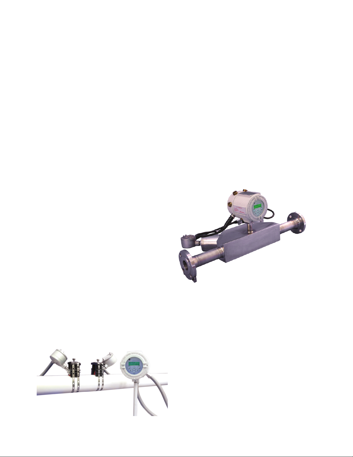
Wetted or Clamp-On Transducers
Ultrasonic fl ow transducers are classifi ed as either wetted
or non-wetted (clamp-on). Clamp-on transducers are
clamped onto the outside of the pipe and never come
into contact with the process fl uid. Wetted transducers
are mounted into the pipe or fl owcell in direct contact
with the process fl uid.
Clamp-on transducers offer maximum convenience,
fl exibility and a low installation cost compared to
traditional fl ow metering technologies. With proper
installation, wetted transducers provide maximum
accuracy (better than 0.5 percent of reading) in most
applications.
The DigitalFlow XMT868i can be used with a variety of
wetted solutions including the PanaFlow™ system. The
PanaFlow meter system relies on the XMT868i as an
integral component to simplify installation. A DigitalFlow
XMT868i is easily mounted to the top of a PanaFlow
system and is shipped ready to install.
Dual-Channel Version Reduces Costs
and Improves Performance
The optional dual-channel/dual-path model can be userconfi gured for a variety of applications. It can be set up
to measure fl ow in two separate pipes with one meter to
reduce the cost-per-measurement point.
To minimize the effects of fl ow profi le distortions, fl ow
swirl and cross fl ow, and for maximum accuracy, you
can install the two sets of transducers on the same pipe.
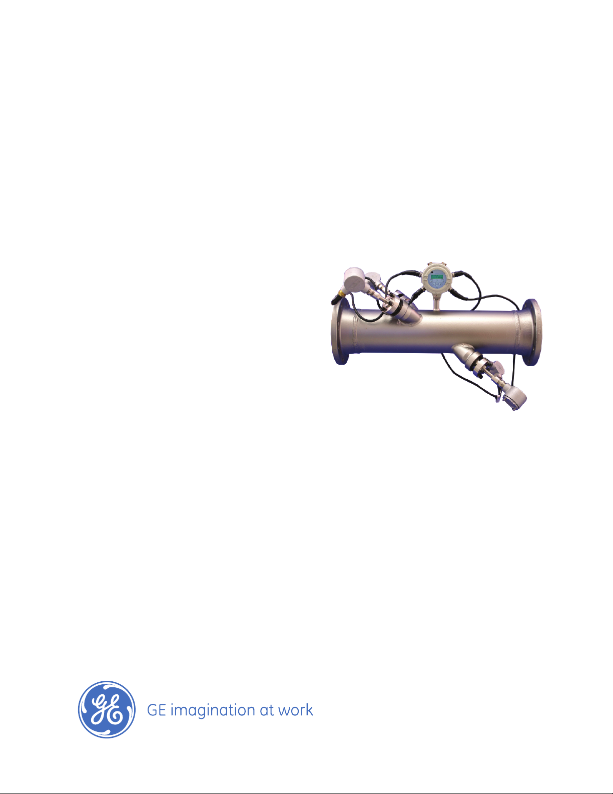
DigitalFlow XMT868i shown with clamp-on transducers
Page 3
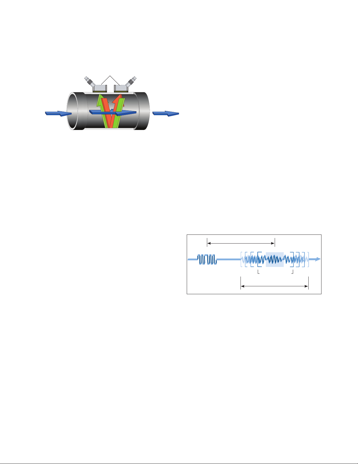
DigitalFlow XMT868i Flow Transmitter
Uses Transit-Time Flow Measurement
Technique
Flowmeter transducers
Fluid
fl ow
Automatically Adjusts to Changing
Fluid Properties
Standard in all DigitalFlow XMT868i transmit ters, our
unique Automatic Tracking Window™ (ATW™) feature
ensures accurate fl ow measurements even when fl uid
properties are unknown or changing. Like the seek mode
on your car stereo, ATW dynamically sweeps the receiver
window whenever the sound speed of the fl uid changes.
This powerful feature lets you measure fl ow when the
fl uid sound speed is unknown, is changing due to large
temperature shifts, or when a new liquid starts to fl ow in
a multiproduct pipeline.
Ultrasonic signal path
Transit-time fl ow measurement technique
In this method, two transducers serve as both ultrasonic
signal generators and receivers. When mounted on a
pipe, they are in acoustic communication with each other,
meaning the second transducer can receive ultrasonic
signals transmitted by the fi rst transducer and vice versa.
In operation, each transducer functions as a transmitter,
generating a certain number of acoustic pulses, and
then as a receiver for an identical number of pulses.
The time interval between transmission and reception
of the ultrasonic signals is measured in both directions.
When the liquid in the pipe is not fl owing, the transit-time
downstream equals the transit-time upstream. When the
liquid is fl owing, the transit-time downstream is less than
the transit-time upstream.
The difference between the downstream and upstream
transit times is proportional to the velocity of the fl owing
liquid, and its sign indicates the direction of fl ow.
ATW works for both clamp-on and wetted transducer
applications by searching for a reliable ultrasonic
receive signal. It does this by varying the time between
the transmit signal and the receive signal window until
the receive signal is found. The tracking window automatically sweeps through a range of time intervals based
on the minimum and maximum expected sound speeds
programmed by the user.
The window moves (tracks) in response to changes in the
fl uid sound speed. Once the optimal signal is found, ATW
locks onto it until another large change in sound speed
occurs. When this happens, ATW returns to the seek
mode until the optimal signal is found again.
Variable time interval
Receive signalTransmit signal
Tracking window
locked onto
receive signal
Range of tracking window
ATW ensures accuracy when fl uid conditions change
Time
Page 4

XMT868i Specifi cations
Electronics
Operation and Performance
Fluid Types
Acoustically conductive fl uids, including most clean
liquids, and many liquids with entrained solids or gas
bubbles. Maximum void fraction depends on transducer,
interrogation carrier frequency, path length and pipe
confi guration.
Pipe Sizes
• Clamp-on transducers: 0.5 in to 300 in (12.7 mm to 7.6
m) and larger
• Wetted transducers: 1 in to 200 in (25.4 mm to 5 m)
and larger
Pipe Wall Thickness
Up to 3 in (76.2 mm)
Pipe Materials
All metals and most plastics. Consult GE for concrete,
composite materials, and highly corroded or lined pipes.
Flow Accuracy (Velocity)
±0.5% of reading (achievable with process calibration)
Typical Clamp-On Flow Accuracy (Velocity)
• Pipe ID>6 in (150 mm): ±1% to 2% of reading
• Pipe ID<6 in (150 mm): ±2% to 5% of reading
Typical Wetted Flow Accuracy (Velocity)
±1% of reading
Accuracy depends on pipe size, installation and whether
measurement is one-path or two-path.
Repeatability
±0.1% to 0.3% of reading
Range (Bidirectional)
–40 to 40 ft/s (–12.2 to 12.2 m/s)
Rangeability (Overall)
400:1
Flow Measurement
Patented Correlation Transit-Time™ mode
Enclosures
• Standard: Epoxy-coated aluminum weatherproof
Type 4X/IP66 Class I, Divison 1, Groups B, C & D; Class
II, Groups E, F & G; Class III Flameproof II 2 GD EEx d IIC
T5/T6
• Optional: Stainless steel
Dimensions
Standard: Weight 10 lb (4.5 kg), size (h x d) 8.2 in x 6.6 in
(208 mm x 168 mm)
Channels
• Standard: One channel
• Optional: Two channels (for two pipes or two-path
averaging)
Display
Optional: two-line x 16-character backlit LCD display,
confi gurable to display up to four measurement
parameters in sequence
Keypad
Built-in infrared, six-button keypad, for full functionality
operation
Power Supplies
• Standard: 100-240 VAC ±10%
• Optional: 12 to 28 VDC, ± 5%
Note: For DC-powered meters, Class 2 rated supplies must
be used for the line power
Power Consumption
20W maximum
Operating Temperature
-40°F to 140°F (-40°C to +60°C)
Storage Temperature
–67°F to 167°F (–55°C to 75°C)
Specifi cations assume a fully developed fl ow profi le
(typically 10 diameters upstream and 5 diameters
downstream of straight pipe run) and fl ow velocity
greater than 1 ft/s (0.3 m/s).
Measurement Parameters
Volumetric fl ow, totalized fl ow and fl ow velocity
Page 5

Standard Inputs/Outputs
Two 0/4 to 20 mA isolated outputs, 600 S maximum load
Namur NE043 compliant
Optional Inputs/Outputs
All analog and digital I/O are available in specifi c
combinations. Consult GE for available option cards.
• Two additional 0/4 to 20 mA isolated outputs, 1000
maximum load
• Two 4 to 20 mA isolated inputs, 24-VDC loop power
• Two or four isolated, three-wire RTD (temperature)
inputs, –148°F to 662°F (–100°C to 350°C), 100 S
platinum
• Two or four pulse or frequency outputs, optically
isolated, 3A maximum, 100 VDC maximum, 1W
maximum, from DC to 10 kHz maximum
• Alarm relays
Digital Interfaces
• Standard: RS232
• Optional: RS485 (multiuser)
• Optional: HART
• Optional: Modbus
• Optional: Foundation Fieldbus
• Optional: OPC server
• Optional: Ethernet
®
protocol
®
protocol
®
Data Logging
• Standard: None
• Optional: Memory capacity (linear and/or circular type)
to log up to 150,000 fl ow data points
Wetted Ultrasonic Flow Transducers
Temperature Ranges
• Standard: –40°F to 212°F (–40°C to 100°C)
• Optional (overall range): –310°F to 1112°F (–190°C to
600°C)
Pressure Ranges
• Standard: 0 to 3000 psig (1 to 207 bar)
• Optional: Higher pressures on request
Materials
• Standard: Stainless steel
• Optional (for Pan-Adapta
Titanium, Hastelloy
PVDF and others
Pan-Adapta plugs allow installation and removal of
wetted transducers without interrupting the process or
emptying the pipe.
Temperature Ranges
• Standard: –40°F to 212°F (–40°C to 100°C)
• Optional (overall range): –310°F to 1112°F (-190°C to
600°C)
Pressure Ranges
• Standard: 0 psig to 3000 psig (1 bar to 207 bar)
• Optional: Higher pressures on request
®
Plugs):
®
alloy, Monel® alloy, duplex, CPVC,
European Compliance
System complies with EMC Directive 89/336/EEC, 73/23/
EEC LVD (Installation Category II, Pollution Degree 2) and
transducers comply with PED 97/23/EC for DN<25
Clamp-On Ultrasonic Flow Transducers
Temperature Ranges
• Standard: -40°F to 302°F (-40°C to 150°C)
• Optional: -328°F to 752°F (-200°C to 400°C)
See specifi c transducer for exact temperature range.
Mountings
Stainless steel chain or strap, welded or magnetic
clamping fi xtures
Area Classifi cations
• Standard: General purpose
• Optional: Weatherproof Type 4X/IP66
• Optional: Explosion Proof, Class I, Division 1, Groups B, C
& D; Class II, Groups E, F & G; Class III
• Optional: Flameproof II 2 G EEx md IIC T6–T3
• Optional: Submersible
Materials
• Standard: Stainless steel
• Optional (for Pan-Adapta
Titanium, Hastelloy
PVDF and others
Pan-Adapta plugs allow installation and removal of
wetted transducers without interrupting the process or
emptying the pipe.
®
Plugs):
®
alloy, Monel® alloy, duplex, CPVC,
Process Connections
• Standard: 1 in or 3/8 in NPTM
• Optional: RF fl anged, socket weld, fuse bond and others
Mountings
Flanged fl owcell, hot tap or cold tap
Area Classifi cations
• Standard: General purpose
• Optional: Weatherproof Type 4/IP65
• Optional: Class I, Division 1, Groups B, C & D; Class II,
Groups E, F & G; Class III
• Optional: Flameproof II 2 G EEx d IIC T6
• Optional: Submersible
Page 6

Transducer Cables
• Standard: One pair of coaxial cables, type RG62 AU, or
as specifi ed for transducer type
• Optional: Lengths up to 1000 ft (330 m) maximum
High-Temperature and High-Pressure
Ultrasonic Flow Transducers
Bundle Waveguide Technology™ System transducer and
holder (see BWT™ System specifi cations)
Clamp-on extended temperature (C-ET) range transducer
system
Energy Measurement
Calculates energy fl ow rate and totalized energy.
Requires optional RTD or analog I/O board.
Temperature Transducers
Loop-powered, three-wire, platinum RTDs; clamp-on and
wetted (thermo-well) types are available
Accuracy
±0.15°C with wetted RTDs (matched pairs)
Range
-4°F to 500°F (-20C° to 260°C)
The accuracy of the energy measurement is a
combination of the accuracy of the associated fl ow
and temperature measurements. 1% to 2% of reading
is typical for calibrated systems. Not all extremes of
parameters can be achieved simultaneously.
Additional Options
PanaView™ PC Interface Software
The DigitalFlow XMT868i communicates with a PC
through a serial interface and Windows
systems. Consult the manual for details on sites, logs and
other operations with a PC.
®
operating
Page 7

XMT868i Application Notes
Additional Options
in Brief
Ultrasonic Flowmeter Saves Money Over Mag
Meter
A sewerage/wastewater facility found that installing a
GE clamp-on ultrasonic fl owmeter offered excellent
performance and accuracy and was far less expensive
than installing a new mag meter. When comparing cost
of a new 30 in (750 mm) mag meter to be installed on
their cast iron line to that of a two-path GE meter, the
water treatment plant decided that the ultrasonic meter
was a bargain. The 30 in (750 mm) mag required the line
to be shut down for installation and major piping work
needed to be done. It was estimated that it would take
several days to get the meter running. The GE meter was
easily installed to existing piping without ever shutting
down the pipe and installation was complete within a
day.
PanaView™ PC Interface Software
The DigitalFlow XMT868i communicates with a PC
through a serial interface and Windows
systems. Consult the manual for details on sites, logs and
other operations with a PC.
®
operating
710°F (376°C) Resid Line? No Problem.
With the DigitalFlow XMT868i combined with the Bundle
Wafeguide Technology System from GE, you can
measure cryogenic fl uids like LNG or the demanding
temperatures of coker resid lines that can run hotter
than 700°F (371°C). Ultrasonic fl owmeters will not cause
pressure drop and have no impulse lines to plug, making
them a great solution for diffi cult fl uids.
Even though most ultrasonic manufacturers’ fl owmeters
can only handle up to 500°F (260°C), GE’s BWT systems
have been able to reach up to 1000°F (537°C). The unique
design removes the piezoelectric element from the
extreme temperatures by using wave guide technology.
The transducer can even be swapped out under
operating conditions. One customer has installed 16
units, replacing their wedge meters, and has had them
operating maintenance free for more than fi ve years.
Accuracy
±0.15°C with wetted RTDs (matched pairs)
Range
–4°F to 500°F (–20C° to 260°C)
The accuracy of the energy measurement is a
combination of the accuracy of the associated fl ow
and temperature measurements. 1% to 2% of reading
is typical for calibrated systems. Not all extremes of
parameters can be achieved simultaneously.
Bundle Waveguide Technology System
Page 8

www.gemeasurement.com
920-170E
© 2016 General Electric Company. All Rights Reserved. Specifi cations are subject to change without notice. GE is a registered trademark of General Electric Company. Other company or product
names mentioned in this document may be trademarks or registered trademarks of their respective companies, which are not affi liated with GE.
 Loading...