

Page 1

GE
Measurement & Control Solutions Flow
Model T9
Ultrasonic Flow Transducer
Installation Guide
916-080 Rev. B
July 2010
Page 2

Page 3

Model T9
Ultrasonic Flow Transducer
Installation Guide
916-080 Rev. B
July 2010
GESensingInspection.com
©2010 General Electric Company. All rights reserved.
Technical content subject to change without notice.
Page 4

[no content intended for this page]
ii
Page 5

Contents
Chapter 1. Information
1.1 Overview. . . . . . . . . . . . . . . . . . . . . . . . . . . . . . . . . . . . . . . . . . . . . . . . . . . . . . . . . . . . . . . . . . . . . . . . . . . . . . . . . . . . . . . . . . . . . . . 1
1.2 Transducer Construction. . . . . . . . . . . . . . . . . . . . . . . . . . . . . . . . . . . . . . . . . . . . . . . . . . . . . . . . . . . . . . . . . . . . . . . . . . . . . . . .1
Chapter 2. Installing Pipe Nozzles
2.1 Introduction. . . . . . . . . . . . . . . . . . . . . . . . . . . . . . . . . . . . . . . . . . . . . . . . . . . . . . . . . . . . . . . . . . . . . . . . . . . . . . . . . . . . . . . . . . . .3
2.2 Identifying and Checking the Nozzle Installation Kit Components . . . . . . . . . . . . . . . . . . . . . . . . . . . . . . . . . . . . . . . . .4
2.3 Selecting and Marking the First Nozzle Location. . . . . . . . . . . . . . . . . . . . . . . . . . . . . . . . . . . . . . . . . . . . . . . . . . . . . . . . . . 5
2.4 Determining and Marking the Second Nozzle Location . . . . . . . . . . . . . . . . . . . . . . . . . . . . . . . . . . . . . . . . . . . . . . . . . . .7
2.5 Installing the First Welding Boss. . . . . . . . . . . . . . . . . . . . . . . . . . . . . . . . . . . . . . . . . . . . . . . . . . . . . . . . . . . . . . . . . . . . . . . .10
2.6 Installing the First Nozzle . . . . . . . . . . . . . . . . . . . . . . . . . . . . . . . . . . . . . . . . . . . . . . . . . . . . . . . . . . . . . . . . . . . . . . . . . . . . . .12
2.7 Installing the Second Welding Boss and Nozzle . . . . . . . . . . . . . . . . . . . . . . . . . . . . . . . . . . . . . . . . . . . . . . . . . . . . . . . . .14
2.8 Hot Tapping the Pipe . . . . . . . . . . . . . . . . . . . . . . . . . . . . . . . . . . . . . . . . . . . . . . . . . . . . . . . . . . . . . . . . . . . . . . . . . . . . . . . . . .14
Chapter 3. Inserting T9 Transducers into the Pipe
3.1 Introduction. . . . . . . . . . . . . . . . . . . . . . . . . . . . . . . . . . . . . . . . . . . . . . . . . . . . . . . . . . . . . . . . . . . . . . . . . . . . . . . . . . . . . . . . . . .15
3.2 Inserting Transducers with the Simple Holder . . . . . . . . . . . . . . . . . . . . . . . . . . . . . . . . . . . . . . . . . . . . . . . . . . . . . . . . . . .15
3.3 Inserting Transducers with the Barrel Holder. . . . . . . . . . . . . . . . . . . . . . . . . . . . . . . . . . . . . . . . . . . . . . . . . . . . . . . . . . . .19
3.4 Inserting Transducers with the Flanged Holder. . . . . . . . . . . . . . . . . . . . . . . . . . . . . . . . . . . . . . . . . . . . . . . . . . . . . . . . . .22
3.4.1 Securing the Transducers. . . . . . . . . . . . . . . . . . . . . . . . . . . . . . . . . . . . . . . . . . . . . . . . . . . . . . . . . . . . . . . . . . . . . . . . .25
Chapter 4. Maintenance
4.1 Introduction. . . . . . . . . . . . . . . . . . . . . . . . . . . . . . . . . . . . . . . . . . . . . . . . . . . . . . . . . . . . . . . . . . . . . . . . . . . . . . . . . . . . . . . . . . .27
4.2 Removing Transducers . . . . . . . . . . . . . . . . . . . . . . . . . . . . . . . . . . . . . . . . . . . . . . . . . . . . . . . . . . . . . . . . . . . . . . . . . . . . . . . .27
Chapter 5. T9 Specifications
5.1 Specifications . . . . . . . . . . . . . . . . . . . . . . . . . . . . . . . . . . . . . . . . . . . . . . . . . . . . . . . . . . . . . . . . . . . . . . . . . . . . . . . . . . . . . . . . .31
Model T9 Ultrasonic Flow Transducer Installation Guide iii
Page 6

Contents
[no content intended for this page]
iv Model T9 Ultrasonic Flow Transducer Installation Guide
Page 7

Preface
Information Paragraphs
Note paragraphs provide information that provides a deeper understanding of the situation, but is not essential to
•
the proper completion of the instructions.
• Important paragraphs provide information that emphasizes instructions that are essential to proper setup of the
equipment. Failure to follow these instructions carefully may cause unreliable performance.
• Caution! paragraphs provide information that alerts the operator to a hazardous situation that can cause damage to
property or equipment.
• Warning! paragraphs provide information that alerts the operator to a hazardous situation that can cause injury to
personnel. Cautionary information is also included, when applicable.
Safety Issues
WARNING! It is the responsibility of the user to make sure all local, county, state and national codes,
regulations, rules and laws related to safety and safe operating conditions are met for each
installation.
Auxiliary Equipment
Local Safety Standards
The user must make sure that he operates all auxiliary equipment in accordance with local codes, standards,
regulations, or laws applicable to safety.
Working Area
WARNING! Auxiliary equipment may have both manual and automatic modes of operation. As equipment
can move suddenly and without warning, do not enter the work cell of this equipment during
automatic operation, and do not enter the work envelope of this equipment during manual
operation. If you do, serious injury can result.
WARNING! Make sure that power to the auxiliary equipment is turned OFF and locked out before you
perform maintenance procedures on the equipment.
Qualification of Personnel
Make sure that all personnel have manufacturer-approved training applicable to the auxiliary equipment.
Personal Safety Equipment
Make sure that operators and maintenance personnel have all safety equipment applicable to the auxiliary equipment.
Examples include safety glasses, protective headgear, safety shoes, etc.
Unauthorized Operation
Make sure that unauthorized personnel cannot gain access to the operation of the equipment.
Model T9 Ultrasonic Flow Transducer Installation Guide v
Page 8
Preface
Environmental Compliance
Waste Electrical and Electronic Equipment (WEEE) Directive
GE Measurement & Control Solutions is an active participant in Europe’s Waste Electrical and Electronic Equipment
(WEEE) take-back initiative, directive 2002/96/EC.
The equipment that you bought has required the extraction and use of natural resources for its production. It may
contain hazardous substances that could impact health and the environment.
In order to avoid the dissemination of those substances in our environment and to diminish the pressure on the natural
resources, we encourage you to use the appropriate take-back systems. Those systems will reuse or recycle most of the
materials of your end life equipment in a sound way.
The crossed-out wheeled bin symbol invites you to use those systems.
If you need more information on the collection, reuse and recycling systems, please contact your local or regional
waste administration.
Visit http://www.gesensing.com/environment/weee.htm
this initiative.
for take-back instructions and more information about
vi Model T9 Ultrasonic Flow Transducer Installation Guide
Page 9
Chapter 1. Information
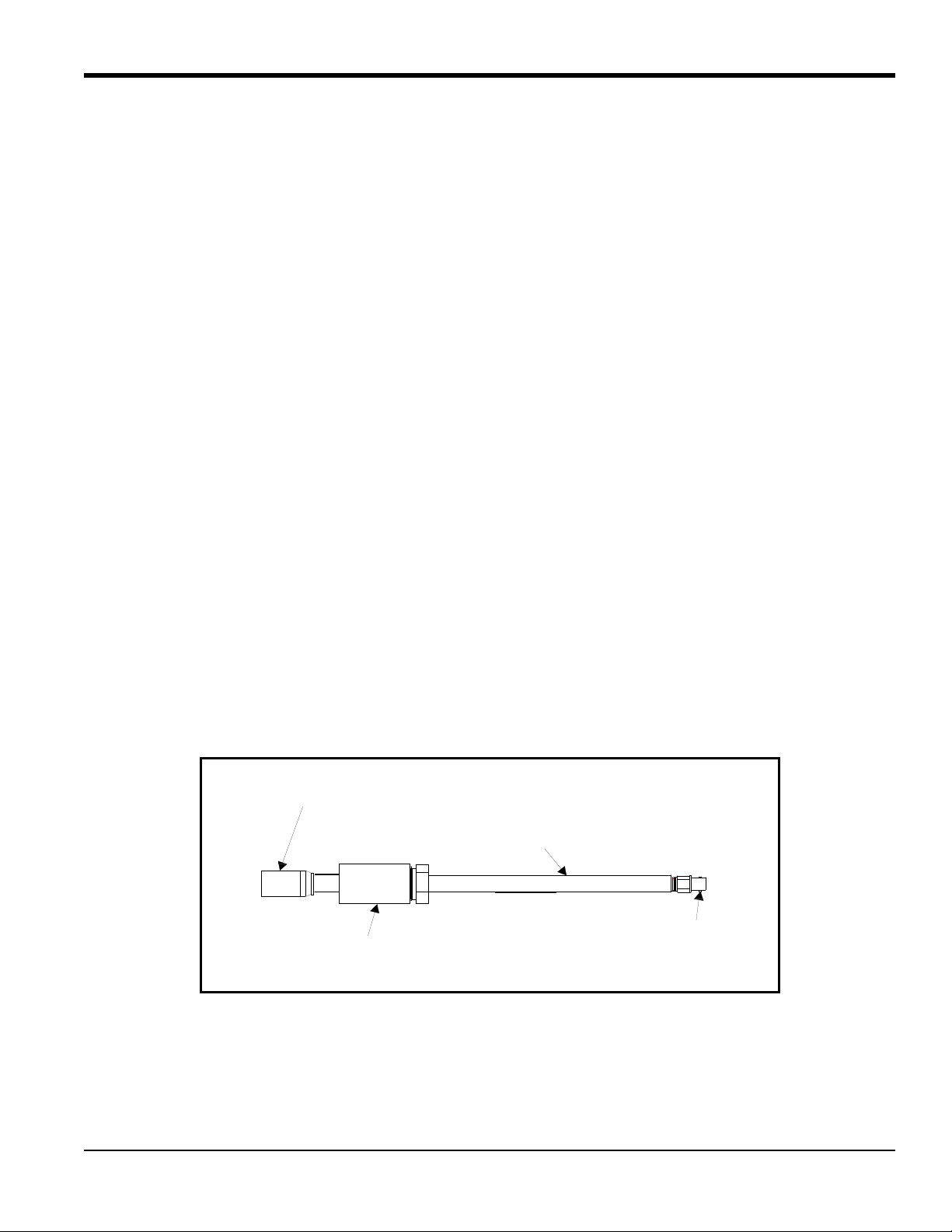
Metallic Body
Transducer Head
BNC Connector
Optional Noise Dampening Fitting
Chapter 1. Information
1.1 Overview
The T9 ultrasonic flow transducer is used exclusively with the GE line of ultrasonic flowmeters. These transducers
measure the flow rate of saturated steam and most gases through pipes having diameters between 2 in. (50 mm) and 48
in. (1200 mm). Such measurements are independent of the pipe material. This document provides details on the
following topics:
• Transducer Construction
• Nozzle Installation
• Transducer Installation
• Maintenance
• Specifications
1.2 Transducer Construction
Each T9 transducer assembly (see Figure 1) consists of the following components:
• a metallic body
• a transducer head that consists of a piezoelectric element wired to the BNC connector
• a BNC style connector for use in connecting the transducer to the flowmeter
• an optional noise dampening fitting improves transducer signal transmission.
o
The T9 transducer has a 180
(40 cm).
head and is available in the following lengths: 11 in. (28 cm), 13 in. (33 cm) and 16 in.
Figure 1: General T9 Transducer
Model T9 Ultrasonic Flow Transducer Installation Guide 1
Page 10

Chapter 1. Information
[no content intended for this page]
2 Model T9 Ultrasonic Flow Transducer Installation Guide
Page 11

Chapter 2. Installing Pipe Nozzles
Chapter 2. Installing Pipe Nozzles
2.1 Introduction
Before the T9 transducers can be installed into the pipe, you will need to install pipe nozzles. Nozzles can be installed
on a hot or cold pipe using a GE Nozzle Installation Kit. Nozzles are installed in a Tilted 45
IMPORTANT: This procedure only applies if you ar e usin g a Nozzle Installation Kit. If you are tapping the pipe without
using a Nozzle Installation Kit, refer to the supplied drawings in your shipment. This procedure is written
and illustrated for installations on horizontal pipes; however, the procedure is the same for vertical pipe
installations.
This procedure contains the following instructions:
• Identifying and Checking the Nozzle Installation Kit Components
• Selecting and Marking the First Nozzle Location
• Determining and Marking the Second Nozzle Location
o
configuration.
• Installing the First Welding Boss
• Installing the First Nozzle
• Installing the Second Welding Boss and Nozzle
• Hot Tapping the Pipe
Model T9 Ultrasonic Flow Transducer Installation Guide 3
Page 12
Chapter 2. Installing Pipe Nozzles
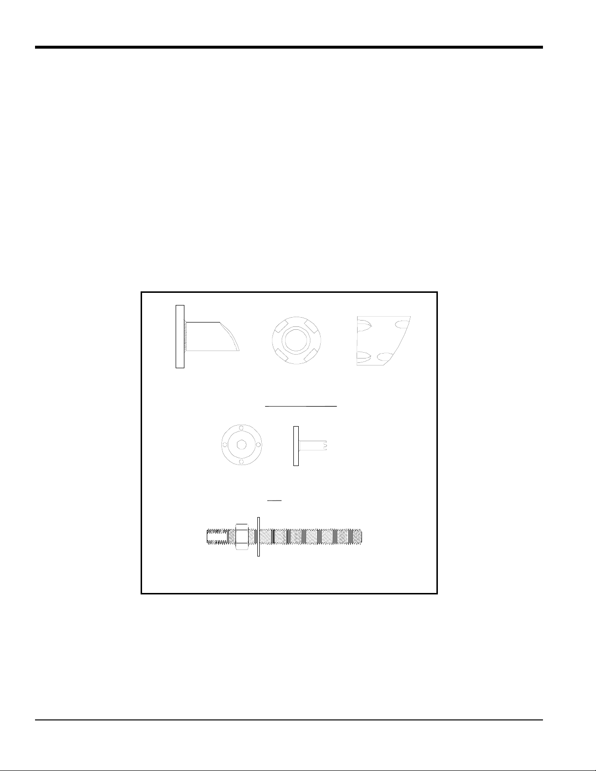
Nozzle
Top
Welding Boss
Side
Top
Jig
Side
Threaded Rod with Washer and Nut
2.2 Identifying and Checking the Nozzle Installation Kit Components
The nozzle kit consists of various components which you must identify and check as described in the following
sub-sections.
The Nozzle Installation Kit contains the materials listed below. Use Figure 2 to help identify each component.
• 2 Nozzles
• 2 Welding Bosses
• 1 Jig
• 1 Threaded Rod (1 in. diameter), washer and nut
IMPORTANT: You will need to supply eight
5
/8 in. 4.25 in. studs with two nuts each.
Figure 2: Components for Nozzle Installation Kit
4 Model T9 Ultrasonic Flow Transducer Installation Guide
Page 13
Chapter 2. Installing Pipe Nozzles
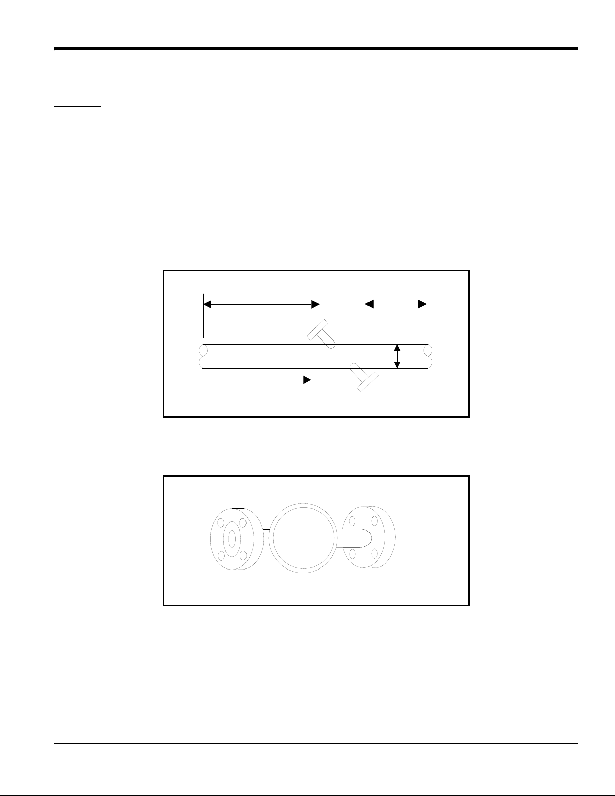
10D
5D
D
Flow
End View
2.3 Selecting and Marking the First Nozzle Location
CAUTION! Correct nozzle alignment is critical to the successful operation of the flowmeter; therefore, all
marking, positioning and welding operations must be carried out with the utmost attention to
accuracy. Unless otherwise stated, dimensional positioning of the nozzles must be held to a
tolerance of 1/16 in. (1.6 mm) relative to each other and with respect to the pipe centerline. the
angular tolerance must be held to 1
All hole cutting in process piping must be performed using hot tapping equipment.
1. For optimum performance, you should select a location that has undisturbed straight run pipeline at least 10 pipe
diameters upstream and 5 pipe diameters downstream from the point of measurement. Undisturbed pipe means
avoiding sources of turbulence such as valves, flanges, elbows; avoiding swirl; and avoiding disturbed flow
profiles.
O
.
2. We recommend that you install the nozzles on a diameter as near as possible to the horizontal plane (i.e., 3 o’clock
and 9 o’clock) as shown below.
Model T9 Ultrasonic Flow Transducer Installation Guide 5
Page 14
Chapter 2. Installing Pipe Nozzles
Side View
Side View
2.3 Selecting and Marking the First Nozzle Location (cont.)
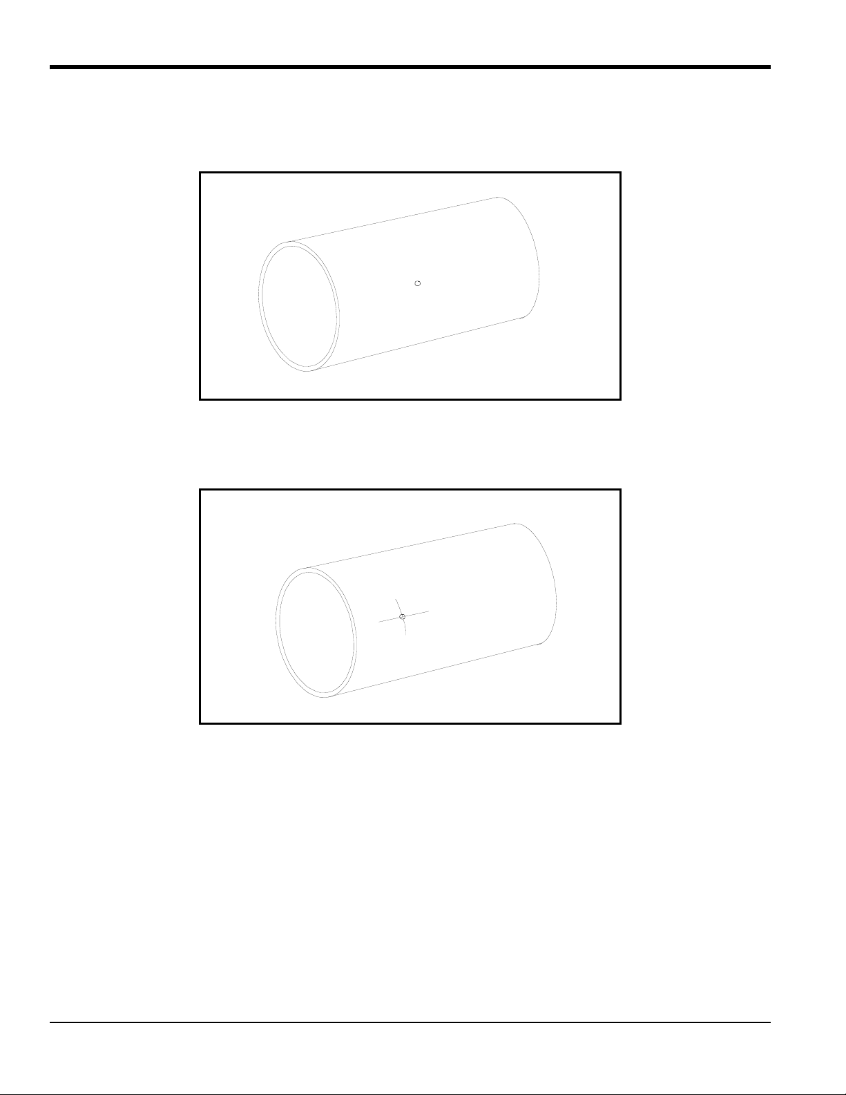
3. At the 3 o’clock position, center punch the pipe to mark the position for the center of the first nozzle.
4. Spray this area with a marking dye product. Using a metal edge, scribe a vertical and a horizontal line (6 in. long)
that intersect at the center punch mark.
6 Model T9 Ultrasonic Flow Transducer Installation Guide
Page 15

Chapter 2. Installing Pipe Nozzles
D1
D2
D3
D4
Side View
Average
O.D.
4 X O.D.
2.4 Determining and Marking the Second Nozzle Location
1. The position for the second nozzle is a distance equal to one pipe diameter along the pipe and loc ated on the
opposite side of the pipe (i.e., 180
2. Due to the possible variation in outside diameter of the pipe, measure the outside diameter of the pipe at four
locations between the nozzle centers. Calculate the average outside diameter based on these measurements.
°
around). Spray this area with a marking dye product.
3. Using a roll of polyester film (or equivalent), cut a strip of film at the width and length as follows:
IMPORTANT: Ensure that the sides of the film are cut parallel to each other.
• Width - equal to the average outside diameter calculated in Step 1 above.
• Length - equal to 4 times the outside diameter of the pipe.
Model T9 Ultrasonic Flow Transducer Installation Guide 7
Page 16

Chapter 2. Installing Pipe Nozzles
Side View
Overlap Mark
Overlap Mark Fold to Here
Mark the Edge
2.4 Determining and Marking the Second Nozzle Location (cont.)
4. Wrap the strip of film around the pipe with one edge running along the vertical scribe line at the first nozzle
location. Make sure the strip overlaps squarely
equals the circumference of the pipe.
around the pipe and mark the overlap position of the strip. This
5. Remove the strip of film and fold it as shown below to determine the position which is diametrically opposite the
overlap position when the film is reapplied to the pipe.
6. Mark the outside of the fold for reference.
8 Model T9 Ultrasonic Flow Transducer Installation Guide
Page 17

Chapter 2. Installing Pipe Nozzles
Fold Mark
Side View
Punch Here
Side View
Scribe Lines
Side View
2.4 Determining and Marking the Second Nozzle Location (cont.)
7. Place the strip of film on the pipe again; this time, line up the overlap mark with the horizontal and vertical scribe
lines. Again, make sure you wrap the strip of film squarely around the pipe.
8. The new position of the center of the second nozzle is now identified as the intersection of the fold line and the
second edge of the strip of film. Center punch this location prior to removing the strip of film.
9. Remove the film.
10. Scribe vertical and horizontal lines (each 6 in. long) to intersect at the center-punch mark.
Model T9 Ultrasonic Flow Transducer Installation Guide 9
Page 18

Chapter 2. Installing Pipe Nozzles
XD2
d2
sin1–dDtan
-------------------------------------------–=
True Center Line
Oblique Center Line
Side View
2.5 Installing the First Welding Boss
1. Before welding the first boss, you must add another scribe line known as the oblique center line. The oblique center
line compensates for the slope or oblique of the boss. The oblique center line is offset from the true center (vertical)
scribe line marked earlier by a distance of “X,” which is dependent on the pipe outside diameter as follows:
where:
D = pipe outside diameter
d = welding boss outside diameter, 1.660 in. (4 cm)
Table 1 below shows values of X for various pipe sizes.
Table 1: X Values for Various Pipe Sizes
Pipe
X DimensionsNPS (DN) O.D.
6 in. (150 mm) 6.625 in. (17 cm) 0.106 in. (2.69 mm)
8 in. (200 mm) 8.625 in. (22 cm) 0.081 in. (2.06 mm)
10 in. (250 mm) 10.75 in. (27 cm) 0.064 in. (1.62 mm)
12 in. (300 mm) 12.75 in. (32 cm) 0.054 in. (1.37 mm)
14 in. (350 mm) 14.00 in. (35.5 cm) 0.049 in. (1.24 mm)
2. Scribe the oblique center line on the pipe at the prescribed distance from the true center line. The oblique center
line should be marked on the side of the true center line that is closer to the second nozzle location.
10 Model T9 Ultrasonic Flow Transducer Installation Guide
Page 19

Chapter 2. Installing Pipe Nozzles
Oblique Center Line
Top View
Side View
Scribe Mark
2.5 Installing the First Welding Boss (cont.)
3. Position the welding boss such that the four scribe lines on the welding boss are lined up with the horizontal scribe
mark and the oblique center line on the pipe. Make sure you orient the boss as shown below.
4. Clamp the boss in place using a pipe strap or equivalent so that it cannot move during tack welding.
5. Check the boss alignment, then tack weld the carbon steel boss to the pipe in each of the four grooves between the
boss scribe marks.
6. Remove the clamp and check the alignment again. If the boss is misaligned by 0.02 in. (0.5 mm) or more, remove
the boss, grind off the welds and reinstall.
Model T9 Ultrasonic Flow Transducer Installation Guide 11
Page 20

Chapter 2. Installing Pipe Nozzles
Threaded Rod
Welded Boss
Jig
Nozzle
Studs &
Sets of Nuts
2.6 Installing the First Nozzle
IMPORTANT: It is essential that the nozzle is set up and fixed in position using the jig and 1-in. threaded rod provided,
prior to welding the nozzle.
1. Screw the threaded rod into boss that is welded onto the pipe. If necessary, remove the washer and nut from the
threaded rod.
2. Insert the pipe section of the jig into the pipe section of the nozzle and fasten using four studs and eight nuts (not
supplied).
12 Model T9 Ultrasonic Flow Transducer Installation Guide
Page 21

Chapter 2. Installing Pipe Nozzles
Jig/Nozzle Assembly
Threaded Rod
Welded Boss
Washer and Nut
2.6 Installing the First Nozzle (cont.)
3. Slide the jig/nozzle assembly over the threaded rod, fitting the jig into the welding boss while aligning the
contoured end of the nozzle so it matches the pipe arc.
4. Align the nozzle scribe marks with the pipe scribe marks and tighten the assembly in place, using the washer and
nut.
Model T9 Ultrasonic Flow Transducer Installation Guide 13
Page 22

Chapter 2. Installing Pipe Nozzles
Flow
2.6 Installing the First Nozzle (cont.)
5. The jig, boss, and nozzle combination is designed to provide a 0.094 in. (2.4 mm) root gap between the beveled
edge of the nozzle and the outside diameter of the pipe. If the 0.094 in.
(2.4 mm) clearance does not exist all around, the nozzle must be removed and ground appropriately to provide the
required clearance. If the root gap is larger than the 0.094 in. (2.4 mm) dimension, then suitably sized wa shers ma y
be inserted between the jig and the nozzle in order to reduce the root gap dimension.
WARNING!
6. Tack weld the nozzle to the pipe at four diametrically opposed points, each tack being approximately 0.6 in. (15
mm) in length. Allow to cool for 30 seconds between tacks.
7. Proceed to complete the root pass and subsequent filler passes as required.
8. Allow to cool, then remove the threaded rod, washer, nut, and jig.
ONLY QUALIFIED PERSONNEL SHOULD WELD BOSSES AND NOZZLES, USING A SUITABLE ASME IX
QUALIFIED WELDING PROCEDURE.
2.7 Installing the Second Welding Boss and Nozzle
Install the second welding boss and nozzle at the required position as described in Installing the First Welding Boss and
Installing the First Nozzle beginning on page 10. The completed installation should appear as shown below.
2.8 Hot Tapping the Pipe
WARNING! HOT TAPPING SHOULD BE PERFORMED ONLY BY QUALIFIED PERSONNEL. FOLLOW ALL
APPLICABLE CODE AND SAFETY PRACTICES DURING THESE PROCEDURES.
1. Install 3 in. ANSI flanged full-bore isolation valves on both nozzles (8 in. face-to-face for 150#RF or 11.125 in. for
300#RF) with gasket and 5/8-in. diameter studs and nuts. Orient valve ha ndles to minimize interference.
2. Hot tap holes in the pipe using hot tap machine equipped with a 3/4 in. (19 mm) drill bit. Then use a coupon
retaining hole saw to cut a hole a minimum diameter of 2.36 in. (60 mm).
14 Model T9 Ultrasonic Flow Transducer Installation Guide
Page 23

Chapter 3. Inserting T9 Transducers into the Pipe
Z Dimension
Chapter 3. Inserting T9 Transducers into the Pipe
3.1 Introduction
The T9 transducer is typically installed into a meter body. The meter body is a section of pipe that contains the ports
where the transducers will be mounted. The meter body may be prefabricated or created by installing ports on the
existing pipe. The T9 can be inserted into the pipes using a number of methods:
• Simple Holder
• Barrel Holder
• Flanged Holder
3.2 Inserting Transducers with the Simple Holder
The simple holder consists of a flange with a compression fitting tapped or welded in the middle of the flange.
o
Transducers are usually installed in a diagonal 45
The procedure below applies to a diagonal 45
not exceed the pipe inside diameter. Consult GE for other configurations.
configuration, although other configurations are available.
o
single-traverse configuration when the transducer insertion depth does
IMPORTANT: If you do not know the transducer insertion depth, measure the length of the nozzle (from the top of the
nozzle to the pipe) and then add the pipe ID to that measurement. If this measurement equals the Z
dimension, then the transducer insertion depth does not exceed the pipe ID.
Use the steps below to insert the simple holder.
1. Measure the Z dimension as shown below. The Z dimension is set at the factory and should be verified.
Model T9 Ultrasonic Flow Transducer Installation Guide 15
Page 24

Chapter 3. Inserting T9 Transducers into the Pipe
Transducer Head
Nozzle
Gasket
Pipe
Pipe
Nut
Washer
Nozzle
Washer
Bolt
3.2 Inserting Transducers with the Simple Holder (cont.)
2. Insert the holder into the pipe nozzle. Place a spiral-wound gasket between the nozzle and the holder. The nozzle
length determines the transducer face position.
3. Bolt the holder flange onto the nozzle flange as shown below.
16 Model T9 Ultrasonic Flow Transducer Installation Guide
Page 25

Chapter 3. Inserting T9 Transducers into the Pipe
Junction Box
Compression Fitting
45°
C
L
3.2 Inserting Transducers with the Simple Holder (cont.)
4. Install the junction box on the end of the transducer using the compression fitting.
5. Repeat the above steps for the other transducer. The figure below shows a completed installation.
Model T9 Ultrasonic Flow Transducer Installation Guide 17
Page 26

Chapter 3. Inserting T9 Transducers into the Pipe
L
P
3.2 Inserting Transducers with the Simple Holder (cont.)
6. Use the equation below to calculate the path length (P) based on the pipe inside diameter and transducer face angle:
P = ID/cos (A)
where: ID = pipe inside diameter and
A = nozzle angle
7. Record the axial dimension (L). The L dimension is equal to the pipe inside diameter.
8. Refer to your flowmeter Startup Guide or User’s Manual to make transducer electrical connections.
You have completed transducer installation.
18 Model T9 Ultrasonic Flow Transducer Installation Guide
Page 27

Chapter 3. Inserting T9 Transducers into the Pipe
Stainless Steel Pipe
180 Transducer Head
o
Compression Fitting
(with PTFE)
Carbon Steel Blind Flange
Insertion Depth
(from end of transducer to raised face on flange)
180° Head Transducer
3.3 Inserting Transducers with the Barrel Holder
A barrel holder is a flange with a pipe welded through its center (the flange and pipe size are dependent upon the
application.) The pipe provides support for the transducer. Compression fittings on the top and bottom of the barrel
holder keep the transducer in place. See Figure 3.
Figure 3: Barrel Holder with 180
o
Head Transducer
1. All equipment comes pre-assembled. Measure the insertion depth as shown below. The insertion depth is set at the
factory and should be verified.
Model T9 Ultrasonic Flow Transducer Installation Guide 19
Page 28

Chapter 3. Inserting T9 Transducers into the Pipe
Barrel Holder
Nozzle
Pipe
Gasket
Nozzle
Washer
Nut
Pipe
Bolt
Inserting Transducers with the Barrel Holder (cont.)
Procedure for Inserting Transducers with the Barrel Holder (cont.)
2. Insert the holder into the pipe nozzle. Place a spiral-wound gasket between the nozzle and the holder. The nozzle
length determines the transducer face position.
3. Bolt the holder flange onto the nozzle flange as shown below.
20 Model T9 Ultrasonic Flow Transducer Installation Guide
Page 29

Chapter 3. Inserting T9 Transducers into the Pipe
Compression Fitting
Junction Box
L
P
45°
C
L
3.3 Inserting Transducers with the Barrel Holder (cont.)
4. Install the junction box on the end of the transducer using the compression fitting.
5. Repeat the above steps for the other transducer.
6. Use the equation below to calculate the path length (P) based on the pipe inside diameter and transducer face
angle:
P = ID/cos (A)
where: ID = pipe inside diameter
A = nozzle angle
7. Record the axial dimension (L).
8. Refer to your flowmeter Startup Guide or User’s Manual to make transducer electrical connections.
You have completed transducer installation.
Model T9 Ultrasonic Flow Transducer Installation Guide 21
Page 30

Chapter 3. Inserting T9 Transducers into the Pipe
T9 Transducer
1.5-in. Flange with Hub
Compression
Fitting
PipeWallThickness
Acos
--------------------------------------------------- -
T9 Transducer
Loosen
Compression
Fitting
Transducer Insert ion Depth (TID)
3.4 Inserting Transducers with the Flanged Holder
The flanged holder is constructed of a 1½ in.-300 or 1½ in.-600# flange. The flange has a large hub that supports the
T9 transducer and also provides acoustic isolation. The transducer is inserted through the flange and is held in place by
a 1/2 in. tube compression fitting. See Figure 4.
Use the procedure below to install transducers.
Figure 4: Flanged Holder with T9 Transducer
1. Calculate the transducer insertion depth (TID). To do this measure from the inside diameter of the pipe to the raised
face of the nozzle flange via the centerline. Then add 0.125 in. (3.2 mm) to the measurement. This equals the TID.
If you are not able to measure from the inside of the nozzle, use the following equation:
Transducer Insertion Depth = Nozzle Length + + 0.125 in. (3.2 m) (where A = Nozzle Angle)
2. Set the transducer to the desired depth by loosening the compression fitting and moving the transducer to the
calculated insertion depth.
22 Model T9 Ultrasonic Flow Transducer Installation Guide
Page 31

Chapter 3. Inserting T9 Transducers into the Pipe
Gasket
Gasket
3.4 Inserting Transducers with the Flanged Holder (cont.)
3. Tighten the compression fitting to hold the transducer in place.
4. Place a spiral-wound gasket over the end of the transducer.
Note: You must use a gasket in order to provide the proper acoustic isolation.
5. Inspect the pipe nozzle. Make sure it is free from dirt/rust. Use the steel wool to clean the pipe nozzle if necessary.
6. Insert the transducer into the nozzle.
Model T9 Ultrasonic Flow Transducer Installation Guide 23
Page 32

Chapter 3. Inserting T9 Transducers into the Pipe
Top View
Top View
3.4 Inserting Transducers with the Flanged Holder (cont.)
3.4.1 Securing the Transducers
1. Secure the flanges together by placing the studs, washers and nuts as shown below. Hand-tighten each stud. The
factory recommends using ASTM A193 Grade B7 (or equivalent) studs and ASTM A19 Grade 2H (or equivalent)
nuts.
24 Model T9 Ultrasonic Flow Transducer Installation Guide
Page 33

Chapter 3. Inserting T9 Transducers into the Pipe
1
1
2
2
3
3
4
4
5
6
7
8
Begin Here
4-Hole Flange
8-Hole Flange
1
1
2
2
3
3
4
4
5
6
7
8
Begin Here
4-Hole Flange
8-Hole Flange
3.4.1 Securing the Transducers (cont.)
2. Once all the studs are inserted and hand-tightened, the studs must be torqued to 80 ft-lb (108 N-m) in three stages.
Set the torque wrench to 30 ft-lb (40 N-m) and torque the studs in the order shown below.
3. Set the torque wrench to 60 ft-lb (81 N-m) and torque in the order shown below.
4. Set the torque wrench to 80 ft-lb (108 N-m) and tighten in the order shown above.
5. Repeat steps 1 through 4 for the other nozzle.
Model T9 Ultrasonic Flow Transducer Installation Guide 25
Page 34

Chapter 3. Inserting T9 Transducers into the Pipe
Top View
Compression Fitting
3.4.1 Securing the Transducers (cont.)
6. Install the junction boxes on the end of the transducers using the compression fittings.
7. Refer to your flowmeter Startup Guide or User’s Manual to make transducer electrical connections.
26 Model T9 Ultrasonic Flow Transducer Installation Guide
Page 35

Chapter 4. Maintenance
Chapter 4. Maintenance
4.1 Introduction
Once the transducers are properly installed into the pipe nozzles as described in the previous section, the T9 transducers
require no additional adjustments.
Periodic inspection of the installation to verify the torque on the mounting bolts may be required, if erratic flow rate
measurements are observed.
If you suspect something is wrong with a transducer or need to replace a transducer, use the appropriate removal
procedure that follows.
4.2 Removing Transducers
Use the steps below to remove transducers that have been installed with a simple, barrel or flange holder.
Note: The illustrations in the steps below use a simple holder.
WARNING!
1. Disconnect power from the flowmeter.
WARNING!
2. Shut down or isolate the process line where you will be removing the transducers.
WARNING!
FOLLOW ALL APPLICABLE SAFETY CODES WHILE PERFORMING THE FOLLOWING PROCEDURES.
MAKE SURE POWER IS DISCONNECTED BEFORE PERFORMING THE FOLLOWING STEPS.
SHUT DOWN THE PROCESS LINE BEFORE REMOVING TRANSDUCERS. SERIOUS INJURY MAY
OCCUR IF TRANSDUCERS ARE REMOVED FROM A LIVE PROCESS LINE.
Model T9 Ultrasonic Flow Transducer Installation Guide 27
Page 36

Chapter 4. Maintenance
Junction Box
4.2 Removing Transducers (cont.)
3. Disconnect the transducer cables at the junction box.
28 Model T9 Ultrasonic Flow Transducer Installation Guide
Page 37

Chapter 4. Maintenance
Compression Fitting
4.2 Removing Transducers (cont.)
4. Remove the junction box from the end of the transducer by loosening the compression fitting and unscrewing the
junction box.
Model T9 Ultrasonic Flow Transducer Installation Guide 29
Page 38

Chapter 4. Maintenance
Bolts
Bolts
Gasket
Blind Flange
4.2 Removing Transducer (cont.)
5. Remove the bolts that fasten the simple/barrel/flange holder to the nozzle flange, and remove it from the pipe
nozzle.
[no content intended for this page]
6. Install a new flange gasket on the pipe nozzle. Then, fasten the “blind” flange to the pipe nozzle with the bolts
removed in the previous step.
7. Repeat steps 3 through 6 for the other transducer if necessary.
You have completed the removal procedure, it is now safe to reopen the process line.
30 Model T9 Ultrasonic Flow Transducer Installation Guide
Page 39

Chapter 5. T9 Specifications
5.1 Specifications
Table 2: T9 Transducer Specifications
Transducer T9 Specification
Designation Hazardous area applications; flare gas, hydrocarbon gases, saturated steam.
Installation Type Wetted
Material
Field Mounting Flowcell, hot or cold tap
Process Connection 1.5 in. (40 mm) flanged
Holder Type Simple, barrel or flanged holder
Holder Ratings 150#, 300#, 600#
Operating Frequency 100 kHz
Pressure Range 0 to 2700 psig
Electrical Rating 200 V peak-to-peak, 5 mA
Ambient Temperature Range
Process Temperature Range
Standard: Titanium
Optional: 316SS, Monel
Europe: -40 to +158°F (-40 to +70°C)
North America: -4 to +140°F (-20 to +60°C)
Normal Temperature: -58 to +302°F (-50 to +150°C)
High Temperature: -58 to +500°F (-50 to +260°C)
or Hastelloy
Chapter 5. T9 Specifications
Model T9 Ultrasonic Flow Transducer Installation Guide 31
Page 40

Chapter 5. T9 Specifications
[no content intended for this page]
32 Model T9 Ultrasonic Flow Transducer Installation Guide
Page 41

Warranty
Warranty
Each instrument manufactured by GE Sensing is warranted to be free from defects in material and workmanship.
Liability under this warranty is limited to restoring the instrument to normal operation or replacing the instrument, at
the sole discretion of GE Sensing. Fuses and batteries are specifically excluded from any liability. This warranty is
effective from the date of delivery to the original purchaser. If GE Sensing determines that the equipment was
defective, the warranty period is:
• one year from delivery for electronic or mechanical failures
• one year from delivery for sensor shelf life
If GE Sensing determines that the equipment was damaged by misuse, improper installation, the use of unauthorized
replacement parts, or operating conditions outside the guidelines specified by GE Sensing, the repairs are not covered
under this warranty.
The warranties set forth herein are exclusive and are in lieu of all other warranties whether
statutory, express or implied (including warranties or merchantability and fitness for a
particular purpose, and warranties arising from course of dealing or usage or trade).
Return Policy
If a GE Sensing instrument malfunctions within the warranty period, the following procedure must be completed:
1. Notify GE Sensing, giving full details of the problem, and provide the model number and serial number of the
instrument. If the nature of the problem indicates the need for factory service, GE Sensing will issue a RETURN
AUTHORIZATION NUMBER (RAN), and shipping instructions for the return of the instrument to a service
center will be provided.
2. If GE Sensing instructs you to send your instrument to a service center, it must be shipped prepaid to the authorized
repair station indicated in the shipping instructions.
3. Upon receipt, GE Sensing will evaluate the instrument to determine the cause of the malfunction.
Then, one of the following courses of action will then be taken:
• If the damage is covered under the terms of the warranty , the i nstrument will be repaired at no cost to the owner and
returned.
• If GE Sensing determines that the damage is not covered under the terms of the warranty, or if the warranty has
expired, an estimate for the cost of the repairs at standard rates will be provided. Upon receipt of the owner’s
approval to proceed, the instrument will be repaired and returned.
Model T9 Ultrasonic Flow Transducer Installation Guide 33
Page 42

Warranty
[no content intended for this page]
34 Model T9 Ultrasonic Flow Transducer Installation Guide
Page 43

Page 44

Customer Support Centers
U.S.A.
The Boston Center
1100 Technology Park Drive
Billerica, MA 01821
U.S.A.
Tel: 800 833 9438 (toll-free)
978 437 1000
E-mail: sensing@ge.com
Ireland
Sensing House
Shannon Free Zone East
Shannon, County Clare
Ireland
Tel: +353 (0)61 470291
E-mail: gesensingsnnservices@ge.com
916-080 Rev. B
An ISO 9001:2000 Certified Company
www.gesensinginspection.com/en/about_us/quality.html
www.gesensinginspection.com
©2010 General Electric Company. All rights reserved.
Technical content subject to change without notice.
 Loading...