

Page 1
GE
Sensing
Optica
™
Optica is a General Eastern
product. General Eastern has joined
other GE high-technology sensing
businesses under a new name
_
GE Industrial, Sensing.
The Next Generation Humidity
Reference Standard
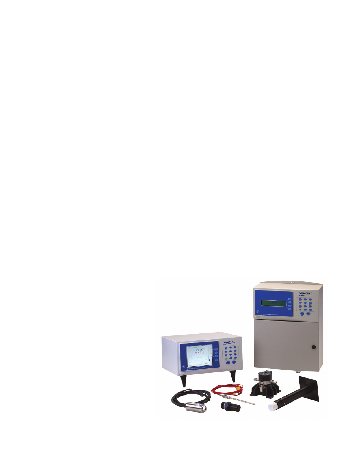
GE's Optica Series chilled mirror hygrometers offer
National Institute of Standards and Technologies (NIST)
_
traceable humidity, temperature and pressure
measurements for the connected generation. Now data
is accessible from anywhere, any time, from within a
browser over the Internet or from your intranet.
• Temperature
• Relative humidity (% RH)
• Dew/frost point (Td)
• Absolute humidity (m/v)
• Mass mixing ratio (m/m)
• Volume mixing ratio (v/v)
Optica Measures
• Wet bulb (Tw)
• Enthalpy (h)
• Water vapor pressure (e)
• Pressure
• Alarm relays
• Analog outputs
Fundamental dew point measurement is a primary
measurement used as a transfer standard for calibrating
other humidity instruments and sensors. Chilled mirrors
are also the sensors of choice when process and
laboratory measurements call for high precision without
long term drift. Optica may be used with five, fully
interchangeable chilled mirror sensors to provide a
measurement range from -112°F to 185°F (-80°C to 85°C)
dew point with 0.36°F (0.2°C) or better accuracy. Inputs
for a 100 S RTD and silicon-based piezoresistive pressure
transducer ensure precision measurements, which are
used to convert the dew point to any metric, English or
user-defined unit of humidity measure.
g
Page 2
Communications
• Ethernet port
• Java-based applet loads in web browsers
• Data logger 6 megabyte memory
• Recorded data uploads in ASCII format
• Exports to spreadsheets
• Real time "strip chart" graphing
• Color VGA or 4 x 40 matrix display
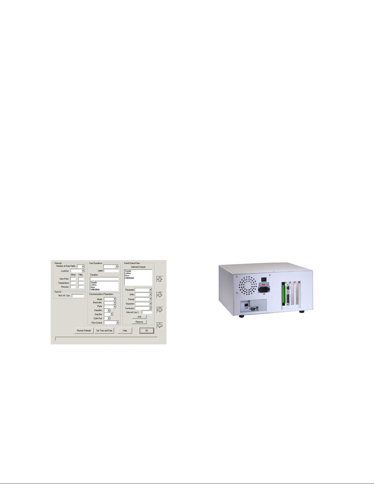
Software
The Optica software is easy to navigate. Users select
readout display, strip chart, analog output scale, digital
communications, self-diagnostics, cleaning and data
logging with intuitive pull-down menus. Setup values can
be saved in memory and loaded anytime, either locally or
from anywhere via the Ethernet port.
In the Lab or on the Plant Floor
• Calibration labs
• Process control
• Clean rooms
• Environmental test chambers
• Precision HVAC monitoring and control
• Fuel cells
• Heat exchanger and refrigerant coil calorimeters
• Thermal processing/heat treating
• Semiconductor manufacturing
• Storage areas
• Pharmaceutical validation chambers
• Engine test cells and emissions testing
• Aircraft engines and turbines
Functionality
The Optica simultaneously measures dew point,
temperature and pressure. The analyzer is equipped with
programmable math functions to produce custom units.
In, exp +, -, x and / functions enable derived engineering
units to be displayed, recorded and transmitted to data
acquisition systems. The analyzer input channel is a
standard 4 to 20 mA/0 to 5 VDC input, so the Optica can
be connected to any type of process transmitter and be
configured to display engineering units.
Chilled Mirror Sensors Theory of
Operation
GE’s chilled mirror hygrometers are used in standards
and metrology labs as well as in industrial applications
where precise and repeatable humidity measurement
and control is required. The inherent accuracy and long
term stability provides many advantages over other
types of humidity measurement technologies. Chilled
mirrors fundamentally measure the dew or frost point
temperature directly by controlling a reflective surface to
an equilibrium temperature between dew/frost
formation and evaporation, and precisely measuring the
temperature of the mirror at this point.
“Plug and play” setup is easily accomplished with
standard connectors for power, sensor and analog outputs.
GE
Sensing
Page 3
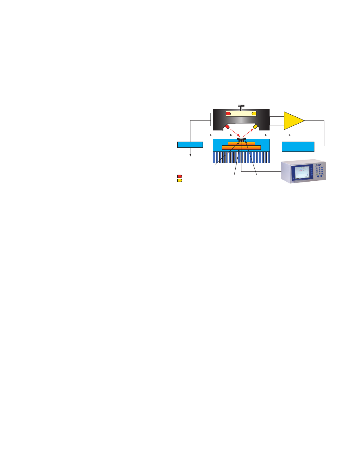
GE's chilled mirrors consist of a small polished hexagonal
rhodium, or platinum mirror attached to thermoelectric
cooling module (TEC). The Optica analyzer's servo
controller applies current to the TEC, which causes the
mirror to cool. The mirror is illuminated with a regulated
Gas emitter, which transmits light in the infrared
spectrum. The light reflected by the mirror is received by
a photodetector. When water vapor condenses on the
mirror as water or frost (ice crystals), the light received
by the photodetector is reduced due to scattering. This
results in the servo controller reducing the power
causing the mirror to slightly warm. The Optica's control
system will modulate the amount of current flowing
though the TEC to maintain a temperature where the
rate of condensation and evaporation of water
molecules and the mass of water on the mirror is
constant. The resulting temperature of the mirror is then,
fundamentally by definition, equal to the dew or frost
point temperature. A precision four-wire platinum RTD
imbedded in the mirror measures the temperature. The
accuracy of the dew point measurement has been
validated to an accuracy of ±0.36°F (±0.2°C) dew/frost
point. The precision can also be enhanced to ±0.27°F
(±0.15°C) dew/frost point.
Dry bulb temperature is measured with a precise
four-wire 100 S platinum RTD and pressure is measured
with a piezoresistive silicon pressure transducer. The
dew/frost point and dry bulb RTD resistance signals are
conditioned and amplified by the Optica monitor to
display and transmit dew/frost point and temperature.
The pressure sensor transmits an amplified 4 to 20 mA
signal that is powered by the Optica. The cardinal
measurements of dew/frost point, dry bulb temperature
and pressure are used to calculate other humidity
parameters such as relative humidity, wet bulb, mass
mixing ratio, volumetric mixing ratio, absolute humidity,
enthalpy and water vapor pressure values using
psychometric equations.
The RTD sensor is imbedded in the chilled mirror and
never comes in contact with the process or test
environment. The wetted parts consist of the platinum or
rhodium mirror, a stainless steel or mylar vapor barrier
and epoxy sealant. The net result is drift-free humidity
measurement designed to maintain accuracy
specifications for many years.
Chilled mirrors require a nominal flow rate across the
mirror to achieve the optimal dew/frost formation and
response time. The sensor should either be installed in a
duct with moving air or be equipped with a sampling
pump. The optimum flow rate is 0.5 to 5 SCFH (0.25 to
2.5 L/min). GE provides sampling systems to temperature
condition, regulate the pressure and filter process air
prior to reaching the chilled mirror. Our application
engineers will discuss your application in detail and
provide a recommendation for the system best suited to
your needs.
Self Cleaning and Digital Control
LED regulation
Thermoelectric
heat pump control
OP
AMP
Light emitting diodes
Photo detectors
Thermoelectric
cooling module
Rhodium or
platinum mirror
Precision four-wire PRTD
Power
Optical balance
Gas flow
For environments where physical contaminants such as
dust, oil mist and pollen are present, the use of a
sampling system with a filter media is recommended.
The filter media must be hydrophobic so as to not
absorb or release water vapor into the test stream. Over
time the mirror can be etched or pitted by particulate,
altering the light scattering characteristics. GE mirrors
are field replaceable. The standard rhodium mirror may
be upgraded to platinum for industrial applications.
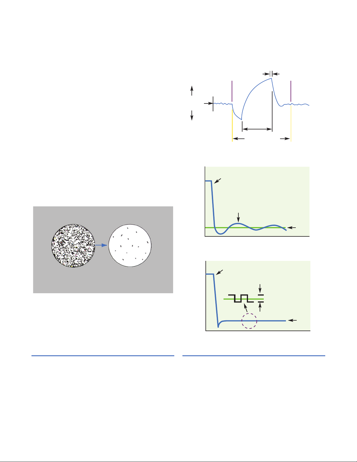
GE developed a patented contamination compensation
scheme called PACER®(Program Automatic Error
Reduction). The PACER cycle may be initiated manually or
by programming a timed cycle. The cycle starts by
capturing the data (during the PACER cycle a constant
value is transmitted) and cooling the mirror well below
the dew point such that a thick dew layer forms on the
mirror. The mirror is then rapidly heated. During the
heating a significant amount of soluble and some
non-soluble contamination is flash evaporated. The
contamination left on the mirror tends to aggregate in
dry islands or spots (much like a glass that comes out of
a dishwasher). This process leaves approximately 85% of
the mirror clean. The light signal received by the
photodetector is compared against a reference
LED/photodetector and the two signals are "balanced,"
effectively negating the effect of the residual
contamination left on the mirror. The PACER cycle works
very well, but eventually manual cleaning may be
required. All of GE's chilled mirrors are accessible for
GE
Sensing
Page 4
PACER cycle
Before PACER cycle
After PACER cycle
Data is sampled
and held (3 minutes)
Mirror heats
to dry state
(90 seconds)
Mirror returns
to dew point
(60 seconds)
Mirror cools
and coalesces
(30 seconds)
Optical system
automatically adjusts
for correct reflectance
(5 seconds)
Prevailing
dew point
Cooling
Heating
End
of cycle
Start
of cycle
Typical PACER cycle
Slew rate
Dew
point
Oscillation
Time
Temperature
Analog control
Time
Temperature
Digiloop control
Slew rate
Dew
point
0.05°C temperature steps
manual cleaning. Cleaning is a simple process consisting
of wiping the mirror with a cotton swab wetted with
cleaning solution or distilled water. (Distilled water is
recommended as the final cleaning agent .)
GE developed Digiloop™ control to overcome the
limitations of traditional analog PID (Proportional Integral
and Derivative) control. Analog temperature control
produces oscillations particularly at high or trace
humidity levels. It is difficult to apply self-tuning or PID
constants to analog control loops, which are over
damped or under damped. Digiloop utilizes digital
sampling and feed-forward control by taking time-based
samples when the dew point is within a predetermined
proportional band. By recording the oscillations, the
digital control effectively predicts the magnitude of
change and adjusts the current to the thermoelectric
cooling module, which steps the mirror temperature in
0.09°F (0.05°C) increments. This results in a significantly
improved control and dew point precision.
GE
Sensing
Page 5
Models
• Color VGA with data logger and Ethernet
communications available in bench, rack or wall
mount styles
• 4 x 40 dot matrix available in bench, rack or wall
mount styles
Power
95 to 265 VAC, 50/60 Hz, 200 watts
Electrical I/O
IEC-style AC receptacle (bench mount), screw terminal
block (wall mount), multipin chilled mirror and
temperature sensor/cable connectors, screw terminals
for analog outputs, DB-9 for RS232 and 10 base-T for
Ethernet*
Measured Parameters
Dew point, temperature and 4 to 20 mA/0 to 5 VDC
Calculated Parameters
Relative humidity, wet bulb, mass mixing ratio, volumetric
mixing ratio, absolute humidity, water vapor pressure
and enthalpy in English and metric units, as well as userconfigured units
Inputs
1/3 Class A DIN 43760, 100 S RTD and dew/frost point
and dry bulb temperature. Loop powered 4 to 20 mA DC
at 500 S maximum load
Accuracy
System accuracy ±0.36°F (±0.2°C) for dew/frost point,
±0.27°F (±0.15°C) for temperature, 0.5% full scale (FS) for
pressure
Range
Governed by sensor
Hystersis
Negligible
Sensitivity
0.1% FS
A/D
16 bit
Optica
Specifications
Data Logger Memory
6 megabytes*
Display
1/4 color VGA enables up to six parameters to be
displayed or 4 x 40 dot matrix enables three parameters
to be displayed
Operating Temperature
32°F to 122°F (0°C to 50°C)
Cooling Rate
0.27°F (1.5°C )/sec typical above 32°F (0°C)
Digital Interface
RS232 port, Ethernet port*
Digital Output Format
Data ASCII text, Ethernet java applet password
protected*
TCP/IP Address
User programmable*
Analog Outputs
(2) 4 to 20 mA and 0 to 5 VDC, user configurable and
scalable
Analog Outputs
(2) 5 A at 250 V, form C, (SPDT) relays
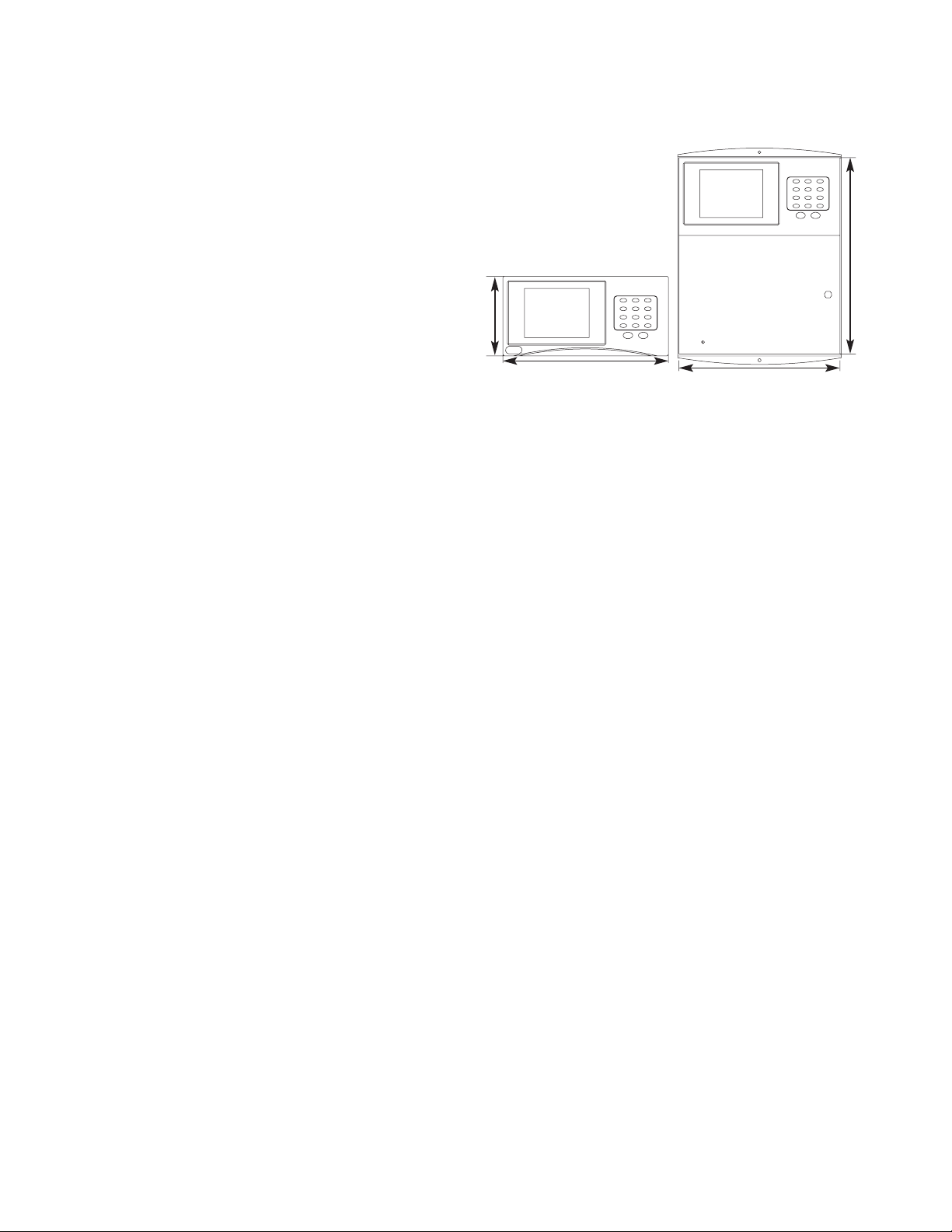
Enclosure
Benchtop: Type 1
Wall Mount: Type 4
Weight
Benchtop: 8 lb (3.6 kg)
Wall Mount: 10 lb (4.5 kg)
*Feature available with VGA models only
16.5 in (419 mm)
13.5 in (343 mm)
13.5 in (343 mm)
6.5 in
(165 mm)
Bench Top Wall Mount
GE
Sensing
Page 6
Sensing Element
Four-wire 1/3 Class A DIN 43760 RPT, 100 S @ 32°F (0°C)
Dew/Frost Point Accuracy
Standard: ±0.36°F (±0.2°C)
Optional: ±0.27°F (±0.15°C)
Sensitivity
>0.05°F (>0.03°C)
Repeatability
±0.09°F (±0.05°C)
Hysteresis
Negligible
Cooling Stages
Single stage thermoelectric cooling (TEC) module
Auxiliary Cooling
Not applicable
Depression
81°F (45°C) at 77°F (25°C) dry bulb and atmospheric
pressure
Typical Measurement Range
5°F to 77°F (-15°C to 25°C) dew/frost point (Td) in air @
77°F (25°C) and atmospheric pressure. Equivalent to 5%
to 100% RH.
Other humidity parameters based on calculations.
Sample Flow
0.5 to 5.0 SCFH (0.25 to 2.5 L/min)
Operating Temperature
5°F to 176°F (-15°C to 80°C)
Pressure
-3 to 200 psig (0.8 to 15 bar)
1111H
Single-Stage
Chilled Mirror
Specifications
Power
Derived from Optica
Sensor Body
Epoxy-coated aluminum
Filter
Polytetrafluoroethylene (PTFE) filter (standard on
1111H-GE)
Mirror
Standard: Rhodium-plated copper
Optional: Solid platinum
Sensor Wetted Material
Aluminum, copper, mylar, PTFE, rhodium or platinum
Vapor Barrier
Mylar
Electrical Connector
MS-style multipin connector
Weight
1 lb (1.4 kg) net
Accessories
MB-11 Wall mounting bracket
PTFE-GE PTFE filter
P Platinum mirror
X Enhanced accuracy ±0.27°F (±0.15°C) Td
O111D Pressure boss (1111H only)
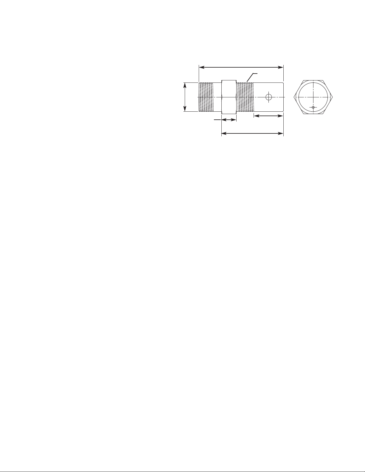
1.23 in
(31 mm)
.62 in
(16 mm)
2.57 in (65 mm)
3.5 in
(89 mm)
Ø 1.2 in
(30 mm)
1 in NPT
GE
Sensing
Page 7

Sensing Element
Four-wire 1/3 Class A DIN 43760 RPT, 100 S @ 32°F (0°C)
Dew/Frost Point Accuracy
Standard: ±0.36°F (±0.2°C)
Optional: ±0.27°F (±0.15°C)
Sensitivity
>0.05°F (>0.03°C)
Repeatability
±0.09°F (±0.05°C)
Hysteresis
Negligible
Cooling Stages
Two-stage TEC module
Auxiliary Cooling
Not applicable
Depression
117°F (65°C) at 77°F (25°C) and atmospheric pressure
Typical Measurement Range
31°F to 77°F (-35°C to 25°C) dew/frost point (Td) in air @
77°F (25°C) and atmospheric pressure. Equivalent to 0.7%
to 100% RH.
Other parameters based on calculations.
Sample Flow
0.5 to 5.0 SCFH (0.25 to 2.5 L/min)
Operating Temperature
-13°F to 185°F (-25°C to 85°C)
Pressure
150 psig (11 bar) maximum
Power
Derived from Optica monitor
D2 Two-Stage
Chilled Mirror
Specifications
Sensor Body
Cast aluminum with 314 stainless steel flow cell
Mirror
Standard: Rhodium-plated copper
Optional: Solid platinum
Sensor Wetted Material
302, 316 stainless steel, silicone o-ring, BK-7 glass,
rhodium or platinum mirror
Vapor Barrier
Stainless steel
Inlet/Outlet
1/4 in OD tubing compression fittings
Electrical Connector
Sub-D 15-pin connector mates with 2130 cable
Weight
4 lb (1.8 kg) net
Accessories
P Platinum mirror
X Enhanced accuracy ±0.27°F (±0.15°C) Td
4.5 in
(114 mm)
square
Ø .107 in (4.75 mm) through 4 places
1/4 in
compression
stainless steel
4 in
(102 mm)
GE
Sensing
Page 8

Sensing Element
Four-wire 1/3 Class A DIN 43760 RPT, 100 S @ 32°F (0°C)
Dew/Frost Point Accuracy
Standard: ±0.36°F (±0.2°C)
Optional: ±0.27°F (±0.15°C)
Sensitivity
>0.05°F (>0.03°C)
Repeatability
±0.09°F (±0.05°C)
Hysteresis
Negligible
Cooling Stages
Two-stage TEC module
Depression
117°F (65°C) at 77°F (25°C) and atmospheric pressure
Typical Measurement Range
31°F to 77°F (-35°C to 25°C) dew/frost point (Td) in air @
77°F (25°C) and atmospheric pressure. Equivalent to 0.7%
to 100% RH.
Other parameters based on calculations.
Sample Flow
0.5 to 5.0 SCFH (0.25 to 2.5 L/min)
Operating Temperature
5°F to 212°F (-15°C to 100°C)
Pressure
300 psig (21 bar) maximum
Power
Derived from Optica
1211H
Two-Stage
Chilled Mirror
Specifications
Sensor Body
Cast aluminum with 314 stainless steel flow cell
Mirror
Standard: Rhodium-plated copper
Optional: Solid platinum
Sensor Wetted Material
302, 316 stainless steel, silicone o-ring, BK-7 glass,
rhodium or platinum mirror
Vapor Barrier
Mylar (upgradeable to stainless steel)
Inlet/Outlet
1/4 in OD tubing compression fittings
Electrical Connector
MS-style multipin connector mates with 2120 cable
Weight
4 lb (1.8 kg) net
Accessories
P Platinum mirror
X Enhanced accuracy ±0.27°F (±0.15°C) Td
S Stainless steel vapor barrier
5 in
(127 mm)
3.6 in
(91.44 mm)
5.7 in
(144.78 mm)
3.1 in
(78.74 mm)
1/4 in
(6.35 mm)
compression
fitting
GE
Sensing
GE Infrastructure
Sensing
1211H
Page 9

Sensing Element
Four-wire 1/3 Class A DIN 43760 RPT, 100 S @ 32°F (0°C)
Dew/Frost Point Accuracy
Standard: ±0.36°F (±0.2°C)
Optional: ±0.27°F (±0.15°C)
Sensitivity
>0.05°F (>0.03°C)
Repeatability
±0.09°F (±0.05°C)
Hysteresis
Negligible
Cooling Stages
Two-stage TEC module
Auxiliary Cooling
Not applicable
Depression
153°F (85°C) at 167°F (75°C) body temperature and
atmospheric pressure
Typical Measurement Range
14°F to 167°F (-10°C to 75°C) dew/frost point (Td) in air @
167°F (75°C) body temperature in 77°F (25°C) ambient
temperature and atmospheric pressure. Equivalent to
0.7% to 100% RH.
Other parameters based on calculations.
Sample Flow
0.5 to 5.0 SCFH (0.25 to 2.5 L/min)
Operating Temperature
5°F to 212°F (-15°C to 100°C)
SIM-12 Heated
Two-Stage
Chilled Mirror
Specifications
Heater Control
Thermostatically controlled. Set point of 77°F (25°C),
104°F (40°C), 131°F (55°C), 158°F (70°C), 185°F (85°C) and
212°F (100°C)
Pressure
50 psig (4.5 bar) maximum
100/115/230 VAC, 50/60 Hz, 75 watts
Sensor Body
Cast aluminum with 314 stainless steel flow cell
Sensor Wetted Material
302, 316 stainless steel, silicone o-ring, BK-7 glass,
rhodium or platinum mirror
Mirror
Standard: Rhodium plated copper
Optional: Solid platinum
Vapor Barrier
Mylar (upgradeable to stainless steel)
Electrical Connector
MS-style multipin connector
IEC receptacle for AC power
Weight
7 lb (3.2 kg) net
Accessories
P Platinum mirror
X Enhanced accuracy ±0.27°F (±0.15°C) Td
S Stainless steel vapor barrier
HSS-12 Heated sampling system. SIM-12 heated
chilled mirror, SIM-HFT heated filter module
and SIM-HFM heated flowmeter mounted
on a plate with SIM-HSL heated sample line.
4 in
(102 mm)
8.64 in (219 mm)
3.5 in
(89 mm)
.25 in compression fitting
GE
Sensing
Inlet
ON
°C
°F
Outlet
25
25
°C
105
77
°F
Max Dewpoint
Ready
Model SIM-12H
Heated Sensor
55
130
70
85
160
185
25
25
Page 10

Sensing Element
Four-wire 1/3 Class A DIN 43760 RPT, 100 S @ 32°F (0°C)
Dew/Frost Point Accuracy
Standard: ±0.36°F (±0.2°C)
Optional: ±0.27°F (±0.15°C)
Sensitivity
>0.05°F (>0.03°C)
Repeatability
±0.09°F (±0.05°C)
Hysteresis
Negligible
Cooling Stages
Four-stage TEC module
Auxiliary Cooling
Liquid cooling jacket
Depression, Air Cooled
171°F (95°C) at 77°F (25°C) and atmospheric pressure
Depression, Liquid Cooled
189°F (105°C) with 59°F (15°C) cooling water
Typical Measurement Range
• -85°F to 77°F (-65°C to 25°C) dew/frost point (Td) in air
@ 77°F (25°C) and atmospheric pressure.
• -103°F to 59°F (-75°C to 15°C) in liquid-cooled mode
with 59°F (15°C) coolant.
Other parameters based on calculations.
Sample Flow
0.5 to 5.0 SCFH (0.25 to 2.5 L/min)
Operating Temperature
32°F to 95°F (0°C to 35°C)
1311-DR
Four-Stage
Chilled Mirror
Specifications
Pressure
300 psig (22 bar) maximum
Power
100/115/230 VAC, 50/60 Hz, 300 watts
Sensor Body
Cast aluminum with 314 stainless steel flow cell
Mirror
Standard: Rhodium-plated copper
Optional: Solid platinum
Sensor Wetted Material
302, 316 stainless steel, silicone o-ring, BK-7 glass,
rhodium or platinum mirror
Vapor Barrier
Mylar (upgradeable to stainless steel)
Inlet/Outlet
1/4 in (6 mm) OD tubing compression fittings
Electrical Connector
MS-style multipin connector mates
IEC receptacle for AC power
Weight
34 lb (16 kg) net
Accessories
P Platinum mirror
X Enhanced accuracy ±0.27°F (±0.15°C) Td
S Stainless steel vapor barrier
8.77 in
(223 mm)
1.8 in
(46 mm)
7.17 in
(182 mm)
Ø 0.31 in
(7.9 mm)
4 places
16.3 in
(414 mm)
GE
Sensing
1311DR
Control
Air Cooling
Liquid Cooling
~ Input Power
Page 11

Sensing Element
Four-wire 1/3 Class A DIN 43760 RPT, 100 S @ 32°F (0°C)
Dew/Frost Point Accuracy
Standard: ±0.27°F (±0.15°C)
Sensitivity
>0.05°F (>0.03°C)
Repeatability
±0.09°F (±0.05°C)
Hysteresis
Negligible
Cooling Stages
Five-stage TEC module
Auxiliary Cooling
Liquid cooling jacket
Depression, Liquid Cooled
202°F (112°C) with 59°F (15°C) cooling water
Typical Measurement Range
-112°F to 59°F (-80°C to 15°C) dew/frost point (Td) in air
@ 77°F (25°C) and atmospheric pressure with 59°F (15°C)
cooling water.
Other parameters based on calculations.
Sample Flow
0.5 to 5.0 SCFH (0.25 to 2.5 L/min)
Operating Temperature
32°F to 95°F (0°C to 35°C)
Pressure
0 to 100 psig (1 to 8 bar)
1311-XR
Five-Stage
Chilled Mirror
Specifications
Power
115/230 VAC, 50/60 Hz, 700 watts
Sensor Body
314 stainless steel
Mirror
Standard: Rhodium-plated copper
Optional: Solid platinum
Sensor Wetted Material
302, 316 stainless steel, silicone o-ring, BK-7 glass,
rhodium or platinum mirror
Vapor Barrier
Mylar (upgradeable to stainless steel)
Inlet/Outlet
1/4 in OD tubing compression fittings
Electrical Connector
MS-style multipin connector
IEC receptacle for AC power
Weight
50 lb (26 kg) net
Accessories
P Platinum mirror
S Stainless steel vapor barrier
6.95 in
(176.5 mm)
5.2 in
(132 mm)
19 in
(483 mm)
5.3 in
(135 mm)
9 in
(129 mm)
GE
Sensing
g
1311XR
1311XR
g
Page 12

Sensing Element
Four-wire 1/3 Class A DIN 43760 RPT, 100 S @32°F ( 0°C)
Accuracy
System at 25°C
Standard: ±0.27°F (±0.15°C)
Optional: ±0.18°F (±0.1°C)
Measurement Range
-148°F to 212°F (-100°C to 100°C)
Response Time
7 seconds for 77°F to 158°F (25°C to 70°C) step change in
fluid
Sensor Body
Stainless steel sheath
T-100
Four-Wire PRTD
Temperature
Mirror
Specifications
Cable
PTFE insulation rated to 302°F ( 150°C). 10 ft (3 m)
standard length.
Fittings
Adjustable 1/4 in NPT stainless steel compression fitting
Strain Relief
Stainless steel spring
Power
Low voltage derived from Optica
Weight
2 lb (0.9 kg) net
Options
Additional cable length
7.5 in (190.5 mm)
Ø .25 in
(6.35 mm)
1/4 in NPT
Connector
PTFE cable, 305°F (150°C), 10 ft (3 m)
standard length
GE
Sensing
Page 13

Sensing Element
Micro-machined silicon strain gauge
Accuracy
System at 77°F (25°C), ±0.5% of full scale
Range PT-30A
0 to 30 psia (0 to 2 bar)
Range PT-300A
0 to 300 psia (0 to 21 bar)
Response Time
1 second for 90% of steady state (10% to 90% change)
Operating Ranges
• -4°F to 176°F (-20°C to 80°C) ambient temperature
• -13°F to 248°F (-25°C to 120°C) process temperature
Temperature Effect
<1% FS on accuracy from 14°F to 122°F (-10°C to 50°C)
for pressure 6 psi (0.4 bar)
PT Series
Pressure
Transducer
Specifications
Power
9 to 30 VDC. Derived from Optica monitor.
Sensor Body Material
316 stainless steel
Sensor Wetted Material
316 stainless steel and Hastelloy diaphragm
Cable
PVC insulation. 10 ft (3 m) standard length process
connection 1/4 in F-NPT.
Weight
4 lb (1.8 kg) net
5.03 in
(1.28 mm)
1.5 in
(38 mm)
10 ft (3 m)
standard
length
GE
Sensing
Page 14

Enclosure
Polycarbonate
Fittings
Brass 1/4 in OD tubing
Compression Internal Tubing
Impolene
Rotameter
0.5 to 5 SCFH (0.2 to 2 L/min)
Maximum Vacuum
-98 in (-250 mm) of Hg
SSM Sampling
System
Specifications
Free Air Displacement
14 SCFH (6.5 L/min)
Maximum Temperature
100°F (38°C)
Power
95 to 265 VAC, 50/60 Hz, 15 watts
3.30 in
(84 mm)
6.70 in (170 mm)
Power
input
module
SSM Sampling System
In Out
2.68 in
(68 mm)
Output gas
fittings
Input gas fittings
GE
Sensing
Page 15

Appendix
1111H Single-Stage Chilled Mirror
Sensor Body Temperature °C
100
75
50
25
0
-25
-50
-75
-100
-50 -25 0 25 50 75 100
Mirror
depression
Sensor Body Temperature °C
Dew Frost Point Temperature °F (°C)
45°C depression
D2 Two-Stage Chilled Mirror
Sensor Body Temperature °C
100
75
50
25
0
-25
-50
-75
-100
-50 -25 0 25 50 75 100
Mirror
depression
Sensor Body Temperature °C
Dew Frost Point Temperature °F (°C)
65°C depression
1211H Two-Stage Chilled Mirror
Sensor Body Temperature °C
100
75
50
25
0
-25
-50
-75
-100
-50 -25 0 25 50 75 100
Mirror
depression
Sensor Body Temperature °C
Dew Frost Point Temperature °F (°C)
65°C depression
SIM-12 Heated
Two-Stage Chilled Mirror
Sensor Body Temperature °C
100
75
50
25
0
-25
-50
-75
-100
-50 -25 0 25 50 75 100
Mirror
depression
Sensor Body Temperature °C
Dew Frost Point Temperature °F (°C)
65°C depression
GE
Sensing
Page 16

Appendix
1311-DR Four-Stage Chilled Mirror
Sensor Body Temperature °C
50
25
0
-25
-50
-75
-100
-50 -25 0 25 50 75 100
Mirror
depression
Ambient Air Temperature °C
Dew Frost Point Temperature °F (°C)
95°C depression
1311-XR Five-Stage Chilled Mirror
Sensor Body Temperature °C
100
75
50
25
0
-25
-50
-75
-100
-50 -25 0 25 50 75 100
Mirror
depression
Sensor Body Temperature °C
Dew FrostPoint Temperature °F (°C)
112°C depression
GE
Sensing
Page 17

Recommended for dew points ≥32°F (≥0°C)
Materials
Anodized aluminum head, nylon bowl, nylon internals,
Buna-N Seals
Fittings
1/4 in compression
Temperature
-150°F to 220°F (-101°C to 104°C)
Filter
Borosilicate glass
Porosity
93% of particles over 0.1 µm
Pressure
150 psig (10 bar) maximum
BF-12SS
Box of 10 replacement filter elements
Accessories
BF-10DX General Purpose Filter
Recommended for dew points ≤32°F (≤0°C)
Materials
316 stainless steel head, bowl and internals. Viton seals
Fittings
1/4 in (6 mm) compression
Temperature
-150°F to 220°F (-101°C to 104°C)
Filter
Borosilicate glass
Porosity
93% of particles over 0.1 µm
Pressure
340 bar (5000 psig) maximum
BF-12SS
Box of ten replacement filter elements
BF-12SS Stainless Steel Filter
Materials
Clear acrylic body, Buna-N Seals, black glass float, brass
valves
Fittings
1/4 in compression
Range
0.5 to 5 SCFH (0.2 to 2 L/min)
Pressure
100 psig (6 bar) maximum
Temperature
150°F (65°C) maximum
FM-1 Rotameter/Needle Valve
5.4 in
(136 mm)
.6 in
(14 mm)
2.7 in
(70 mm)
1/4 in
compression
outlet and
inlet ports
1.75 in (44 mm)
3.53 in
(90 mm)
1.19 in (30 mm)
GE
Sensing
Page 18

Optica Monitor
Color VGA Display With Logger/Ethernet
A Benchtop
B Benchtop with rack mount bracket
C Wall mount
Four-color, 40 Alphanumeric Display
D Benchtop
E Benchtop with rack mount bracket
F Wall mount
Optica Channel One
1 Unit to be sold with new chilled mirror
(see sensor section)
2 Use the existing D2
(conversion cable 2160 required)
3 Use with existing 1111H, 1211H, SIM-12H and
1311DR (conversion cable 2160 required)
4 Use with existing 1311XR
(conversion cable 2140 required)
Default Code
0 Default code
Ordering Code
Guide
Chiller Mirror Cable
Cable Type
0 No cable required
C Adaptor cable for existing sensor/cable
installation 2 ft (.61 m)
A 10 ft (3 m) standard length
X Specify length in ft (m)
O
P A 1 O A C 1 A O
2120 For use with 1111H, 1211H, SIM12,
HSS-12, 1311DR sensors
2130 For use with D2
2140 For use with 1311XR
2150 For use with Optica CCD sensor
2160 Adaptor cable for sensors except 1311XR
2 ft (0.61 mm)
2170 Adaptor cable for 1311XR 2 ft (0.61 mm)
Chilled Mirror Sensor
Sensor
0 No sensor
A 1111H
B 1111H-GE
C D2
D 1211H
SIM-12
E 100 VAC
F 115 VAC
G 230 VAC
HSS-12
H 100 VAC
J 115 VAC
K 230 VAC
1311DR
L 100 VAC
M 115 VAC
N 230 VAC
1311XR
P 100 VAC
Q 115 VAC
R 230 VAC
GE
Sensing
Page 19

Accuracy And Mirror
1 S/R/M standard accuracy, rhodium mirror,
mylar vapor barrier
2 S/P/M standard accuracy, platinum mirror,
mylar vapor barrier
3 S/P/P standard accuracy, platinum mirror,
stainless steel vapor barrier
4 X/R/M enhanced accuracy, rhodium mirror,
mylar vapor barrier
5 X/P/M enhanced accuracy, platinum mirror,
mylar vapor barrier
6 X/P/P enhanced accuracy, platinum mirror,
stainless steel vapor barrier
7 S/R/P standard accuracy, rhodium mirror,
stainless steel vapor barrier (D2)
8 X/R/P enhanced accuracy, rhodium mirror,
stainless steel vapor barrier (D2)
9 S/P/P standard accuracy, platinum mirror,
stainless steel vapor barrier (D2)
Ordering Code
Guide
Temperature Sensor
Sensor
0 No temperature sensor
A T-100 with 10 ft (3 m) cable (standard accuracy)
B T-100 with 10 ft (3 m) cable (enhanced accuracy)
X T-100 with build to fit cable (standard accuracy)
Z T-100 with 10 ft (3 m) cable (enhanced accuracy)
Pressure Sensors
0 No pressure sensor
A PT-30A 10 ft (3 m) cable (standard)
B PT-30A build-to-fit cable
X PT-300A 10 ft (3 m) cable (standard)
Z PT-300A build-to-fit cable
GE
Sensing
Page 20

©2005 GE. All rights reserved.
920-076C
All specifications are subject to change for product improvement without notice.
Optica™ is a trademark of GE. GE®is a registered trademark of General Electric Co.
Other company or product names mentioned in this document may be trademarks or
registered trademarks of their respective companies, which are not affiliated with GE.
g
www.gesensing.com
GE
Sensing
 Loading...