

Page 1

GE
Sensing & Inspection Technologies
TransPort™ PT878GC
Portable Gas Flowmeter
User’s Manual
Page 2

GE
Sensing & Inspection Technologies
TransPort™ PT878GC
Portable Gas Flowmeter
User’s Manual
910-229B3
April 2009
Page 3

April 2009
Warranty
Each instrument manufactured by GE Infrastructure Sensing,
Inc. is warranted to be free from defects in material and
workmanship. Liability under this warranty is limited to
restoring the instrument to normal operation or replacing the
instrument, at the sole discretion of GE Infrastructure Sensing,
Inc. Fuses and batteries are specifically excluded from any
liability. This warranty is effective from the date of delivery to
the original purchaser. If GE Infrastructure Sensing, Inc.
determines that the equipment was defective, the warranty
period is:
• one year from delivery for electronic or mechanical failures
• one year from delivery for sensor shelf life
If GE Infrastructure Sensing, Inc. determines that the
equipment was damaged by misuse, improper installation, the
use of unauthorized replacement parts, or operating
conditions outside the guidelines specified by GE
Infrastructure Sensing, Inc. , the repairs are not covered under
this warranty.
The warranties set forth herein are exclusive and are in lieu
of all other warranties whether statutory, express or
implied (including warranties or merchantability and fitness
for a particular purpose, and warranties arising from course
of dealing or usage or trade).
iii
Page 4

April 2009
Return Policy
If a GE Infrastructure Sensing, Inc. instrument malfunctions
within the warranty period, the following procedure must be
completed:
1. Notify GE Infrastructure Sensing, Inc., giving full details of
the problem, and provide the model number and serial
number of the instrument. If the nature of the problem
indicates the need for factory service, GE Infrastructure
Sensing, Inc. will issue a RETURN AUTHORIZATION NUMBER
(RAN), and shipping instructions for the return of the
instrument to a service center will be provided.
2. If GE Infrastructure Sensing, Inc. instructs you to send your
instrument to a service center, it must be shipped prepaid
to the authorized repair station indicated in the shipping
instructions.
3. Upon receipt, GE Infrastructure Sensing, Inc. will evaluate
the instrument to determine the cause of the malfunction.
Then, one of the following courses of action will then be taken:
• If the damage is covered under the terms of the warranty,
the instrument will be repaired at no cost to the owner and
returned.
• If GE Infrastructure Sensing, Inc. determines that the
damage is
if the warranty has expired, an estimate for the cost of the
repairs at standard rates will be provided. Upon receipt of
the owner’s approval to proceed, the instrument will be
repaired and returned.
iv
not covered under the terms of the warranty, or
Page 5

April 2009
Table of Contents
Chapter 1: Features and Capabilities
Overview . . . . . . . . . . . . . . . . . . . . . . . . . . . . . . . . . . . . . . . . . . . . . . . . . . . . . . 1-1
System Description . . . . . . . . . . . . . . . . . . . . . . . . . . . . . . . . . . . . . . . . . . . . 1-3
The Flowcell. . . . . . . . . . . . . . . . . . . . . . . . . . . . . . . . . . . . . . . . . . . . . . . 1-3
Electronics Package . . . . . . . . . . . . . . . . . . . . . . . . . . . . . . . . . . . . . . . 1-4
Theory of Operation . . . . . . . . . . . . . . . . . . . . . . . . . . . . . . . . . . . . . . . . . . . 1-5
Chapter 2: Initial Setup
Making Electrical Connections. . . . . . . . . . . . . . . . . . . . . . . . . . . . . . . . . . 2-2
Power Connections . . . . . . . . . . . . . . . . . . . . . . . . . . . . . . . . . . . . . . . . 2-3
Transducer Connections . . . . . . . . . . . . . . . . . . . . . . . . . . . . . . . . . . . 2-3
Analog Input/Output Connections . . . . . . . . . . . . . . . . . . . . . . . . . . 2-3
The Infrared Wireless Interface. . . . . . . . . . . . . . . . . . . . . . . . . . . . . 2-4
Charging and/or Replacing Batteries . . . . . . . . . . . . . . . . . . . . . . . . . . . 2-5
Charging the Batteries. . . . . . . . . . . . . . . . . . . . . . . . . . . . . . . . . . . . . 2-5
Replacing the Batteries . . . . . . . . . . . . . . . . . . . . . . . . . . . . . . . . . . . . 2-6
Powering On and Off. . . . . . . . . . . . . . . . . . . . . . . . . . . . . . . . . . . . . . . . . . . 2-7
Using the Screen and Keypad . . . . . . . . . . . . . . . . . . . . . . . . . . . . . . . . . 2-10
Screen . . . . . . . . . . . . . . . . . . . . . . . . . . . . . . . . . . . . . . . . . . . . . . . . . . . 2-10
Keypad . . . . . . . . . . . . . . . . . . . . . . . . . . . . . . . . . . . . . . . . . . . . . . . . . . 2-12
Obtaining On-Line Help . . . . . . . . . . . . . . . . . . . . . . . . . . . . . . . . . . . . . . . 2-14
Chapter 3: Installing the Dampening Material, Transducers
and Fixtures
Application Requirements. . . . . . . . . . . . . . . . . . . . . . . . . . . . . . . . . . . . . . 3-3
Preparing the Pipe . . . . . . . . . . . . . . . . . . . . . . . . . . . . . . . . . . . . . . . . . . . . 3-10
Performing a Pipe Survey . . . . . . . . . . . . . . . . . . . . . . . . . . . . . . . . . 3-11
Obtaining the Transducer Spacing . . . . . . . . . . . . . . . . . . . . . . . . 3-13
Installing the V Series Clamping Fixture and Transducers . . . . . . . 3-14
Installing the Fixture . . . . . . . . . . . . . . . . . . . . . . . . . . . . . . . . . . . . . . 3-14
Installing the Transducers. . . . . . . . . . . . . . . . . . . . . . . . . . . . . . . . . 3-16
Installing the PI Fixture and Transducers. . . . . . . . . . . . . . . . . . . . . . . 3-18
Surveying the Pipe. . . . . . . . . . . . . . . . . . . . . . . . . . . . . . . . . . . . . . . . 3-18
Installing the First Bracket with a Chain or Strap . . . . . . . . . . . 3-21
Installing the Second Bracket with a Chain or Strap . . . . . . . . 3-22
Installing the Transducers. . . . . . . . . . . . . . . . . . . . . . . . . . . . . . . . . 3-23
v
Page 6

April 2009
Table of Contents (cont.)
Installing Dampening Material . . . . . . . . . . . . . . . . . . . . . . . . . . . . . . . . 3-25
Installing DMP-1 Dampening Material . . . . . . . . . . . . . . . . . . . . . 3-26
Installing DMP-1 Dampening Material with PI Fixture . . . . . . . 3-29
Installing DMP-3 Compound with All Fixtures. . . . . . . . . . . . . . . 3-31
Installing the PDJ Dampening Jacket . . . . . . . . . . . . . . . . . . . . . . 3-33
Chapter 4: Programming Site Data
Entering the Program Menu . . . . . . . . . . . . . . . . . . . . . . . . . . . . . . . . . . . . 4-2
Entering Transducer Parameters . . . . . . . . . . . . . . . . . . . . . . . . . . . . . . . 4-3
Parameters for Special Transducers . . . . . . . . . . . . . . . . . . . . . . . . 4-5
Entering Pipe Parameters . . . . . . . . . . . . . . . . . . . . . . . . . . . . . . . . . . . . . . 4-7
Entering Pipe Lining Parameters. . . . . . . . . . . . . . . . . . . . . . . . . . . . . . . 4-11
Entering Fluid Types and Speeds . . . . . . . . . . . . . . . . . . . . . . . . . . . . . . 4-13
Entering the Signal Path Parameters . . . . . . . . . . . . . . . . . . . . . . . . . . 4-15
Path Parameters for Clamp-On Transducers . . . . . . . . . . . . . . . 4-16
Entering the Standard Volume/
Mass Flow Parameters. . . . . . . . . . . . . . . . . . . . . . . . . . . . . . . . . . . . . . . . 4-17
Entering Inputs in the Standard Volume Option . . . . . . . . . . . . 4-19
Entering Mass Flow Parameters . . . . . . . . . . . . . . . . . . . . . . . . . . . 4-22
Entering Skan/Measure Parameters . . . . . . . . . . . . . . . . . . . . . . . . . . . 4-24
Entering Skan/Measure Integrate Parameters . . . . . . . . . . . . . 4-28
Entering Skan/Measure Count Parameters. . . . . . . . . . . . . . . . . 4-30
Entering Skan/Correlation Parameters. . . . . . . . . . . . . . . . . . . . . 4-32
Entering Analog Inputs. . . . . . . . . . . . . . . . . . . . . . . . . . . . . . . . . . . . . . . . 4-34
Entering General-Purpose Analog Inputs . . . . . . . . . . . . . . . . . . 4-34
Entering Analog Inputs in Standard Volume
or Mass Flow Option . . . . . . . . . . . . . . . . . . . . . . . . . . . . . . . . . . . . . . 4-37
Entering the Analog Output . . . . . . . . . . . . . . . . . . . . . . . . . . . . . . . . . . . 4-39
Entering the Digital Output . . . . . . . . . . . . . . . . . . . . . . . . . . . . . . . . . . . . 4-42
Entering User Functions. . . . . . . . . . . . . . . . . . . . . . . . . . . . . . . . . . . . . . . 4-46
Entering Correction Factors . . . . . . . . . . . . . . . . . . . . . . . . . . . . . . . . . . . 4-50
Entering Reynolds Correction . . . . . . . . . . . . . . . . . . . . . . . . . . . . . 4-50
Entering a Calibration Factor. . . . . . . . . . . . . . . . . . . . . . . . . . . . . . 4-53
vi
Page 7

April 2009
Table of Contents (cont.)
Chapter 5: Creating and Managing Sites
The Site Manager . . . . . . . . . . . . . . . . . . . . . . . . . . . . . . . . . . . . . . . . . . . . . . 5-2
Creating a New Site . . . . . . . . . . . . . . . . . . . . . . . . . . . . . . . . . . . . . . . 5-4
Opening an Existing Site . . . . . . . . . . . . . . . . . . . . . . . . . . . . . . . . . . . 5-6
Saving a Site . . . . . . . . . . . . . . . . . . . . . . . . . . . . . . . . . . . . . . . . . . . . . . 5-7
Saving a Site with a Different Name . . . . . . . . . . . . . . . . . . . . . . . . 5-8
Refreshing a Site . . . . . . . . . . . . . . . . . . . . . . . . . . . . . . . . . . . . . . . . . . 5-9
Renaming a Site . . . . . . . . . . . . . . . . . . . . . . . . . . . . . . . . . . . . . . . . . . . 5-9
Deleting a Site. . . . . . . . . . . . . . . . . . . . . . . . . . . . . . . . . . . . . . . . . . . . 5-10
Creating a Site Message . . . . . . . . . . . . . . . . . . . . . . . . . . . . . . . . . . 5-11
Printing a File. . . . . . . . . . . . . . . . . . . . . . . . . . . . . . . . . . . . . . . . . . . . . 5-13
Transferring a Site File to a PC. . . . . . . . . . . . . . . . . . . . . . . . . . . . . 5-13
Transferring a File as Text. . . . . . . . . . . . . . . . . . . . . . . . . . . . . . . . . 5-14
Transferring a File from a PC to the PT878GC . . . . . . . . . . . . . . 5-15
Listing Files by Name . . . . . . . . . . . . . . . . . . . . . . . . . . . . . . . . . . . . . 5-17
Listing Files in Chronological Order . . . . . . . . . . . . . . . . . . . . . . . . 5-17
Chapter 6: Displaying and Configuring Data
The Format Option. . . . . . . . . . . . . . . . . . . . . . . . . . . . . . . . . . . . . . . . . . . . . 6-2
The View Option . . . . . . . . . . . . . . . . . . . . . . . . . . . . . . . . . . . . . . . . . . . . . . . 6-4
The Limits Option . . . . . . . . . . . . . . . . . . . . . . . . . . . . . . . . . . . . . . . . . . . . . . 6-5
The Measurement Option . . . . . . . . . . . . . . . . . . . . . . . . . . . . . . . . . . . . . . 6-7
Customizing the Display Screen . . . . . . . . . . . . . . . . . . . . . . . . . . . . . . . . 6-9
Specifying the Number of Displayed Parameters. . . . . . . . . . . 6-10
Customizing Softkeys . . . . . . . . . . . . . . . . . . . . . . . . . . . . . . . . . . . . . 6-11
Managing Files — The Drive Manager . . . . . . . . . . . . . . . . . . . . . . . . . . 6-14
Refreshing a File. . . . . . . . . . . . . . . . . . . . . . . . . . . . . . . . . . . . . . . . . . 6-16
Transferring a File to a PC. . . . . . . . . . . . . . . . . . . . . . . . . . . . . . . . . 6-16
Transferring a File from a PC to the PT878GC . . . . . . . . . . . . . . 6-17
Deleting a File . . . . . . . . . . . . . . . . . . . . . . . . . . . . . . . . . . . . . . . . . . . . 6-19
Listing Files by Name . . . . . . . . . . . . . . . . . . . . . . . . . . . . . . . . . . . . . 6-20
Listing Files in Chronological Order . . . . . . . . . . . . . . . . . . . . . . . . 6-20
Accessing Meter Data —The About Option . . . . . . . . . . . . . . . . . . . . . 6-21
Chapter 7: Programming Meter Settings
Entering the Meter Menu. . . . . . . . . . . . . . . . . . . . . . . . . . . . . . . . . . . . . . . 7-2
Selecting Measurement Units . . . . . . . . . . . . . . . . . . . . . . . . . . . . . . . . . . 7-3
The Battery Charger . . . . . . . . . . . . . . . . . . . . . . . . . . . . . . . . . . . . . . . . . . . 7-5
Entering Date and Time. . . . . . . . . . . . . . . . . . . . . . . . . . . . . . . . . . . . . . . . 7-7
vii
Page 8

April 2009
Table of Contents (cont.)
Changing Date and Time Appearance (Locale) . . . . . . . . . . . . . . . . . . 7-9
Adjusting the Contrast . . . . . . . . . . . . . . . . . . . . . . . . . . . . . . . . . . . . . . . . 7-12
Setting Backlight Timeout . . . . . . . . . . . . . . . . . . . . . . . . . . . . . . . . . . . . . 7-14
Changing Communications Parameters . . . . . . . . . . . . . . . . . . . . . . . 7-15
Resetting Forward and Reverse Totals . . . . . . . . . . . . . . . . . . . . . . . . . 7-18
Setting Up User Tables . . . . . . . . . . . . . . . . . . . . . . . . . . . . . . . . . . . . . . . . 7-19
Taking a Bitmap Capture of a Current Screen . . . . . . . . . . . . . . . . . . 7-23
Chapter 8: Logging Data
Entering the Logging Menu. . . . . . . . . . . . . . . . . . . . . . . . . . . . . . . . . . . . . 8-2
The Log Manager . . . . . . . . . . . . . . . . . . . . . . . . . . . . . . . . . . . . . . . . . . . . . . 8-3
The File Menu. . . . . . . . . . . . . . . . . . . . . . . . . . . . . . . . . . . . . . . . . . . . . . . . . . 8-4
Setting up a New Log . . . . . . . . . . . . . . . . . . . . . . . . . . . . . . . . . . . . . . 8-5
Copying (Cloning) a Selected Log . . . . . . . . . . . . . . . . . . . . . . . . . . 8-10
Renaming a Log . . . . . . . . . . . . . . . . . . . . . . . . . . . . . . . . . . . . . . . . . . 8-11
Deleting a Log. . . . . . . . . . . . . . . . . . . . . . . . . . . . . . . . . . . . . . . . . . . . 8-11
Deleting All Logs. . . . . . . . . . . . . . . . . . . . . . . . . . . . . . . . . . . . . . . . . . 8-12
Refreshing a Log . . . . . . . . . . . . . . . . . . . . . . . . . . . . . . . . . . . . . . . . . 8-12
Printing a Log . . . . . . . . . . . . . . . . . . . . . . . . . . . . . . . . . . . . . . . . . . . . 8-13
Transferring a Log to a PC . . . . . . . . . . . . . . . . . . . . . . . . . . . . . . . . 8-13
The Log Menu . . . . . . . . . . . . . . . . . . . . . . . . . . . . . . . . . . . . . . . . . . . . . . . . 8-14
Stopping (Pausing) a Log. . . . . . . . . . . . . . . . . . . . . . . . . . . . . . . . . . 8-15
Restarting a Log. . . . . . . . . . . . . . . . . . . . . . . . . . . . . . . . . . . . . . . . . . 8-15
Ending a Log . . . . . . . . . . . . . . . . . . . . . . . . . . . . . . . . . . . . . . . . . . . . . 8-15
Pausing All Logs . . . . . . . . . . . . . . . . . . . . . . . . . . . . . . . . . . . . . . . . . . 8-16
Restarting All Logs. . . . . . . . . . . . . . . . . . . . . . . . . . . . . . . . . . . . . . . . 8-16
Ending All Logs . . . . . . . . . . . . . . . . . . . . . . . . . . . . . . . . . . . . . . . . . . . 8-16
View All Sites . . . . . . . . . . . . . . . . . . . . . . . . . . . . . . . . . . . . . . . . . . . . . 8-16
The View Menu . . . . . . . . . . . . . . . . . . . . . . . . . . . . . . . . . . . . . . . . . . . . . . . 8-17
Displaying Log Details . . . . . . . . . . . . . . . . . . . . . . . . . . . . . . . . . . . . 8-18
Displaying Log Data in Graphical Form . . . . . . . . . . . . . . . . . . . . 8-19
Displaying Log Data in Spreadsheet Form . . . . . . . . . . . . . . . . . 8-22
The Sort Menu . . . . . . . . . . . . . . . . . . . . . . . . . . . . . . . . . . . . . . . . . . . . . . . . 8-23
Listing Logs by Name . . . . . . . . . . . . . . . . . . . . . . . . . . . . . . . . . . . . . 8-23
Listing Logs in Chronological Order. . . . . . . . . . . . . . . . . . . . . . . . 8-23
Chapter 9: Servicing the PT878GC
Entering the Service Menu . . . . . . . . . . . . . . . . . . . . . . . . . . . . . . . . . . . . . 9-2
Printing Reports . . . . . . . . . . . . . . . . . . . . . . . . . . . . . . . . . . . . . . . . . . . . . . . 9-3
viii
Page 9

April 2009
Table of Contents (cont.)
Setting up the Thickness Gauge . . . . . . . . . . . . . . . . . . . . . . . . . . . . . . . . 9-5
Measuring Pipe Wall Thickness . . . . . . . . . . . . . . . . . . . . . . . . . . . . . . . . . 9-7
Entering the Material and Sound Speed. . . . . . . . . . . . . . . . . . . . . 9-7
Measuring Thickness in Numeric Format. . . . . . . . . . . . . . . . . . . . 9-9
Displaying the Receive Signal in Graphical Format . . . . . . . . . 9-10
Calibrating the Thickness Gauge Transducer. . . . . . . . . . . . . . . 9-12
Calculating Velocity (Pipe Material Sound Speed). . . . . . . . . . . 9-14
Programming the Thickness Gauge. . . . . . . . . . . . . . . . . . . . . . . . . . . . 9-17
Displaying Diagnostic Parameters . . . . . . . . . . . . . . . . . . . . . . . . . . . . . 9-20
Calibrating the Analog Output and Inputs. . . . . . . . . . . . . . . . . . . . . . 9-21
Calibrating the Analog Output. . . . . . . . . . . . . . . . . . . . . . . . . . . . . 9-21
Calibrating Inputs . . . . . . . . . . . . . . . . . . . . . . . . . . . . . . . . . . . . . . . . 9-23
Setting up Signal Parameters. . . . . . . . . . . . . . . . . . . . . . . . . . . . . . . . . . 9-25
Setting up the Measurement Mode . . . . . . . . . . . . . . . . . . . . . . . . 9-28
Setting Up Pulse/Code Parameters . . . . . . . . . . . . . . . . . . . . . . . . 9-30
Setting Error Limits . . . . . . . . . . . . . . . . . . . . . . . . . . . . . . . . . . . . . . . . . . . 9-32
The Test Option. . . . . . . . . . . . . . . . . . . . . . . . . . . . . . . . . . . . . . . . . . . . . . . 9-35
Testing the Screen. . . . . . . . . . . . . . . . . . . . . . . . . . . . . . . . . . . . . . . . 9-36
Testing the Keys. . . . . . . . . . . . . . . . . . . . . . . . . . . . . . . . . . . . . . . . . . 9-37
Testing the Watchdog Timer Circuit . . . . . . . . . . . . . . . . . . . . . . . 9-38
Setting Impulse Response. . . . . . . . . . . . . . . . . . . . . . . . . . . . . . . . . 9-39
Taking Wave Samples for Diagnosis . . . . . . . . . . . . . . . . . . . . . . . 9-40
Applying a Stored Signal for Diagnosis. . . . . . . . . . . . . . . . . . . . . 9-40
Testing the Battery . . . . . . . . . . . . . . . . . . . . . . . . . . . . . . . . . . . . . . . 9-41
Resetting to Factory Default Parameters. . . . . . . . . . . . . . . . . . . . . . . 9-42
Updating PT878GC Software . . . . . . . . . . . . . . . . . . . . . . . . . . . . . . . . . . 9-43
Updating Software Via IrOBEX. . . . . . . . . . . . . . . . . . . . . . . . . . . . . 9-44
Updating Software Via IrCOMM . . . . . . . . . . . . . . . . . . . . . . . . . . . 9-46
Chapter 10: Diagnostics and Troubleshooting
Error Code Messages . . . . . . . . . . . . . . . . . . . . . . . . . . . . . . . . . . . . . . . . . 10-2
Displaying Diagnostic Parameters . . . . . . . . . . . . . . . . . . . . . . . . . . . . . 10-6
Flowcell Problems . . . . . . . . . . . . . . . . . . . . . . . . . . . . . . . . . . . . . . . . . . . . 10-9
Gas Problems . . . . . . . . . . . . . . . . . . . . . . . . . . . . . . . . . . . . . . . . . . . . 10-9
Pipe Problems . . . . . . . . . . . . . . . . . . . . . . . . . . . . . . . . . . . . . . . . . . . 10-10
Transducer Problems . . . . . . . . . . . . . . . . . . . . . . . . . . . . . . . . . . . . . . . .10-11
ix
Page 10

April 2009
Table of Contents (cont.)
Chapter 11: Specifications
Operation and Performance. . . . . . . . . . . . . . . . . . . . . . . . . . . . . . . . . . . 11-2
Fluid Types . . . . . . . . . . . . . . . . . . . . . . . . . . . . . . . . . . . . . . . . . . . . . . . 11-2
Pipe Sizes . . . . . . . . . . . . . . . . . . . . . . . . . . . . . . . . . . . . . . . . . . . . . . . . 11-2
Pipe Wall Thickness. . . . . . . . . . . . . . . . . . . . . . . . . . . . . . . . . . . . . . . 11-2
Pipe Materials . . . . . . . . . . . . . . . . . . . . . . . . . . . . . . . . . . . . . . . . . . . . 11-2
Clamp-On Flow Accuracy (Velocity) . . . . . . . . . . . . . . . . . . . . . . . . 11-2
Repeatability . . . . . . . . . . . . . . . . . . . . . . . . . . . . . . . . . . . . . . . . . . . . . 11-2
Range (Bidirectional). . . . . . . . . . . . . . . . . . . . . . . . . . . . . . . . . . . . . . 11-2
Rangeability (Overall) . . . . . . . . . . . . . . . . . . . . . . . . . . . . . . . . . . . . . 11-2
Pressure Requirements, Air, Nitrogen, Oxygen, Argon. . . . . . . 11-3
Pressure Requirements, Natural Gas . . . . . . . . . . . . . . . . . . . . . . 11-3
Pressure Requirements, Steam. . . . . . . . . . . . . . . . . . . . . . . . . . . . 11-3
Pressure Requirements, Other Gases . . . . . . . . . . . . . . . . . . . . . . 11-3
Measurement Parameters . . . . . . . . . . . . . . . . . . . . . . . . . . . . . . . . 11-3
Electronics . . . . . . . . . . . . . . . . . . . . . . . . . . . . . . . . . . . . . . . . . . . . . . . . . . . 11-4
Flow Measurement . . . . . . . . . . . . . . . . . . . . . . . . . . . . . . . . . . . . . . . 11-4
Enclosures . . . . . . . . . . . . . . . . . . . . . . . . . . . . . . . . . . . . . . . . . . . . . . . 11-4
Dimensions . . . . . . . . . . . . . . . . . . . . . . . . . . . . . . . . . . . . . . . . . . . . . . 11-4
Display. . . . . . . . . . . . . . . . . . . . . . . . . . . . . . . . . . . . . . . . . . . . . . . . . . . 11-4
Keypad . . . . . . . . . . . . . . . . . . . . . . . . . . . . . . . . . . . . . . . . . . . . . . . . . . 11-4
Internal Battery . . . . . . . . . . . . . . . . . . . . . . . . . . . . . . . . . . . . . . . . . . 11-4
Battery Charger Input. . . . . . . . . . . . . . . . . . . . . . . . . . . . . . . . . . . . . 11-4
Memory. . . . . . . . . . . . . . . . . . . . . . . . . . . . . . . . . . . . . . . . . . . . . . . . . . 11-4
Operating Temperature. . . . . . . . . . . . . . . . . . . . . . . . . . . . . . . . . . . 11-4
Storage Temperature. . . . . . . . . . . . . . . . . . . . . . . . . . . . . . . . . . . . . 11-4
Standard Inputs/Outputs . . . . . . . . . . . . . . . . . . . . . . . . . . . . . . . . . 11-5
Digital Interfaces . . . . . . . . . . . . . . . . . . . . . . . . . . . . . . . . . . . . . . . . . 11-5
Site Parameter Programming . . . . . . . . . . . . . . . . . . . . . . . . . . . . . 11-5
Data Logging. . . . . . . . . . . . . . . . . . . . . . . . . . . . . . . . . . . . . . . . . . . . . 11-5
Display Functions. . . . . . . . . . . . . . . . . . . . . . . . . . . . . . . . . . . . . . . . . 11-5
European Compliance . . . . . . . . . . . . . . . . . . . . . . . . . . . . . . . . . . . . 11-5
x
Page 11

April 2009
Table of Contents (cont.)
Clamp-On Ultrasonic Flow Transducers. . . . . . . . . . . . . . . . . . . . . . . . 11-6
Temperature Range(s) . . . . . . . . . . . . . . . . . . . . . . . . . . . . . . . . . . . . 11-6
Transducer Materials . . . . . . . . . . . . . . . . . . . . . . . . . . . . . . . . . . . . . 11-6
Fixture Materials . . . . . . . . . . . . . . . . . . . . . . . . . . . . . . . . . . . . . . . . . 11-6
Mountings . . . . . . . . . . . . . . . . . . . . . . . . . . . . . . . . . . . . . . . . . . . . . . . 11-6
Mounting Couplant . . . . . . . . . . . . . . . . . . . . . . . . . . . . . . . . . . . . . . . 11-6
Area Classifications. . . . . . . . . . . . . . . . . . . . . . . . . . . . . . . . . . . . . . . 11-6
Transducer Cables. . . . . . . . . . . . . . . . . . . . . . . . . . . . . . . . . . . . . . . . 11-7
Thickness Gauge Option . . . . . . . . . . . . . . . . . . . . . . . . . . . . . . . . . . . . . . 11-8
Transducer. . . . . . . . . . . . . . . . . . . . . . . . . . . . . . . . . . . . . . . . . . . . . . . 11-8
Pipe Thickness Range. . . . . . . . . . . . . . . . . . . . . . . . . . . . . . . . . . . . . 11-8
Pipe Materials . . . . . . . . . . . . . . . . . . . . . . . . . . . . . . . . . . . . . . . . . . . . 11-8
Accuracy. . . . . . . . . . . . . . . . . . . . . . . . . . . . . . . . . . . . . . . . . . . . . . . . . 11-8
Thermal Exposure . . . . . . . . . . . . . . . . . . . . . . . . . . . . . . . . . . . . . . . . 11-8
Additional Options . . . . . . . . . . . . . . . . . . . . . . . . . . . . . . . . . . . . . . . . . . . . 11-8
PC Communication . . . . . . . . . . . . . . . . . . . . . . . . . . . . . . . . . . . . . . . 11-8
RS232-to-Infrared . . . . . . . . . . . . . . . . . . . . . . . . . . . . . . . . . . . . . . . . 11-8
Printer . . . . . . . . . . . . . . . . . . . . . . . . . . . . . . . . . . . . . . . . . . . . . . . . . . . 11-8
Appendix A: Menu Maps
Appendix B: Establishing IR Communications with the
PT878GC
Windows 2000/XP . . . . . . . . . . . . . . . . . . . . . . . . . . . . . . . . . . . . . . . . . B-2
Windows NT4.0. . . . . . . . . . . . . . . . . . . . . . . . . . . . . . . . . . . . . . . . . . . . B-3
Windows Me/98SE/98/95 . . . . . . . . . . . . . . . . . . . . . . . . . . . . . . . . . . B-3
Appendix C: Ultrasonic Thickness Gauge Theory of
Operation
Factors Affecting Performance and Accuracy . . . . . . . . . . . . . . . . . . . C-2
Appendix D: Material Safety Data Sheets for Couplants
xi
Page 12

April 2009
Chapter 1
Features and Capabilities
The TransPort® Model PT878GC is a transit-time clamp-on gas
flowmeter which combines all the features of a full-size gas
flowmeter with the advantages of a portable instrument.
This section describes the TransPort features and general system,
and explains the theory of operation.
Overview
The PT878GC is available in two models. While the PT878GC01 covers pipe sizes from 3/4 in. to 12 in. (20 to 300 mm), the
PT878GC-02 covers pipe sizes from 4 to 24 in. (100 to 300 mm).
(To identify your PT878GC, refer to the label on the back of the
electronics unit, shown in Figure 3-2 on page 3-3.) The flowmeter
provides one linear 0/4-20 mA analog output of flow velocities or
volumetric flow rate of clean, dry gases, measuring velocities
from ±1 to ±120 ft/sec (±0.3 to ±40 m/sec), along with one
selectable frequency or pulsed totalizer output. Figure 1-1
illustrates the PT878GC in use on a typical pipe, along with the
case for the PT878GC and accessories.
Figure 1-1: PT878GC in Use and in Case
Features and Capabilities 1-1
Page 13

April 2009
Overview (cont.)
The TransPort has the ability to store site data in files which can
be accessed at a later time. Within the Main Menu, a set of forms
(windows) asks you all the necessary setup information for a
particular site. Once you answer the necessary questions, you
simply save the information to a file.
The TransPort stores these files and other data in non-volatile
memory, which retains the information even if power is turned
off. The flowmeter itself runs on rechargeable or alkaline
batteries for up to 8 hours.
This small, lightweight flowmeter displays measurements in both
numeric and graphical form on a 240 x 200 pixel, EL-backlit
LCD graphic screen. The TransPort also has the capability of
logging over 100,000 flow data points internally.
Using an infrared communications port, the TransPort can
transmit or print logged data, as well as site files, real time data
and other stored data.
To assist you, the TransPort is fully equipped with contextsensitive on-line help which is accessible at any time by simply
pressing the “?” (Help) key. Internal diagnostic and
troubleshooting features help isolate and remedy common
flowcell and transducer problems.
1-2 Features and Capabilities
Page 14

April 2009
System Description
The TransPort is only one part of the flowmeter system. The other
part of the system is the flowcell, which consists of the pipe and
the transducers.
The Flowcell
The flowcell is that part of the system that uses ultrasonic pulses
to interrogate the flow. It consists of the flowcell pipe and the
transducers.
A. FLOWCELL PIPE - The flowcell can either be created in the
existing piping (for example, by clamping non-wetted
transducers onto the pipe), or inserted as a substitute pipe
section (spoolpiece). The flowcell must provide mechanical
support for the transducers and assure stable conditions for
accurate flow measurement.
B. TRANSDUCERS - The transducers convert electrical energy
into ultrasonic pulses when in a transmit cycle, and convert
the ultrasonic pulses back to electrical energy when in a
receive cycle. In other words, they act like loudspeakers when
transmitting the signal and microphones when receiving it. In
the TransPort system, each transducer acts as both a receiver
and transmitter, since a series of ultrasonic pulses are
alternately sent upstream and then downstream through the
flowcell.
Features and Capabilities 1-3
Page 15

April 2009
Electronics Package
The TransPort consists of circuits that generate, receive, and
measure the travel time of the ultrasonic pulses. It also contains a
microcomputer that controls operation and calculates flow
measurement parameters. Specific circuits function as follows:
A. TRANSMIT SIGNAL GENERATOR - The transmit signal
generator, under control of the microcomputer and timing
circuit, synthesizes the signal that drives the transmitter.
B. TRANSMITTER - The transmitter amplifies the signals from
the transmit signal generator to a signal that drives the
transmit transducer.
C. RECEIVER - The receiver amplifies the received signals to a
level suitable for the data acquisition circuitry.
D. DATA ACQUISITION - The data acquisition circuitry
digitizes the received signal and stores it in a buffer for
processing by the microcomputer.
E. TIMING CIRCUIT - The timing circuit generates the
transmitter frequency, receive window, controls the data
acquisition circuit and the direction of the transmission.
F. MICROCOMPUTER - The microcomputer controls the
TransPort flowmeter’s operation and calculates flow
measurements derived from the transmitted and digitized
received signals. Also, the microcomputer continually checks
for faults and allows the use of built-in diagnostics for
troubleshooting.
G. INPUT/OUTPUT - The input/output circuitry allows the
flowmeter to indicate the measured flow with the
0/4 to 20-mA current loop, and to output to a printer or other
remote device.
1-4 Features and Capabilities
Page 16

April 2009
Theory of Operation
The TransPort is a transit-time ultrasonic flowmeter. When
ultrasonic pulses are transmitted through a moving liquid or gas,
the pulses that travel in the same direction as the fluid flow
(downstream) travel slightly faster than the pulses that travel
against the flow (upstream). The TransPort uses various digital
signal processing techniques, including cross-correlation, to
determine transit times and then uses the difference in transit
times to calculate flow velocity.
During operation, two transducers serve as both ultrasonic signal
generators and receivers. When mounted on a pipe, they are in
acoustic communication with each other, so that each transducer
can receive ultrasonic signals transmitted by the other transducer.
Each transducer thus functions as a transmitter generating a
certain number of acoustic pulses, and as a receiver for an
identical number of pulses.
The flowmeter measures the time interval between transmission
and reception of the ultrasonic signals in both directions. When
the gas in the pipe is not flowing, the transit-time downstream
equals the transit-time upstream. When the gas is flowing, the
transit-time downstream is less than the transit-time upstream.
The difference between the downstream and upstream transittimes is proportional to the velocity of the flowing gas, and its
sign indicates the direction of flow.
Features and Capabilities 1-5
Page 17

April 2009
Chapter 2
Initial Setup
Before making measurements, you must prepare the TransPort
for operation. This includes the following procedures:
• Making Electrical Connections
• Charging and/or Replacing Batteries
• Powering On and Off
• Using the Screen and Keypad
• Obtaining On-Line Help
Figure 2-1 below shows the PT878GC in its specially designed
case.
Figure 2-1: The PT878GC and Accessories
Initial Setup 2-1
Page 18
April 2009
Making Electrical Connections
Before making measurements with the TransPort, you must make
all the necessary connections to the unit. This section describes
how to connect the following:
• Power
• Transducer
• Analog Input/Output
• Infrared Interface
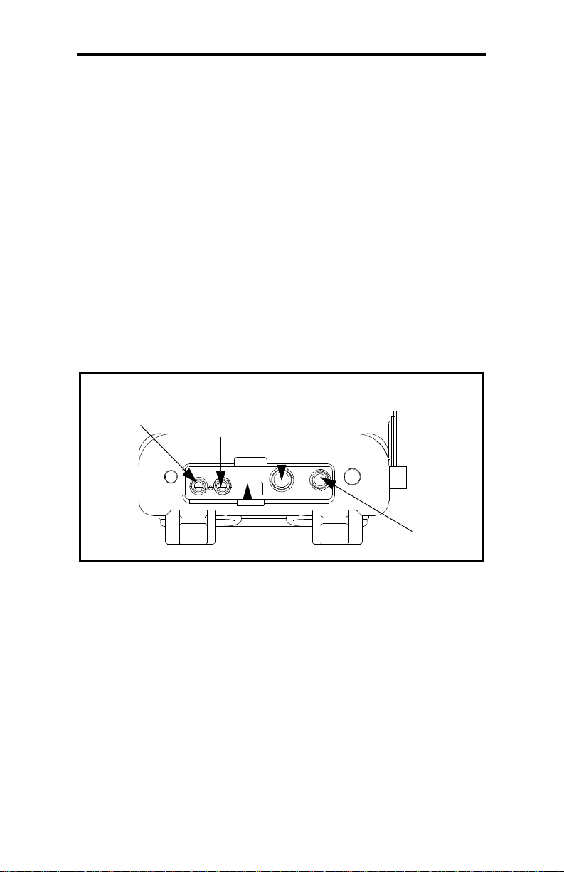
Make all connections to the top of the TransPort unit as shown in
Figure 2-2 below. Please note that you only need to make the
proper transducer connections. The other connections are
required for particular functions, but are not necessary for basic
operation.
Upstream
XDCR
Downstream
Input/Output
(See Table 2-1
on page 2-4)
Infrared
Transceiver
Figure 2-2: Connection Locations
Power
2-2 Initial Setup
Page 19

April 2009
Power Connections
The PT878GC is powered by either a 100-120/200-260 VAC wall
mount plug-in module, or by 5 internal C
-size NiCad high-
s
energy rechargeable batteries or by a pack of 3.0 Ahr NiMH
batteries. (An optional power supplement, part #703-1283, uses 6
AA alkaline batteries.) When you receive the PT878GC, the
batteries are not charged; therefore, to make remote
measurements using the batteries, follow the instructions on
page 2-5 to charge the batteries. In either case, you must connect
the power cord to the appropriate terminal as shown in Figure 2-2
above.
!WARNING!
To ensure the safe operation of the TransPort, you
must install and operate it as described in this manual.
In addition, be sure to follow all applicable safety codes
and regulations for installing electrical equipment in
your area.
Transducer Connections
The transducer cables connect to the TransPort with LEMO®
coaxial type connectors. Each color-coded cable has a collar
labeled UPSTREAM or DOWNSTREAM. Make transducer
cable connections to the top of the flowmeter as shown in Figure
2-2 on the previous page. Transducer installation is discussed
separately in Chapter 3.
Analog Input/Output Connections
The TransPort provides one 0/4-20 mA current output and two
4 to 20-mA analog inputs with switchable 16-V supply for
loop- powered temperature transmitters. Connect the inputs/
outputs using a LEMO
2-2 on the previous page. The pin numbers for the connector and
the color code for the standard input/output cable are shown in
Table 2-1 on the next page.
Initial Setup 2-3
®
multi-pin connector as shown in Figure
Page 20

April 2009
Analog Input/Output Connections (cont.)
Table 2-1: Cable Assembly for Analog Inputs/Outputs
Pin Number Wire Color Description
1 Black Analog Out 1
2 Red 16 V (switched)
3 White Input A (Temperature or Pressure)
4 Yellow Input B (Temperature or Pressure)
5 Green Analog Ground
6 Orange Digital Output
7 Blue Digital Ground
8 Violet Receive Monitor
The Infrared Wireless Interface
The PT878GC comes equipped with an internal infrared
transceiver (see Figure 2-2 on page 2-2) that enables
communication between the meter and other IR devices,
particularly the IR ports or dongles (IR to RS232 adapters) of
Windows
data. The PT878GC was designed for use with products that
comply to the IrDA protocol. For more information on
establishing IR communications between the PT878GC and your
PC, refer to Appendix B.
®
-based PCs. Users can send and receive site and log
2-4 Initial Setup
Page 21
April 2009
Charging and/or Replacing Batteries
The PT878GC comes with self-contained, built-in rechargeable
batteries to support portable operation. For optimum
performance, these batteries require a minimum of maintenance.
Charging the Batteries
When you receive the PT878GC, you will need to initially charge
the batteries. The batteries must be charged up to 8 hours to
receive the maximum charge. When fully charged, the batteries
provide 8 hours of continuous operation. An internal battery
gauge indicates the remaining power in the batteries.
To charge the batteries, simply plug the AC power module cord
into the power jack (shown in Figure 2-2 on page 2-2) and be sure
the battery pack is installed. When the PT878GC is plugged into
line voltage, the internal battery charger automatically charges
the batteries, whether the PT878GC is on or off. If the PT878GC
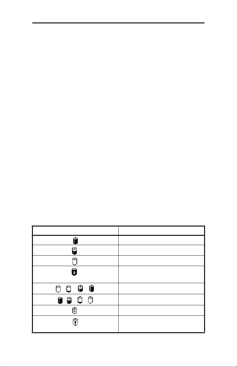
is on, the Battery icon in the upper right corner of the screen
indicates battery status (as shown in Table 2-2 below).
IMPORTANT: For CE compliance, the PT878GC is classified
as a battery-powered device, not to be used with
the AC adaptor.
Table 2-2: Battery Status Icons
Icon Battery Status
Full battery
Partially full battery
Empty battery
Fully charged battery,
connected to AC power
Charging battery
Discharging battery
Failure/missing battery
Notification to check battery
form (see page 7-5)
Initial Setup 2-5
Page 22
April 2009
Replacing the Batteries
Caution!
Replace batteries only with the specified rechargeable
batteries. The battery charges when the unit is off. Do not
attempt to recharge non-rechargeable batteries.
If you need to replace the rechargeable batteries, use 5 C
-size
s
NiCad high energy rechargeable batteries (GE Sensing Part
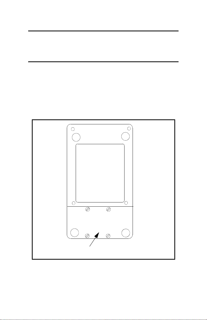
Number 200-058) or 3.0 Ahr NiMH batteries (part number 200-
081). To replace the batteries, remove the rubber boot, open the
panel located on the back of the PT878GC unit, disconnect the
batteries, and replace with new ones (see Figure 2-3 below).
Battery Location
(Behind Panel)
Figure 2-3: Rear View of PT878GC
To further extend the battery power on the PT878GC, the GE
Sensing Part #705-1283 power pack option uses 6 AA alkaline
batteries.
2-6 Initial Setup
Page 23

April 2009
Powering On and Off
To operate the PT878GC, the power cord must be plugged into
line voltage or the battery must be charged as described
previously.
IMPORTANT: For CE compliance, the PT878GC is classified
as a battery-powered device, and cannot be used
with the AC adaptor.
To turn the meter on, press the red button in the upper-right-hand
corner of the keypad. Immediately upon power up the PT878GC
emits a short beep and displays a “PCI Loader” message. It then
validates the instrument programming, and then displays the GE
Sensing logo and the software version and emits a long beep. If
the meter fails any of these tests, contact GE Sensing.
Caution!
If the meter fails the backup battery test, you must send
the unit back to the factory for a battery replacement.
Make sure you keep the NiCad batteries charged until you
are ready to ship the unit back to the factory. Before
shipping, print out all the log and site data, or transfer it to
your PC, as this data will be lost during the service
procedure.
Initial Setup 2-7
Page 24
April 2009
Powering On and Off (cont.)
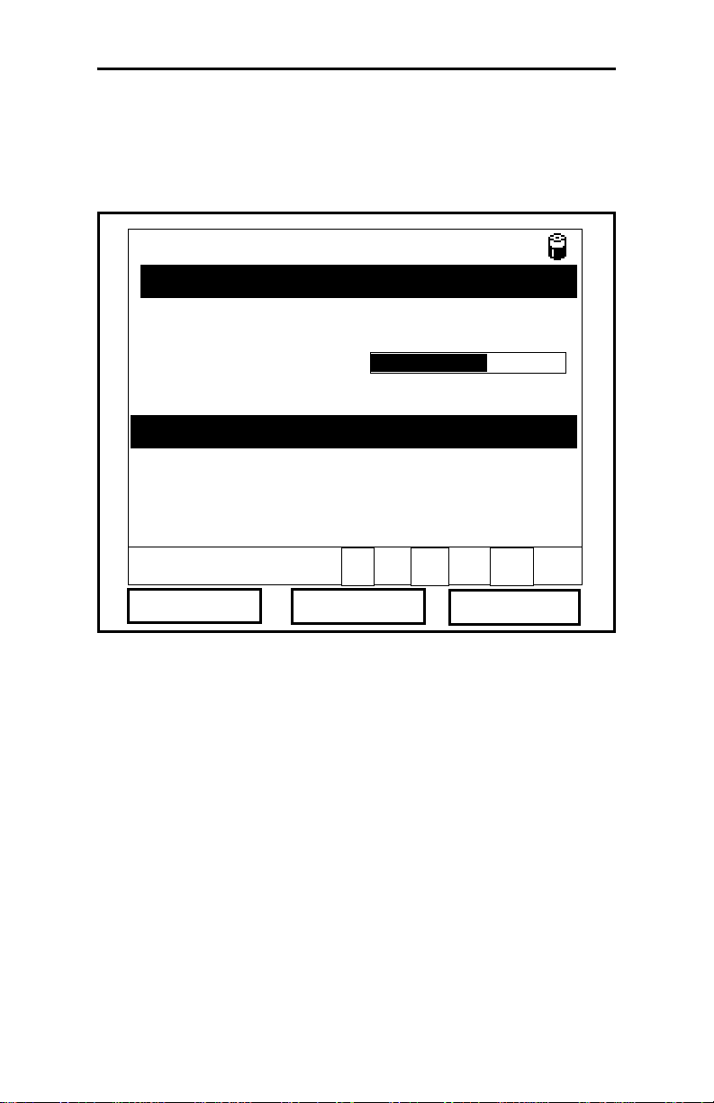
After the meter conducts all the self checks, the screen then
appears similar to the one shown in Figure 2-4 below.
ABC.SIT
Velocity, ft/s
Delta-T, ns
E0: No Errors
Figure 2-4: Screen After Powering On
0.00
0.10
2004/11/30 09:53 AM
Signal, dB
32
Volume, l/s
0.0
2-8 Initial Setup
Page 25
April 2009
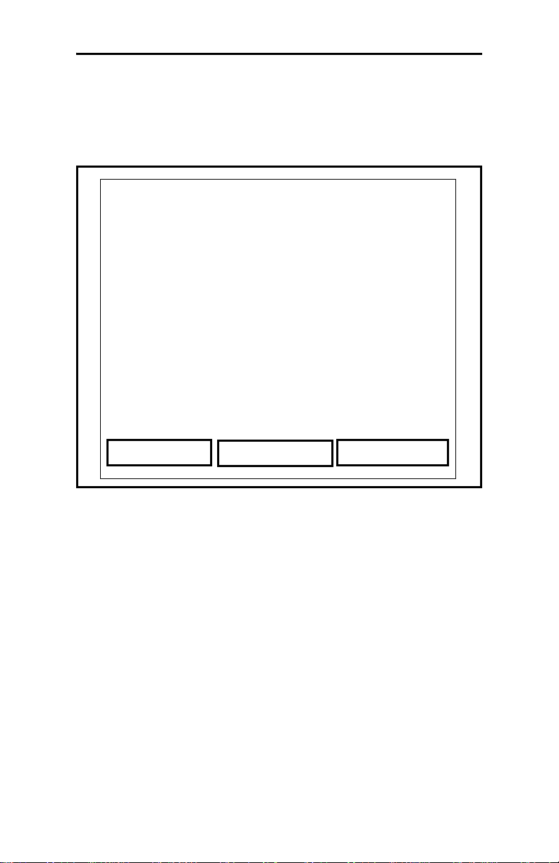
Powering On and Off (cont.)
To turn the PT878GC off, press the red key for 3 seconds. The
screen now appears similar to Figure 2-5 below.
Velocity, ft/s
SHUTDOWN: Meter OFF
Signal, dB
SLEEP: Meter Idle
CANCEL: Resume Operations
Delta-T, ns
Shutdown
Figure 2-5: The Shutdown Menu
Three options are available:
Sleep
Volume, l/s
Resume
• Press [F1] to shut down the PT878GC, turning it completely
off.
• Press [F2] to send the PT878GC into sleep mode. In this mode,
some of the power supplies shut down, but the PT878GC
remains in a standby mode. Users can resume taking
measurements immediately by pressing the power button.
• Press [F3] to cancel the command and return the PT878GC to
normal operation.
If the PT878GC locks up, you can reset it by holding the power
key (the red key in the upper right corner) for 15 seconds.
Initial Setup 2-9
Page 26
April 2009
Using the Screen and Keypad
The essential features for operating the TransPort are the screen
and keypad. Although these features are common on portable
instruments, the PT878GC design offers unique features to
simplify and speed operation.
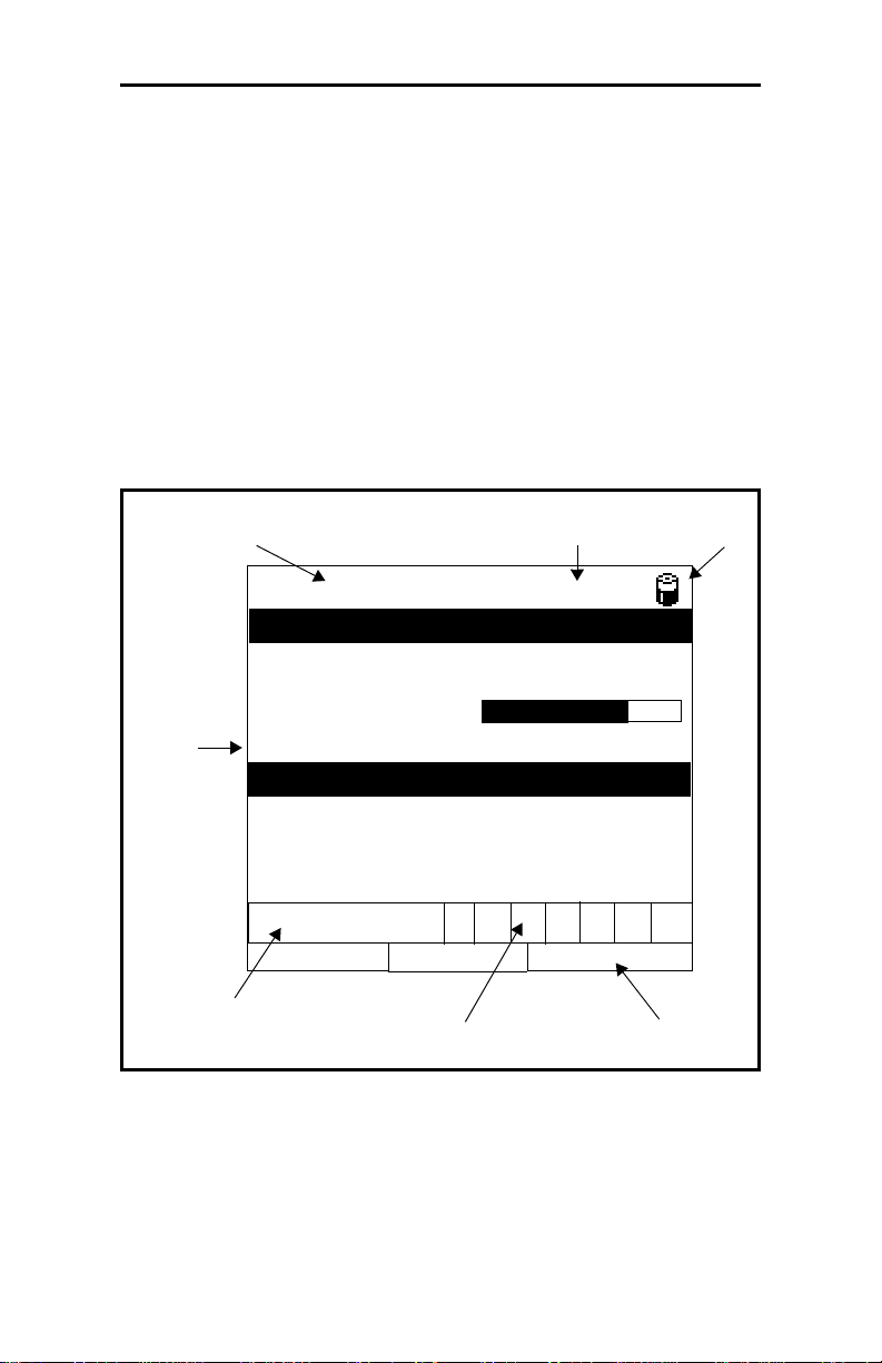
Screen
The primary function of the screen is to display information in
order for you to accurately and easily take measurements. The
TransPort screen consists of seven parts (see Figure 2-6 below).
Current
Site
DEFAULT
Velocity, ft/s
Status Bar
(alternates with
Menu Bar)
2000/11/30 09:53 AM
Signal, dB
Battery
Status
32
0.00
(Work
Area)
Delta-T, ns
0.10
E0: No Errors
Error Messages
Figure 2-6: The PT878GC Screen in Operate Mode
The top line of the screen is the status bar, which normally
displays the time, date and current site. However, when you press
[MENU] (the menu key), the Menu Bar replaces the status bar.
System
Tray
Volume, l/s
0.0
Function Keys
2-10 Initial Setup
Page 27
April 2009
Screen (cont).
The middle of the screen is the work area, which displays the
measured parameters, numeric measurements, and both bar and
line graphs. (When you enter a selection on the Main Menu
discussed in Chapter 4, Programming Site Data, this area
displays menu prompts.) A line at the bottom of the area also
displays error code messages, which are described in more detail
in Chapter 10, Diagnostics and Troubleshooting.
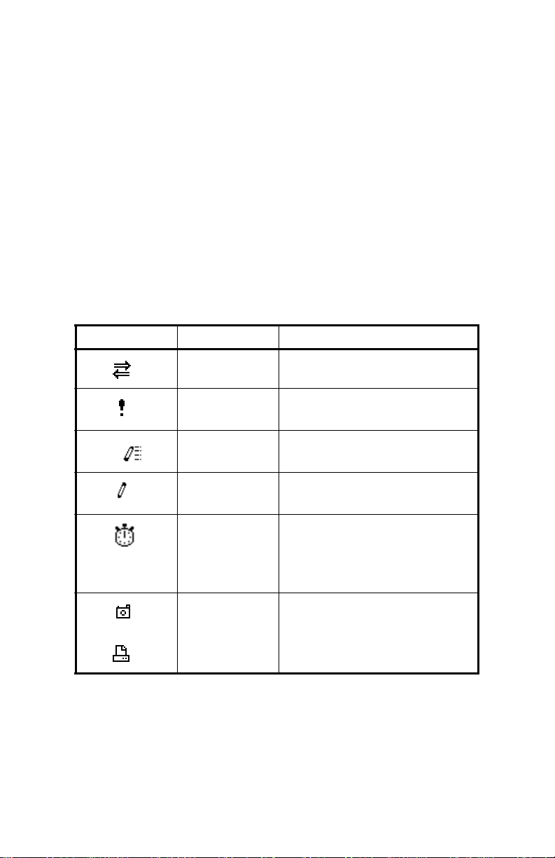
The system tray, shown in Figure 2-6 on page 2-10, displays
icons that indicate meter operations not otherwise shown. Table
2-3 below lists the icons and their meanings.
Table 2-3: Icons in the System Tray
Icon Function Meaning
IR Transfer IR data transfer in progress.
Alert Indicates the meter encoun-
tered an error in operation.
Log Running Indicates a log is running
(marks).
Log Pending Indicates a log is pending (no
marks).
Stopwatch Calibration Gate Operation:
Watch is stopped when the
gate is closed, or runs when it
is open. (See page 3-46.)
Snapshot
(To file)
(To Printer)
Indicates that the Snapshot
function has been activated,
so users can take screen captures (see page 6-23).
The bottom of the screen displays the three feature key options:
F1, F2 and F3. The feature keys have different functions,
depending on the task you are performing.
Initial Setup 2-11
Page 28

April 2009
Keypad
The PT878GC keypad has 25 keys. The functions for each key
are as follows (see Figure 2-7 on the next page):
• 3 function keys ([F1], [F2], [F3]) — enable you to select the
special functions which appear at the bottom of the screen.
• 12 numeric keys (including - and .) — enable you to enter
numeric data.
• 4 arrow keys ([W], [X], [S], [T]) — enable you to move
through the menu options.
• [?] — Help key enables you to access on-line help.
• [MENU] — Menu key enables you to access the Menu Bar.
• [ENTER] — enables you to enter a particular menu, and enters
selected values into the TransPort memory.
• [SEL] — enables you to move between data measurements on
the screen.
• [ESC] — enables you to exit menus or menu options at any
time; cancels numeric entry.
• Red key [ ] turns the power on or off, and toggles the
backlight on or off.
2-12 Initial Setup
Page 29
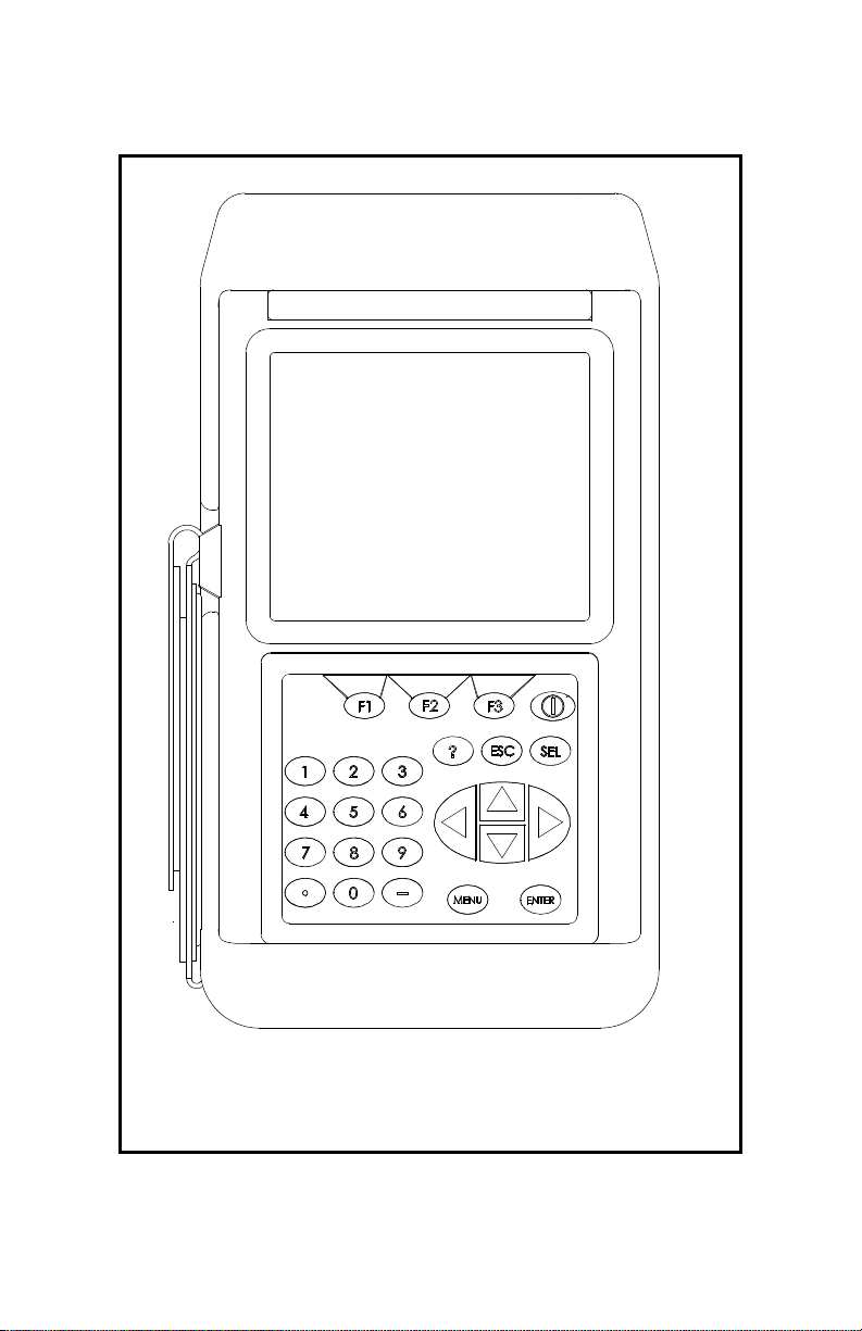
Keypad (cont.)
April 2009
Figure 2-7: The TransPort PT878GC Keypad
Initial Setup 2-13
Page 30
April 2009
Obtaining On-Line Help
The TransPort offers on-line help screens that describe various
features. You can access on-line help at any time by pressing the
[?] key. The screen appears similar to Figure 2-8 below.
Help
Velocity, ft/s
Use the arrows and the enter key to
select from the links below. Press [F2]
to return to the TOC.
Site Menu
Program Menu
Meter Menu
Log Menu
Service Menu
Miscellaneous
About
Back
Figure 2-8: The Main Help Menu
Use the three function keys and the [
navigate to the desired menu, and press
procedure to access the desired topic within the menu. When you
have finished using the Help menu:.
Table of Contents
TOC
Signal, dB
Close
S] and [T] arrow keys to
[ENTER]. Repeat this
• Press [F1], Back, to move back one level.
• Press [F2], TOC, to return to the Table of Contents.
• Press [F3], Close, to return to the previous screen.
2-14 Initial Setup
Page 31

April 2009
Chapter 3
Installing the Dampening Material, Transducers and Fixtures
Since the PT878GC is specifically designed for gas measurement
with clamp-on transducers, it requires the use of specially
designed fixtures and dampening material to maintain the highest
possible measurement accuracy. GE Sensing supplies the CFG
series of fixtures:
• The V1 clamping fixture for pipes with diameters between
0.75 and 1.25 in. (20 to 30 mm).
• The V4 clamping fixture for pipes with diameters between
1.25 and 4 in. (30 to 100 mm).
• The V8 clamping fixture for pipes from 4 to 8 in. (100 to
200 mm).
• The V12 clamping fixture for pipes from 8 to 12 in. (200 to
300 mm).
• The PI clamping fixture for pipes from 12 to 24 in. (300 to
600 mm).
Figure 3-1 on the next page illustrates the V series and PI fixture
assemblies. Complete the steps in the following sections to
position and install the transducers, fixtures and dampening
material.
Installing the Dampening Material, Transducers and Fixtures 3-1
Page 32

April 2009
CFG-V1
CFG-V8
Chain
CFG-V1
CFG-V8
CFG-V4
CFG-V12
Layout Wrap
PI Fixture
Figure 3-1: The V Series and PI Fixtures
Dummy
Block
Strap
Choosing the transducer installation locations on the pipe is an
important aspect of proper flow measurement. Specifications
assume a fully developed flow profile typically requiring 20
diameters upstream and 10 diameters downstream of straight pipe
run. In addition, pipes 2 in. and under require an installation
location with a minimum of 10 ft (3 m) of continuous straight
pipe without flanges, welds or coupling joints.
3-2 Installing the Dampening Material, Transducers and Fixtures
Page 33

April 2009
Application Requirements
Before you begin to use the PT878GC, you should ensure that
your meter can handle the frequencies required for your particular
application. To check the capabilities of your particular
PT878GC, refer to the back label of the PT878GC, shown in
Figure 3-2 below. The gray label below “Communication” lists
the meter type and transducer frequency the PT878GC can
support.
Figure 3-2: PT878GC Back Label
In addition to checking the available frequencies, you should
determine that your application meets the minimum gas pressure
and maximum flow velocity range requirements for optimal
measurements, given the pipe size and pipe thickness. The tables
on the following pages list the minimum pipe sizes, schedules,
and pressures for use with the PT878GC.
Installing the Dampening Material, Transducers and Fixtures 3-3
Page 34

April 2009
Application Requirements (cont.)
•
For air, nitrogen, oxygen or argon, refer to Table 3-1 on the
next page.
• For natural gas, refer to Table 3-2 on page 3-7.
• For steam, refer to Table 3-3 on page 3-9.
1. Find the pipe size of your application
2. Then find the pipe wall thickness of your application.
3. With the pipe size and pipe wall thickness, determine if your
application meets the minimum pressure requirements.
4. Use the same row in the appropriate table to determine the
maximum flow velocity capability of the PT878GC. For
reference, the table provides the recommended number of
traverses and transducer frequency for your application.
Note: All provided data is based on metal pipes; plastic pipes
have a minimum pressure requirement of ambient air or
any non-attenuating gas with a minimum density of 0.074
3
lbs/cf (1.185 kg/m
involving natural gas with sulfur or high carbon dioxide
content, or for applications not listed in the tables.
3-4 Installing the Dampening Material, Transducers and Fixtures
). Consult the factory for applications
Page 35

Table 3-1: PT878GC Installation Requirements for Air, Nitrogen, Oxygen or Argon
Maximum Velocity, ft/s (m/s)
April 2009
Transducer
Pipe Size ANSI (DIN) Pipe Wall Inches (mm)
3/4 (20) <0.07 (1.8) 1 60 (5.1) — — 90 (27.4) — 90 (27.4)
1 (25) <
1 1/2 (40) <
2 (50) <
3 (75) <0.2 1 60 (5.1) 120 (36.6) — 69 (21.0) 46 (14.0) —
4 (100) <0.2 1 60 (5.1) 120 (36.6) — 53 (16.2) 35 (10.7) —
6 (150) <0.2 1 60 (5.1) 90 (27.4) 72 (22.0) 54 (16.5) — —
8 (200) <0.33 (8.4) 0.5 60 (5.1) 80 (24.4) 64 (19.5) 48 (14.6) — —
10 (250) <0.37 (9.4) 0.5 60 (5.1) 70 (21.3) 56 (17.1) 42 (12.8) — —
0.14 (3.6) 1 60 (5.1) — — 90 (27.4) — 90 (27.4)
0.15 (3.8) 1 60 (5.1) — — 90 (27.4) — 57 (17.4)
0.16 (4.1) 1 60 (5.1) 90 (27.4) — 75 (22.9) — 45 (13.7)
<0.22 (5.6) 0.5
<0.24 (6.1) 0.5 60 (5.1)
<
0.34 (8.6) 0.5 180 (13.4)
<
0.68 (17.3) 0.5 300 (21.7)
<0.28 (7.2) 0.5 60 (5.1)
<0.44 (11.2) 0.5 180 (13.4) 90 (27.4) 72 (22.0) 54 (16.5)
<
0.87 (22.1) 0.5 300 (21.7) 90 (27.4) 72 (22.0) 54 (16.5)
<0.50 (12.7) 0.5 180 (13.4) 80 (24.4) 64 (19.5) 48 (14.6)
<
0.88 (22.4) 0.5 300 (21.7) 80 (24.4) 64 (19.5) 48 (14.6)
<0.50 (12.7) 0.5 180 (13.4) 70 (21.3) 56 (17.1) 42 (12.8)
<
1.00 (25.4) 0.5 300 (21.7) 70 (21.3) 56 (17.1) 42 (12.8)
MHz
0.2 200 (13.6) 135 (41.5) 108 (32.9) 81 (24.7)
0.2 600 (40.8) 135 (41.5) 108 (32.9) 81 (24.7)
0.2 1000 (68) 135 (41.5) 108 (32.9) 81 (24.7)
0.2 200 (13.6) 120 (36.6) 96 (29.3) 72 (21.9)
0.2 600 (40.8) 120 (36.6) 96 (29.3) 72 (21.9)
0.2 1000 (68) 120 (36.6) 96 (29.3) 72 (21.9)
0.2 200 (13.6) 105 (32) 84 (25.6) 63 (19.2)
0.2 600 (40.8) 105 (32) 84 (25.6) 63 (19.2)
0.2
Min. Pressure
psig (bar)
1000 (68)
Single
Traverse
105 (32) 84 (25.6) 63 (19.2)
Dual
Traverse
Triple
Traverse
Four
Traverse
Five
Traverse
Installing the Dampening Material, Transducers and Fixtures 3-5
Page 36

Table 3-1: PT878GC Installation Requirements for Air, Nitrogen, Oxygen or Argon (Continued)
Maximum Velocity, ft/s (m/s)
April 2009
Transducer
Pipe Size ANSI (DIN) Pipe Wall Inches (mm)
12 (300) <
14 (350) <0.38 (9.7) 0.2 90 (7.2) 87 (26.5) 70 (21.3) 52 (15.9) — —
16 (400) <
18 (450) <
20 (500) <
24 (600) <
0.38 (9.7) 0.5 60 (5.1) 55 (16.8) 44 (13.4) 33 (10.1) — —
<0.50 (12.7) 0.5 180 (13.4) 55 (16.8) 44 (13.4) 33 (10.1)
<
1.00 (25.4) 0.5 300 (21.7) 55 (16.8) 44 (13.4) 33 (10.1)
<
0.50 (12.7) 0.2 270 (19.6)
0.38 (9.7) 0.2 90 (7.2) 76 (23.2) 61 (18.9) 45 (13.7) — —
0.50 (12.7) 0.2 270 (19.6)
<
0.38 (9.7) 0.2 90 (7.2) 67 (20.4) 54 (16.5) 40 (12.2) — —
<
0.50 (12.7) 0.2 270 (19.6)
0.38 (9.7) 0.2 90 (7.2) 60 (18.3) 48 (14.6) 36 (11.0) — —
<
0.50 (12.7) 0.2 270 (19.6)
0.38 (9.7) 0.2 90 (7.2) 49 (14.9) 39 (11.9) 29 (8.8) — —
0.50 (12.7) 0.2 270 (19.6)
<
MHz
0.2 200 (13.6) 82 (25) 66 (20.1) 49 (14.9)
0.2 600 (40.8) 82 (25) 66 (20.1) 49 (14.9)
0.2 1000 (68) 82 (25) 66 (20.1) 49 (14.9)
Min. Pressure
psig (bar)
Single
Traverse
Dual
Traverse
Triple
Traverse
Four
Traverse
Five
Traverse
Installing the Dampening Material, Transducers and Fixtures 3-6
Page 37

Table 3-2: PT878GC Installation Requirements for Natural Gas
Maximum Velocity, ft/s (m/s)
Pipe Size ANSI
(DIN)
2 (50) <0.16 (4.1) 0.5 200 (14.8) 110 (33.5) 88 (26.8) 66 (20.5)
3 (75) <
4 (100) <
6 (150) <
8 (200) <0.33 (8.4) 0.5 175 (13.1) 100 (30.5) 80 (24.4) 60 (18.3)
10 (250) <0.37 (9.4) 0.5 200 (14.8) 85 (25.9) 68 (20.7) 51 (15.6)
12 (300) <0.38 (9.7) 0.5 200 (14.8) 70 (21.3) 56 (17.1) 42 (12.8)
14 (350) <
16 (400) <
Pipe Wall Inches
(mm)
0.22 (5.6) 0.5 200 (14.8) 120 (36.6) 96 (29.3) 72 (22.0) 48 (14.6)
0.24 (6.1) 0.5 150 (11.4) 120 (36.6) 96 (29.3) 72 (22.0) 48 (14.6)
<
0.34 (8.6) 0.5 400 (28.6)
<
0.68 (17.3) 0.5 800 (56.2)
0.28 (7.2) 0.5 150 (11.4) 120 (36.6) 96 (29.3) 72 (22.0)
<
0.44 (11.2) 0.5 400 (28.6) 120 (36.6) 96 (29.3) 72 (22.0)
<0.87 (22.1) 0.5 800 (56.2) 120 (36.6) 96 (29.3) 72 (22.0)
<
0.50 (12.7) 0.5 400 (28.6) 100 (30.5) 80 (24.4) 60 (18.3)
<0.88 (22.4) 0.5 800 (56.2) 100 (30.5) 80 (24.4) 60 (18.3)
<
0.50 (12.7) 0.5 500 (35.5) 85 (25.9) 68 (20.7) 51 (15.6)
<1.00 (25.4) 0.5 800 (56.2) 85 (25.9) 68 (20.7) 51 (15.6)
<
0.50 (12.7) 0.5 500 (35.5) 70 (21.3) 56 (17.1) 42 (12.8)
1.00 (25.4) 0.5 800 (56.2) 70 (21.3) 56 (17.1) 42 (12.8)
<
0.38 (9.7) 0.2 300 (21.7) 103 (31.4) 77 (23.5) 62 (18.9)
<
0.50 (12.7) 0.2 800 (56.2)
0.38 (9.7) 0.2 300 (21.7) 90 (27.4) 67 (20.4) 54 (16.5)
<
0.50 (12.7) 0.2 800 (56.2)
Transducer
MHz
0.2 250 (17) 180 (54.9) 144 (43.9) 108 (32.9)
0.2 500 (34) 180 (54.9) 144 (43.9) 108 (32.9)
0.2 1000 (68) 180 (54.9) 144 (43.9) 108 (32.9)
0.2 250 (17) 150 (45.7) 120 (36.6) 90 (27.4)
0.2 500 (34) 150 (45.7) 120 (36.6) 90 (27.4)
0.2 1000 (68) 150 (45.7) 120 (36.6) 90 (27.4)
0.2 300 (20.4) 126 (38.4) 102 (31.1) 75 (22.0)
0.2 600 (40.8) 126 (38.4) 109 (31.1) 75 (22.0)
0.2 1200 (81.6) 126 (38.4) 102 (31.1) 75 (22.0)
0.2 300 (20.4) 105 (32) 84 (25.6) 63 (19.2)
0.2 600 (40.8) 105 (32) 84 (25.6) 63 (19.2)
0.2 1200 (81.6) 105 (32) 84 (25.6) 63 (19.2)
Min. Pressure
psig (bar)
Single Traverse Dual Traverse Triple Traverse Four Traverse
April 2009
Installing the Dampening Material, Transducers and Fixtures 3-7
Page 38

Pipe Size ANSI
(DIN)
18 (450) <
20 (500) <
24 (600) <
Table 3-2: PT878GC Installation Requirements for Natural Gas (Continued)
Maximum Velocity, ft/s (m/s)
Pipe Wall Inches
(mm)
0.38 (9.7) 0.2 300 (21.7) 78 (23.8) 59 (18.0) 47 (14.3)
<
0.50 (12.7) 0.2 800 (56.2)
0.38 (9.7) 0.2 300 (21.7) 70 (21.3) 52 (15.9) 42 (12.8)
0.50 (12.7) 0.2 800 (56.2)
<
0.38 (9.7) 0.2 300 (21.7) 56 (17.1) 42 (12.8) 34 (10.4)
<
0.50 (12.7) 0.2 800 (56.2)
Transducer
MHz
Min. Pressure
psig (bar)
Single Traverse Dual Traverse Triple Traverse Four Traverse
April 2009
Installing the Dampening Material, Transducers and Fixtures 3-8
Page 39

April 2009
Table 3-3: PT878GC Installation Requirements for Steam
Maximum
Flow
Velocity
Pipe
Size in.
(mm)
3 (80) <0.22 (5.6) 0.5 110 (8.6) 120 (36.6)
4 (100) <
6 (150) <
8 (200) <
10 (250) <
12 (300) <
Pipe Wall
Inches
(mm)
<
0.3 (7.6) 0.5 200 (14.8)
0.24 (6.1) 0.5 110 (8.6) 120 (36.6)
<
0.34 (8.6) 0.5 200 (14.8)
0.28 (7.2) 0.5 110 (8.6) 120 (36.6)
<
0.44 (11.2) 0.5 200 (14.8)
0.33 (8.4) 0.5 120 (9.3) 100 (30.5)
<
0.5 (12.7) 0.5 200 (14.8)
0.37 (9.4) 0.5 130 (10.0) 85 (25.9)
<
0.5 (12.7) 0.5 200 (14.8)
0.38 (9.7) 0.5 140 (10.7) 70 (21.3)
<
0.5 (12.7) 0.5 200 (14.8)
Transducer
(MHz)
Min.
Pressure
psig (bar)
ft/s (m/s)
Single
Traverse
Installing the Dampening Material, Transducers and Fixtures 3-9
Page 40

April 2009
Preparing the Pipe
1. Locate a transducer measurement point with 20 diameters of
upstream straight run pipe and 10 diameters of downstream
straight run pipe. In addition, the point should be at least 10
diameters from any butt welds or flanges. Keep appropriate
clearance on either side of the pipe for easy transducer
installation:
• 150 mm (6 in.) if you are not using a junction box, or
• 225 mm (9 in.) if you are using a junction box.
In general, transducers are installed 180° apart on opposite sides
of the pipe and in a horizontal plane (at 3 and 9 o’clock). Figure
3-3 below illustrates the desired acoustic signal projection path
for general installation; however, additional pipe surveys may
provide data that can lead to modifications for optimal
installation.
Pipe
Transducer Transducer
Signal Path
End View
Figure 3-3: Desired Projection of Acoustical Signal Path
3-10 Installing the Dampening Material, Transducers and Fixtures
Page 41

April 2009
Performing a Pipe Survey
Finding a location where the pipe is concentric is important for
optimum accuracy and performance. If possible, perform a pipe
survey with an ultrasonic thickness gauge to find the best
location.
2. Clear rust or loose paint and measure the wall thickness at five
points along the pipe axis at 25 mm (1-in.) intervals using an
ultrasonic thickness gauge, as shown in Figure 3-4 below.
Check each point three times and record the mean values. If
the maximum variation between the five points exceeds 0.25
mm (0.010 in.), find another location.
Figure 3-4: Measuring Thickness Along the Pipe Axis
3. Measure the outside diameter (OD) of the pipe using a tape
measure or the supplied layout wrap. Using the entire layout
tape, mark two circumferential lines along the edges of the
wrap, as shown in Figure 3-5 below.
Figure 3-5: Measuring and Marking Circumference Lines
Installing the Dampening Material, Transducers and Fixtures 3-11
Page 42

April 2009
Performing a Pipe Survey (cont.)
4. Now measure the OD and the wall thickness at eight points
along the pipe circumference at 45° intervals (shown in Figure
3-6 below), three times per point, and record the mean values.
OD
1
OD
OD
2
W
W
3
3
W
1
2
W
8
W
7
OD
W
4
4
W
W
6
5
Figure 3-6: Measuring the OD and Pipe Wall Thickness
5. Prepare the pipe for the dampening material by removing any
rust or loose paint and sanding down any rough spots in an
area 12 in. long around the circumference of the pipe. Take
care to preserve the original pipe curvature.
6. At the approximate location of each transducer, prepare an
area 100 mm (4 in.) long by 50 mm (2 in.) wide for CRV type
transducers and 100 mm (4 in.) wide for CRW type
transducers. Remove any paint or rust, and polish the cleared
area, taking care to preserve the original curvature of the pipe.
Note: If the paint is in a thin, smooth layer, removal is not
necessary.
3-12 Installing the Dampening Material, Transducers and Fixtures
Page 43

April 2009
Obtaining the Transducer Spacing
1. Using the measured OD and the pipe wall thickness, program
the PT878GC (discussed in Chapter 4, Programming Site
Data) to determine the required transducer spacing.
2. To determine the PT878GC correction factor, calculate the
mean inside pipe diameter (ID) and the pipe ID at the
transducer locations. Then divide the square of the mean ID
by the square of the ID at the transducer location, as shown in
the equations below, where OD
given point, and W
is the wall thickness at a given point (as
X
shown in Figure 3-6 on the previous page).
is the outside diameter at a
X
mean ID OD
++() 4⁄
=
OD
K
W3W7+()–()OD4W4W8+()–()
3
for non-concentric pipe
W1W5+()–()OD
1
+
Mean ID
------------------------- ---------------------------- --------------=
()
ID at transducer location()
W2W6+()–()
2
2
2
3. Program the value into the PT878GC.
Note: See Chapter 4, Programming Site Data, pages 4-3 to 4-16,
for more details on programming.
Based on the pipe OD, proceed to the appropriate section:
• If the pipe is < 12” (300 mm), see the section Installing the V
Series Clamping Fixture and Transducers on the next page.
• If the pipe is > 12” (300 mm), go to Installing the PI Fixture
and Transducers on page 3-18.
Installing the Dampening Material, Transducers and Fixtures 3-13
Page 44

April 2009
Installing the V Series Clamping Fixture and Transducers
Note: A complete installation involves the clamping fixture,
transducers and dampening material. To apply
dampening material, refer to Installing Dampening
Material on page 3-25.
To install the V Series clamping fixture and transducers, complete
the following steps:
Installing the Fixture
1. Position the half of the clamping fixture with the threaded
rods around the pipe, as shown in Figure 3-7 below. Orient the
fixture in the 3 o’clock position on a horizontal pipe.
2. Position the mating half of the fixture over the threaded rods
in the 9 o’clock position. Figure 3-7 below shows the two
mounted halves.
Note: If you are using a V4 fixture with a 1.5 to 2-in. pipe, GE
Sensing suggests removing the set screws and the
mounting bracket, rotating them and the transducer yoke
180°, and replacing the bracket, yoke and screws for a
more secure fit.
Figure 3-7: Mounting the Two Halves of the Fixture
3-14 Installing the Dampening Material, Transducers and Fixtures
Page 45

April 2009
Installing the Fixture (cont.)
The two fixture halves have measuring scales; ensure that the
scales are on the same side of the fixture, so that both zeros start
at the same origin, as shown in Figure 3-8 below.
0 1 2 3
0 1 2 3
Figure 3-8: Fixture with Scale Origins Properly Aligned
3. Install the four nuts onto the threaded rods with the convex
side of the nut facing the fixture. Hand tighten the nuts on
each V block evenly, as shown in Figure 3-9 below. Do not
use a cross tightening pattern on the four installation nuts.
Figure 3-9: Installing Nuts onto the Fixture
Installing the Dampening Material, Transducers and Fixtures 3-15
Page 46

April 2009
Installing the Transducers
1. Apply a bead of couplant 6 mm (0.25 in.) wide along the
entire length of each transducer face, as shown in Figure 3-10
below.
Figure 3-10: Couplant on Transducer Face
Note: Do not slide the transducer with couplant along the
surface of the pipe when mounting the transducer.
2. Set the first mounting block (either left edge or right edge) at a
convenient number on the scale, such as 1 in. or 1 cm. Install
the first transducer with the BNC connector pointing away
from the center of the V block fixture. Hold down the
transducer mounting screw onto the insert, which in turn
applies pressure to the transducer. Use a handtight grip to set
the transducer in contact with the pipe, as shown in Figure 311 below. Use a wrench to tighten the backing nut to prevent
loosening due to vibration and thermal expansion.
IMPORTANT: Do not use a wrench or pliers on the screw.
Figure 3-11: Installing the First Transducer
3-16 Installing the Dampening Material, Transducers and Fixtures
Page 47

April 2009
Installing the Transducers (cont.)
3. Slide the second mounting block to the calculated spacing
plus the initial scale number selected for the first mounting
block. For example:
a. Initial convenient number for the first mounting block =
5 cm or 2 in.
b. Spacing as calculated by the PT878GC = 0.5 in. or 12.5
mm
c. Second mounting block final location = 1 + 0.5 in. = 1.5 in.
or 1 cm + 1.25 cm = 2.25 cm
The overall spacing between yokes should be left edge to left
edge, or right edge to right edge. Figure 3-12 below shows typical
positioning.
S
S
Figure 3-12: Top View of V4 Fixture
with Both Transducers
4. In a similar manner, install the second transducer as shown in
Figure 3-12 above.
Installing the Dampening Material, Transducers and Fixtures 3-17
Page 48

April 2009
Installing the PI Fixture and Transducers
The PI clamping fixture holds transducers on pipes from 8 to 24
in. in diameter. It comes with either a chain or strap, depending
on the selection made with the initial order from GE Sensing. To
install the fixture and transducers, complete the following steps:
Surveying the Pipe
1. Measure the pipe circumference to an accuracy of ±2 mm
(±1/16 in.)
IMPORTANT: Do not
2. Tightly wrap the layout tape once around the entire pipe and
line up the edges. Using the tape as a template guide for
marks, mark scribe lines around the entire circumference of
the pipe, as shown in Figure 3-13 below.
Figure 3-13: Marking Circumferential Lines on the Pipe
3. Line up the zero scale of the layout tape at the desired location
of the first transducer. (For a typical installation, this point
will be the 3 o’clock position on a horizontal pipe.) Mark each
of the two circumferential lines at the zero point. Connect
each of these marks using a straight edge (for example, the
edge of the layout tape) as shown in Figure 3-14 on the next
page.
use a calculated value or a nominal value
for the circumference.
3-18 Installing the Dampening Material, Transducers and Fixtures
Page 49

April 2009
Surveying the Pipe (cont.)
Figure 3-14: Marking the 3 o’Clock Position
4. To find the coinciding point on the opposite site of the pipe
(180° away from each other), divide the measured
circumference by 2 and measure this distance along the
circumferential lines from the zero point, as shown in Figure
3-15 below. Place marks on both sides of the circumferential
lines made with the layout tape and connect the marks.
Figure 3-15: Marking the 9 o’Clock Position
Make sure to take the 180° point measurement from both over the
top of the pipe and under the bottom of the pipe (on a horizontal
pipe) to ensure reciprocity of the installation. Figure 3-16 on the
next page shows the appropriate way to measure the 180° point.
Installing the Dampening Material, Transducers and Fixtures 3-19
Page 50

April 2009
Surveying the Pipe (cont.)
Figure 3-16: Measuring the 180° Point
from Top and Bottom
3-20 Installing the Dampening Material, Transducers and Fixtures
Page 51

April 2009
Installing the First Bracket with a Chain or Strap
The following steps describe how to install the PI fixture with a
supplied chain or strap.
1. Carefully wrap the chain or strap around the pipe, taking care
not to twist it.
2. Loosen the wing nuts up to the end of the J-hooks. Then hook
the chain into the tightest links and loosely hand tighten the
wing nuts. If you are using a strap, insert the J-hook into the
smaller round hole on the strap.
3. Line up one edge of the CFG-PI holder bracket with the origin
scribe line and fully tighten the chain or strap (see Figures
3-17 and 3-18 below).
Origin Scribe Line
Front Edge of
Holder Bracket
Figure 3-17: Lining up the First Bracket
4. Install the transducer dummy block to verify the
circumferential and axial location. Center the indicator line on
the block to line up with the scribed mark (see Figure 3-18
below).
Figure 3-18: Positioning the CFG-PI Holder Bracket
5. Loosen the transducer hold-down screw and tighten the J-
hooks on the clamping fixture. Be sure the bracket has not
moved from its position.
Installing the Dampening Material, Transducers and Fixtures 3-21
Page 52

April 2009
Installing the Second Bracket with a Chain or Strap
Note: The following step requires the transducer spacing
discussed on page 3-7.
1. Measure the spacing from the zero point (the point of
circumferential origin). Mark the spacing point with a
crosshair on the opposite side of the pipe, 180° from the zero
point (as shown in Figure 3-19 below).
Figure 3-19: Measuring and Marking Spacing
2. Carefully wrap the chain or strap around the pipe, taking care
not to twist it.
3. Loosen the wing nuts up to the end of the J-hooks. Then hook
the chain into the tightest links and firmly hand tighten the
wing nuts.
4. Line up the other edge of the CFG-PI holder bracket with the
scribe line and tighten the chain or strap, as shown in Figure
3-20 below.
Mark on Opposite
Scribe Line
Rear Edge of
Second Block
Figure 3-20: Lining up the Rear Edge of the Bracket with the
180° Scribe Line
3-22 Installing the Dampening Material, Transducers and Fixtures
Page 53

April 2009
Installing the Second Bracket (cont.)
The spacing should now appear similar to that shown in Figure
3-21 below.
S
Figure 3-21: The Installed CFG-PI Fixture,
with Calculated Spacing
Installing the Transducers
1. Check to be sure the second CFG-PI holder bracket is
correctly positioned.
2. Apply a bead of CPL-16 couplant 6 mm (0.25 in.) wide on
each transducer face. (See Figure 3-22 below.)
Figure 3-22: Couplant on Transducer Face
Installing the Dampening Material, Transducers and Fixtures 3-23
Page 54

April 2009
Installing the Second Bracket (cont.)
Note: Do not slide the transducer with couplant along the
surface of the pipe when mounting the transducer.
3. With one hand, mount one transducer into the PI fixture. With
the other hand, tighten the transducer hold down screw,
gradually pushing the transducer down to the pipe surface.
Use a wrench to tighten the backing nut to prevent loosening
due to vibration and thermal expansion.
IMPORTANT: Do not use pliers or a wrench on the thumbscrew.
4. Repeat step 3 for the other transducer.
3-24 Installing the Dampening Material, Transducers and Fixtures
Page 55

April 2009
Installing Dampening Material
GE Sensing strongly recommends applying DMP dampening
material in ALL clamp-on applications to help eliminate short
circuit noise. The material comes in two versions:
• The DMP-1 self-adhesive sheet for applications up to
150°F (66°C). The material comes as two 9.5-in. (24 cm)
wide sheets cut in sufficient length to cover the pipe
circumference plus an additional tenth of a circumference.
The material can be cut with a utility knife, and comes with
a paper backing that is removed before installation.
• The DMP-3 is a clay-like compound for all temperature
applications. If the temperature is over 150°F, the PDJ pipe
dampening jacket (available from GE Sensing with
preapplied DMP-3) must be used with the material.
At a minimum, you should consider applying dampening material
if you have any of the following conditions:
• The distance from the nearest butt weld or pipe flange is
less than 10 ft (3 m);
• The pipe size is under 4 in. (100 mm) diameter and the gas
pressure is 200 psig (14 barg) or lower;
• The pipe is deformed,
• The pipe is old, with a history of scaling or rust,
• The pipe experiences condensation on the outside.
Note: Consult a GE Sensing flowmeter applications engineer or
sales engineer if you have any questions regarding
dampening material.
Installing the Dampening Material, Transducers and Fixtures 3-25
Page 56

April 2009
Installing DMP-1 Dampening Material
1. Be sure the CFG-V clamping fixture is installed on the pipe
with the transducers as described in the section Installing the
V Series Clamping Fixture and Transducers on page 3-14.
With a marker, mark scribe lines on the inside edges of the
brackets onto the pipe. These lines indicate where to apply the
material. (One 9.5-in. roll fits between the brackets.)
2. Remove the fixture and transducers.
3. Use a dry towel or rag and thoroughly dry the pipe.
4. Unroll the DMP-1 material and cut off a length equal to the
circumference. Peel the paper backing off the cut portion.
IMPORTANT: The DMP-1 material will only adhere to the pipe
correctly if the pipe is completely dry. To adhere
properly, the material must also be at a
temperature above 50°F (10°C).
5. Before more atmospheric condensation can occur on the
outside of the pipe, roll the DMP-1 dampening material once
around the pipe, following the scribe marks that represent the
inside edge of the fixture, as shown in Figure 3-23 below.
Figure 3-23: DMP-1 Dampening Material
Wrapped Around Pipe
6. Reinstall the fixture, and make sure the spacing is set
correctly. Loosely mount the transducers on top of the
dampening material, using the correct spacing.
3-26 Installing the Dampening Material, Transducers and Fixtures
Page 57

April 2009
Installing DMP-1 Dampening Material with CFG-V
Series Fixtures (cont.)
7. With a marker, trace around the transducer footprint, as shown
in Figure 3-24 below.
Figure 3-24: DMP-1 Material with
Transducer Footprint Traced
8. Remove the fixture and transducers. Then use a utility knife to
cut out the area under the transducer footprint, and peel the cut
material off the pipe, as shown in Figure 3-25 below.
Note: Remove excess dampening material as soon as possible,
before it adheres to the pipe and becomes difficult to
remove.
Figure 3-25: DMP-1 Material with
Transducer Footprint Cut Out
9. To remove any residual adhesive, clean the cut-out area with a
rag or a piece of sandpaper, or use varnish remover.
10. Reinstall the fixture and transducers on the pipe.
Installing the Dampening Material, Transducers and Fixtures 3-27
Page 58

April 2009
Installing DMP-1 Dampening Material with CFG-V
Series Fixtures (cont.)
11. Lay the second strip of dampening material flat. Then cut the
strip into two pieces, each 4.5-in. (12 cm) wide.
12. Wrap each of these strips around the pipe on the outside edge
of the clamping fixture, one upstream and one downstream.
The completed dampening material installation should appear
similar to Figure 3-26 below.
Figure 3-26: Completed DMP-1 Installation
3-28 Installing the Dampening Material, Transducers and Fixtures
Page 59

April 2009
Installing DMP-1 Dampening Material with PI Fixture
1. Be sure the PI clamping fixture is installed onto the pipe with
the transducers as described in the section Installing the PI
Fixture and Transducers on page 3-18.
2. Approximate the axial distance from one transducer face to
the other transducer face, as shown in Figure 3-27 below.
Figure 3-27: Distance Between Transducer Faces
3. Lay the first strip of dampening material flat. Cut a strip to a
width equal to the distance between transducer faces (the
distance illustrated in Figure 3-27 above).
4. Wrap this strip around the pipe in the space between the
transducers.
5. Lay the second strip of dampening material flat. Then cut the
strip into two pieces, each 4.5-in. (12 cm) wide.
6. Wrap each of these strips around the pipe on the outside edge
of the clamping fixture, one upstream and one downstream.
The completed installation should appear similar to Figure
3-28 on the next page.
Installing the Dampening Material, Transducers and Fixtures 3-29
Page 60

April 2009
Installing DMP-1 Dampening Material with PI Fixture
(cont.)
Figure 3-28: Completed DMP-1 Installation
3-30 Installing the Dampening Material, Transducers and Fixtures
Page 61

April 2009
Installing DMP-3 Compound with All Fixtures
1. Be sure the fixture and transducers are installed on the pipe as
described in the previous sections of this chapter.
2. Remove the fixture and transducers, but be sure to mark the
approximate area of installation.
3. Remove any loose paint or rust with a file or emery cloth, as
shown in Figure 3-29a below. If the finish is mirror-smooth,
roughen the surface.
(a)
(b)
Figure 3-29: Filing (a) and Degreasing (b) the Pipe Surface
4. While wearing appropriate gloves, degrease the surface as
shown in Figure 3-29b above.
5. Place a piece of the DMP-3 material on top of the pipe (Figure
3-30a), and use the palm of the hand to press it onto the pipe
(see Figure 3-30b below).
(a)
(b)
Figure 3-30: Applying the DMP-3 Material
Installing the Dampening Material, Transducers and Fixtures 3-31
Page 62

April 2009
Installing DMP-3 Compound with All Fixtures (cont.)
6. Spread the DMP-3 material so that it covers the whole area
under the fixture to a thickness of about 0.25 in. (6.4 mm), as
shown in Figure 3-31a below.
(a)
(b)
Figure 3-31: Spreading the DMP-3 (a) and
Reinstalling the Fixture (b)
7. Position the transducer yokes to the correct spacing and
reinstall the fixture around, but not on, the DMP-3 material, as
shown in Figure 3-31b above.
8. Remove the DMP-3 material from the transducer locations
(Figure 3-32a below).
(a)
(b)
Figure 3-32: Clearing DMP-3 from the Transducer Location
(a) and Installing the Transducers (b)
9. Apply the couplant to the transducers, and install the
transducers onto the pipe.
Note: If the measurement point is near a flange or weld, apply
DMP-3 between that structure and the fixture as well.
3-32 Installing the Dampening Material, Transducers and Fixtures
Page 63

April 2009
Installing the PDJ Dampening Jacket
If the pipe temperature is over 150°F, you must use the PDJ pipe
dampening jacket with preapplied DMP-3. As the dampening
material dries out over several hours after installation, its
effectiveness increases. The jacket is available in standard pipe
sizes from 4 to 12 in. (100 to 300 mm).
1. Remove any insulation from the installation area, as well as
any loose paint, rust and high spots from the pipe.
2. Remove the backing paper from the inside of the pipe
dampening jacket (shown in Figure 3-33 below).
Figure 3-33: The PDJ Pipe Dampening Jacket
3. Install the jacket on the pipe as shown in Figure 3-34 below.
Tighten the clamping screws so that some fluid drips from the
bottom of the jacket.
Figure 3-34: Installation of a PDJ Jacket
Installing the Dampening Material, Transducers and Fixtures 3-33
Page 64

April 2009
Installing the PDJ Dampening Jacket (cont.)
!WARNING!
The pipe and the dripping fluid will cause severe burns
upon contact with bare skin. Also, be sure not to inhale
the fumes generated during the DMP-3 curing cycle.
4. Install the fixture over the jacket, adjusting the spacing to
match the prestamped transducer holes and PT878GC spacing
calculations.
5. Apply a thin bead of CPL-16 couplant. Spread it in a thin layer
about 6 mm (0.25 in.) wide on each transducer face.
6. Install the transducers into the yokes, and tighten the holddown screws until the couplant touches the pipe.
7. If you wish, reinstall insulation over the pipe, making sure that
the yokes and junction boxes protrude through the insulation.
8. Wait 15 min. for the couplant to skin and finger-tighten the
transducer hold-down screws. Do not use pliers or any other
tools.
9. Using a wrench, tighten the transducer hold-down screw
backing nuts to prevent loosening due to vibration and thermal
expansion.
3-34 Installing the Dampening Material, Transducers and Fixtures
Page 65

April 2009
Chapter 4
Programming Site Data
On the PT878GC, a Program Menu (part of the Main Menu)
enables you to enter information that is specific to each site:
• Transducer types and paths
• Pipe materials and linings
• Fluid types
• Standard volume and mass flow parameters
• Skan/Measure parameters
• Analog input and output parameters
• Digital output parameters
• User functions
• Correction factors
For immediate operation, the PT878GC requires only transducer,
pipe and fluid data. However, additional information allows you
to tailor measurements to your application. Once you have
entered this data, you can save it in files and recall these files for
later use. The PT878GC can store up to 1 MB of data in the meter
at any one time. But through the infrared link, users can store an
unlimited number of sites on a PC, and then upload the sites as
they are needed.
This chapter covers entering:
• The Program Menu
• Transducer, pipe, and fluid parameters
• Input/output and other setup parameters
• User functions.
Programming Site Data 4-1
Page 66

April 2009
Entering the Program Menu
To enter the Program Menu, press the [MENU] key at the lower
right of the PT878GC keypad. The Menu Bar replaces the Status
Bar at the top of the screen. Press the [
scroll from the Site Menu to the Program Menu. At the Program
Menu, press
below. While following the programming instructions, refer to
Figure A-2 on page A-2 of Appendix A, Menu Maps
[ENTER]. The screen appears similar to Figure 4-1
Site Program Meter Logging Service
Transducer
Vel
ocity, ft/s
Pipe
Lining
Fluid
Path
0.00
Std Vol/Mass Flow
Skan/Measure
Delta
-T, ns
Analog Input
Analog Output
Digital Output
0.10
User Functions
E0: No Errors
Correction Factors
X] arrow key once to
Signal, dB
32
Volume, l/s
0.0
Figure 4-1: The Program Menu
To scroll to a particular option, press the [
until you reach the option. Then press
window.
When entering parameters in an option, press:
T]or [S] arrow keys
[ENTER] to open the option
• The [T] key to step through the available parameters
• The [S] key to scroll back to a previously entered parameter
• The [F2] key (Cancel) or the [ESC] key to exit an option at any
time and return to Operate Mode without changing the
parameters.
Note: On certain text box parameters, you can use the numeric
keys to enter a desired value. You can then use the [
[T] keys to change the value, if necessary.
4-2 Programming Site Data
S] or
Page 67

April 2009
Entering Transducer Parameters
To enter the Transducer option, scroll to the Transducer entry on
the Program Menu and press
to Figure 4-2 below. To step through each parameter (or reach a
particular parameter), press the [
page A-3 of Appendix A, Menu Maps
Note: Refer to Chapter 3 for additional information about
clamp-on gas transducers and fixture configurations.
.
[ENTER]. The screen appears similar
T] key. Refer to Figure A-3 on
Transducer/Pipe
Transducer
Type: Wetted
Frequency
Figure 4-2: The Transducer Option Window
1. The first prompt asks you to select whether you are using a
wetted or a clamp-on transducer.
a. Use the [
b. Press
W] and [X] keys to scroll between the two types.
[ENTER] or [SEL] to confirm the choice.
Pipe
Transducer
2.00
Wedge Ang
Wedge Tmp
Wedge SS
Cancel
Lining Path
Fluid
Clamp-on
Special
MHz
Tw
50
25
1219.2
°
°C
14
m/s
µs
OK
IMPORTANT: While wetted transducers are listed as a choice,
the PT878GC is designed for use with Shear
wave clamp-on transducers. Consult GE before
selecting wetted transducers.
Programming Site Data 4-3
Page 68

April 2009
Entering Transducer Parameters (cont.)
Note: The choices made earlier in the Transducer and Pipe
options determine the prompts available later. If the
PT878GC does not scroll to a particular parameter, it is
not necessary for that transducer or pipe type.
2. The next prompt asks you to enter the transducer number, or to
specify that you are using a special application transducer.
a. From the Type prompt, press the [
Transducer prompt, and press
b. A drop-down list of transducer numbers opens, if you have
selected clamp-on in the previous prompt. Press the [
S] keys to scroll to the appropriate number, or scroll to
[
“Special” for a special application transducer. To speed
scrolling, you can press the [
page, or the [
c. Press
The program now varies, depending on whether you have
selected preprogrammed or special transducers.
[ENTER] to confirm your selection.
W] key to scroll up by a page.
T] key to reach the
[ENTER].
X] key to scroll down by a
• If you have selected a transducer from the list of
preprogrammed shear clamp-on transducers (#301 to 315), the
PT878GC comes programmed with the needed parameters.
You only need to enter the wedge temperature.
a. From the Wedge Angle prompt, press the [
the Wedge Temperature prompt, and press
b. Use the numeric keys to enter the wedge temperature (in
degrees) and press
[ENTER].
T] key to reach
[ENTER].
T] or
Note: For highest accuracy, program the wedge temperature to
the average of the gas and ambient temperatures. For
example, if the gas temperature is 350°, the wedge
temperature is (350+70)/2 = 210°F.
Pressing the [
at the top. Go to page 4-7 to continue programming.
T] key thus returns the meter to the Transducer tab
• However, if you have selected a special application transducer,
turn to the next page.
4-4 Programming Site Data
Page 69

April 2009
Parameters for Special Transducers
3. The prompt asks for the transducer frequency, to transmit a
voltage at a rate to which the transducer can respond.
a. From the Transducer prompt, press the [
the Frequency prompt, and press
T] key to reach
[ENTER].
b. A drop-down list of five frequencies opens, ranging from
0.25 to 4.00 MHz. Scroll to the frequency of your
transducers, and press
[ENTER].
4. The next prompt asks for Tw, the time delay. This parameter is
actually the time the transducer signal spends travelling
through the transducer and cable. The PT878GC calculates the
flow rate by subtracting the time of the upstream and
downstream signals, so the time delay must be subtracted out
for an accurate measurement. GE Sensing supplies the time
delay on a data sheet inside the transducer case.
a. From the Frequency prompt, press the [
Tw prompt, and press
[ENTER].
X] key to reach the
b. Use the numeric keys to enter the GE Sensing-supplied
time delay and press
[ENTER].
5. When calculating the flow rate, the PT878GC must take into
account the wedge angle, the angle of the ultrasonic
transmission.
a. From the Tw prompt, press the [
Wedge Angle prompt, and press
T] key to reach the
[ENTER].
b. Use the numeric keys to enter the GE Sensing-supplied
wedge angle (in degrees) and press
[ENTER].
6. The PT878GC must also take into account the wedge
temperature.
a. From the Wedge Angle prompt, press the [
the Wedge Temperature prompt, and press
T] key to reach
[ENTER].
b. Use the numeric keys to enter the wedge temperature (in
degrees) and press
Programming Site Data 4-5
[ENTER].
Page 70

April 2009
Parameters for Special Transducers (cont.)
Note: If the transducer is installed on a pipe that is at a different
temperature than the ambient temperature, the wedge
temperature is the average of the pipe temperature and
the ambient temperature.
7. Finally, the PT878GC requires the wedge sound speed.
a. From the Wedge Temp prompt, press the [
the Wedge SS prompt, and press
b. Use the numeric keys to enter the GE Sensing-supplied
wedge sound speed (in ft/sec or m/sec) and press
Pressing the [T] key returns the meter to the Transducer tab at
the top.
[ENTER].
T] key to reach
[ENTER].
• To confirm the entries and return to Operate Mode, press [F3]
(OK).
• To leave the window without confirming the entries and return
to Operate Mode, press
[F2] (Cancel) or the [ESC] key.
4-6 Programming Site Data
Page 71

April 2009
Entering Pipe Parameters
To enter the Pipe option, scroll to the Pipe entry on the Program
Menu and press
scroll back up to the Transducer tab and press the [
to reach the Pipe window and press
similar to Figure 4-3 below. To step through each parameter,
press the [
A, Menu Maps.
Note: Refer to the brochure Sound Speeds and Pipe Size Data
(914-004) for additional information about pipe sizes and
sound speeds.
[ENTER]. (From the Transducer window, you can
X] arrow key
[ENTER].) The screen appears
T] key. Refer to Figure A-4 on page A-4 of Appendix
Transducer/Pipe
Transducer
Material
SndSpeed
OD, mm
5
5
Nominal
Figure 4-3: The Pipe Option Window
Pipe
Lining
Other
600.3
OD x PI, mm
15.708
Schedule
Cancel
m/s
Schedule
Fluid
Wall, mm
2
ANSI
OK
Path
Programming Site Data 4-7
Page 72

April 2009
Entering Pipe Parameters (cont.)
1. The first prompt asks you to select the pipe material.
a. Press
[ENTER] to enter the material prompt.
b. A drop-down list of materials opens. Table 4-1 below lists
the available preprogrammed materials on the list. Press
T] or [S] keys to scroll to the appropriate material,
the [
or scroll to “Other” for a material not on the list. You can
press the [
X] key to scroll down by a page, or the [W] key
to scroll up by a page.
Table 4-1: Preprogrammed Pipe Materials
Pipe Material
Category Specific Material
Al - Aluminum Rolled
Brass None
Cu - Copper Annealed or Rolled
CuNi - Copper/Nickel 70% Cu 30% Ni or
90% Cu 10% Ni
Glass Pyrex, Flint, or Crown
Gold Hard-drawn
Inconel None
Iron Armco, Ductile, Cast, Electrolytic
Monel None
Nickel None
Plastic Nylon, Polyethylene, Polypropy-
lene, PVC (CPVC), or Acrylic
Steel Carbon Steel or Stainless Steel
Tin Rolled
Titanium None
Tungsten Annealed, Carbide, Drawn
Zinc Rolled
Other Any material
c. Press
4-8 Programming Site Data
[ENTER] to confirm the choice.
Page 73

April 2009
Entering Pipe Parameters (cont.)
2. At this point, the program follows one of two paths:
a. If you have selected a preprogrammed material, the
PT878GC automatically supplies the correct sound speed,
and proceeds to step 3.
b. If you have selected “Other,” the meter prompts you to
enter the sound speed. Use the numeric keys to type the
known sound speed in the text box, and press
confirm the choice.
3. At this point, two alternatives are available. At the Diameter
prompt, the meter asks for the pipe outside diameter and
thickness. But if you have selected certain pipe materials
(carbon or stainless steel, cast iron, PVC and CPVC), you
have the option of entering the pipe dimensions by a
standardized schedule. Once you enter the nominal pipe size
and schedule identification, the PT878GC determines the OD
and wall thickness from an internal table.
[ENTER] to
If you select a material that uses the Diameter alternative:
a. You must select from two choices, outside diameter or
circumference.
• The prompt moves to the OD (outside diameter) text box.
Type the pipe OD (in mm or in.) into the text box, and press
[ENTER] to confirm the choice, or
• Move the prompt to the OD X PI (circumference) text box.
Type the circumference (in mm or in.) into the box, and
[ENTER] to confirm your choice.
press
b. In either case, the next prompt asks for the wall thickness.
Type the value (in mm or in.) into the box, and press
[ENTER] to confirm your choice
Note: The measurement units shown depend on the choices you
have made in the English/Metric window of the Meter
menu.
Programming Site Data 4-9
Page 74

April 2009
Entering Pipe Parameters (cont.)
If you select a material that has the Schedule option:
a. The prompt asks if you wish to apply DIN (the DIN
schedule). Press
box. (If you do not select the DIN option, the prompt
moves to the OD text box, and you enter the parameters for
the Diameter alternative as discussed on the previous
page.)
Note: If you have selected English units in the Meter Menu (as
discussed on page 7-3), the schedules appear as ANSI.
[ENTER] to select (or deselect) the DIN
b. Press the [
Nominal pipe size drop-down menu. Press
the menu. Scroll to the desired pipe size, and press
to confirm your choice.
c. Press the [
drop-down menu. Press
the desired schedule (5S, 10S, 40S or 80S), and press
[ENTER] to confirm the choice.
After entering either diameter or schedule settings, pressing the
S] key returns the meter to the Pipe Material prompt.
[
W] key twice to move the prompt to the
[ENTER] to open
[ENTER]
X] key to move the prompt to the Schedule
[ENTER] to open the menu. Scroll to
• To confirm the entries and return to Operate mode, press [F3]
(OK).
• To leave the window without confirming the entries and return
to Operate mode, press
[F2] (Cancel) or the [ESC] key.
• To return to the Pipe tab and scroll to other windows, press the
[
S] key.
4-10 Programming Site Data
Page 75

April 2009
Entering Pipe Lining Parameters
To enter the Lining option, scroll to the Lining entry on the
Program Menu and press
can scroll back up to the Pipe tab and press the [X] arrow key to
reach the Lining window, and press
similar to Figure 4-4 below. To step through each parameter,
press the [T] key. While programming, refer to Figure A-3 on
page A-3 of Appendix A, Menu Maps.
Note: The Lining option is only available for clamp-on
transducers.
[ENTER]. (From the Pipe window, you
[ENTER].) The screen appears
Transducer/Pipe
Transducer Pipe
Material
Sound Speed
Thickness
Lining
Tar/Epoxy
2000
0
Fluid
m/s
mm
Path
Cancel OK
Figure 4-4: The Pipe Lining Window
1. The PT878GC first prompts you to select the pipe lining
material.
a. Press
[ENTER] to open the drop-down list of lining
materials.
b. Scroll to the appropriate material. If you do not see your
lining material on the list, select “Other.”
c. Press
Programming Site Data 4-11
[ENTER] to confirm your choice.
Page 76

April 2009
Entering Pipe Lining Parameters (cont.)
Note: If your pipe lining is not on the drop-down list, consult GE
Sensing for further information.
2. The program follows one of two paths:
a. If you have selected a preprogrammed material, the
PT878GC automatically supplies the correct sound speed,
and you proceed to step 3.
b. If you have selected “Other,” the meter prompts you to
enter the sound speed. Press
to type the known sound speed in the text box, and press
[ENTER] to confirm the choice.
[ENTER]. Use the numeric keys
3. The meter now asks for the lining thickness. Press
Use the numeric keys to enter the known value in the text box,
and press
Pressing the [
[ENTER] to confirm your entry.
T] key returns the meter to the Lining tab.
[ENTER].
• To confirm the entries and return to Operate mode, press [F3]
(OK).
• To leave the window without confirming the entries, press [F2]
(Cancel) or the
[ESC] key.
• To scroll to other windows, press the [W] or [X] key.
4-12 Programming Site Data
Page 77

April 2009
Entering Fluid Types and Speeds
To access the Fluid option, scroll to the Fluid entry on the
Program Menu and press
Transducer/Pipe form, press the [X] arrow key to reach the Fluid
window, and press
4-5 below. To step through each parameter, press the [T] key.
Refer to Figure A-3 on page A-3 of Appendix A, Menu Maps.
[ENTER]. (If you are already in the
[ENTER].) The screen appears similar to Figure
Transducer/Pipe
Fluid
Transducer
Figure 4-5: The Fluid Type Window
1. The first prompt asks for the gas type.
a. Press
[ENTER] to open the drop-down menu. The following
choices are available:
Pipe
Fluid Type
Sound Speed
Lining
Cancel OK
Other
345.75
• Other
Fluid
Path
m/s
• Air
• Natural Gas
• Steam
Programming Site Data 4-13
Page 78

April 2009
Entering Fluid Types and Speeds (cont.)
b. Scroll to the appropriate entry. If you do not see your fluid
on the list, select “Other.”
c. Press
If you have selected a preprogrammed gas, the PT878GC supplies
the sound speed. Pressing the [T] key returns you to the Fluid
tab. However, if you have selected “Other,” the PT878GC
prompts you to enter the sound speed.
a. Press
b. Use the numeric keys to enter the known sound speed.
c. Press
Pressing the [T] key returns you to the Fluid prompt.
[ENTER] to confirm your selection.
[ENTER] to open the text box.
[ENTER] to confirm the selection.
• To confirm the entries and return to Operate mode, press [F3]
(OK).
• To leave the window without confirming the entries and return
to Operate mode, press
[F2] (Cancel) or the [ESC] key.
4-14 Programming Site Data
Page 79

April 2009
Entering the Signal Path Parameters
To enter the Path option, scroll to the Path entry on the Program
Menu and press
back up to the Lining tab and press the [X] arrow key to reach the
Path window, and press
Figure 4-6 below. To step through each parameter, press the [T]
key. Refer to Figure A-3 on page A-3 of Appendix A, Menu
Maps.
[ENTER]. (From the Lining window, you can scroll
[ENTER].) The screen appears similar to
Transducer/Pipe
Transducer
Path Length
Axial Length
Pipe Lining
Traverses
Spacing
Cancel
248.92
203.2
1
90
Fluid
mm
mm
mm
Path
OK
Figure 4-6: The Signal Path Window
Note: The Path Length and Axial Length parameters are not
available for clamp-on transducers.
Programming Site Data 4-15
Page 80

April 2009
Path Parameters for Clamp-On Transducers
The PT878GC path menu includes two parameters for clamp-on
transducers:
• Traverses
• Spacing
1. The PT878GC first prompts for traverses, the number of times
the ultrasonic signal crosses the pipe.
a. Press
b. Scroll to the appropriate number.
c. Press
2. The next prompt displays the spacing of the transducers, as
calculated from the information entered.
a. Record this number and use it to space the transducers.
b. If necessary, you can overwrite the spacing to match the
Note: GE Sensing does not recommend using a spacing other
[ENTER] to open the drop-down list of traverse
numbers.
[ENTER] to confirm the entry.
(Use Chapter 3 to assist in installing transducers on the
pipe.) Press the [T] key to scroll to the next parameter.
actual physical spacing of the transducers. (Do not change
the spacing by more than ±10% from that calculated by the
meter.) Press
desired value, and press
enter an invalid entry, the PT878GC rejects the entry and
displays an error message.
than the one calculated by the PT878GC.
[ENTER]. Use the numeric keys to enter the
[ENTER] to confirm the entry. If you
After you enter the spacing, pressing the [
prompt to the Traverses box, and then to the Path tab at the top of
the screen.
S] key returns the
• To confirm the entries and return to Operate mode, press [F3]
(OK).
• To leave the window without confirming the entries and return
to Operate mode, press
4-16 Programming Site Data
[F2] (Cancel) or the [ESC] key.
Page 81

April 2009
Entering the Standard Volume/ Mass Flow Parameters
The Standard Volume/Mass Flow option enables you to correct
standard volumetric units for pressure and temperature, as well as
to disable or enable mass flow. To enter this option, scroll to the
Std Vol/Mass Flow entry on the Program Menu and press
The screen appears similar to Figure 4-7 below. To step through
each parameter, press the [T] key. Refer to Figure A-5 on
page A-5 of Appendix A, Menu Maps.
Std Vol/Mass Flow
[ENTER].
Settings
Standard_Volume
Atmospheric Pressure Bars
Figure 4-7: The Standard Volume Option Window
1. The first prompt asks if you want to disable or enable the
Standard Volume option.
a. Use the [
radio button.
Inputs
Base Pressure
Base Temperature
l
W] and [X] keys to scroll to the appropriate
Mass Flow
Cancel
DisabledEnabled
1.0
1.0
15.5
Bars
°C
OK
b. Press
Note: If you select “Disabled,” you cannot select any other
Programming Site Data 4-17
[ENTER] to confirm your selection.
prompts in this window.
Page 82

April 2009
Entering the Standard Volume Parameters
(cont.)
2. The next prompt asks for the base pressure.
a. Press
b. Use the numeric keys to enter the known pressure.
c. Press
3. The next prompt asks for the atmospheric pressure.
a. Press
b. Use the numeric keys to enter the local atmospheric
c. Press
4. The final prompt in this window asks for the base temperature
(in degrees F or C).
a. Press
b. Use the numeric keys to enter the known temperature.
c. Press
[ENTER] to enter the text box.
[ENTER] to confirm the entry.
[ENTER] to enter the text box.
pressure.
[ENTER] to confirm the entry.
[ENTER] to enter the text box.
[ENTER] to confirm the entry.
Pressing the [
prompt, and then to the Settings tab.
S] key returns the meter to the Standard Volume
• To confirm the entries and return to Operate mode, press [F3]
(OK).
• To leave the window without confirming the entries and return
to Operate mode, press
4-18 Programming Site Data
[F2] (Cancel) or the [ESC] key.
Page 83

April 2009
Entering Inputs in the Standard Volume Option
To enter input parameters in the Standard Volume/Mass Flow
option, return to the Settings tab at the top of the Standard
Volume window. Press the [X] arrow key and
Inputs window. The screen appears similar to Figure 4-8 below.
To step through each parameter, press the [T] key.
Std Vol/Mass Flow
[ENTER] to open the
Settings Inputs
Mass Flow
Pressure
Pressure
Fixed
1.01
Bars
Active
Input #
A
Temperature
Active
Input #
B
Te mp
Fixed
15.5
°C
Cancel OK
Figure 4-8: The Inputs Tab in the
Standard Volume/Mass Flow Option
1. The first prompt asks if the pressure is fixed or active.
a. Use the [
W] and [X] keys to scroll to the appropriate
radio button.
b. Press
Programming Site Data 4-19
[ENTER] to confirm your selection.
Page 84

April 2009
Entering Inputs in the Standard Volume Option (cont.)
2. The next prompt appears if you have selected a fixed pressure.
The PT878GC asks for the fixed pressure value.
a. Press
[ENTER] to open the text box.
b. Use the numeric keys to enter the known pressure.
c. Press
[ENTER] to confirm the entry.
3. Whether you have selected a fixed or an active supply, the
PT878GC asks for the desired input.
a. From the Pressure text box, press the [X] arrow key to
reach the Input # menu.
b. Press
[ENTER] to open the drop-down menu.
c. Scroll to Input A or B.
d. Press
[ENTER] to confirm the entry.
4. The next prompt asks if the temperature is fixed or active.
a. Use the [
W] and [X] keys to scroll to the appropriate
radio button.
b. Press
[ENTER] to confirm your selection.
5. The next prompt appears if you have selected a fixed
temperature. The PT878GC asks for the fixed temperature
value.
a. Press
[ENTER] to open the text box.
b. Use the numeric keys to enter the known temperature (in
degrees C or F), and press
[ENTER] to confirm the entry.
6. Whether you have selected a fixed or an active temperature,
the PT878GC asks for the desired input.
a. Press
[ENTER] to open the drop-down menu.
b. Scroll to Input A or B.
c. Press
4-20 Programming Site Data
[ENTER] to confirm the entry.
Page 85

April 2009
Entering Inputs in the Standard Volume Option (cont.)
Note: If you have switched both active inputs to #A (or to #B),
the PT878GC automatically switches one input to the
other letter. This change ensures that only one analog
input is assigned to one measurement type.
Pressing the [T] key returns the meter to the Inputs tab.
• To confirm the entries and return to Operate Mode, press [F3]
(OK).
• To leave the window without confirming the entries and return
to Operate mode, press
[F2] (Cancel) or the [ESC] key.
Programming Site Data 4-21
Page 86

April 2009
Entering Mass Flow Parameters
To enter mass flow parameters in the Standard Volume/Mass
Flow option, press the [X] arrow key until you reach the Mass
Flow tab, and then press
The screen appears similar to Figure 4-9 below. To step through
each parameter, press the [T] key.
[ENTER] to open the Mass Flow window.
Std Vol/Mass Flow
Settings Inputs
Mass Flow
Mass Flow
Enabled
Calculation Method
Static Density
Saturated Steam Input
Static Density
1.02305
Disabled
Temperature
Kgs/m3
Cancel OK
Figure 4-9: The Mass Flow Tab in the Standard Volume/Mass
Flow Option
1. The first prompt asks if you want to disable or enable the
Mass Flow option.
a. Use the [
W] and [X] keys to scroll to the appropriate
radio button.
b. Press
[ENTER] to confirm your selection.
Note: If you select “Disabled,” you cannot select any other
prompt in this window.
4-22 Programming Site Data
Page 87

April 2009
Entering Mass Flow Parameters (cont.)
2. If you have enabled Mass Flow, the next prompt asks for the
calculation method. Three options are available: static density,
saturated steam, and steam.
a. Press
b. Scroll to the appropriate method for your application.
c. Press
[ENTER] to open the drop-down menu.
[ENTER] to confirm the entry.
• If you select Saturated Steam:
The prompt asks for the Saturated Steam input. Press
[ENTER], scroll to either Temperature or Pressure, and press
[ENTER].
• If you select Static Density:
The prompt asks for the Static Density value. Press
to open the text box, enter the appropriate value, and press
[ENTER] to confirm the entry.
Pressing the [
and then to the Mass Flow tab.
S] key returns the meter to the Mass Flow prompt,
[ENTER]
• To confirm the entries and return to Operate mode, press [F3]
(OK).
• To leave the window without confirming the entries and return
to Operate mode, press
[F2] (Cancel) or the [ESC] key.
Programming Site Data 4-23
Page 88

April 2009
Entering Skan/Measure Parameters
IMPORTANT: Do not change the Skan/Measure parameters
unless recommended by GE Sensing.
If you select one of the Skan/Measure modes in the Measurement
mode window in the Signal Setup option (see page 9-24), the
PT878GC requires you to set up the appropriate parameters. You
can enter this option in either of two ways:
• From the Program Menu, scroll to the Skan/Measure option
and press
[ENTER], or
• From the Measurement Mode window (page 8-13), select the
method, press
Measure Setup prompt, and press
In either case, the screen appears similar to Figure 4-10 below. To
step through each parameter, press the [T] key. Refer to
Figure A-6 on page A-6 of Appendix A, Menu Maps.
[ENTER], press the [T] key to reach the Skan/
[ENTER] again.
Skan/Measure
All
Figure 4-10: The Skan/Measure Setup Option
4-24 Programming Site Data
Integrate
% of Peak
SkanT Offset
M>S Switch
Limit Meas Delta
Count
Advanced
Cancel
Correlate
80
12.6
µs
5
µs
µs
4
OK
Page 89

April 2009
Entering Skan/Measure Parameters (cont.)
1. The first prompt asks for the Percent of Peak, which is used to
calculate the transit times and Delta-T. The default value is 80,
and values from 1 to 100 are acceptable.
a. Press
[ENTER] to enter the text box.
b. Use the numeric keys to enter the recommended value.
c. Press
[ENTER] to confirm the entry.
2. The next prompt asks for Skan-T Offset, a time measurement
offset that compensates for any shift resulting from crosscorrelation. The default value is 12.6 µsec, and values from
-500 to 500 µsec are acceptable.
a. Press
[ENTER] to enter the text box.
b. Use the numeric keys to enter the recommended value.
c. Press
[ENTER] to confirm the entry.
3. The next prompt, M>S Switch, causes the meter to switch
from Skan to Measure Mode when Delta-T is less than the
M>S Switch value. The default value is 5.0 µsec and values
from 0 to 250 µsec are acceptable.
Note: Do not change this value without consulting GE Sensing.
If you wish to use Skan only, set the M/S Switch to a value
of 0.
a. Press
[ENTER] to enter the text box.
b. Use the numeric keys to enter the recommended value.
c. Press
[ENTER] to confirm the entry.
4. The program now asks if you wish to Limit the Measurement
Delta. (The default is unchecked or off.)
a. Press
[ENTER] to enter the text box.
b. Use the numeric keys to enter the recommended value in
µsec.
c. Press
Programming Site Data 4-25
[ENTER] to confirm the entry.
Page 90

April 2009
Entering Skan/Measure Parameters (cont.)
Pressing the [T] key highlights the Advanced prompt. To enter
advanced parameters for the Skan/Measure modes, press
The screen now appears similar to Figure 4-11 below. In each
case, to enter a value:
[ENTER].
a. Press
[ENTER] to enter the text box.
b. Use the numeric keys to enter the value.
c. Press
[ENTER] to confirm the entry.
Advanced Signal Setup
Skan/Meas
# of Shifts
T Window
R Window
Meas Window
Noise Window Width
Noise Window Offset
3
1
10
10
3
0
Cancel OK
cycles
cycles
cycles
cycles
Figure 4-11: The Advanced Skan/Measure Window
5. The first prompt, the number of shifts, corresponds to the
actual number of transmits per cycle (the number of signals
added together in one direction to produce an averaged signal
for one interrogation of the fluid). It need only be changed if
the environment is very noisy or the acoustic signal is weak.
The default value is 3 and values from 0 to 10 are acceptable.
4-26 Programming Site Data
Page 91

April 2009
Entering Skan/Measure Parameters (cont.)
6. The next prompt enables you to reset the size of the transmit
window. Normally, the PT878GC calculates the size of both
transmit and receive windows based on pipe size and fluid
sound speed. However, for special diagnostic purposes, it may
sometimes be necessary to reset the window size. The default
value is 1 and values from 0 to 1,000 are acceptable.
7. The next prompt enables you to reset the size of the receive
window for diagnostic purposes. The default value is 10 and
values from 0 to 300 are acceptable.
8. The Meas Window prompt allows you to customize the width
of the measurement window. While this window is normally
10 cycles wide, the option allows you to customize the width
from 1 to 60.
Pressing the [T] key returns the meter to the # Shifts entry.
• To confirm the entries and return to Operate mode, press [F3]
(OK).
• To leave the window without confirming the entries and return
to Operate mode, press
Programming Site Data 4-27
[F2] (Cancel) or the [ESC] key.
Page 92

April 2009
Entering Skan/Measure Integrate Parameters
To enter parameters for the Skan/Measure Integrate mode in the
Skan/Measure option, press the [X] arrow key once to reach the
Integrate tab. Then press
which appears similar to Figure 4-12 below.
[ENTER] to open the Integrate window,
Skan/Measure
All
Integrate
A Divisor
Noise Level
Count
Correlate
2.5
5
%
Measure Only
Cancel OK
Figure 4-12: The Integrate Window in the Skan/Measure
Option
1. The first prompt, A Divisor, is used in the calculation of the
Measure Mode integrated threshold level and is not normally
changed. The default value for this parameter is 2.5, and
values from 0.1 to 10 are acceptable.
a. Press
[ENTER] to enter the text box.
b. Use the numeric keys to enter the recommended value.
c. Press
[ENTER] to confirm the entry.
2. Next, enter the Noise Level (-Offset % of Peak) from 0 to
95%, and press
a. Press
[ENT]. (The default value is 20%.)
[ENTER] to enter the text box.
b. Use the numeric keys to enter the recommended value.
c. Press
4-28 Programming Site Data
[ENTER] to confirm the entry.
Page 93

April 2009
Entering Skan/Integrate Parameters (cont.)
3. If you wish to use Measure Times only (instead of both Skan
and Measure times), press
prompt. (You can also press
Pressing the [T] key returns the meter to the A Divisor entry, and
pressing the [
S] key returns the meter to the Integrate tab.
[ENTER] at the Measure Only
[ENTER] to deselect the prompt.)
• To confirm the entries and return to Operate mode, press [F3]
(OK).
• To leave the window without confirming the entries and return
to Operate mode, press
[F2] (Cancel) or the [ESC] key.
Programming Site Data 4-29
Page 94

April 2009
Entering Skan/Measure Count Parameters
To open the Skan/Measure Count window in the Skan/Measure
option, press the [X] arrow key twice (from the All tab) to reach
the Count tab. Press
Figure 4-13 below.
[ENTER], and the screen appears similar to
Skan/Measure
All
Integrate
Cycle Number
Cycle Width
Noise Level
Measure Only
Minimum Noise Level
Count
Correlate
8
20
SNR Test
1
%
%
5
Low SNR Error Level 7
Cancel OK
Figure 4-13: The Count Window in the
Skan/Measure Option
1. The first prompt asks for the Cycle Number that triggers the
count from 1 to 100. (The default number is 1.)
a. Press
[ENTER] to enter the text box.
b. Use the numeric keys to enter the recommended number.
c. Press
[ENTER] to confirm the entry.
2. The meter now asks for the Cycle Width (# of cycle count
samples, minimum width of valid cycle).
a. Press
[ENTER] to enter the text box.
b. Use the numeric keys to enter the recommended value.
c. Press
4-30 Programming Site Data
[ENTER] to confirm the entry.
Page 95

April 2009
Entering Skan/Measure Count Parameters (cont.)
3. The next prompt asks for the percentage of Noise Level.
a. Press
[ENTER] to enter the text box.
b. Use the numeric keys to enter the recommended value.
c. Press
[ENTER] to confirm the entry.
4. If you wish to select (or deselect) Measure Times only
(instead of both Skan and Measure times), press
[ENTER] at the
Measure Only prompt.
5. If you wish to select (or deselect) a SNR (signal-to-noise
ratio) test, press the [X] key to highlight the SNR Test prompt
and press
[ENTER].
a. If you have selected SNR Test, the next prompt asks for the
Minimum Noise Level. Press
recommended value, and press
[ENTER], type in the
[ENTER] to confirm the
entry.
b. The final prompt asks for the Low SNR Error Limit. (The
default is 7.) Press
value, and press
[ENTER], type in the recommended
[ENTER] to confirm the entry.
Pressing the [T] key returns the meter to the Cycle Number
entry, and pressing the [
S] key returns the meter to the Count
tab.
• To confirm the entries and return to Operate mode, press [F3]
(OK).
• To leave the window without confirming the entries and return
to Operate mode, press
Programming Site Data 4-31
[F2] (Cancel) or the [ESC] key.
Page 96

April 2009
Entering Skan/Correlation Parameters
To open the Skan/Correlation window in the Skan/Measure
option, press the [X] arrow key three times (from the All tab) to
reach the Correlate tab, and press
similar to Figure 4-14 below.
Skan/Measure
[ENTER]. The screen appears
All
Min Threshold
Max Threshold
Percent Peak
Integrate
Count
Correlate
-100
100
-40
%
%
%
Measure Only
Cancel OK
Figure 4-14: The Correlate Window in the Skan/Measure
Option
To identify the peak of the received signal, the PT878GC uses the
“Threshold” method, in which the peak is identified as the point
where the signal crosses a threshold that is a percentage of the
maximum signal detected.
1. The first prompt, Min Threshold, asks for the minimum
percentage of peak used to measure transit time.
a. Press
[ENTER] to enter the text box.
b. Use the numeric keys to enter the recommended value.
c. Press
4-32 Programming Site Data
[ENTER] to confirm the entry.
Page 97

April 2009
Entering Skan/Correlation Parameters (cont.)
2. Repeat step 1 to enter the maximum percentage of peak.
3. The next prompt asks for the Percent of Peak, which is used to
calculate the transit times and Delta-T.
a. Press
b. Use the numeric keys to enter the desired value.
c. Press
4. To select (or deselect) Measure Times only (instead of both
Skan and Measure times), press
prompt.
Pressing the [T] key returns the meter to the Min Threshold
entry, and pressing the [
tab.
[ENTER] to enter the text box.
[ENTER] to confirm the entry.
[ENTER] at the Measure Only
S] key returns the meter to the Correlate
• To confirm the entries and return to Operate mode, press [F3]
(OK).
• To leave the window without confirming the entries and return
to Operate mode, press
[F2] (Cancel) or the [ESC] key.
Programming Site Data 4-33
Page 98

April 2009
Entering Analog Inputs
The Analog Inputs option enables you to specify parameters for
general purpose or standard volume inputs. To enter the Analog
Inputs option, scroll to the Analog Inputs entry on the Program
Menu and press
Volume Option (see page 4-18), the screen appears similar to
Figure 4-15 below. To step through each parameter, press the [T]
key. Refer to Figure A-6 on page A-6 of Appendix A, Menu
Maps.
Entering General-Purpose Analog Inputs
Input A Input B
[ENTER]. If you have not enabled the Standard
Analog Input
Function
General Purpose
Label
Units
Zero
Span
100
0
Psia
Cancel OK
Figure 4-15: The Analog Inputs Option Window
1. The first prompt asks you to select whether the desired
function is off or general purpose.
a. Press
[ENTER] to open the drop-down menu.
b. Scroll to the desired response.
c. Press
[ENTER] to confirm your selection.
Note: If you select “Off,” you cannot select any other prompts in
this window.
4-34 Programming Site Data
Page 99

April 2009
Entering General-Purpose Analog Inputs (cont.)
2. The next prompt asks you to create a label for the input. The
label corresponds to the measurement type (i.e., velocity or
temperature), while the units symbol corresponds to the
measurement units (i.e., feet/sec or degrees F).
a. Press
[ENTER] to open the text creation window, which
appears similar to Figure 4-16 below.
A B C D E F G H I J
K L M N O P Q R S T
U V W X Y Z 0 1 2 3
4 5 6 7 8 9 . , “ ‘
= < >
Delete
Cancel
OK
Figure 4-16: The Text Creation Window
b. Use the four arrow keys to scroll to the desired letter or
symbol, and press
Note: Pressing
[SEL] causes the screen to alternate between a
[ENTER] to add the letter to the label.
set of upper-case (capital) letters, a set of lower-case
letters, and a set of symbols. Use all three screens to
create a desired label.
c. Repeat this procedure for each letter or symbol you wish to
add to the label. If you wish to delete a letter, press
[F1]
(Delete) to erase each letter or symbol, from right to left on
the label. (The label window can display up to 14
characters.)
d. When you have completed the label, press
confirm the label, or
[F2] (Cancel) to leave the window
[F3] (OK) to
without adding the label.
Programming Site Data 4-35
Page 100

April 2009
Entering General-Purpose Analog Inputs (cont.)
3. The next prompt asks for the Units Symbol.
a. Press
[ENTER] to reopen the text creation window.
b. Repeat the procedure used for the Label (on the previous
page) to create the Units Symbol.
c. When you have completed the entry, press
confirm the symbol, or
[F2] (Cancel) to leave the window
[F3] (OK) to
without adding the symbol. If you confirm the symbol, the
Units symbol will appear to the right of the zero and span
text boxes.
4. The next prompt asks for the zero input value.
a. Press
[ENTER] to enter the text box.
b. Use the numeric keys to enter the desired value.
c. Press
[ENTER] to confirm the entry.
5. The final prompt asks for the span input value.
a. Press
[ENTER] to enter the text box.
b. Use the numeric keys to enter the desired value.
c. Press
[ENTER] to confirm the entry.
You have completed entering data for general-purpose inputs.
4-36 Programming Site Data
 Loading...