

Page 1

GE
Measurement & Control
PANAFLOW Z1G:
TIGHT GAS WELLHEAD FLOWRATE
MEASUREMENT
For over 30 years, Panametrics owmeters from GE have proven to be the most reliable solution
for challenging gas ow measurement applications. With proven reliability in are gas, stack gas
and steam, GE’s robust transducer technology is ideal for shale gas and coal seam gas wellhead
applications. In short, GE oers the most reliable ultrasonic meter available, plus local service when
and where you need it.
Flare Gas Flow Measurement: The Ultimate Reliability Test
As a pioneer in ultrasonic transit-time ow measurement, Panametrics distinguished its owmeters by
providing reliable gas ow measurement solutions in extremely harsh applications for the past three
decades. Joining the GE Measurement & Controls group in 2004, provided Panametrics with greater
technical reach, and improved greater resource access, resulting in even greater improvements in
ultrasonic transducer design.
How can you be sure that your owmeter will operate reliably in something as challenging as a shale
gas or coal seam methane wellhead application? Choose a owmeter with a proven track record
of reliable operation in an even more dicult application! Since the development of the world’s rst
ultrasonic owmeter for are gas applications in 1980, GE has been the market leader with over
7,000 installations in an application with gas compositions from 2 g/mol to over 120 g/mol, ow
velocities from 0.1 ft/s to over 394 ft/s, and process temperatures from -160oC to 280°C. The world’s
best performance and vast experience in this dicult application translates directly to outstanding
performance in shale gas and coal seam gas ow measurement.
Flowmeter Reliability Starts With A Reliable Transducer
Reliable ultrasonic ow measurement starts with transducer sound wave signal amplitude and signal to
noise ratio (SNR). In shale gas or coal seam gas applications, these signals can be weakened from sulfur,
coal ne or other condensate build up on the transducer face.
imagination at work
1
Page 2
Solids accumulating on the transducer face act like a
muer and attenuate the signal. As this scaling continues
to accumulate, the transmitted and received ultrasonic
signals continue to degrade, which results in reduced signal
amplitude and degraded SNR. The pictures below are
from two dierent locations of working transducers, pulled
for routine maintenance. The better the SNR and signal
amplitude exhibited under ideal conditions, the better the
transducer will be able to hold up under harsh conditions.
GE’s transducers are driven by an industry high 170 volt
pulse, providing very high signal amplitude. This high power
requires an explosion proof enclosure design, (Ex d rating)
to meet hazardous area certication requirements. Other
transducer designs, meet hazardous area certication
requirements by simply being intrinsically safe (Ex ia).
Although intrinsically safe transducers work well in
clean applications, they are not well suited to handle the
challenges presented in shale or coal seam wellhead gas
ow measurement, due to the high level of condensates in
the gas stream
It’s not complicated. Less power means less signal.
Fluctuating Well Head Flow Rates Require
High Turndown Ratio Metering
Throughout the lifecycle of a coal seam well, ow rates
can uctuate considerably as a result of changing well
conditions, therefore it is important to select a meter with
a high turndown ratio to assure a long service life. The
Panaow Z1G has a turndown ratio of 240:1, measuring
ow rates as low as from 0.5 ft/s and as high as 120 ft/s,
and under pressure conditions that are below atmospheric.
Under higher ow conditions, background noise degrades
SNR, however, with the industry highest signal amplitude,
GE transducers overcome this obstacle.
When you have millions of dollars invested in a shale gas
or coal-seam gas well, you need reliable, accurate gas ow
measurement. As the gas moves from the well distribution
network to the gas gathering station for processing,
understanding well production trends is a critical element
in natural gas production eciency. As wells age, gas
production levels are unstable. This information is a critical
part of knowing which wells are producing with maximum
eciency, and which are in need of maintenance.
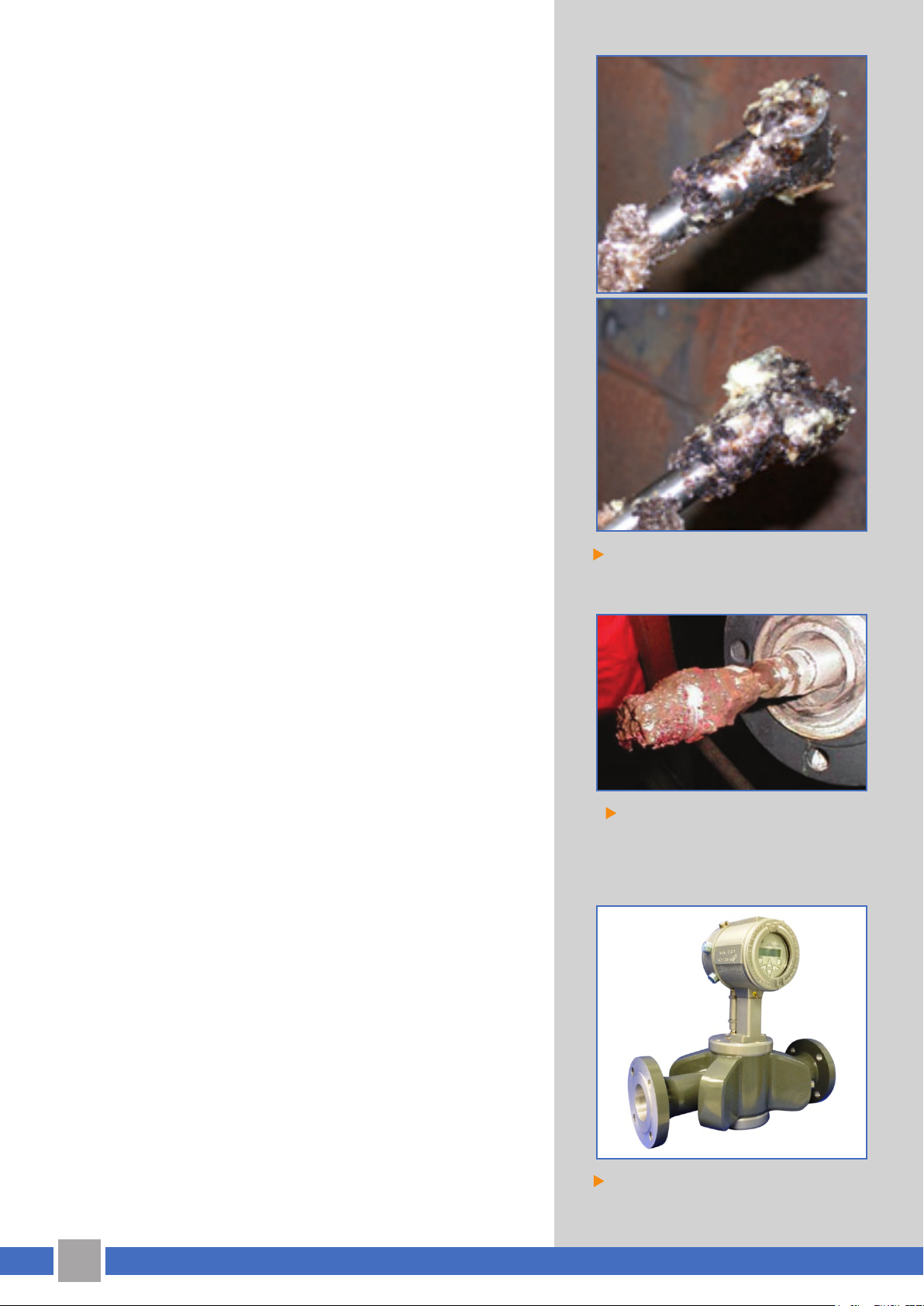
Despite this signicant amine crystal
build up, these transducers continued to
operate reliably
Glycol carry-over and dirt on this
transducer was not enough to stop GE’s
robust transducer technology in this
pipeline gas application
Maintaining a wellhead is a costly proposition. This is
especially true if the well is in a remote location, requires
special land access permitting or both. Visitation to
the wellhead should be limited to well production
2
PanaFlow Z1G Ultrasonic Flowmeter
Page 3

improvements and not be dictated by the reliability of the
ow measurement. Consider that a site-visit to a well may
cost upwards of $10,000, it is easy to understand why
product reliability is so important. Many ow measurement
technologies like orice meters, vortex meters or turbine
meters rely on, or create a pressure change to accurately
measure ow. In a clean gas this is usually acceptable,
however, in wellhead gas ow measurement the raw gas is
simply too wet and dirty, as any change in orice conditions
will directly impact ow measurement. Since Ultrasonic gas
owmeters rely on time dierential sound waves to measure
ow, raw, wet, dirty gas has little or no eect on overall meter
accuracy. While ultrasonic ow measurement technology
tends to be costlier than traditional ow measurement
technologies, advances in system design have greatly
reduced the price gap. Consider that even a single unplanned service visit to a well can cost $10,000 or more, the
added reliability of ultrasonic owmeter technology is well
worth the expense.
Coal Seam well-head with
water separator
Utlizing Advanced Technologies To
Overcome Flow Measurement Challenges
Maintaining accuracy in applications with limited
straight runs remains an industry challenge. In gas ow
measurement ideal conditions require upstream straight
runs as much as 20D. In practice, this may be dicult, costly,
or in some cases impossible to achieve. Recognizing the
challenges associated with limited straight run requirements,
especially when applied to well-head ow measurement,
GE has embarked on a comprehensive year-long study to
quantify pipe bend eects on ow proles under a wide
range of conditions. Leveraging GE’s vast experience in
aircraft engine design and by utilizing Computational Fluid
Dynamics (CFD), GE, has compiled a body of work resulting in
the ability to implement USM ow prole accuracy correction
factors for a variety of piping run conditions that compare
favorably to accuracies normally obtained in straight-runs of
20D or more.
The example to the right is the actual piping ow CFD
dynamic model of a well head skid after the water separator.
With this model GE is able to recommend the optimal meter
position on the skid to maximize accuracy and overall meter
performance as well as dene the Reynolds correction
factors to optimize meter accuracy.
Tight Gas well-head Installation
To the right, one can see the detail of how the ow prole
behaves after the separator (the “in” leg) and after the
u-bend (the “out” leg).
3
Page 4

The optimal ow meter placement would be on the out leg at 8 to 12D from the bend, as shown on the
correction factor curves to the right.
This is a great example of how GE uses CFD to enhance and optimize owmeter performance in dicult
applications. Without this enhanced CFD modeling the meter accuracy would be lost. Consider a meter
placed on the in leg. Depending on meter location, un-corrected meter on the in leg may have an
additional added inaccuracy of 2-5%.
Accuracy Through True Calibration
Wellhead meter accuracy is another key parameter in the
consideration of a ow measurement technology. Z1G
ultrasonic owmeters consistently meet 1.5% accuracy
across the documented ow velocity range, from 1.7 ft/s up
to 60 ft/s, the limit of the calibration lab. As expected, the
owmeter shows even better accuracy at higher ows; for
example, all the meters meet 0.5% accuracy at 60 ft/s and
above. All Z1G meters go through a rigorous calibration,
assuring accuracy across the entire range of ows.
Global In Scope Local In Presence
With a footprint that is global in scope but local in presence,
GE Measurement and Sensing reaches globally in technical
achievement, product performance and product quality; but
acts locally in customer focus, service and support. With
service and applications centers around the globe, staed
with skilled engineers and technicians, GE Measurement
and Sensing is well positioned to provide timely support at
remote locations at a moment’s notice. GE Measurement
and Sensing is your partner in assuring the health and
performance of your critical oil and gas assets.
Contact your Local Account Manager for more information.
Z1G Coal Seam meter calibration results
Global Service Centers
4
 Loading...