

Page 1
GE
Sensing
OxyTrak™ 390
Panametrics Flue Gas Analyzer
User’s Manual
910-264B3
September 2007
The OxyTrak™ 390 Flue Gas Analyzer is a Panametrics product. Panametrics has joined other GE hightechnology sensing businesses under a new name—GE Sensing.
Page 2

September 2007
Warranty Each instrument manufactured by GE Sensing, Inc. is warranted to be
free from defects in material and workmanship. Liability under this
warranty is limited to restoring the instrument to normal operation or
replacing the instrument, at the sole discretion of GE. Fuses and
batteries are specifically excluded from any liability. This warranty is
effective from the date of delivery to the original purchaser. If GE
determines that the equipment was defective, the warranty period is:
• one year for general electronic failures of the instrument
• one year for mechanical failures of the sensor
If GE determines that the equipment was damaged by misuse,
improper installation, the use of unauthorized replacement parts, or
operating conditions outside the guidelines specified by GE, the
repairs are not covered under this warranty.
The warranties set forth herein are exclusive and are in lieu of
all other warranties whether statutory, express or implied
(including warranties of merchantability and fitness for a
particular purpose, and warranties arising from course of
dealing or usage or trade).
Return Policy If a GE Sensing, Inc. instrument malfunctions within the warranty
period, the following procedure must be completed:
1. Notify GE, giving full details of the problem, and provide the model
number and serial number of the instrument. If the nature of the
problem indicates the need for factory service, GE will issue a
RETURN AUTHORIZATION number (RA), and shipping instructions
for the return of the instrument to a service center will be
provided.
2. If GE instructs you to send your instrument to a service center, it
must be shipped prepaid to the authorized repair station indicated
in the shipping instructions.
3. Upon receipt, GE will evaluate the instrument to determine the
cause of the malfunction.
Then, one of the following courses of action will then be taken:
• If the damage is covered under the terms of the warranty, the
instrument will be repaired at no cost to the owner and returned.
• If GE determines that the damage is not covered under the terms
of the warranty, or if the warranty has expired, an estimate for the
cost of the repairs at standard rates will be provided. Upon receipt
of the owner’s approval to proceed, the instrument will be repaired
and returned.
iii
Page 3

September 2007
Table of Contents
Chapter 1: General Information
Introduction . . . . . . . . . . . . . . . . . . . . . . . . . . . . . . . . . . . . . . . . . . . . . . . . . . . . . . . . . . . . . . . . . . . . . . . . . . . . . . . 1-1
Physical Description . . . . . . . . . . . . . . . . . . . . . . . . . . . . . . . . . . . . . . . . . . . . . . . . . . . . . . . . . . . . . . . . . . . . . . . . 1-1
Sample System. . . . . . . . . . . . . . . . . . . . . . . . . . . . . . . . . . . . . . . . . . . . . . . . . . . . . . . . . . . . . . . . . . . . . . . . . 1-3
Display Controller . . . . . . . . . . . . . . . . . . . . . . . . . . . . . . . . . . . . . . . . . . . . . . . . . . . . . . . . . . . . . . . . . . . . . . 1-7
Principles of Operation . . . . . . . . . . . . . . . . . . . . . . . . . . . . . . . . . . . . . . . . . . . . . . . . . . . . . . . . . . . . . . . . . . . . . 1-8
Zirconium Oxide Oxygen Sensor . . . . . . . . . . . . . . . . . . . . . . . . . . . . . . . . . . . . . . . . . . . . . . . . . . . . . . . . 1-9
Platinum-Catalyst Combustibles Sensor . . . . . . . . . . . . . . . . . . . . . . . . . . . . . . . . . . . . . . . . . . . . . . . . 1-10
Heater Control Circuit . . . . . . . . . . . . . . . . . . . . . . . . . . . . . . . . . . . . . . . . . . . . . . . . . . . . . . . . . . . . . . . . .1-11
Chapter 2: Installation
Introduction . . . . . . . . . . . . . . . . . . . . . . . . . . . . . . . . . . . . . . . . . . . . . . . . . . . . . . . . . . . . . . . . . . . . . . . . . . . . . . . 2-1
Unpacking . . . . . . . . . . . . . . . . . . . . . . . . . . . . . . . . . . . . . . . . . . . . . . . . . . . . . . . . . . . . . . . . . . . . . . . . . . . . . . . . . 2-1
Installation Site . . . . . . . . . . . . . . . . . . . . . . . . . . . . . . . . . . . . . . . . . . . . . . . . . . . . . . . . . . . . . . . . . . . . . . . . . . . . 2-2
Selecting the Site . . . . . . . . . . . . . . . . . . . . . . . . . . . . . . . . . . . . . . . . . . . . . . . . . . . . . . . . . . . . . . . . . . . . . . . 2-2
Preparing the Site . . . . . . . . . . . . . . . . . . . . . . . . . . . . . . . . . . . . . . . . . . . . . . . . . . . . . . . . . . . . . . . . . . . . . . 2-3
Mounting . . . . . . . . . . . . . . . . . . . . . . . . . . . . . . . . . . . . . . . . . . . . . . . . . . . . . . . . . . . . . . . . . . . . . . . . . . . . . . . . . . 2-5
Wiring . . . . . . . . . . . . . . . . . . . . . . . . . . . . . . . . . . . . . . . . . . . . . . . . . . . . . . . . . . . . . . . . . . . . . . . . . . . . . . . . . . . . . 2-6
CE Mark Compliance . . . . . . . . . . . . . . . . . . . . . . . . . . . . . . . . . . . . . . . . . . . . . . . . . . . . . . . . . . . . . . . . . . . 2-7
Wiring the Analog Outputs (A-C). . . . . . . . . . . . . . . . . . . . . . . . . . . . . . . . . . . . . . . . . . . . . . . . . . . . . . . . . 2-8
Wiring the Alarm Relays (A-D) . . . . . . . . . . . . . . . . . . . . . . . . . . . . . . . . . . . . . . . . . . . . . . . . . . . . . . . . . . . 2-8
Wiring the Calibration Relays (E-H) . . . . . . . . . . . . . . . . . . . . . . . . . . . . . . . . . . . . . . . . . . . . . . . . . . . . . . 2-9
Wiring the RS232 Output . . . . . . . . . . . . . . . . . . . . . . . . . . . . . . . . . . . . . . . . . . . . . . . . . . . . . . . . . . . . . . 2-10
Wiring the RS485 Output . . . . . . . . . . . . . . . . . . . . . . . . . . . . . . . . . . . . . . . . . . . . . . . . . . . . . . . . . . . . . . 2-10
Remote Display Option . . . . . . . . . . . . . . . . . . . . . . . . . . . . . . . . . . . . . . . . . . . . . . . . . . . . . . . . . . . . . . . . 2-11
Wiring the Line Power . . . . . . . . . . . . . . . . . . . . . . . . . . . . . . . . . . . . . . . . . . . . . . . . . . . . . . . . . . . . . . . . . 2-13
Chapter 3: Operation
Introduction . . . . . . . . . . . . . . . . . . . . . . . . . . . . . . . . . . . . . . . . . . . . . . . . . . . . . . . . . . . . . . . . . . . . . . . . . . . . . . . 3-1
Preventing Common Problems. . . . . . . . . . . . . . . . . . . . . . . . . . . . . . . . . . . . . . . . . . . . . . . . . . . . . . . . . . . . . . 3-1
Cleaning the Enclosure . . . . . . . . . . . . . . . . . . . . . . . . . . . . . . . . . . . . . . . . . . . . . . . . . . . . . . . . . . . . . . . . . . . . . 3-2
Powering Up the System . . . . . . . . . . . . . . . . . . . . . . . . . . . . . . . . . . . . . . . . . . . . . . . . . . . . . . . . . . . . . . . . . . . 3-2
The Display and Keypad . . . . . . . . . . . . . . . . . . . . . . . . . . . . . . . . . . . . . . . . . . . . . . . . . . . . . . . . . . . . . . . . 3-2
Entering Programming Mode . . . . . . . . . . . . . . . . . . . . . . . . . . . . . . . . . . . . . . . . . . . . . . . . . . . . . . . . . . . . . . . 3-3
Exiting Programming Mode . . . . . . . . . . . . . . . . . . . . . . . . . . . . . . . . . . . . . . . . . . . . . . . . . . . . . . . . . . . . . . . . . 3-4
Temporary Exit . . . . . . . . . . . . . . . . . . . . . . . . . . . . . . . . . . . . . . . . . . . . . . . . . . . . . . . . . . . . . . . . . . . . . . . . . 3-4
Locking Programming Mode . . . . . . . . . . . . . . . . . . . . . . . . . . . . . . . . . . . . . . . . . . . . . . . . . . . . . . . . . . . . 3-4
Powering Down the System. . . . . . . . . . . . . . . . . . . . . . . . . . . . . . . . . . . . . . . . . . . . . . . . . . . . . . . . . . . . . . . . . 3-5
Taking Measurements . . . . . . . . . . . . . . . . . . . . . . . . . . . . . . . . . . . . . . . . . . . . . . . . . . . . . . . . . . . . . . . . . . . . . . 3-5
v
Page 4

September 2007
Table of Contents (cont.)
Chapter 4: Setting Up the Display
Introduction . . . . . . . . . . . . . . . . . . . . . . . . . . . . . . . . . . . . . . . . . . . . . . . . . . . . . . . . . . . . . . . . . . . . . . . . . . . . . . . 4-1
Selecting the Number of Views . . . . . . . . . . . . . . . . . . . . . . . . . . . . . . . . . . . . . . . . . . . . . . . . . . . . . . . . . . . . . 4-2
Adjusting the Display Contrast . . . . . . . . . . . . . . . . . . . . . . . . . . . . . . . . . . . . . . . . . . . . . . . . . . . . . . . . . . . . . . 4-3
Selecting the Measurement Mode and Units. . . . . . . . . . . . . . . . . . . . . . . . . . . . . . . . . . . . . . . . . . . . . . . . . 4-4
Measurement Units Description . . . . . . . . . . . . . . . . . . . . . . . . . . . . . . . . . . . . . . . . . . . . . . . . . . . . . . . . . . . . 4-5
Chapter 5: General Programming
Introduction . . . . . . . . . . . . . . . . . . . . . . . . . . . . . . . . . . . . . . . . . . . . . . . . . . . . . . . . . . . . . . . . . . . . . . . . . . . . . . . 5-1
Setup Menu (Real Time Clock). . . . . . . . . . . . . . . . . . . . . . . . . . . . . . . . . . . . . . . . . . . . . . . . . . . . . . . . . . . . . . . 5-2
Calibrate Menu . . . . . . . . . . . . . . . . . . . . . . . . . . . . . . . . . . . . . . . . . . . . . . . . . . . . . . . . . . . . . . . . . . . . . . . . . . . . 5-3
Manual, One-Gas Oxygen Calibration . . . . . . . . . . . . . . . . . . . . . . . . . . . . . . . . . . . . . . . . . . . . . . . . . . . 5-3
Manual, Two-Gas Combustibles Calibration . . . . . . . . . . . . . . . . . . . . . . . . . . . . . . . . . . . . . . . . . . . . . 5-4
Automatic, One-Gas Oxygen Calibration. . . . . . . . . . . . . . . . . . . . . . . . . . . . . . . . . . . . . . . . . . . . . . . . . 5-5
Output Menu . . . . . . . . . . . . . . . . . . . . . . . . . . . . . . . . . . . . . . . . . . . . . . . . . . . . . . . . . . . . . . . . . . . . . . . . . . . . . 5-11
Measure . . . . . . . . . . . . . . . . . . . . . . . . . . . . . . . . . . . . . . . . . . . . . . . . . . . . . . . . . . . . . . . . . . . . . . . . . . . . . . 5-11
Type . . . . . . . . . . . . . . . . . . . . . . . . . . . . . . . . . . . . . . . . . . . . . . . . . . . . . . . . . . . . . . . . . . . . . . . . . . . . . . . . . . 5-12
Range . . . . . . . . . . . . . . . . . . . . . . . . . . . . . . . . . . . . . . . . . . . . . . . . . . . . . . . . . . . . . . . . . . . . . . . . . . . . . . . . 5-12
Trim . . . . . . . . . . . . . . . . . . . . . . . . . . . . . . . . . . . . . . . . . . . . . . . . . . . . . . . . . . . . . . . . . . . . . . . . . . . . . . . . . . 5-13
Cal Setting . . . . . . . . . . . . . . . . . . . . . . . . . . . . . . . . . . . . . . . . . . . . . . . . . . . . . . . . . . . . . . . . . . . . . . . . . . . . 5-15
Relays Menu . . . . . . . . . . . . . . . . . . . . . . . . . . . . . . . . . . . . . . . . . . . . . . . . . . . . . . . . . . . . . . . . . . . . . . . . . . . . . . 5-16
Relays A-D . . . . . . . . . . . . . . . . . . . . . . . . . . . . . . . . . . . . . . . . . . . . . . . . . . . . . . . . . . . . . . . . . . . . . . . . . . . . 5-16
Relays E-H . . . . . . . . . . . . . . . . . . . . . . . . . . . . . . . . . . . . . . . . . . . . . . . . . . . . . . . . . . . . . . . . . . . . . . . . . . . . 5-21
Communications Menu. . . . . . . . . . . . . . . . . . . . . . . . . . . . . . . . . . . . . . . . . . . . . . . . . . . . . . . . . . . . . . . . . . . . 5-22
RS232/RS485 Port. . . . . . . . . . . . . . . . . . . . . . . . . . . . . . . . . . . . . . . . . . . . . . . . . . . . . . . . . . . . . . . . . . . . . 5-22
Ethernet Port. . . . . . . . . . . . . . . . . . . . . . . . . . . . . . . . . . . . . . . . . . . . . . . . . . . . . . . . . . . . . . . . . . . . . . . . . . 5-24
Chapter 6: Advanced Programming
Introduction . . . . . . . . . . . . . . . . . . . . . . . . . . . . . . . . . . . . . . . . . . . . . . . . . . . . . . . . . . . . . . . . . . . . . . . . . . . . . . . 6-1
Display, Relays, and Communications Menus . . . . . . . . . . . . . . . . . . . . . . . . . . . . . . . . . . . . . . . . . . . . . . . . 6-1
Output Menu . . . . . . . . . . . . . . . . . . . . . . . . . . . . . . . . . . . . . . . . . . . . . . . . . . . . . . . . . . . . . . . . . . . . . . . . . . . . . . 6-2
Calibrate Menu . . . . . . . . . . . . . . . . . . . . . . . . . . . . . . . . . . . . . . . . . . . . . . . . . . . . . . . . . . . . . . . . . . . . . . . . . . . . 6-2
O2 Tolerance . . . . . . . . . . . . . . . . . . . . . . . . . . . . . . . . . . . . . . . . . . . . . . . . . . . . . . . . . . . . . . . . . . . . . . . . . . 6-3
Combustibles Tolerance . . . . . . . . . . . . . . . . . . . . . . . . . . . . . . . . . . . . . . . . . . . . . . . . . . . . . . . . . . . . . . . . 6-3
Setup Menu. . . . . . . . . . . . . . . . . . . . . . . . . . . . . . . . . . . . . . . . . . . . . . . . . . . . . . . . . . . . . . . . . . . . . . . . . . . . . . . . 6-4
O2 Sensor Temp . . . . . . . . . . . . . . . . . . . . . . . . . . . . . . . . . . . . . . . . . . . . . . . . . . . . . . . . . . . . . . . . . . . . . . . 6-4
Heater Block Temp . . . . . . . . . . . . . . . . . . . . . . . . . . . . . . . . . . . . . . . . . . . . . . . . . . . . . . . . . . . . . . . . . . . . . 6-5
Auto Cal Method . . . . . . . . . . . . . . . . . . . . . . . . . . . . . . . . . . . . . . . . . . . . . . . . . . . . . . . . . . . . . . . . . . . . . . . 6-6
Blow Back . . . . . . . . . . . . . . . . . . . . . . . . . . . . . . . . . . . . . . . . . . . . . . . . . . . . . . . . . . . . . . . . . . . . . . . . . . . . 6-12
Factory Menu . . . . . . . . . . . . . . . . . . . . . . . . . . . . . . . . . . . . . . . . . . . . . . . . . . . . . . . . . . . . . . . . . . . . . . . . . . . . . 6-14
Versions . . . . . . . . . . . . . . . . . . . . . . . . . . . . . . . . . . . . . . . . . . . . . . . . . . . . . . . . . . . . . . . . . . . . . . . . . . . . . . 6-14
Upgrade . . . . . . . . . . . . . . . . . . . . . . . . . . . . . . . . . . . . . . . . . . . . . . . . . . . . . . . . . . . . . . . . . . . . . . . . . . . . . . 6-14
Default Analyzer . . . . . . . . . . . . . . . . . . . . . . . . . . . . . . . . . . . . . . . . . . . . . . . . . . . . . . . . . . . . . . . . . . . . . . 6-15
Additional Menu Options . . . . . . . . . . . . . . . . . . . . . . . . . . . . . . . . . . . . . . . . . . . . . . . . . . . . . . . . . . . . . . 6-15
vi
Page 5

September 2007
Table of Contents (cont.)
Chapter 7: Specifications
Performance. . . . . . . . . . . . . . . . . . . . . . . . . . . . . . . . . . . . . . . . . . . . . . . . . . . . . . . . . . . . . . . . . . . . . . . . . . . . . . . 7-1
Functional . . . . . . . . . . . . . . . . . . . . . . . . . . . . . . . . . . . . . . . . . . . . . . . . . . . . . . . . . . . . . . . . . . . . . . . . . . . . . . . . . 7-2
Physical . . . . . . . . . . . . . . . . . . . . . . . . . . . . . . . . . . . . . . . . . . . . . . . . . . . . . . . . . . . . . . . . . . . . . . . . . . . . . . . . . . . 7-3
Calibration . . . . . . . . . . . . . . . . . . . . . . . . . . . . . . . . . . . . . . . . . . . . . . . . . . . . . . . . . . . . . . . . . . . . . . . . . . . . . . . . . 7-3
Ordering Information . . . . . . . . . . . . . . . . . . . . . . . . . . . . . . . . . . . . . . . . . . . . . . . . . . . . . . . . . . . . . . . . . . . . . . . 7-4
Appendix A: The Nernst Equation
Introduction . . . . . . . . . . . . . . . . . . . . . . . . . . . . . . . . . . . . . . . . . . . . . . . . . . . . . . . . . . . . . . . . . . . . . . . . . . . . . . . A-1
Equilibrium Conditions. . . . . . . . . . . . . . . . . . . . . . . . . . . . . . . . . . . . . . . . . . . . . . . . . . . . . . . . . . . . . . . . . . . . . . A-1
The OxyTrak™ 390 Equation . . . . . . . . . . . . . . . . . . . . . . . . . . . . . . . . . . . . . . . . . . . . . . . . . . . . . . . . . . . . . . . . A-2
Appendix B: Menu Maps
Display and Setup Menu Map (2719 passcode). . . . . . . . . . . . . . . . . . . . . . . . . . . . . . . . . . . . . . . . . . . . . . . B-1
Outputs and Relays Menu Map (2719 passcode) . . . . . . . . . . . . . . . . . . . . . . . . . . . . . . . . . . . . . . . . . . . . . B-2
Calibrate and Communications Menu Map (2719 passcode) . . . . . . . . . . . . . . . . . . . . . . . . . . . . . . . . . . B-3
Calibrate, Output and Factory Menu Map (2719 passcode) . . . . . . . . . . . . . . . . . . . . . . . . . . . . . . . . . . . B-4
Setup Menu Map (7378 passcode). . . . . . . . . . . . . . . . . . . . . . . . . . . . . . . . . . . . . . . . . . . . . . . . . . . . . . . . . . . B-5
Appendix C: Calibration, Standard Convection
Introduction . . . . . . . . . . . . . . . . . . . . . . . . . . . . . . . . . . . . . . . . . . . . . . . . . . . . . . . . . . . . . . . . . . . . . . . . . . . . . . . C-1
Method #1 . . . . . . . . . . . . . . . . . . . . . . . . . . . . . . . . . . . . . . . . . . . . . . . . . . . . . . . . . . . . . . . . . . . . . . . . . . . . . . . . . C-2
Method #2 . . . . . . . . . . . . . . . . . . . . . . . . . . . . . . . . . . . . . . . . . . . . . . . . . . . . . . . . . . . . . . . . . . . . . . . . . . . . . . . . . C-2
Method #3 . . . . . . . . . . . . . . . . . . . . . . . . . . . . . . . . . . . . . . . . . . . . . . . . . . . . . . . . . . . . . . . . . . . . . . . . . . . . . . . . . C-3
Method #4 . . . . . . . . . . . . . . . . . . . . . . . . . . . . . . . . . . . . . . . . . . . . . . . . . . . . . . . . . . . . . . . . . . . . . . . . . . . . . . . . . C-3
Method #5 . . . . . . . . . . . . . . . . . . . . . . . . . . . . . . . . . . . . . . . . . . . . . . . . . . . . . . . . . . . . . . . . . . . . . . . . . . . . . . . . . C-4
Method #6 . . . . . . . . . . . . . . . . . . . . . . . . . . . . . . . . . . . . . . . . . . . . . . . . . . . . . . . . . . . . . . . . . . . . . . . . . . . . . . . . . C-4
Method #7 . . . . . . . . . . . . . . . . . . . . . . . . . . . . . . . . . . . . . . . . . . . . . . . . . . . . . . . . . . . . . . . . . . . . . . . . . . . . . . . . . C-5
Calibration Gases . . . . . . . . . . . . . . . . . . . . . . . . . . . . . . . . . . . . . . . . . . . . . . . . . . . . . . . . . . . . . . . . . . . . . . . . . . C-5
Appendix D: Calibration, Aspirated Flow
Response Test . . . . . . . . . . . . . . . . . . . . . . . . . . . . . . . . . . . . . . . . . . . . . . . . . . . . . . . . . . . . . . . . . . . . . . . . . . . . .D-1
Calibration Gas Flow Rate Test. . . . . . . . . . . . . . . . . . . . . . . . . . . . . . . . . . . . . . . . . . . . . . . . . . . . . . . . . . . . . . D-1
Oxygen Sensor Field Calibration . . . . . . . . . . . . . . . . . . . . . . . . . . . . . . . . . . . . . . . . . . . . . . . . . . . . . . . . . . . . D-2
Manual Calibration . . . . . . . . . . . . . . . . . . . . . . . . . . . . . . . . . . . . . . . . . . . . . . . . . . . . . . . . . . . . . . . . . . . . . D-2
vii
Page 6

September 2007
Table of Contents (cont.)
Appendix E: Default Settings
Calibration Sheet Example . . . . . . . . . . . . . . . . . . . . . . . . . . . . . . . . . . . . . . . . . . . . . . . . . . . . . . . . . . . . . . . . . E-1
Display Defaults . . . . . . . . . . . . . . . . . . . . . . . . . . . . . . . . . . . . . . . . . . . . . . . . . . . . . . . . . . . . . . . . . . . . . . . . . . . E-2
Calibrate Defaults. . . . . . . . . . . . . . . . . . . . . . . . . . . . . . . . . . . . . . . . . . . . . . . . . . . . . . . . . . . . . . . . . . . . . . . . . . E-3
Output Defaults . . . . . . . . . . . . . . . . . . . . . . . . . . . . . . . . . . . . . . . . . . . . . . . . . . . . . . . . . . . . . . . . . . . . . . . . . . . . E-4
Output A. . . . . . . . . . . . . . . . . . . . . . . . . . . . . . . . . . . . . . . . . . . . . . . . . . . . . . . . . . . . . . . . . . . . . . . . . . . . . . . E-4
Output B. . . . . . . . . . . . . . . . . . . . . . . . . . . . . . . . . . . . . . . . . . . . . . . . . . . . . . . . . . . . . . . . . . . . . . . . . . . . . . . E-5
Output C. . . . . . . . . . . . . . . . . . . . . . . . . . . . . . . . . . . . . . . . . . . . . . . . . . . . . . . . . . . . . . . . . . . . . . . . . . . . . . . E-6
Relays Defaults . . . . . . . . . . . . . . . . . . . . . . . . . . . . . . . . . . . . . . . . . . . . . . . . . . . . . . . . . . . . . . . . . . . . . . . . . . . . E-7
Communications Defaults . . . . . . . . . . . . . . . . . . . . . . . . . . . . . . . . . . . . . . . . . . . . . . . . . . . . . . . . . . . . . . . . . E-13
Setup Defaults . . . . . . . . . . . . . . . . . . . . . . . . . . . . . . . . . . . . . . . . . . . . . . . . . . . . . . . . . . . . . . . . . . . . . . . . . . . . E-14
Factory Defaults . . . . . . . . . . . . . . . . . . . . . . . . . . . . . . . . . . . . . . . . . . . . . . . . . . . . . . . . . . . . . . . . . . . . . . . . . . E-15
Appendix F: Blow Back Sample System
Installation . . . . . . . . . . . . . . . . . . . . . . . . . . . . . . . . . . . . . . . . . . . . . . . . . . . . . . . . . . . . . . . . . . . . . . . . . . . . . . . . F-1
Settings . . . . . . . . . . . . . . . . . . . . . . . . . . . . . . . . . . . . . . . . . . . . . . . . . . . . . . . . . . . . . . . . . . . . . . . . . . . . . . . . . . . F-1
viii
Page 7

Chapter 1
Page 8

General Information
Introduction. . . . . . . . . . . . . . . . . . . . . . . . . . . . . . . . . . . . . . . . . . . . . . . . . . . . 1-1
Physical Description . . . . . . . . . . . . . . . . . . . . . . . . . . . . . . . . . . . . . . . . . . . . 1-1
Principles of Operation . . . . . . . . . . . . . . . . . . . . . . . . . . . . . . . . . . . . . . . . . . 1-8
Page 9

September 2007
Introduction Process plant managers are usually looking for ways to reduce
expense and increase profitability . When combustibles are burned as
part of the operation, and that combustion is incomplete (allowing
unburned fuel to escape), costs go up and profits go down.
A reliable system for analyzing flue gas can provide the necessary
information to:
• adjust the flow of oxygen
• increase the efficiency of the combustion
• gain significant cost savings for the overall operation
To meet these specific needs, GE Sensing provides the OxyTrak™
390 Flue Gas Analyzer which monitors the efficiency of a furnace or
boiler by measuring excess oxygen and/or ppm
combustibles in the flue gases.
To measure these two parameters, the OxyTrak™ 390 uses:
unburned
v
• a zirconium oxide oxygen sensor
• a platinum-catalyst combustibles sensor (optional)
The oxygen sensor measures excess oxygen or, in a fuel rich
environment, equivalent combustibles. The combustibles sensor
monitors partially combusted fuel, only in the presence of excess
oxygen (i.e. there must be enough oxygen present to burn the fuel).
Each OxyTrak™ 390 may be equipped with an oxygen sensor, a
combustibles sensor, or both.
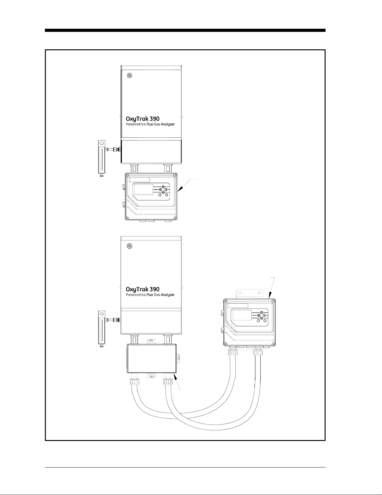
Physical Description The standard GE Sensing OxyTrak™ 390 Flue Gas Analyzer is
provided in a general-purpose weatherproof (IP52, NEMA 2)
enclosure. The analyzer consists of a convection loop/analyzer
package and a display controller, which may be mounted either
locally or remotely . Figure 1-1 on page 1-2 shows the OxyTrak™ 390
with local and remote display controllers.
General Information 1-1
Page 10
September 2007
Local Controller
ESC ENT
Remote Controller
Junction
Box
Figure 1-1: Standard OxyTrak™ 390 Configurations
ESC ENT
1-2 General Information
Page 11

September 2007
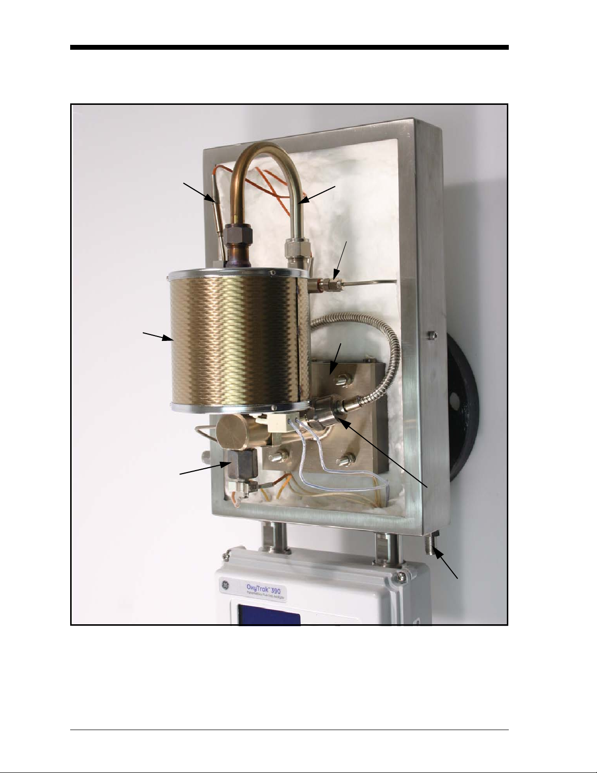
Sample System The convection loop/analyzer package houses the sample system,
which consists of the components shown in Figure 1-2 on page 1-4
and Figure 1-3 on page 1-5. The functions of the sample system
components are as follows:
• a manifold with removable thermocouple and cartridge heaters to
prevent acid components of the flue gas from condensing in the
sample system and causing corrosion
• a zirconium oxide oxygen sensor
• an optional platinum-catalyst combustibles sensor to monitor
incomplete combustion of the fuel by burning it in the presence of
excess oxygen
• a temperature-controlled sensor furnace to maintain the oxygen
sensor at a stable operating temperature and to act as the engine for
convective sampling
• a convection loop to circulate the sample gases through the sample
system
• an aspirator port to connect to an aspirated probe.
General Information 1-3
Page 12
September 2007
Sample System (cont.)
Furnace T/C
Sensor
Furnace
Convection
Loop
Aspirator
Port
Manifold
Oxygen Sensor
Combustibles
Sensor
Aspirated
Probe
Connection
Figure 1-2: The Sample System
1-4 General Information
Page 13
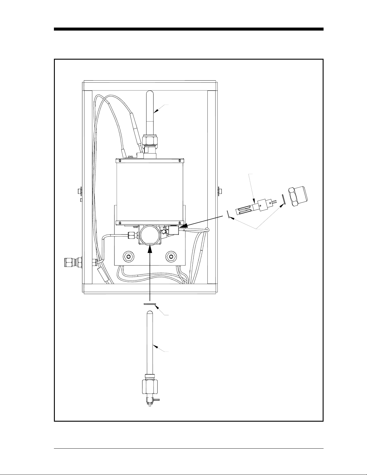
Sample System (cont.)
Sensor
Furnace
September 2007
Convection
Loop
Combustibles
Sensor
Oxygen Sensor
Washer
Zirconium Oxide
Oxygen Sensor
Combustibles
Sensor
Washers
Figure 1-3: Sensor Locations (ref. dwg #705-1088, sht 3)
General Information 1-5
Page 14
September 2007
Sample System (cont.)
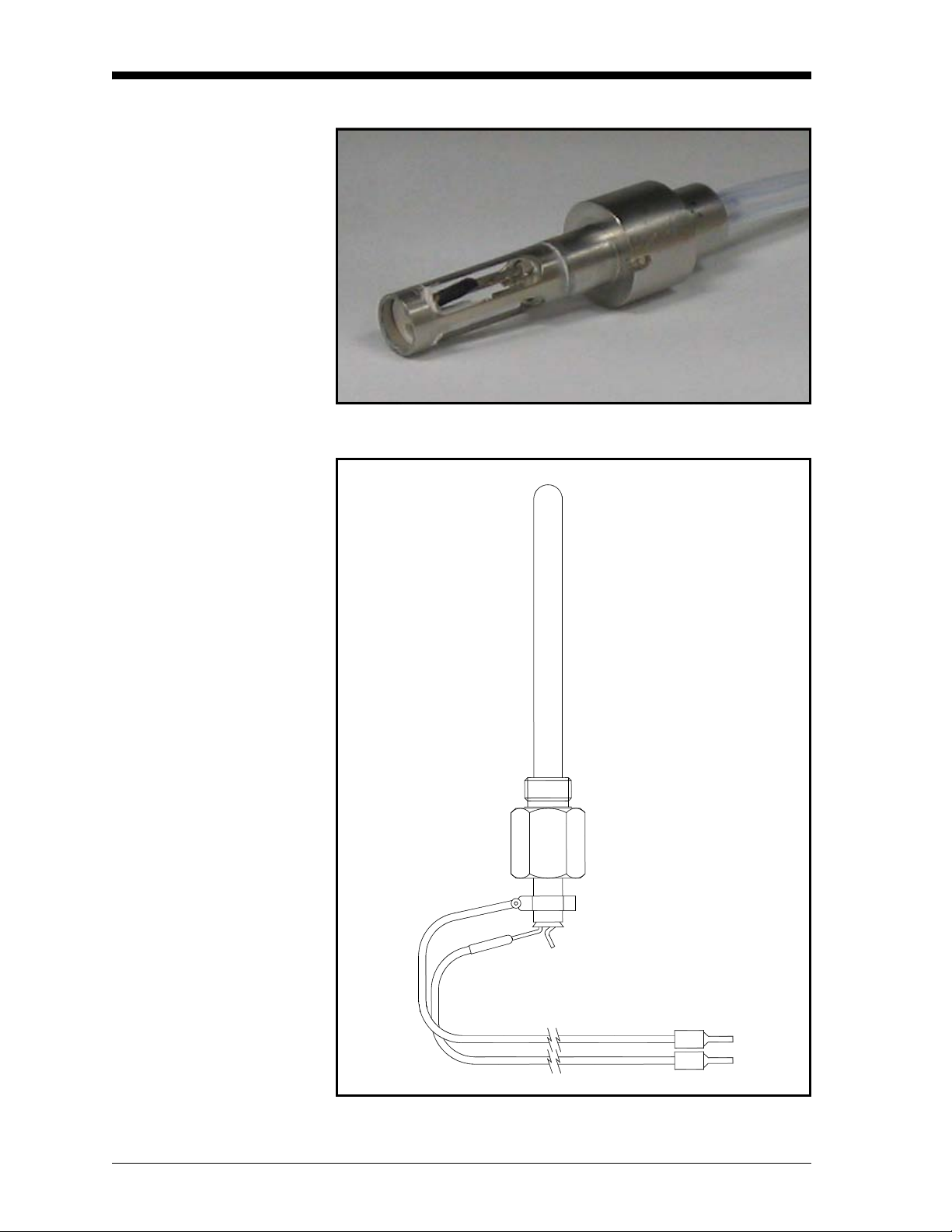
Figure 1-4: Combustibles Sensor
SENSOR POSITIVE
Figure 1-5: Zirconium Oxide Oxygen Sensor
1-6 General Information
Page 15
September 2007
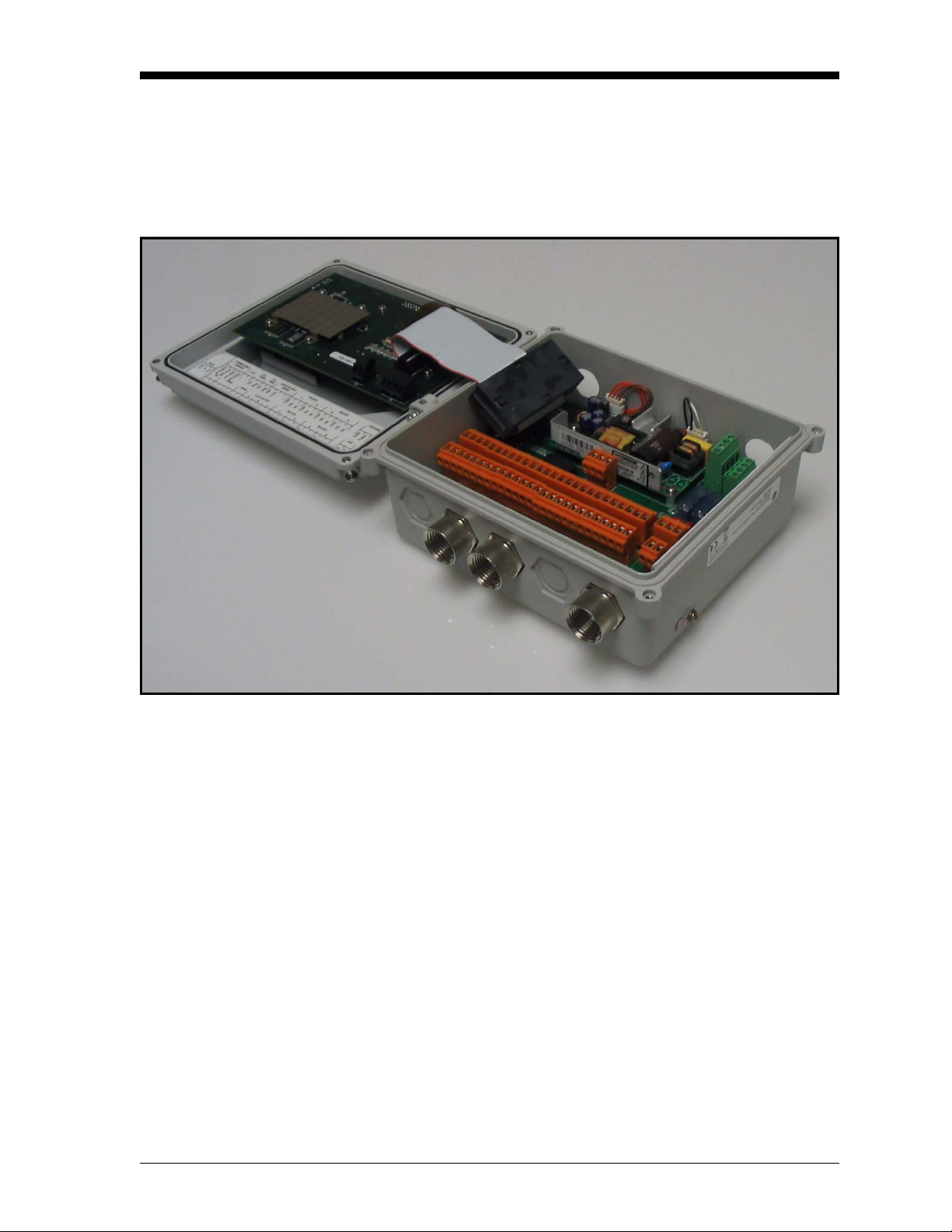
Display Controller The display controller (see Figure 1-6 below) includes the terminal
blocks for making all electrical connections and the furnace
temperature control (FTC) circuit board. The FTC board maintains a
constant sensor furnace temperature to improve the accuracy of the
oxygen analysis and to extend the life of the oxygen sensor.
Figure 1-6: Display Controller Interior
The display controller performs the following functions:
• amplifies the oxygen and combustibles sensor outputs
• linearizes the oxygen signal
• controls the sensor temperature
• outputs the reading on a 64 x 128 pixel graphic display
• enables programming using an integral keypad
• provides a linear 4-20 mA analog output
• provides four alarm relays
• provides four auto-calibration relays
• provides RS232/RS485 communications outputs
General Information 1-7
Page 16

September 2007
Principles of Operation Ideally, every furnace/burner should mix a precise ratio of air to fuel,
and the mixture should burn efficiently to yield only heat, water vapor
and carbon dioxide. However, because of burner aging, imperfect air
to fuel mixtures and changing firing rates, this rarely happens.
Monitoring the actual efficiency of the combustion process is easily
accomplished with the OxyTrak™ 390.
A flue gas sample is drawn into the probe by gaseous diffusion and a
gentle convective flow. The sample passes through the probe and into
the sample system, where it is maintained at a temperature above
200°C (392°F) by the heater block. In the presence of oxygen, this
sample temperature is high enough to burn any partial combustion
products that reach the active (platinum-coated) element of the
combustibles sensor. The resulting temperature differential between
the two combustibles sensor elements is related to the concentration
of partial combustion products in the test sample.
Note: The sampled gas is maintained above 200°C (392°F) to
prevent flue gas acids from condensing in the analyzer and
causing corrosion.
The sample then passes into the sensor furnace, which heats the
sample gas and the oxygen sensor to 700°C (1,292°F) (a temperature
above 650°C (1,202°F) is required for proper operation of the oxygen
sensor). The oxygen sensor is covered with a platinum catalyst that
causes the burning of all remaining combustibles, enabling the sensor
to measure the excess oxygen (or fuel) in the flue gas.
The sensor furnace also generates the convective flow that circulates
the sample gas through the sample system. The hot sample gas in the
sensor furnace rises out of the furnace and cools, as it is pushed from
behind by the hot gases still in the furnace. The cooled sample gases
then drop down the other branch of the convection loop and into the
annular space between the probe and probe sleeve, where they are
carried away by the gas flow in the flue.
1-8 General Information
Page 17
September 2007
Zirconium Oxide Oxygen Sensor
The inside and outside of the zirconium oxide oxygen sensor are
coated with porous platinum, forming two electrodes. The sample gas
flows past the outside of the sensor, while atmospheric air circulates
freely inside the sensor. This atmospheric air is used as the reference
gas for making oxygen measurements. See Figure 1-7 below.
Oxygen ions migrate through the zirconium oxide
along the concentration gradient.
O
O
2
O
2
O
O
2
Atmospheric O
Inside Cell
20.9%
2
Sample O
2
Outside Cell
2
O
2
2
Zirconium Oxide Ceramic
with Lattice Imperfec tio n s
From O u ts ide
Electrode
When O concentration in sample gas falls, the cell voltage rises
2
Volts
From Ins id e
Electrode
with increased oxygen migration through the zirconium oxide.
Figure 1-7: Oxygen Migration in the Zirconium Oxide Sensor
At the operating temperature of the oxygen sensor, the atmospheric
reference oxygen is electrochemically reduced at the inner electrode,
and the resulting oxygen ions seek to equalize with the lower oxygen
concentration on the sample side of the cell by migrating through the
porous ceramic toward the outer electrode. At the outer electrode they
give up electrons to become oxygen molecules again, and are swept
away by the sample gas flow.
The lower the concentration of oxygen in the flue gas sample, the
greater the rate of ion migration through the ceramic, and the higher
the cell voltage due to electron exchange at the electrodes. The cell
voltage rises logarithmically as the amount of oxygen in the flue gas
falls, allowing the accurate measurement of very low levels of excess
oxygen in the flue gas.
General Information 1-9
Page 18
September 2007
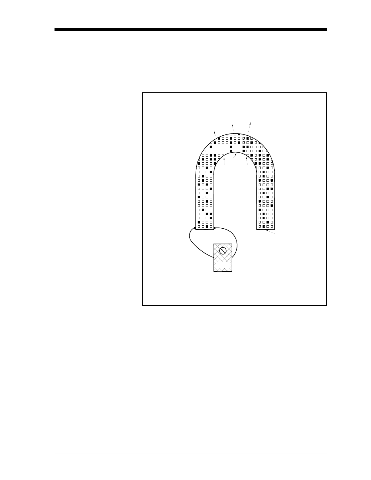
Platinum-Catalyst Combustibles Sensor
The combustibles sensor consists of two platinum thermistors
mounted side by side in the sample stream. One thermistor, the active
element, is used to detect/react partial combustion products, while the
other thermistor, the reference element, provides a baseline. The
active element is coated with a black platinum catalyst and the
reference element has a white inert surface. As the sample gas passes
over the active element, the platinum catalyst causes any
combustibles to burn (in the presence of excess oxygen), thereby
raising the temperature of the active element above that of the
reference element (see Figure 1-8 below).
Flue Gas Flow
Reference
Element
(Inert Coating)
Active
Element
(Platinum C ata ly st)
Combustibles Sensor
Figure 1-8: Combustibles Sensor Elements
The resulting temperature differential between the active and
reference elements is proportional to the concentration of
combustibles in the sample, and a corresponding resistance change is
then converted into a reading of parts per million by volume (ppm
of combustibles.
)
V
1-10 General Information
Page 19

September 2007
Heater Control Circuit The oxygen sensor temperature in the OxyTrak™ 390 is maintained
by a heater, which is part of a complex temperature control loop. This
circuit constantly monitors the oxygen sensor temperature, compares
it to the set point temperature (700°C), and turns the heater ON or
OFF accordingly. The specific type of control circuit used is called a
Proportional Integral Derivative (PID) loop, because of the three
adjustable parameters involved:
• Proportional Band: Because the system cannot respond
instantaneously to temperature changes, the actual temperature of
the oxygen sensor oscillates about the set point. In general,
increasing the proportional band reduces the magnitude of these
temperature oscillations.
• Integral Action: A consequence of increasing the proportional
band is the introduction of an offset between the set point and the
control point. The integral portion of the control loop acts to move
the control point back toward the set point within a specified
period of time. Thus, decreasing this integration time reduces the
offset more quickly.
• Derivative Action: The derivative portion of the control loop
applies a corrective signal based on the rate at which the actual
temperature is approaching the set point. In effect, the derivative
action reduces overshoot by counteracting the control signal
produced by the proportional and integral parameters.
The heater control circuit is configured at the factory for optimum
performance. Because of the strong interaction between the three
parameters involved, properly setting up the PID loop is a very
complex matter. As a result, randomly changing the P, I and/or D
parameters can seriously degrade the performance of the OxyTrak™
390.
IMPORTANT: Always contact the factory before attempting to
change the default P, I and/or D values.
General Information 1-11
Page 20

Chapter 2
Page 21

Installation
Introduction. . . . . . . . . . . . . . . . . . . . . . . . . . . . . . . . . . . . . . . . . . . . . . . . . . . . 2-1
Unpacking . . . . . . . . . . . . . . . . . . . . . . . . . . . . . . . . . . . . . . . . . . . . . . . . . . . . . 2-1
Installation Site. . . . . . . . . . . . . . . . . . . . . . . . . . . . . . . . . . . . . . . . . . . . . . . . . 2-2
Mounting . . . . . . . . . . . . . . . . . . . . . . . . . . . . . . . . . . . . . . . . . . . . . . . . . . . . . . 2-5
Wiring . . . . . . . . . . . . . . . . . . . . . . . . . . . . . . . . . . . . . . . . . . . . . . . . . . . . . . . . . 2-6
Page 22

September 2007
Introduction This chapter provides instructions on how to properly install and wire
the OxyTrak™ 390. Be sure to observe all installation limits and
precautions described in this chapter. Pay particular attention to the
specified ambient temperature range of –30 to +70°C (-22 to +158°F)
for the analyzer and –30 to +60°C (-22 to +140°F) for the controller.
!WARNING!
To ensure safe operation, the OxyTrak™ 390 must be
installed and operated as described in this manual. Also, be
sure to follow all applicable local safety codes and
regulations for installing electrical equipment. All
procedures should be performed by trained service
personnel only.
Unpacking Remove the analyzer (see Figure 2-1 below) from its shipping
container, and make sure that all items on the packing slip have been
received. If anything is missing, contact the factory immediately.
Note: See Figure 2-6 on page 2-17 (local controller) or Figure 2-7
on page 2-18 (remote controller) for a complete outline and
installation drawing of the OxyTrak™ 390.
Figure 2-1: Typical OxyTrak™ 390 with Local Controller
Installation 2-1
Page 23
September 2007
Installation Site Environmental and installation factors should already have been
discussed with a GE Sensing applications engineer or field sales
person before the OxyTrak™ 390 arrives.
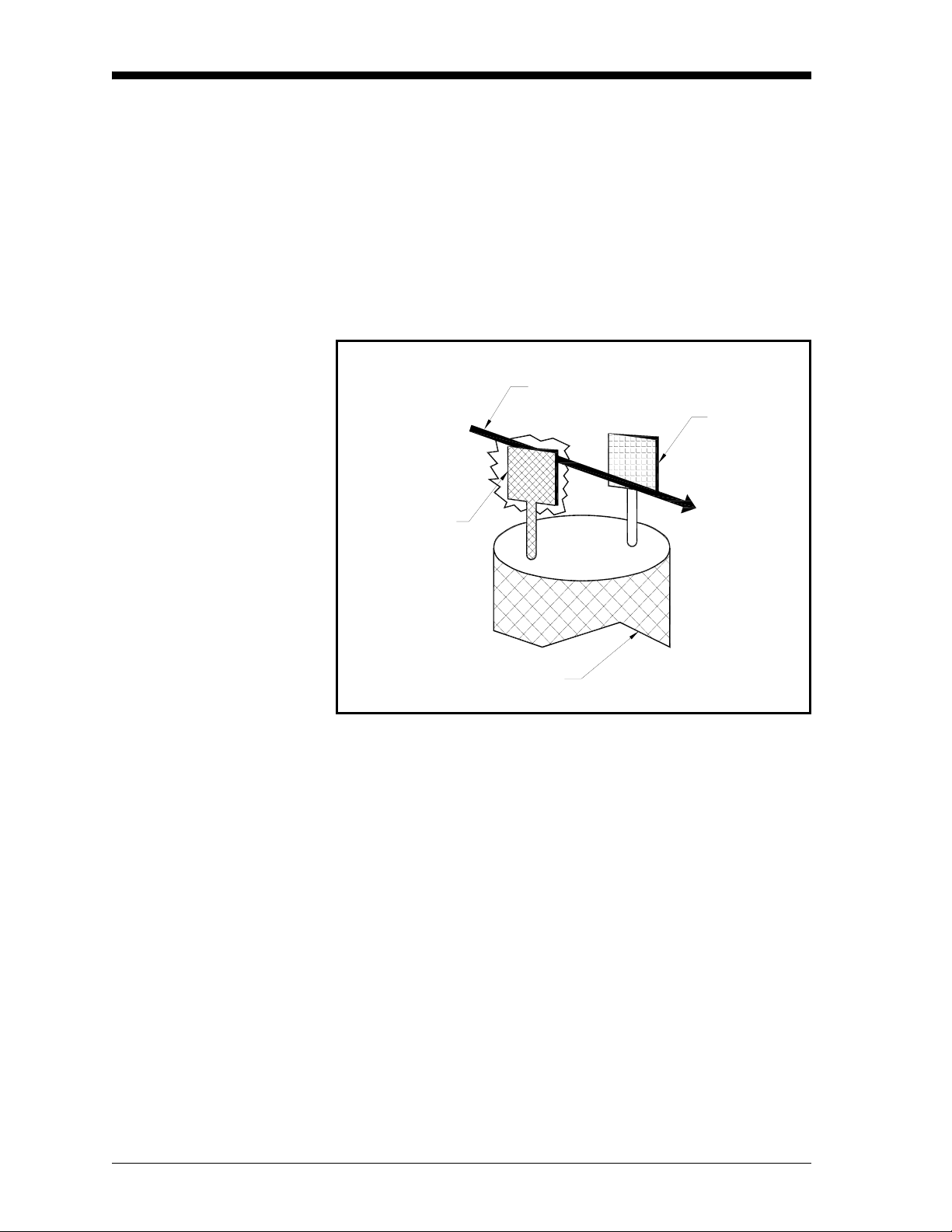
Selecting the Site The tip of the probe is typically inserted into the stack to a distance of
1/3 of the stack diameter. Also, the flue gas flow direction should be
either perpendicular to the probe or angled away from the open end of
the probe (see Figure 2-2 below).
IMPORTANT: Never allow the flue gas flow to be angled directly into
the end of the probe.
• For furnaces, locate the analyzer close to the combustion zone,
typically within the radiant section and always before the
convection section. Make sure that the probe’s maximum operating
temperature is not exceeded and that the probe is not situated in a
non-homogeneous flue gas mixture.
• For boilers, locate the analyzer downstream of the heat exchanger
and just before the economizer air heater, if one is installed. The
analyzer should not be placed downstream of any air heater,
because of possible air leaks that can cause inaccurate readings.
In general, the sample point should be an area of high turbulence,
which will ensure a good homogeneous mixture of the flue gases.
Conditions to be avoided would include air leaks upstream of the
sample point and dead spaces in the vicinity of the sample point.
Mounting Flange
Shroud
90°
90°
Probe
Probe Sleeve
Figure 2-2: Permitted Flue Gas Flow Angles
2-2 Installation
Page 24
September 2007
Selecting the Site (cont.) Finally, the following installation requirements should be observed:
• Install the OxyTrak™ 390 in a location that provides ready access
for programming, testing, and servicing the unit.
• Protect all cables from excessive physical strain (bending, pulling,
twisting, etc.).
• Be sure that the input voltage at the planned installation site is
within the limits specified for the OxyTrak™ 390.
Preparing the Site Preparation of the installation site should include the following steps
(see Figure 2-8 on page 2-19 and Figure 2-3 below):
Note: Although a horizontal installation is shown in this manual,
other mounting angles are permissible.
FRONT VIEW
GAS FLOW
SIDE VIEW
3" min
Welds
2" Sch 80 Pipe
.
Mounting Plate
1 7/8"
min.
90°
Masonry
Wall
Mating Flange
Figure 2-3: A Typical Installation Setup
Installation 2-3
Page 25

September 2007
Preparing the Site (cont.) 1. At the chosen analyzer location on the furnace or boiler wall or on
the side of a horizontal or vertical flue duct, drill a hole of the
proper diameter to accommodate a short length of pipe having at
least a 1 7/8 in. 48 mm) inside diameter. A length of 2” Schedule
80 pipe is suitable for this purpose.
2. Weld the short pipe into a mounting plate, with welds on both
sides of the plate. The pipe length must be sufficient to meet the
following requirements:
• One end of the pipe should extend through the rear of the
mounting plate sufficiently to enter the wall. For installation in
a masonry wall, the pipe should extend entirely through the
wall to prevent the probe from becoming trapped, if the wall
should crumble.
• To provide clearance for installing the flange bolts, the pipe
must be long enough to provide 4 in. (100 mm) of clearance
between the front surface of the mounting plate and the back
surface of the mating flange.
3. Weld the mating flange onto the end of the short pipe so that the
raised face of the flange faces away from the mounting plate. Be
sure that the following requirements are met:
• One end of the short pipe should be flush with the raised face of
the flange.
• The mating flange should be oriented so that its bolt holes
straddle the vertical and horizontal center lines of the mounting
plate.
Note: The OxyTrak™ 390 can be supplied with an optional flange. If
a flange is desired, it must be specified (e.g. 3”-150# flange)
at the time of purchase
4. Attach the mounting plate to the wall with the pipe extending into
the drilled hole.
For probe lengths greater than 2 meters (6 feet), a support sleeve is
recommended. Refer to Figure E-3 on page E-3.
2-4 Installation
Page 26

September 2007
Mounting This section explains how to mount OxyTrak™ 390 analyzer at the
site that was prepared in the previous section. The OxyTrak™ 390 has
integral male 1-1/2” NPT mounting threads. This permits a flange to
be threaded onto the analyzer, and the resulting assembly is then
bolted to the mating flange on the furnace/boiler wall or flue duct.
Caution!
Flue gas condensate is extremely corrosive. The OxyTrak™
390 must be wired and powered up immediately after
mounting to prevent damage to the unit. If a blowback
(purge) system is to be used, install this system and turn it on
right away also.
IMPORTANT: Direct mounting of the OxyTrak™ 390 into a threaded
hole using its mounting thr e ads is not
Always use a mounting flange.
Note: Rather than the use of a thread sealant, a high temperature
lubricant such as Molykote 1000 is recommended.
recommended.
Refer to Figure 2-8 on page 2-19, and complete the following steps to
mount the OxyTrak™ 390 convection loop/analyzer package:
1. Slide a suitable flange gasket over the probe and up against the
mounting flange on the analyzer.
Note: Be sure to use a suitable high temperature gasket for this
application.
2. Orient the analyzer so that the convection loop/ana lyzer package
is vertical, and slide the probe through the hole in the mounting
wall until the two flanges meet.
3. Using suitable hardware, make sure the gasket is properly
positioned between them, and bolt the two flanges together.
4. Continue as follows:
a. If you have a local display controller, the physical installation
is complete. Proceed to the wiring section on the next page.
b. If you have a remo te display controller, proceed to Step 5.
5. Refer to Figure 2-7 on page 2-18 and mount the remote display
controller in a convenient location. Be sure to allow sufficient
clearance for programming and operation of the unit.
6. Install suitable cable glands and conduit for the environment, to
connect the junction box on the bottom of the convection loop/
analyzer package to the display controller (2 places).
Installation 2-5
Page 27

September 2007
Wiring !Attention European Customers!
To meet CE Mark requirements, install all cables as
described on the next page.
IMPORTANT: For compliance with the European Union’s Low
Voltage Directive (73/23/EEC), the OxyTrak™ 390
requir es an external power disconnect device such as a
switch or circuit breaker. The disconnect device must
be marked as such, clearly visible, directly accessible,
and located within 1.8 m (6 ft) of the unit.
!WARNING!
To ensure safe operation, the OxyTrak™ 390 must be
installed and operated as described in this manual. Be sure
to follow all applicable local safety codes and regulations
for installing electrical equipment. All procedures should
be performed by trained service personnel only.
To wire the OxyTrak™ 390, see Figure 2-9 on page 2-20 for a local
assembly or Figure 2-10 on page 2-21 for a remote assembly, and
connect the following items to the display controller (do not
line power through the same conduit as the other connections):
run the
• alarm relays A-D
• calibration relays E-H
• 4-20 mA analog output
• RS232 or RS485 output
• line power (connect through the right-hand port)
If you have a remote display controller, you must also make the
following connections between the controller and the junction box:
• oxygen and combustibles sensors
• furnace and manifold thermocouples
• thermocouple cold junction compensation
• furnace and manifold heaters
IMPORTANT: Do not alter any of the factory-installed wiring.
To access the terminal blocks for wiring, unthread the four screws on
the front of the display controller and swing the cover open. If you
have a system with a remote display controller, you must also
unthread the three screws on the junction box and swing the cover
open.
2-6 Installation
Page 28

September 2007
CE Mark Compliance For CE Mark compliance, the OxyTrak™ 390 must meet both the
EMC and LVD directives.
IMPORTANT: CE Mark compliance is required for all units used in
EEC countries.
EMC Compliance For EMC compliance, the electrical connections must be shielded and
grounded as shown in Table 2-1 below. After all the necessary
electrical connections have been made, seal any unused cable entry
holes with standard conduit plugs or equivalent.
Note: If the instructions in this section are followed, the unit will
comply with the EMC Directive 89/336/EEC.
Table 2-1: Wiring Modifications for EMC Compliance
Connection Wiring Modification
Power 1. When connecting the power, select the cable
entry closest to the chassis ground.
2. Use shielded cable* to connect the power to the
OxyTrak™ 390 enclosure. Connect the shield to
the nearest chassis ground terminal.
3. Connect the power line ground wire to the
nearest chassis ground terminal.
Input/Output 1. Use shielded cable* to interconnect the
OxyTrak™ 390 enclosure with any external I/O
devices.
2. Connect the shields to the nearest chassis
ground terminal.
*Wires enclosed in a properly-grounded metal conduit do not
require additional shielding.
LVD Compl iance For compliance with the European Union’ s Low Voltag e Directive
(73/23/EEC), the analyzer requires an external power disconnect
device such as a switch or circuit breaker. The disconnect device must
be marked as such, clearly visible, directly accessible, and located
within 1.8 m (6 ft) of the unit.
Note: If the instructions in this section are followed, the unit will
comply with the Low Voltage Directive (73/23/EEC).
Installation 2-7
Page 29

September 2007
Wiring the Analog Outputs (A-C)
Wiring the Alarm Relays (A-D)
To wire an analog output device to the OxyTrak™ 390, refer to
Figure 2-4 on page 2-12 and Figure 2-9 on page 2-20 or Figure 2-10
on page 2-21, and make the following connections to terminal block
J11 in the display controller:
1. Connect the positive pin to the input of the analog output device:
a. Output A - J11–5 (+)
b. Output B - J11–3 (+)
c. Output C - J11–1 (+)
2. Connect the negative pin to the return of the analog output
device:
a. Output A - J11–6 (–)
b. Output B - J11–4 (–)
c. Output C - J11–2 (–)
To wire a warning device to any of the OxyTrak™ 390 ala rm relay s
(A-D), refer to Figure 2-4 on page 2-12 and Figure 2-9 on page 2-20
or Figure 2-10 on page 2-21, and make the following connections to
terminal blocks J7 and J8 in the display controller:
1. Connect the NC pin to the alarm device input for failsafe
operation, or leave this pin unused for non-failsafe operation:
a. Relay A - J7–4 (NC)
b. Relay B - J7–1 (NC)
c. Relay C - J8–4 (NC)
d. Relay D - J8–1 (NC)
2. Connect COM pin to the alarm device return:
a. Relay A - J7–6 (COM)
b. Relay B - J7–3 (COM)
c. Relay C - J8–6 (COM)
d. Relay D - J8–3 (COM)
3. Connect the NO pin to the alarm device input for non-failsafe
operation, or leave this pin unused for failsafe operation:
a. Relay A - J7–5 (NO)
b. Relay B - J7–2 (NO)
c. Relay C - J8–5 (NO)
d. Relay D - J8–2 (NO)
2-8 Installation
Page 30

September 2007
Wiring the Calibration Relays (E-H)
To wire a warning device to any of the OxyTrak™ 390 calibrati on
relays (E-H), refer to Figure 2-4 on page 2-12 and Figure 2-9 on p age
2-20 or Figure 2-10 on page 2-21, and make the following
connections to terminal blocks J9 and J10 in the display controller:
1. Connect the NC pin to the alarm device input for failsafe
operation, or leave this pin unused for non-failsafe operation:
a. Relay E - J9–3 (NC)
b. Relay F - J9–6 (NC)
c. Relay G - J10–3 (NC)
d. Relay H - J10–6 (NC)
2. Connect the COM pin to the alarm device return:
a. Relay E - J9–1 (COM)
b. Relay F - J9–4 (COM)
c. Relay G - J10–1 (COM)
d. Relay H - J10–4 (COM)
3. Connect the NO pin to the alarm device input for non-failsafe
operation, or leave this pin unused for failsafe operation:
a. Relay E - J9–2 (NO)
b. Relay F - J9–5 (NO)
c. Relay G - J10–2 (NO)
d. Relay H - J10–5 (NO)
Note: The OxyTrak™ 390 relays do not provide power. To use the
Blow Back process, connect a power supply in series with
Relay H and the Blow Back solenoid valve.
Installation 2-9
Page 31

September 2007
Wiring the RS232 Output To wire the OxyTrak™ 390 to the RS232 serial port on a PC, refer to
Figure 2-4 on page 2-12 and Figure 2-9 on page 2-20 or Figure 2-10
on page 2-21, and make the following connections to J14 in the
display controller:
IMPORTANT: You may make either an RS232 connection or an
RS485 connection, but not both at the same time.
Note: This connection may be made with a GE Sensing #704-668-xx
cable. If this cable is used, pin #1 is the white wire, pin #2 is
the red wire, and pin #3 is the green wire.
1. Connect J14–1 (OUT) to the transmit pin on the computer.
2. Connect J14–2 (IN) to the receive pin on the computer.
3. Connect J14–3 (EN) to the return pin on the computer.
Note: See GE Sensing document EIA-RS Serial Communications
(916-054) for a detailed discussion of serial port connections.
Wiring the RS485 Output To wire the OxyTrak™ 390 to a remote RS485 controller, refer to
Figure 2-4 on page 2-12 and Figure 2-9 on page 2-20 or Figure 2-10
on page 2-21, and make the following connections to terminal block
J13 in the display controller:
IMPORTANT: One may make either an RS232 connection or an
RS485 connection, but not both at the same time.
1. Connect J13–1 to Return on the RS485 system.
2. Connect J13–2 to 12V on the RS485 system.
3. Connect J13–3 to (+) on the RS485 system.
4. Connect J13–4 to (–) on the RS485 system.
2-10 Installation
Page 32

September 2007
Remote Display Option If you have a local display controller, skip this section and proceed to
the next page to wire your line power. Otherwise, wire the remote
display controller to the junction box on the convection loop/analyzer
package as follows (see Figure 2-4 on page 2-12 and Figure 2-10 on
page 2-21):
Wiring the Signal Cable
Assembly (704-1104)
1. Wire the combustibles sensor:
a. Using the RED wire from the red/black pair, connect junction
box terminal J3–1 (CO ACT / BLK) to display controller
terminal J4–1 (ACT / BLK).
b. Using the BLACK wire from the red/black pair, connect
junction box terminal J3–2 (CO REF / GRN) to display
controller terminal J4–2 (REF / GRN).
c. Using the GREEN wire from the green/black pair, connect
junction box J3–3 (CO ACT / RED) to display controller
terminal J4–3 (ACT / RED).
d. Using the BLACK wire from the green/ black pair, connect
junction box terminal J3–4 (CO REF / YEL) to display controller
terminal J4–4 (REF / YEL).
2. Wire the oxygen sensor:
a. Using the WHITE wire from the white/black pair, connect
junction box terminal J2–1 (O2+) to display controller terminal
J1–1 (O2+).
b. Using the BLACK wire from the white/black pair, connect
junction box terminal J2–2 (O2-) to display controller terminal
J1–2 (O2-).
3. Wire the furnace thermocouple:
a. Using the BLUE wire from the blue/black pair, connect junction
box terminal J1–3 (T/C FURN +) to display controller terminal
J6–3 (T/C FURN +).
b. Using the BLACK wire from the blue/black pair, connect
junction box terminal J1–4 (T/C FURN –) to display controller
terminal J6–4 (T/C FURN –).
4. Wire the manifold thermocouple:
a. Using the BROWN wire from the brown/black pair, connect
junction box terminal J1–5 (T/C MAN +) to display controller
terminal J6–5 (T/C MAN +).
b. Using the BLACK wire from the brown/black pair, connect
junction box terminal J1–6 (T/C MAN –) to display controller
terminal J6–6 (T/C MAN –).
Installation 2-11
Page 33

September 2007
Wiring the Signal Cable
Assembly (704-1104)
(cont.)
Wiring the AC Cable
Assembly (704-1102)
5. Wire the cold junction compensation:
a. Using the YELLOW wire from the yellow/black pair, connect
junction box terminal J1–1 (CJC +) to display controller
terminal J6–1 (CJC +).
b. Using the BLACK wire from the yellow/black pair, connect
junction box terminal J1–2 (CJC –) to display controller
terminal J6–2 (CJC –).
1. Wire the manifold and furnace heaters:
a. Using WIRE 1, connect junction box terminal J5–1
(MANIFOLD) to display controller terminal J3–3 (MANIFOLD).
b. Using WIRE 2, connect junction box terminal J5–2 (FURNACE)
to display controller terminal J3–2 (FURNACE).
c. Using WIRE 3, connect junction box terminal J5–3
(COMMON) to display controller terminal J3–1 (COMMON).
d. Connect the ground wire from a ground standoff in the junction
box to a boss in the display controller.
Comb
Sensor
J4
1 2 3 4
4 3 2 1
2 1
J1
O2
Open
Temp
Control
J6
1 2 3 4 5 6
2 1
J5
J15
Field-
bus
RS232
Remote
RS485
J13
1 2 3 4
3 2 1
1 2 3 4 5 6
J14
Relays
E J9 F
Relays
G J10 H
1 2 3 4 5 6
A B C
6 5 4 3 2 1
J11
4-20mA
6 5 4 3 2 1
A J7 B
J7
Relays
6 5 4 3 2 1
C J8 D
Relays
Output
Figure 2-4: Display Controller Wiring Connections
Heaters
J3
1 2 3
GND
2 1
J2
AC IN
2-12 Installation
Page 34

Wiring the Line Power !WARNING!
Before proceeding, verify that the line power has been
turned off at the external disconnect device.
To wire the input voltage to the OxyTrak™ 390, complete the
following steps. Make these connections only with wire that meets
the following specifications:
• minimum 18 AWG individual conductor gauge (max. 12A current)
• voltage rating of 600V minimum
• insulation temperature rating of 105°C minimum
!WARNING!
The wire insulation rating must be at least 15°C above the
expected ambient temperature.
September 2007
Installation 2-13
Page 35

September 2007
±.50 IN
±1.0 IN
±2.0 IN
±3.0 IN
1 TO 9.99 FT
10 TO 24.9 FT
25 TO 49.9 FT
50 TO 100.0 FT
CABLE
10.8 FT
25.8 FT
50.8 FT
100.8 FT
LENGTH LENGTH TOLERANCES
PART
NUMBER
704-1102-01
704-1102-02
704-1102-03
704-1102-04
THIS END WIRED
DETAIL -A-
STEP 1: CABLE PREP
1. DIMENSIONS - INCHES
3. STRIP 4.0" OF OUTER JACKET, BRAIDED SHIELD AND INNER JACKET OF ITEM 8 (CABLE) EXPOSING 4 WIRES.
2. CUT CABLE TO LENGTH -L-.
NOTES:
7. ATTACH ITEM 5 (HEAT SHRINK) AROUND BRAIDED SHIELD, LEAVING ITEM 4 EXPOSED.
6. SOLDER ITEM 4 (DRAIN WIRE) TO BRAIDED SHIELD.
5. STRIP .25" OF ITEM 4 (DRAIN WIRE) BOTH ENDS.
4. STRIP .75" OF OUTER JACKET, EXPOSING BRAIDED SHIELD.
8. ATTACH ITEM 6 (HEAT SHRINK), EXPOSING 4.0" OF 4 WIRES.
9. STRIP .25" FROM ALL WIRES.
11. CRIMP ITEM 2 TO ITEM 4 (DRAIN WIRE) USING CRIMP TOO L AMP59824-01 (#42).
10. CRIMP ITEM 9 TO EARTH GROUND WIRE USING CRIMP TOOL AMP59824-01 (#42).
12. REPEAT STEPS 3,10 & 11 ON BOTH ENDS.
STEP 2: DRAIN WIRE & SHRINK SLEEVING
DETAIL -B-
6
LENGTH -L-
8
6.0
2
DRAIN WIRE
4
2X
9
BOTH ENDS
BRAIDED SHIELD
5
2.5"
1.5"
.75
DRAIN WIRE
4.0
WIRE 1
THIS END WIRED
WIRE 3
WIRE 2
GROUND WIRE
TO DIGITAL DISPLAY TO JUNCTION BOX
.25
Figure 2-5: AC Cable Assembly (ref. dwg #704-1102)
2-14 Installation
Page 36

September 2007
Wiring The Line Power
(cont.)
1. Attach a cable or conduit with the three conductors to the right
cable entry port on the display controller.
Caution!
Be sure that the input voltage is within the specified limits for
your OxyTrak™ 390.
2. Connect the line power leads as follows:
a. Connect the line power lead to the LIVE pin (J2, pin #2) on the
power connector.
b. Connect the neutral power lead to the NEUT pin (J2, pin #1) on
the terminal block.
c. Connect the ground power lead to the earth ground connection
in the enclosure.
IMPORTANT: Do not alter any of the factory-wired power
connections in your OxyTrak™ 390.
This completes the wiring of the OxyTrak™ 390. Proceed to Chapter
3, Operation, for instructions on using the analyzer.
Installation 2-15
Page 37

September 2007
CALIBRATION
FLOWMETER
(0 - 300 CC/MIN)
1/4" CALIBRATION PORT INLET
(1/4" : 6MM ADAPTER FITTING
OPTIONAL)
3.35 (85)
3x 1/2" NPT ADAPTERS
9.11 (231)
14.23
(361)
7.45
(189)
22.86
(581)
DIMENSIONS ARE IN INCHES (MILLIMETERS).
6.27 (159)
9.84 (250)
2.42
(61)
.75
(19)
EXTERNAL GROUND
HARDWARE
1 1/2" NPT
Figure 2-6: Outline and Installation Drawing - Local Controller (ref. dwg #712-1256, sht. 1)
Installation 2-17
Page 38

4.22
(107)
19.84
(504)
8.80
(224)
7.80
(198)
September 2007
4.00 (102)
2.86 (73)
5.00
(127)
RECOMMENDED
CLEARANCE
5X 1/2" NPT
ADAPTERS
REMOTE CABLES
10', 25', 50', 100'
4.49 (114)
4x Ø.37 (9)
DIMENSIONS ARE IN INCHES (MILLIMETERS).
Installation 2-18
Figure 2-7: Outline and Installation Drawing - Remote Controller (ref. dwg #712-1256, sht. 2)
Page 39

GASKET
MOUNTING PLATE
2" SCH 80
MOUNTING PIPE
September 2007
MOUNTING SURFACE
SHROUD
APPROX .12"
HARDWARE
MOUNTING
FLANGES
4.50" MIN
1 7/8" MIN
3/4" SLEEVE
1/4" PROBE
1/3 OF STACK DIAMETER
OR 1-2 FT
(WHICHEVER IS LESS)
Installation 2-19
Figure 2-8: Outline and Installation Drawing - Mounting Details (ref. dwg #712-1256, sht. 3)
Page 40

T/C FURNACE
T/C MANIFOLD
FURNACE
September 2007
ANALYZER MECHANICALS SHOWN AS REFERENCE ONLY
COMBUSTIBLE SENSOR
O2 SENSOR
INNER LEAD = (+)
OUTER LEAD = (-)
LEFT HEATER CARTRIDGE (LHC)
RIGHT HEATER CARTRIDGE (RHC)
115/120 VAC 230/240 VAC
HEATERS
J3-1 OPEN
A/C IN
J2-2 LIVE
OPEN TB1-4
OPEN TB1-3
RHC TB1-2
LHC TB1-1
J3-3 OPEN
J3-2 OPEN
GND
J2-1 NEUT
TB1-8 LHC
TB1-7 OPEN
TB1-6 FURNACE
TB1-5 FURNACE
LHC TB1-4
RHC TB1-3
RHC TB1-2
OPEN TB1-1
COMB
SENSOR
J4-1 ACT / BLK
J4-2 REF / G RN
J4-3 ACT / RED
O2 OPEN
J1-2 02(–)
J1-1 02(+)
J5-4 OPEN
FOR USE WITH
704-668-XX CABLE
TEMP
REMOTE
CONTROL
J4-4 REF / YEL
J6-1 CJC (+)
J6-2 CJC (–)
J5-3 OPEN
J5-2 OPEN
J5-1 OPEN
RS485
J6-3 T/C FURN (+)
J6-4 T/C FURN (–)
J6-5 T/C MAIN (+)
J6-6 T/C MAIN (–)
J9-1 COM
J13-1 DRTN
J13-2 12V
J13-3 (–)
J13-4 (+)
4-20mA OUTPUT RELAYS RELAYS
FIELD
ABC A B C D
BUS
(–)
(–)
(+)
(+)
J15-2 (–)
J15-1 (+)
J11-6 (–)
J7-6 COM
J11-5 (+)
J11-4
J11-3
J11-2
J11-1
RS232
J14-1 OUT
J14-2 IN
J14-3 EN
WHT
RED
GRN
RELAYS
EFGH
J9-2 NO
J7-5 NO
RELAYS
J9-3 NC
J9-4 COM
J9-5 NO
J9-6 NC
J10-1 COM
J10-2 NO
J10-3 NC
J10-4 COM
J10-5 NO
J10/6 NC
NC
NC
NC
NO
NO
NO
COM
COM
COM
J7-4 NC
J7-3
J7-2
J7-1
J8-6
J8-5
J8-4
J8-3
J8-2
J8-1
TB1-8 LHC
TB1-7 RHC
TB1-6 FURNACE
TB1-5 FURNACE
Installation 2-20
Figure 2-9: Wiring Diagram - Horizontal, Local Electronics (ref. dwg #702-623)
Page 41

T/C FURNACE
T/C MANIFOLD
FURNACE
September 2007
TWISTED
PAIRS
ANALYZER MECHANICALS
SHOWN FOR REFERENCE ONLY
CJC (+)YEL
J1-1
CONTROL
T/C FURN (YEL)TB1-7
TEMP
CONTROL
CJC (–)BLK
T/C FURN (+)BLU
J1-2
J1-3
TEMP
COMB
O2
SENSOR
T/C FURN (RED)TB1-6
T/C MAIN (YEL)TB1-5
T/C MAIN (RED)TB1-4
O2 (+)TB1-3
O2 (–)TB1-2
ACT / BLKTB1-1
COMB
O2
SENSOR
T/C MAIN (–)BLK
O2 (+)WHT
O2 (–)BLK
CO ACT / BLKRED
T/C FURN (–)BLK
T/C MAIN (+)BRN
J1-6
J2-1
J2-2
J3-1
J1-4
J1-5
REF / GRNTB2-7
ACT / REDTB2-8
REF / YELTB2-9
OPENTB2-10
OPENTB2-11
OPENTB2-12
CO REF / GRNBLK
CO ACT / REDGRN
CO REF / YELBLK
OPEN
OPEN
OPEN
J3-2
J3-3
J3-4
J4-1
J4-2
J4-3
704-1104-XX
SIGNAL CABLE ASSEMBLY
OPENTB2-13
JUNCTION
BOX
OPEN
J4-4
704-1102-XX
A/C CABLE ASSEMBLY
COMBUSTIBLE SENSOR
O2 SENSOR
INNER LEAD = (+)
OUTER LEAD = (-)
LEFT HEATER CARTRIDGE (LHC)
RIGHT HEATER CARTRIDGE (RHC)
HEATERS
115/120
TB3-4 OPEN
TB3-3 OPEN
TB3-2 RHC
HEATERS
TB3-4 LHC
TB3-3 RHC
TB3-2 RHC
INSTALL JUMPER BETWEEN
TB3-3 & TB3-4
HEATERS
WIRE 1 J5-1 MANIFOLD
WIRE 2 J5-2 FURNACE
WIRE 3 J5-3 COMMON
VAC
TB3-1 LHC
TB4-4 FURNACE
TB4-3 RHC
TB4-2 LHC
TB4-1 FURNACE
230/240
VAC
TB3-1 OPEN
TB4-4 FURNACE
TB4-3 OPEN
TB4-2 LHC
TB4-1 FURNACE
DISPLAY
CONTROLLER
TWISTED
PAIRS
704-668-XX CABLE
COMB
SENSOR
RED J4-1 ACT / BLK
BLK J4-2 REF / GRN
GRN J4-3 ACT / RED
O2 OPEN
J5-4 OPEN
BLK J1-2 02(–)
WHT J1-1 02(+)
FOR USE WITH
RS232
J14-1 OUT
J14-2 IN
J14-3 EN
WHT
RED
GRN
HEATERS
WIRE 1 J3-3 MANIFOLD
WIRE 2 J3-2 FURNACE
WIRE 3 J3-1 COMMON
A/C IN
GND
J2-1 NEUT
J2-2 LIVE
TEMP
REMOTE
CONTROL
RS485
J13-2 12V
J13-3 (–)
BLK J4-4 REF / YEL
J5-3 OPEN
J13-1 DRTN
YEL J6-1 CJC (+)
BLK J6-2 CJC (–)
BLU J6-3 T/C FURN (+)
BLK J6-4 T/C FURN (–)
BRN J6-5 T/C MAIN (+)
BLK J6-6 T/C MAIN (–)
FIELD
4-20mA OUTPUT RELAYS RELAYS
ABC A B C D
BUS
(–)
(–)
(+)
J5-2 OPEN
J5-1 OPEN
J15-2 (–)
J15-1 (+)
J11-6 (–)
J11-5 (+)
J11-4
J11-3
J11-2
RELAYS
EFGH
J13-4 (+)
J9-1 COM
(+)
J11-1
J7-6 COM
RELAYS
J9-2 NO
J9-3 NC
J9-4 COM
J9-5 NO
J9-6 NC
J10-1 COM
J10-2 NO
J10-3 NC
NC
NC
NO
NO
COM
COM
J7-5 NO
J7-4 NC
J7-3
J7-2
J7-1
J8-6
J8-5
J8-4
J10-4 COM
J10-5 NO
J10-6 NC
NC
NO
COM
J8-3
J8-2
J8-1
Installation 2-21
Figure 2-10: General Purpose Wiring Diagram - Remote Assembly (ref. dwg #702-625)
Page 42

Chapter 3
Page 43

Operation
Introduction. . . . . . . . . . . . . . . . . . . . . . . . . . . . . . . . . . . . . . . . . . . . . . . . . . . . 3-1
Preventing Common Problems . . . . . . . . . . . . . . . . . . . . . . . . . . . . . . . . . . . 3-1
Cleaning the Enclosure . . . . . . . . . . . . . . . . . . . . . . . . . . . . . . . . . . . . . . . . . . 3-2
Powering Up the System. . . . . . . . . . . . . . . . . . . . . . . . . . . . . . . . . . . . . . . . . 3-2
Entering Programming Mode . . . . . . . . . . . . . . . . . . . . . . . . . . . . . . . . . . . . 3-3
Exiting Programming Mode . . . . . . . . . . . . . . . . . . . . . . . . . . . . . . . . . . . . . . 3-4
Powering Down the System . . . . . . . . . . . . . . . . . . . . . . . . . . . . . . . . . . . . . . 3-5
Taking Measurements. . . . . . . . . . . . . . . . . . . . . . . . . . . . . . . . . . . . . . . . . . . 3-5
Page 44

September 2007
Introduction The OxyTrak™ 390 Flue Gas Analyzer is a monitoring device that is
very simple to operate. Once it has been properly installed and set up,
it simply begins taking readings. However, the analyzer should be
allowed to warm up for at least 50 minutes prior to use. Refer to
Chapter 2, Installation, if all of the required installation requirements
have not yet been completed.
!WARNING!
To ensure safe operation, the OxyTrak™ 390 must be
installed and operated as described in this manual. Also, be
sure to follow all applicable local safety codes and
regulations for installing electrical equipment.
This chapter includes discussions of the following topics:
• preventing common problems
• powering up the system
Preventing Common Problems
• programming the analyzer
• taking measurements
Due to the extreme conditions in monitoring flue gases and the
complexity of the OxyTrak™ 390’s measurement techniques, some
simple precautions should be taken. Failure to observe these basic
procedures can lead to operational difficulties. Compliance with the
following instructions will help to eliminate such common problems:
• Do not use pipe thread compounds on any part of the OxyTrak™
390. Many pipe thread compounds emit combustible vapors that
may cause inaccurate readings.
• Do not handle the oxygen sensor any more than is absolutely
necessary. Scratches on the platinum electrode or the transfer of
skin oils to the electrode can cause erroneous readings.
• Installing a cold probe assembly into a hot flue gas stream can
cause damage to the sensor. Always allow the probe assembly to
gradually heat up to normal operating temperature, before
subjecting it to hot flue gases.
• Be sure the unit has exited “Warm-up” mode prior to use.
If any problems not covered in this manual are encountered, contact a
GE Sensing representative for assistance.
Operation 3-1
Page 45

September 2007
Cleaning the Enclosure If the display window or the case of the OxyTrak™ 390 becomes
soiled, use a soft cloth dampened with water for cleaning. Never use
solvents or detergents to clean the OxyTrak™ 390.
Powering Up the System Check the wiring connections and make sure all the OxyTrak™ 390
covers are closed and secured before applying power. Then, energize
the external disconnect device to power up the OxyTrak™ 390 and
allow the analyzer to warm up for at least 50 minutes before taking
measurements.
IMPORTANT: For compliance with the European Union’s Low
Voltage Directive (73/23/EEC), the OxyTrak™ 390
requir es an external power disconnect device such as
a switch or circuit breaker. The disconnect device
must be marked as such, clearly visible, directly
accessible, and located within 1.8 m (6 ft) of the unit.
The Display and Keypad The front panel of the digital controller supplied with the OxyTrak™
390, whether located locally or remotely, includes the components
shown in Figure 3-1 below.
Mode
Value
Units
Lock Indicator
Arrow Keys
ESC ENT
Enter KeyEscape Key
Figure 3-1: Digital Controller Display and Keypad
Note: The OxyTrak™ 390 digital controller has an integral keypad,
which permits programming of the instrument without
opening the cover. Thus, all programming procedures may be
performed while the unit is installed in a hazardous
environment.
3-2 Operation
Page 46

September 2007
Entering Programming Mode
The OxyTrak™ 390 software enables the operator to configure the
meter for his specific requirements. T o accomplish this, it is necessary
to leave normal run mode and enter Programming Mode as follows:
Make sure you are at the normal
run mode screen. The closed black
padlock indicates that the user
program is currently locked.
While in normal run mode, press
[ESC], [ENTER], and [ESC] keys in
the
sequence. Notice that the black
padlock is now open.
Use the arrow keys to select the
padlock (it will change to white on
a black background). Then, press
[ENTER] key.
the
Use the arrow keys to select the
[Passcode] option. Then, press the
[ENTER] key.
There are two different passcodes that can be used at the next screen:
• User-Level: passcode = 2719
(see Chapter 4, Setting Up the Display, and Chapter 5, General
Programming, for instructions)
• Service- Level Access: passcode = 7378
(see Chapter 6, Advanced Programming, for instructions)
Use the arrow keys as indicated to
enter the desired
press the
[ENTER] key.
[Passcode]. Then,
Operation 3-3
Page 47

September 2007
Entering Programming
Mode (cont.)
Regardless of the password that
was entered at the previous screen,
this will be the first programming
screen.
Exiting Programming Mode
The are two different ways to leave the OxyTrak™ 390 programming
mode. These are described in the following sections.
Temporary Exit To temporarily leave Programming Mode, proceed as follows:
From any point in the user
program, press the
repeatedly until the run mode
screen appears.
Notice that the padlock is open to indicate that programming mode is
unlocked. Also, the current programm ing level is indicated just below
the padlock:
[ESC] key
• M1 - indicates that the 2719 passcode is in effect.
• M2 - indicates that the 7378 passcode is in effect.
T o reenter programming mode, use the arrow keys to select the M1 or
M2 symbol and press the
[ENTER] key.
Locking Programming Mode
3-4 Operation
To lock programming mode, use the arrow keys to select the padlock
symbol and press the
[Lock Menus] option will permit reentry to programming mode for
The
programming the display only. All other programming functions will
be locked out. The
programming mode and restore the black, closed padlock.
Note: If the unit is powered down, Programming Mode will be
locked when the unit is powered up again.
[ENTER] key. Then, proceed as follows:
Use the arrow keys to select either
[Lock Keypad] option or the
the
[Lock Menus] option. Then, press
[ENTER] key.
the
[Lock Keypad] option will completely lock out
Page 48

September 2007
Powering Down the System
Powering down the OxyTrak™ 390 system is as simple as cutting the
power to the system at the main disconnect device. However, be sure
to heed the warning below.
!WARNING!
If the analyzer is left installed without power, the unit’s
components become susceptible to acid condensation that
will cause corrosion.
If the power must be removed for more than thirty
minutes, purge the analyzer through the calibration port
with a continuous flow of instrument air at a minimum rate
of 150 cc/min (0.3 SCFH).
Taking Measurements Allow the OxyTrak™ 390 to warm up sufficiently before taking any
measurements. Readings are output to the LCD Display in the format
programmed into the system.
If the LCD Display is not included in the system, you may use
Equation 3-1 below to convert the OxyTrak™ 390 analog output
reading into percent oxygen.
(mV) 48.273
E
700
⎧⎫
------------------------------------------------- -
log×=
⎨⎬
% O2 in Sample Gas
⎩⎭
20.9
(3-1)
Note: See Appendix A, The Nernst Equation, for more details on how
to perform similar calculations at other operating
temperatures.
Although percent oxygen can still be measured without the LCD
Display , the measurement of combustibles can NOT be accomplished
without the LCD Display.
Operation 3-5
Page 49

Chapter 4
Page 50

Setting Up the Display
Introduction. . . . . . . . . . . . . . . . . . . . . . . . . . . . . . . . . . . . . . . . . . . . . . . . . . . . 4-1
Selecting the Number of Views . . . . . . . . . . . . . . . . . . . . . . . . . . . . . . . . . . . 4-2
Adjusting the Display Contrast . . . . . . . . . . . . . . . . . . . . . . . . . . . . . . . . . . . 4-3
Selecting the Measurement Mode and Units . . . . . . . . . . . . . . . . . . . . . . . 4-4
Measurement Units Description . . . . . . . . . . . . . . . . . . . . . . . . . . . . . . . . . . 4-5
Page 51

September 2007
Introduction Although the OxyTrak™ 390 is set up at the factory with default
values that are suitable for many applications, the User Program
provides a means for customizing many of the meter parameters.
IMPORTANT: This chapter discusses only those programming
options available at the 2719 passcode access level.
For additional options available at the 7378 passcode
level, see Chapter 6, Advanced Programming.
The following procedures for configuring the LCD Display are
described in this chapter:
• selecting the number of display views
• adjusting the display contrast
• selecting the measurement mode/display parameter
• selecting the measurement units
Note: While in the User Program, press
current operation and return to the previous menu level.
Access the User Program as described on page 3-3, and refer to the
menu map in Figure B-1 on page B-1 while programming the
OxyTrak™ 390 display.
This is the initial programming
screen.
From the Main Menu screen above, proceed directly to the
appropriate section to perform the desired programming task.
[ESC] at any time to abort the
Setting Up the Display 4-1
Page 52

September 2007
Selecting the Number of Views
The OxyTrak™ 390 can be easily configured to display 1, 2, or 3
views. To do so, proceed as follows:
Use the arrow keys to select the
[# of Views] option and press
[ENTER].
Use the arrow keys to select the
desired option and press
[ENTER].
You will then be returned to the
[Display] main menu.
After your selection, press
[ESC] to return to the standard run mode
screen, and depending on the option selected above, your display will
look like one of the following:
This is a display configured to
show 1 view.
This is a display configured to
show 2 views.
This is a display configured to
show 3 views.
Note: Any of the measurement modes or measurement units in any
of the displayed views may be programmed by selecting it with
the arrow keys and pressing
[ENTER]
4-2 Setting Up the Display
Page 53

September 2007
Adjusting the Display Contrast
After entering the User Program, as described on page 3-3, the Main
Menu appears. To adjust the contrast of the LCD display, proceed as
follows:
Use the arrow keys to select the
[Display] option and press [ENTER].
Use the arrow keys to select the
[Contrast] option and press [ENTER].
Note: The
[Normal] and [Reverse] options in the above menu are used
to toggle the display between the normal (black text on a white
background) display and a reverse (white text on a black
background) display.
Use the keypad, as indicated, to set
the desired contrast percentage and
[ENTER]. You will be returned
press
to the previous menu.
[ESC] twice to exit the User Program, and return to the normal
Press
run mode screen.
Setting Up the Display 4-3
Page 54

September 2007
Selecting the Measurement Mode and Units
T o select the measuremen t mode/display parameter and measurement
units, from the run mode screen proceed as follows:
Use the arrow keys to highlight the
measurement mode/display
parameter and press
[ENTER].
Use the arrow keys to select the
desired parameter to be displayed
and press
[ENTER].
Use the arrow keys to select the
desired units for the selected
measurement mode (see Table 4-1
below) and press
[ENTER] to return
to run mode.
Table 4-1: Available Measurement Units
Measurement Mode Measurement Units
Oxygen
Combustibles
%
Sens. mV
ppm
%
Furnace Temp
°C
°F
Note: If you only wish to change the measurement units, you may
use the arrows to highlight the units on the run mode screen to
go directly to the
[Units] menu for the current measurement
mode.
4-4 Setting Up the Display
Page 55

September 2007
Measurement Units Description
As indicated in Table 4-1 on the previous page, there are several
measurement units available for the various measurement modes.
Although some of these options are obvious, others require a bit of
explanation. The available units are as follows:
• % - this is the percentage of the specified parameter, by volume, in
the sample gas.
• Sens. mV - this is the raw oxygen sensor millivolt output, which
indicates the condition of the oxygen sensor.
• ppm - this is the parts per million of the specified parameter, by
volume, in the sample gas.
• °C or °F - this is the furnace temperature on the scale indicated.
Setting Up the Display 4-5
Page 56

Chapter 5
Page 57

General Programming
Introduction. . . . . . . . . . . . . . . . . . . . . . . . . . . . . . . . . . . . . . . . . . . . . . . . . . . . 5-1
Setup Menu (Real Time Clock) . . . . . . . . . . . . . . . . . . . . . . . . . . . . . . . . . . . . 5-2
Calibrate Menu . . . . . . . . . . . . . . . . . . . . . . . . . . . . . . . . . . . . . . . . . . . . . . . . . 5-3
Output Menu . . . . . . . . . . . . . . . . . . . . . . . . . . . . . . . . . . . . . . . . . . . . . . . . . . 5-11
Relays Menu . . . . . . . . . . . . . . . . . . . . . . . . . . . . . . . . . . . . . . . . . . . . . . . . . . 5-16
Communications Menu. . . . . . . . . . . . . . . . . . . . . . . . . . . . . . . . . . . . . . . . . 5-22
Page 58

September 2007
Introduction Although the OxyTrak™ 390 is set up at the factory with default
values that are suitable for many applications, the User Program
provides a means for customizing many of the meter parameters.
Note: See the Calibration Sheet included with the OxyTrak™ 390
and Appendix F in this manual for the factory default settings.
If the Calibration Sheet is lost, contact the factory.
IMPORTANT: This chapter discusses only those programming
options available at the 2719 passcode access level.
For additional options available at the 7378 passcode
level, see Chapter 6, Advanced Programming.
The following submenus are included in the Main Menu of the
OxyTrak™ 390 User Program:
• Display (see Chapter 4 for instructions)
• Calibrate
• Output
• Relays
• Communications
• Setup
• Factory
Note: While in the User Program, press
current operation and return to the previous menu level.
Access the User Program (as described on page 3-3) at the 2719
passcode level, and refer to Figure B-1, Figure B-2 and Figure B-3 in
Appendix B, while programming the OxyTrak™ 390 features
described in this chapter.
Proceed to the appropriate section to program the desired meter
function(s).
[ESC] at any time to abort the
General Programming 5-1
Page 59
September 2007
Setup Menu (Real Time Clock)
The options available in the [Setup] menu at the 2719 passcode level
are the
[Clock] submenus and [Comb_ppm Clamp]. To set the
OxyTrak™ 390 real time clock, proceed as follows:
IMPORTANT: The real time clock must
be set before programming an
automatic calibration schedule.
At the Main Menu, use the arrow
keys to select the
[ENTER] to access the [Clock]
Press
[Setup] submenu.
option.
The five clock parameters are now
available for programming. Use
the arrow keys to select the desired
parameter, and press
[ENTER].
Use the arrow keys as indicated to
enter the desired value for the
chosen parameter. When done,
press
[ENTER].
The two screens above show the programming of the
to a value of 2005. repeat the same procedure to set the
[Hour], and [Minute] parameters to the desired values.
[Year] parameter
[Month], [Day],
When you have finished programming the [Setup] menu, press [ESC]
until you return to normal run mode.
5-2 General Programming
Page 60

September 2007
Calibrate Menu A variety of calibration procedures may be used with the OxyTrak™
390 (see page 7-2). As all of the procedures are very similar, only the
manual and automatic procedures for performing a one-gas oxygen
calibration will be described in step-by-step detail. The other
procedures are presented in Appendix C, Calibration Methods. (Refer
to Figure 2-6 on page 2-17 for port locations.)
Manual, One-Gas Oxygen Calibration
To perform a manual O2 calibration with one calibration gas, access
the user program as described on page 3-3 and proceed as follows:
IMPORTANT: As an example, these instructions assume the factory
default settings of a 5.00% calibration gas, a ±0.02%
calibration tolerance, and a maximum allowable
O
2
furnace temperature change of 20°C. See Chapter 6,
Advanced Programming, for instructions on changing
these values.
[Display] submenu of the
At the
Main Menu, press the [
At the
[Calibrate] submenu of the
X] key.
Main Menu, use the arrow keys to
select the
[ENTER].
[Manual] option and press
Use the arrow keys to select the
[Oxygen] option and press [ENTER].
The current calibration data is
displayed. Start the calibration
(span) gas flow. When mV and %
have settled, press [ENTER].
General Programming 5-3
Page 61

September 2007
Manual, One-Gas Oxygen
Calibration (cont.)
Turn off the calibration gas flow.
Allow the reading to return to
process, then press
[ENTER].
After the calibration is completed, press [ESC] twice to return to
normal run mode. If O
, refer to Appendix G for thermal calibration.
2
Manual, Two-Gas Combustibles Calibration
To perform a manual combustibles calibration with two calibration
gases:
1. Enter the oxygen sensor’s calibration menu from the main menu
as in the previous section.
2. Supply zero gas at the flow rate ente red in the analyzer.
Note: The flow rate is entered in the analyzer by using the Factory
Menu, Comb Cal / Setup / Q Cal).
3. After ten minutes, press [ENTER].
4. Supply span gas at the same flow rate.
5. After ten minutes, press [ENTER].
6. Press [ENTER] again to save calibration data.
7. Shut off the span gas.
8. Press [ESC] as required to return to the main menu.
5-4 General Programming
Page 62

September 2007
Automatic, One-Gas Oxygen Calibration
To perform an automatic one-gas O2 calibration, access the user
program as described on page 3-3 and proceed as follows:
IMPORTANT: As an example, these instructions assume the factory
default settings of a 5.00% calibration gas, a ±0.02%
calibration tolerance, and a maximum allowable
O
2
furnace temperature change of 20°C. See Chapter 6,
Advanced Programming, for instructions on changing
these values.
[Display] submenu of the
At the
Main Menu, press the [
At the
[Calibrate] submenu of the
X] key.
Main Menu, use the arrow keys to
select the
[ENTER].
[Autocal] option and press
Seven options are now available
for programming. Proceed to the
appropriate section to program the
desired option.
After you have completed the programming of the OxyTrak™ 390
Autocal process. Press
[ESC] until you return to normal run mode and
the meter will perform automatic calibrations according the settings
programmed in this section.
General Programming 5-5
Page 63

September 2007
Autocal Interval Program the time interval between Autocals as follows:
Use the arrow keys to select the
[Interval] option, and press [ENTER].
Use the arrow keys to select the
[Hours] option (or see below for the
[Days] option), and press [ENTER].
Use the arrow keys to select the
desired number of hours between
Autocals, and press
[ENTER].
Use the arrow keys to select the
[Days] option (or see above for the
[Hours] option), and press [ENTER].
Use the arrow keys to select the
[Days] option, and press [ENTER].
Use the arrow keys as indicated to
enter the desired value. When
done, press
[ENTER].
5-6 General Programming
Page 64

Autocal Interval (cont.)
September 2007
Use the arrow keys to select the
[Start Time] option, and press
[ENTER].
Use the arrow keys to select the
[Hour] option, and press [ENTER].
Use the arrow keys as indicated to
enter the desired value. When
done, press
[ENTER].
Use the arrow keys to select the
[Minute] option, and press [ENTER].
Use the arrow keys as indicated to
enter the desired value. When
done, press
[ENTER].
The OxyTrak™ 390 is now programmed to automatically perform
calibrations at the interval programmed in this section. Press
until you return to the initial
[Autocal] menu.
[ESC]
General Programming 5-7
Page 65

September 2007
Gas Supply Time Program the length of time that the calibration gas will flow during an
Autocal as follows:
Use the arrow keys to select the
[Gas Supply Time] option, and press
[ENTER].
Use the arrow keys as indicated to
enter the desired time in minutes.
When done, press
Now, whenever the OxyTrak™ 390 performs an Autocal, the
calibration gas will flow for the length of time programmed above.
[ENTER].
Settling Time Program the length of time allowed for the calibration data to settle
during an Autocal as follows:
Use the arrow keys to select the
[Settling Time] option, and press
[ENTER].
Use the arrow keys as indicated to
enter the desired time in minutes.
When done, press [ENTER].
Now, whenever the OxyTrak™ 390 performs an Autocal, the settling
time allowed for the calibration data will be as programmed above.
5-8 General Programming
Page 66

September 2007
Auto-Verification Failure As part of the Autocal process, the OxyTrak™ 390 periodically
verifies the current calibration. You can program the manner in which
the meter responds to an Auto-Verification failure as follows:
Use the arrow keys to select the
[A/V Failure] option, and press
[ENTER].
Use the arrow keys to select the
desired option. The, press
[ENTER].
Oxygen Auto-Verification
Tolerance
If you selected
[Alarm] above, an auto-verification failure will only
trigger the auto-verification alarm. However, if you selected
[Alarm+ReCal] above, an auto-verification failure will not only trigger
the auto-verification alarm, but it will also initiate an immediate
calibration of the instrument.
In the previous section, you programmed the manner in which the
OxyTrak™ 390 responds to an auto-verification failure. In this
section, you define what constitutes a failure by specifying the
maximum amount of variation in the oxygen calibration reading that
will be tolerated. Proceed as follows:
Use the arrow keys to select the
[O2 A/V Tolerance] option, and press
[ENTER].
Use the arrow keys as indicated to
enter the desired tolerance value
(in %O
[ENTER].
). When done, press
2
General Programming 5-9
Page 67

September 2007
Combustibles AutoVerification Tolerance
This section is very similar to the previous section, except that it is
used to program the auto-verification tolerance for the combustibles
measurement. Proceed as follows:
Use the arrow keys to select the
[Comb A/V Tolerance] option, and
press
[ENTER].
Use the arrow keys as indicated to
enter the desired tolerance value
(in ppm combustibles). When
done, press
[ENTER].
Auto Cal Now? This option may be used to force an immediate Autocal using the
currently programmed parameters. Proceed as follows:
Use the arrow keys to select the
[Yes] response of the [Auto Cal
Now?]
option (or see the next step).
Then, press
[ENTER].
Use the arrow keys to select the
[No] response of the [Auto Cal Now?]
option (or see the previous step).
Then, press
[ENTER].
No matter which response you selected above, you will be returned to
the main
[Calibrate] menu, press [ESC] until you return to normal run mode.
[Calibrate] menu. When you have finished programming the
5-10 General Programming
Page 68

September 2007
Output Menu The [Output] menu is used to configure the OxyTrak™ 390 analog
outputs. To configure your outputs, proceed as follows:
At the Main Menu, use the arrow
keys to select the
Then, use the arrow keys to select
the desired output to configure, and
press
[ENTER].
[Output] menu.
Note: The setup of
[Output A] is shown here as an example. The other
outputs are programmed in a similar manner.
The four programmable output
parameters are now available. Use
the arrow keys to select the desired
option, and press
[ENTER].
Proceed to the appropriate section to program the option selected at
the above screen.
Measure The [Measure] option is used to specify the measured variable (%
oxygen, ppm oxygen, % combustibles, or ppm combustibles) that is
sent to the output being programmed.
Use the arrow keys to select the
[Measure] option, and press
[ENTER].
Use the arrow keys to select the
desired output variable, and press
[ENTER].
The current OxyTrak™ 390 analog output will now display the data
for the variable chosen above.
General Programming 5-11
Page 69

September 2007
Type The [Type] option is used to specify the type of signal that is used for
the analog output being programmed.
Use the arrow keys to select the
[Type] option, and press [ENTER].
Use the arrow keys to select the
desired output type, and press
[ENTER].
Note: The Namur NE43 specification requires a 4-20 mA output to
be clamped in specific bands to indicate out-of-range errors.
If you select
[Zero] and [Span] values of your choosing for the analog output
the
[Special] at the above prompt, you will be able to specify
range.
Range The [Range] option is used to specify the [zero] and [span] points of
the analog output range, as a percentage of the output variable range.
Use the arrow keys to select the
[Range] option, and press [ENTER].
Use the arrow keys to select the
[Zero] option, and press [ENTER].
Use the arrow keys as indicated to
enter the desired
output range. When done, press
[ENTER].
[Zero] point of the
5-12 General Programming
Page 70

Range (cont.)
September 2007
Use the arrow keys to select the
[Span] option, and press [ENTER].
Use the arrow keys as indicated to
enter the desired
[Span] point of the
output range. When done, press
[ENTER].
Trim
The [Trim] option is used to fine-tune the analog output parameters.
Use the arrow keys to select the
[Trim] option, and press [ENTER].
Use the arrow keys to select the
[Base Trim] option, and press
[ENTER].
Use the arrow keys as indicated to
specify the
[Zero] point of the
analog output. When done, press
[ENTER].
Use the arrow keys to select the
[Span Trim] option, and press
[ENTER].
Use the arrow keys as indicated to
specify the
[Span] point of the
analog output. When done, press
[ENTER].
General Programming 5-13
Page 71

September 2007
Trim (cont.) The [%] option is used to output a signal at a specified percentage of
the analog output range during a
[Test] cycle.
Use the arrow keys to select the
option, and press
Use the arrow keys as indicated to
specify the
[Test] cycle. When done, press
a
[ENTER].
[Mode] option is used to test the analog output.
The
Use the arrow keys to select the
[Mode] option, and press [ENTER].
[%]
[ENTER].
[%] to be output during
Use the arrow keys to select the
[Test] option, and press [ENTER].
The analog output should now be reading a value equal to the
percentage of full scale programmed into the
[%] option above (if it
does not, contact the factory for assistance). After you verify this,
continue as follows:
Use the arrow keys to select the
[Normal] option, and press [ENTER].
IMPORTANT: Be sure to set the output to the
you leave the
[Trim] menu.
[Normal] mode before
5-14 General Programming
Page 72

September 2007
Cal Setting The [Cal Setting] option is used to specify the manner in which the
OxyTrak™ 390 handles measurement readings during a calibration.
Use the arrow keys to select the
[Cal Setting] option, and press
[ENTER].
Use the arrow keys to select the
desired option (see description
below). When done, press
[ENTER].
The available options at the above prompt are as follows:
• [Hold Last Value] - The last valid measurement taken prior to the
calibration is displayed while a calibration is in progress.
• [User Selectable] - The user chooses the measurement value that is
displayed while a calibration is in progress.
• [Live Output] - The instrument continues to display the actual
current measurement value while a calibration is in progress.
If you select
returned to the previous menu. If you choose
continue as follows:
[Hold Last Value] or [Live Output], you are immediately
[User Selectable],
At the
[Specific Value] option, press
[ENTER].
Use the arrow keys as indicated to
enter a value. When done, press
[ENTER].
When you have finished programming the
[Outputs] menu, press [ESC]
until you return to normal run mode.
General Programming 5-15
Page 73

September 2007
Relays Menu The [Relays] menu is used to program the OxyTrak™ 390 alarm relays
A-D and to test the system control relays E-H. T o program and/or test
your relays, proceed to the appropriate section.
Relays A-D To program the alarm relays A-D, proceed as follows:
At the Main Menu, use the arrow
keys to select the
Then, use the arrow keys to select
the desired alarm relay to
configure, and press
[Relays] menu.
[ENTER].
Note: The setup of alarm
[Relay A] is shown here as an example.
Relays B, C, and D are programmed in a similar manner.
The three programmable relay
options are now available. Use the
arrow keys to select the desired
option, and press
[ENTER].
Proceed to the appropriate section to program the option selected at
the above screen.
Type The [Type] option is used to specify the general category of
parameters to which the alarm relay being programmed will respond.
Use the arrow keys to select the
[Type] option, and press [ENTER].
Highlight a type and press
to select it, as indicated by a
[ENTER]
[*] to
its left. Repeat to select as many
types as desired, then press
[ESC].
The current OxyTrak™ 390 alarm relay will now respond to the types
of parameters chosen above.
Note: The next section provides instructions for selecting the
specific parameters to be included in each of the three
categories above.
5-16 General Programming
Page 74

September 2007
Setting The [Setting] option is used to choose the specific parameters that are
included in each
the details for the alarm’s response may be programmed.
[Measure] submenu:
The
[Type] category for triggering the alarm relay. Also,
Use the arrow keys to select the
[Setting] option, and press [ENTER].
Use the arrow keys to select the
[Measure] option, and press
[ENTER].
Use the arrow keys to select the
[Type] option, and press [ENTER].
Use the arrow keys to select the
desired option, and press
[ENTER].
Note: The alarm setpoint is the signal value at which the relay will
be triggered. A
exceeds the setpoint; a
[High] relay is triggered when the signal
[Low] relay is trigger ed when the signal
drops below the setpoint.
Use the arrow keys to select the
[Setpoint] option, and press [ENTER].
General Programming 5-17
Page 75

September 2007
Setting (cont.)
Use the arrow keys as indicated to
specify the value for the alarm
relay setpoint. When done, press
[ENTER].
The [Deadband] option is used to specify a range of valu es around the
setpoint within which the relay will not reset after it has been
triggered. This is to prevent the relay from cycling on and off in
response to minor fluctuations near the setpoint.
Use the arrow keys to select the
[Deadband] option, and press
[ENTER].
Use the arrow keys as indicated to
specify the deadband value for the
alarm relay. When done, press
[ENTER].
This completes the programming of the
return to the
[Measure] menu.
Use the arrow keys to select the
desired measurement parameter to
trigger the alarm relay (
shown as an example). Then, press
[ENTER].
[Type] submenu. Press [ESC] to
[% O2] is
5-18 General Programming
Page 76

Setting (cont.) The [Diag Errors] submenu:
Note: This submenu allows you to select one or more diagnostic
error signals for triggering the alarm relay.
Note: All three oxygen and three combustibles diagnostic err ors that
are available are listed above.
September 2007
Use the arrow keys to select the
[Diag Errors] option, and press
[ENTER].
Highlight a diagnostic error type
and press
indicated by a
[ENTER] to select it, as
[*] to its left. Repeat
to select as many types as desired,
then press
[ESC].
[System Faults] submenu:
The
Use the arrow keys to select the
[System Faults] option, and press
[ENTER].
Note: This submenu allows you to select one or more system fault
signals for triggering the alarm relay.
Highlight a system fault type and
[ENTER] to select it, as
press
indicated by a
[*] to its left. Repeat
to select as many types as desired,
then press
[ESC].
Note: In addition to the seven system faults listed above, the
[Active RTD Under Range], [Ref RTD Over Range], and
[Ref RTD Under Range] options are available in the above list.
General Programming 5-19
Page 77

September 2007
Normal/Failsafe The [Normal/Failsafe] option is used to choose the mode of operation
for the alarm relay being programmed.
Note: A
[Normal] relay uses the normally-open contacts and must be
energized when a fault occurs; a
normally-closed contacts and is de-energized when the fault
occurs.
Use the arrow keys to select the
[Normal/Failsafe] option, and press
[ENTER].
Use the arrow keys to select the
desired option, and press
If you have finished programming the
until you return to normal run mode.
[Failsafe] relay uses the
[ENTER].
[Outputs] menu, press [ESC]
5-20 General Programming
Page 78

September 2007
Relays E-H Note: The control relays are configured at the factory to perform
their designated functions. These relays may not be
reprogrammed at the 2719 passcode access level. However,
the relays may be tested for proper operation.
To test the control relays E-H, proceed as follows:
At the Main Menu, use the arrow
keys to select the
Then, use the arrow keys to select
the desired relay to configure, and
[ENTER].
press
[Relays] menu.
Note: The setup of
[Relay E] is shown here as an example. Relays F,
G, and H are programmed in a similar manner.
To
[Test] the relay, press [ENTER].
Use the arrow keys to select the
[Trip] option, and press [ENTER].
Physically verify that the relay has in fact been tripped. If it has not
been tripped, contact the factory for assistance.
Use the arrow keys to select the
[Reset] option, and press [ENTER].
IMPORTANT: Be sure to
[Reset] the relay before leaving the [Relays]
menu.
If you have finished programming the
[Relays] menu, press [ESC] until
you return to normal run mode.
General Programming 5-21
Page 79

September 2007
Communications Menu The [Communications] menu is used to configure the OxyTrak™ 390
communications port. RS232, RS485, and Ethernet ports are
supported. To configure your port, proceed to the appropriate section.
RS232/RS485 Port As an example, the programming of an RS232 port with the factory
default settings is illustrated here. The programming of other
configurations is done in a similar manner.
At the Main Menu, use the arrow
keys to select the
menu. Then, use the arrow keys to
select the
press
[Select Port] option, and
[ENTER].
Use the arrow keys to select the
desired option, and press
[Communications]
[ENTER].
IMPORTANT: The choice you make above must correspond to the
actual wiring the was made to the meter during
installation (see Chapter 2).
Use the arrow keys to select the
[Node ID] option, and press [ENTER].
Use the arrow keys as indicated to
specify the
port. When done, press
[Node ID] value for the
[ENTER].
Use the arrow keys to select the
[Port Settings] option, and press
[ENTER].
5-22 General Programming
Page 80

RS232/RS485 Port (cont.)
September 2007
Use the arrow keys to select the
[Baud Rate] option, and press
[ENTER].
Use the arrow keys to select the
desired baud rate, and press
[ENTER].
Use the arrow keys to select the
[Parity] option, and press [ENTER].
Use the arrow keys to select the
desired parity , and press
[ENTER].
Use the arrow keys to select the
[Stop Bits] option, and press
[ENTER].
Use the arrow keys to select the
desired number of stop bits, and
press
[ENTER].
General Programming 5-23
Page 81

September 2007
RS232/RS485 Port (cont.)
Use the arrow keys to select the
[Data Bits] option, and press
[ENTER].
Use the arrow keys to select the
desired number of data bits, and
press
[ENTER].
When you have finished programming the [Communications] menu,
[ESC] until you return to normal run mode.
press
Ethernet Port To configure an Ethernet port, proceed as follows:
Note: The
passcode level.
Use the arrow keys to select the
[Ethernet Settings] option, and press
[ENTER].
Use the arrow keys to select the
[Port #] option, and press [ENTER].
Use the arrow keys as indicated to
enter the value for the [Port #].
When done, press
[Port #] is the only programmable parameter at the 2719
[ENTER].
When you have finished programming the
[ESC] until you return to normal run mode.
press
5-24 General Programming
[Communications] menu,
Page 82

Chapter 6
Page 83

Advanced Programming
Introduction. . . . . . . . . . . . . . . . . . . . . . . . . . . . . . . . . . . . . . . . . . . . . . . . . . . . 6-1
Display, Relays, and Communications Menus . . . . . . . . . . . . . . . . . . . . . . 6-1
Output Menu . . . . . . . . . . . . . . . . . . . . . . . . . . . . . . . . . . . . . . . . . . . . . . . . . . . 6-2
Calibrate Menu . . . . . . . . . . . . . . . . . . . . . . . . . . . . . . . . . . . . . . . . . . . . . . . . . 6-2
Setup Menu . . . . . . . . . . . . . . . . . . . . . . . . . . . . . . . . . . . . . . . . . . . . . . . . . . . . 6-4
Factory Menu . . . . . . . . . . . . . . . . . . . . . . . . . . . . . . . . . . . . . . . . . . . . . . . . . 6-14
Page 84

September 2007
Introduction Although the OxyTrak™ 390 is set up at the factory with default
values that are suitable for many applications, the User Program
provides a means for customizing many of the meter parameters.
IMPORTANT: This chapter discusses only those additional
programming options available at the 7378 passcode
access level. For the options available at the 2719
passcode level, see Chapter 5, General Programming.
Display, Relays, and Communications Menus
Note: While in the User Program, press
current operation and return to the previous menu level.
Access the User Program as described on page 3-3, and refer to
Figures B-4 to B-5 on pages B-4 to B-5 in Appendix B, Menu Maps,
while programming the OxyTrak™ 390 features discussed in this
chapter.
This is the initial programming
screen.
From the Main Menu screen above, proceed directly to the
appropriate section to perform the desired programming task.
There are no additional options that become available in these main
menus at the 7378 passcode access level. See Chapter 4, Setting Up
the Display, and Chapter 5, General Programming, for a full
description of how to program these menus at the 2719 passcode
access level.
[ESC] at any time to abort the
Advanced Programming 6-1
Page 85
September 2007
Output Menu In the [Measure] option of the [Output] menu, the following two
additional choices are available at this passcode level:
• Furnace Temp °C
• Furnace Temp °F
Note: If necessary, see Chapter 5, General Programming, for
instructions on navigating to this menu.
Use the arrow keys to select the
[Measure] option, and press
[ENTER].
Use the arrow keys to select the
desired output variable, and press
[ENTER].
The current OxyTrak™ 390 analog output will now display the data
for the variable chosen above. When you have finished p rogramming
[Output] menu, press [ESC] until you return to normal run mode.
the
Calibrate Menu In the [Autocal] option of the [Calibrate] menu, the following two
additional choices are available at this passcode level:
• O
Tolerance
2
• Comb Tolerance
Note: If necessary, see Chapter 5, General Programming, for
instructions on navigating to this menu.
At the [Calibrate] submenu of the
Main Menu, use the arrow keys to
select the
[ENTER].
[Autocal] option and press
6-2 Advanced Programming
Page 86

September 2007
O2 Tolerance This option is used to define how close the actual oxygen reading
must be to the calibration gas specification for a calibration to be
considered complete. Proceed as follows:
Use the arrow keys to select the
[O2 Tolerance] option, and press
[ENTER].
Use the arrow keys as indicated to
enter the desired tolerance value
(in %O
[ENTER].
). When done, press
2
When you have finished programming the
[ESC] until you return to normal run mode.
[Calibrate] menu, press
Combustibles Tolerance This section is very similar to the previous section, except that it is
used to program the tolerance for the combustibles calibration.
Proceed as follows:
Use the arrow keys to select the
[Comb Tolerance] option, and press
[ENTER].
Use the arrow keys as indicated to
enter the desired tolerance value
(in ppm combustibles). When
done, press
When you have finished programming the
[ESC] until you return to normal run mode.
[ENTER].
[Calibrate] menu, press
Advanced Programming 6-3
Page 87

September 2007
Setup Menu The [Setup] menu has several additional options that become available
at this passcode level. Proceed to the appropriate section to program
any of these new options.
Note: If necessary, see Chapter 5, General Programming, for
instructions on navigating to this menu.
O2 Sensor Temp This option is used to specify the operating temperature of the
zirconium oxide oxygen sensor (factory default = 700°C).
At the
[Setup] submenu of the Main
Menu, use the arrow keys to select
[O2 Sensor Temp] option and
the
[ENTER].
press
Use the arrow keys to select the
desired operating temperature from
the list or choose the
option. Then, press
[Custom]
[ENTER].
If you chose the
above, press
[Custom] option
[ENTER] to program
this option.
If you chose the
[Custom] option
above, use the arrow keys as
indicated to enter the desired
operating temperature. When done,
[ENTER].
press
When you have finished programming the [Setup] menu, press [ESC]
until you return to normal run mode.
6-4 Advanced Programming
Page 88

September 2007
Heater Block Temp This option is used to specify the operating temperature of the heater
block (factory default = 220°C).
[Setup] submenu of the Main
At the
Menu, use the arrow keys to select
[Heater Block Temp] option and
the
press
[ENTER].
To program the
[ENTER].
press
Use the arrow keys as indicated to
enter the desired heater block
temperature. When done, press
[ENTER].
When you have finished programming the
until you return to normal run mode.
[Custom] option,
[Setup] menu, press [ESC]
Advanced Programming 6-5
Page 89

September 2007
Auto Cal Method This option is used to configure the OxyTrak™ 390 for the type of
calibration method you wish to use (see Appendix C, Calibration
Methods, for details on the various choices).
[Setup] submenu of the Main
At the
Menu, use the arrow keys to select
the
[Cal Method] option and press
[ENTER].
Use the arrow keys to select the
desired calibration method from
the list. Then, press
Proceed to the appropriate subsection to complete the programming
of your chosen Cal method.
[ENTER].
1-Gas Oxygen This method is used to perform an oxygen calibration with one
calibration gas.
To program the O2 span gas, press
[ENTER].
Use the arrow keys as indicated to
enter the span gas oxygen
percentage. When done, press
[ENTER].
When you have finished programming the
[ESC] until you return to normal run mode.
[Cal Method] menu, press
6-6 Advanced Programming
Page 90

September 2007
2-Gas Oxygen This method is used to perform an oxygen calibration with two
calibration gases.
Use the arrow keys to select the
[Zero O2] option. Then, press
[ENTER].
Use the arrow keys as indicated to
enter the zero gas oxygen
percentage. When done, press
[ENTER].
Use the arrow keys to select the
[Span O2] option. Then, press
[ENTER].
Use the arrow keys as indicated to
enter the span gas oxygen
percentage. When done, press
[ENTER].
When you have finished programming the
[ESC] until you return to normal run mode.
[Cal Method] menu, press
Advanced Programming 6-7
Page 91

September 2007
1-Gas Oxygen and
Combustibles
This method is used to perform both an oxygen calibration and a
combustibles calibration with one calibration gas.
To program the O
[ENTER].
press
* span gas,
2
Use the arrow keys as indicated to
enter the span gas oxygen
percentage (combustibles must be
0 ppm). When done, press
When you have finished programming the
[ESC] until you return to normal run mode.
[Cal Method] menu, press
[ENTER].
6-8 Advanced Programming
Page 92

September 2007
2-Gas Oxygen and
Combustibles
This method is used to perform both an oxygen calibration and a
combustibles calibration with two calibration gases.
Note: This method has two variations. One of the calibration gases
is always used for one of the oxygen points and the low
combustibles point. However, the second calibration gas may
be used for either the high oxygen point or the high
combustibles point. Only one of the variations is shown here
as an example.
Use the arrow keys to select the
[1O2 2HC] option. Then, press
[ENTER].
Use the arrow keys to select the
[Span O2*] option. Then, press
[ENTER].
Use the arrow keys as indicated to
enter the span gas oxygen
percentage (combustibles must be
0 ppm). When done, press
Use the arrow keys to select the
[Span HC] option. Then, press
[ENTER].
Use the arrow keys as indicated to
enter the span gas combustibles
ppm. When done, press
When you have finished programming the
[ESC] until you return to normal run mode.
[ENTER].
[ENTER].
[Cal Method] menu, press
Advanced Programming 6-9
Page 93

September 2007
3-Gas Oxygen and
Combustibles
This method uses three calibration gases to perform the oxygen and
combustibles calibrations. One of the gases is used for both an
oxygen point and the 0 ppm combustibles point.
Use the arrow keys to select the
[Zero O2] option. Then, press
[ENTER].
Use the arrow keys as indicated to
enter the zero gas oxygen
percentage. When done, press
[ENTER].
Use the arrow keys to select the
[Span O2*] option. Then, press
[ENTER].
Use the arrow keys as indicated to
enter the span gas oxygen
percentage (combustibles must be
0 ppm). When done, press
Use the arrow keys to select the
[Span HC] option. Then, press
[ENTER].
Use the arrow keys as indicated to
enter the span gas combustibles
ppm. When done, press
When you have finished programming the
[ESC] until you return to normal run mode.
[ENTER].
[ENTER].
[Cal Method] menu, press
6-10 Advanced Programming
Page 94

September 2007
4-Gas Oxygen and
Combustibles
This method uses four calibration gases, 2 for oxygen and 2 for
combustibles, to perform the oxygen and combustibles calibrations.
Use the arrow keys to select the
[Zero O2] option. Then, press
[ENTER].
Use the arrow keys as indicated to
enter the zero gas oxygen
percentage. When done, press
[ENTER].
Use the arrow keys to select the
[Span O2] option. Then, press
[ENTER].
Use the arrow keys as indicated to
enter the span gas oxygen
percentage. When done, press
[ENTER].
Use the arrow keys to select the
[Zero HC] option. Then, press
[ENTER].
Use the arrow keys as indicated to
enter the zero gas combustibles
ppm. When done, press
[ENTER].
Advanced Programming 6-11
Page 95

September 2007
4-Gas Oxygen and
Combustibles (cont.)
When you have finished programming the [Auto Cal Method] menu,
[ESC] until you return to normal run mode.
press
Use the arrow keys to select the
[Span HC] option. Then, press
[ENTER].
Use the arrow keys as indicated to
enter the span gas combustibles
ppm. When done, press
[ENTER].
Blow Back The OxyTrak™ 390 uses a process called Blow Back to purge its
sample system by initiating a temporary reversal of the sample gas
flow direction. This menu option is used to configure the parameters
for that process.
Note: The Blow Back programming opens and closes Relay H only.
Relay H is a switch only and does not provide power. To use
the Blow Back process, connect a power supply in series with
Relay H and the Blow Back solenoid valve.
At the [Setup] submenu of the Main
Menu, use the arrow keys to select
[Blow Back] option and press
the
[ENTER].
Use the arrow keys to select the
[Interval] option and press [ENTER].
Use the arrow keys as indicated to
enter the time in minutes between
blowbacks. When done, press
[ENTER].
6-12 Advanced Programming
Page 96

Blow Back (cont.)
September 2007
Use the arrow keys to select the
[Duration] option and press [ENTER].
Use the arrow keys as indicated to
enter the length of time in seconds
that the blowback will last. When
done, press
[ENTER].
Use the arrow keys to select the
[Settling] option and press [ENTER].
Use the arrow keys as indicated to
enter the length of time in seconds
to allow after the blowback is
complete. When done, press
[ENTER].
To force an immediate blowback, complete the next step.
Use the arrow keys to select the
[Yes] response to the
[Blow Back Now] option. Then,
[ENTER] to initiate the
press
blowback.
Note: If you select the
[No] option at the above prompt, the blowback
will be aborted.
When you have finished programming the
[ESC] until you return to normal run mode.
[Blow Back] menu, press
Advanced Programming 6-13
Page 97

September 2007
Factory Menu All of the [Factory] menu options become available at this passcode
level. Proceed to the appropriate section to program these options.
Note: If necessary, see Chapter 5, General Programming, for
instructions on navigating to this menu.
Versions This option is used to display the versions of the instrument software
currently installed in your analyzer.
At the
[Factory] submenu of the
Main Menu, use the arrow keys to
select the
press
The current versions of your
instrument serial number and
software are displayed. When
done, press
[Versions] option and
[ENTER].
[ESC].
When you have finished programming the
[Factory] menu, press [ESC]
until you return to normal run mode.
Upgrade This option is used update or restore the instrument firmware.
At the [Factory] submenu of the
Main Menu, use the arrow keys to
select the
press
Use the arrow keys to select either
[Yes] to proceed or [No] to abort.
Then, press
When you have finished programming the
until you return to normal run mode.
[Upgrade] option and
[ENTER].
[ENTER].
[Factory] menu, press [ESC]
6-14 Advanced Programming
Page 98

September 2007
Default Analyzer This option is used restore all programmable parameters to their
factory default values.
[Factory] submenu of the
At the
Main Menu, use the arrow keys to
select the
and press
Use the arrow keys to select either
[Yes] to proceed or [No] to abort.
Then, press
[Default Analyzer] option
[ENTER].
[ENTER].
When you have finished programming the
until you return to normal run mode.
[Factory] menu, press [ESC]
Additional Menu Options In addition to the previously discussed options, the following menu
options are available at the 7378 passcode level:
Caution!
Improper reprogramming of the parameters in these
menus will seriously degrade the performance of the
OxyTrak™ 390.
• Thermal Cal
• Air Offset
• Furnace Temp
• Comb. Cal
• Development
As the parameters programmed in these menus are critical to the
proper operation of the OxyTrak™ 390, detailed instructions are not
provided here. If it becomes necessary to change any of these
parameters, you must contact the factory for assistance.
When you have finished programming the
until you return to normal run mode.
Advanced Programming 6-15
[Factory] menu, press [ESC]
Page 99

Chapter 7
Page 100

Specifications
Performance . . . . . . . . . . . . . . . . . . . . . . . . . . . . . . . . . . . . . . . . . . . . . . . . . . . 7-1
Functional . . . . . . . . . . . . . . . . . . . . . . . . . . . . . . . . . . . . . . . . . . . . . . . . . . . . . 7-2
Physical. . . . . . . . . . . . . . . . . . . . . . . . . . . . . . . . . . . . . . . . . . . . . . . . . . . . . . . . 7-3
Calibration . . . . . . . . . . . . . . . . . . . . . . . . . . . . . . . . . . . . . . . . . . . . . . . . . . . . . 7-3
Ordering Information . . . . . . . . . . . . . . . . . . . . . . . . . . . . . . . . . . . . . . . . . . . 7-4
 Loading...