

Page 1
oxy.IQ
Panametrics Oxygen Analyzer
User’s Manual
Oxygen
bhge.com
910-296 Rev. E
July 2018
Page 2

Page 3

oxy.IQ
Panametrics Oxygen Analyzer
User’s Manual
910-296 Rev. E
July 2018
bhge.com
© 2017 Baker Hughes, a GE company – All rights reserved.
Baker Hughes reserves the right to make changes in specifications and features shown
herein, or discontinue the product described at any time without notice or obligation.
Contact your BHGE representative for the most current information. The Baker Hughes
logo is a trade mark of Baker Hughes, a GE company. The GE Monogram is a trademark of
the General Electric Company.
Page 4

[no content intended for this page]
ii oxy.IQ User’s Manual
Page 5

Preface
Product Registration
Thank you for purchasing a model oxy.IQ from GE. Please register your
product at http://info.geoilandgas.com/productRegistration.html
support such as the latest software/firmware upgrades, product information
and special promotions.
for product
Services
GE provides customers with an experienced staff of customer support
personnel ready to respond to technical inquiries, as well as other remote
and on-site support needs. To complement our broad portfolio of industryleading solutions, we offer several types of flexible and scalable support
services including: Training, Product Repairs, Extended Warranties, Service
Agreements and more. Please visit www.gemeasurement.com/services
more details.
for
Terms and Conditions
GE’s sales Terms and Conditions for your recent purchase of a GE product,
including the applicable product Warranty, can be found on our website at
the following link: www.gemeasurement.com/sales-terms-and-conditions
Typographical Conventions
Note: These paragraphs provide information that provides a deeper
understanding of the situation, but is not essential to the proper
completion of the instructions.
Important : These paragraphs provide information that emphasizes
instructions that are essential to proper setup of the equipment.
Failure to follow these instructions carefully may cause
unreliable performance.
CAUTION! This symbol indicates a risk of potential minor
personal injury and/or severe damage to the equipment,
unless these instructions are followed carefully.
WARNI NG! This symbol indicates a risk of potential serious
personal injury, unless these instructions are followed
carefully.
oxy.IQ User’s Manual iii
Page 6
Preface
Safety Issues
WARNI NG! It is the responsibility of the user to make sure
all local, county, state and national codes, regulations, rules
and laws related to safety and safe operating conditions are
met for each installation.
Attention European Customers! To meet CE Marking
requirements for all units intended for use in the EU, all
electrical cables must be installed as described in this
manual.
Auxiliary Equipment
Local Safety Standards
The user must make sure that he operates all auxiliary equipment in
accordance with local codes, standards, regulations, or laws applicable to
safety.
Working Area
WARNI NG! Auxiliary equipment may have both manual and
automatic modes of operation. As equipment can move
suddenly and without warning, do not enter the work cell of
this equipment during automatic operation, and do not enter
the work envelope of this equipment during manual
operation. If you do, serious injury can result.
WARNI NG! Make sure that power to the auxiliary
equipment is turned OFF and locked out before you perform
maintenance procedures on this equipment.
iv oxy.IQ User’s Manual
Page 7

Preface
Qualification of Personnel
Make sure that all personnel have manufacturer-approved training
applicable to the auxiliary equipment.
Personal Safety Equipment
Make sure that operators and maintenance personnel have all safety
equipment applicable to the auxiliary equipment. Examples include safety
glasses, protective headgear, safety shoes, etc.
Unauthorized Operation
Make sure that unauthorized personnel cannot gain access to the operation
of the equipment.
oxy.IQ User’s Manual v
Page 8

Preface
Regulatory Compliance
Waste Electrical and Electronic Equipment (WEEE) Directive
GE is an active participant in Europe’s Waste Electrical and Electronic
Equipment (WEEE) take-back initiative (Directive 2012/19/EU).
The equipment that you bought has required the extraction and use of
natural resources for its production. It may contain hazardous substances
that could impact health and the environment.
In order to avoid the dissemination of those substances in our environment
and to diminish the pressure on the natural resources, we encourage you to
use the appropriate take-back systems. Those systems will reuse or recycle
most of the materials of your end life equipment in a sound way. The
crossed-out wheeled bin symbol invites you to use those systems.
If you need more information on the collection, reuse and recycling systems,
please contact your local or regional waste administration. Visit
http://www.gemeasurement.com/environmental-health-safety-ehs
back instructions and more information about this initiative.
for take-
RoHS
The oxy.IQ fully complies with RoHS regulations (Directive 2011/65/EU).
vi oxy.IQ User’s Manual
Page 9

Contents
Product Registration . . . . . . . . . . . . . . . . . . . . . . . . . . . . . . . . . . . . . . . . . . . . . . . . . . . . . . . . . iii
Services . . . . . . . . . . . . . . . . . . . . . . . . . . . . . . . . . . . . . . . . . . . . . . . . . . . . . . . . . . . . . . . . . . . . . iii
Terms and Conditions. . . . . . . . . . . . . . . . . . . . . . . . . . . . . . . . . . . . . . . . . . . . . . . . . . . . . . . . iii
Typographical Conventions . . . . . . . . . . . . . . . . . . . . . . . . . . . . . . . . . . . . . . . . . . . . . . . . . . iii
Safety Issues. . . . . . . . . . . . . . . . . . . . . . . . . . . . . . . . . . . . . . . . . . . . . . . . . . . . . . . . . . . . . . . . . iv
Auxiliary Equipment. . . . . . . . . . . . . . . . . . . . . . . . . . . . . . . . . . . . . . . . . . . . . . . . . . . . . . . . . . iv
Regulatory Compliance . . . . . . . . . . . . . . . . . . . . . . . . . . . . . . . . . . . . . . . . . . . . . . . . . . . . . . vi
Chapter 1. Features and Capabilities
1.1 Introduction . . . . . . . . . . . . . . . . . . . . . . . . . . . . . . . . . . . . . . . . . . . . . . . . . . . . . . . . . . . .1
1.2 Hazardous Location Certifications. . . . . . . . . . . . . . . . . . . . . . . . . . . . . . . . . . . . . . .2
1.3 Applications . . . . . . . . . . . . . . . . . . . . . . . . . . . . . . . . . . . . . . . . . . . . . . . . . . . . . . . . . . . . 2
1.4 Features . . . . . . . . . . . . . . . . . . . . . . . . . . . . . . . . . . . . . . . . . . . . . . . . . . . . . . . . . . . . . . . . 3
1.5 Sample Systems . . . . . . . . . . . . . . . . . . . . . . . . . . . . . . . . . . . . . . . . . . . . . . . . . . . . . . . .4
Chapter 2. Installation
2.1 Mounting the oxy.IQ. . . . . . . . . . . . . . . . . . . . . . . . . . . . . . . . . . . . . . . . . . . . . . . . . . . . . 5
2.2 Wiring the oxy.IQ . . . . . . . . . . . . . . . . . . . . . . . . . . . . . . . . . . . . . . . . . . . . . . . . . . . . . . .8
2.2.1 Longer Cable Lengths . . . . . . . . . . . . . . . . . . . . . . . . . . . . . . . . . . . . . . . . . .9
2.3 Installing an Oxygen Sensor . . . . . . . . . . . . . . . . . . . . . . . . . . . . . . . . . . . . . . . . . . . 10
Chapter 3. Initial Setup & Operation
3.1 The oxy.IQ Display and Keypad . . . . . . . . . . . . . . . . . . . . . . . . . . . . . . . . . . . . . . . . 13
3.2 The oxy.IQ Menu Map . . . . . . . . . . . . . . . . . . . . . . . . . . . . . . . . . . . . . . . . . . . . . . . . . 14
3.3 Adjusting and Calibrating the oxy.IQ. . . . . . . . . . . . . . . . . . . . . . . . . . . . . . . . . . . 14
3.3.1 Selecting the Output Range . . . . . . . . . . . . . . . . . . . . . . . . . . . . . . . . . . 15
3.3.2 Trimming the Analog Output . . . . . . . . . . . . . . . . . . . . . . . . . . . . . . . . . 16
3.3.3 Air Calibration. . . . . . . . . . . . . . . . . . . . . . . . . . . . . . . . . . . . . . . . . . . . . . . . 17
3.3.4 Span Gas Calibration . . . . . . . . . . . . . . . . . . . . . . . . . . . . . . . . . . . . . . . . . 19
Chapter 4. User Programming
4.1 Introduction . . . . . . . . . . . . . . . . . . . . . . . . . . . . . . . . . . . . . . . . . . . . . . . . . . . . . . . . . . 21
4.2 The Calibration Menu . . . . . . . . . . . . . . . . . . . . . . . . . . . . . . . . . . . . . . . . . . . . . . . . . 21
4.2.1 Air . . . . . . . . . . . . . . . . . . . . . . . . . . . . . . . . . . . . . . . . . . . . . . . . . . . . . . . . . . . 21
4.2.2 Span Gas. . . . . . . . . . . . . . . . . . . . . . . . . . . . . . . . . . . . . . . . . . . . . . . . . . . . . 21
4.2.3 Sensor Life . . . . . . . . . . . . . . . . . . . . . . . . . . . . . . . . . . . . . . . . . . . . . . . . . . . 22
4.3 The Display Menu . . . . . . . . . . . . . . . . . . . . . . . . . . . . . . . . . . . . . . . . . . . . . . . . . . . . . 23
4.3.1 Select the O2 Parameter . . . . . . . . . . . . . . . . . . . . . . . . . . . . . . . . . . . . . 23
4.3.2 Display the Sensor Range. . . . . . . . . . . . . . . . . . . . . . . . . . . . . . . . . . . . . 24
oxy.IQ User’s Manual vii
Page 10

Contents
4.3.3 Adjust the Contrast . . . . . . . . . . . . . . . . . . . . . . . . . . . . . . . . . . . . . . . . . . 24
4.4 The Output Menu . . . . . . . . . . . . . . . . . . . . . . . . . . . . . . . . . . . . . . . . . . . . . . . . . . . . . 25
4.4.1 Range . . . . . . . . . . . . . . . . . . . . . . . . . . . . . . . . . . . . . . . . . . . . . . . . . . . . . . . . 25
4.4.2 Trim. . . . . . . . . . . . . . . . . . . . . . . . . . . . . . . . . . . . . . . . . . . . . . . . . . . . . . . . . . 25
4.4.3 Error Type . . . . . . . . . . . . . . . . . . . . . . . . . . . . . . . . . . . . . . . . . . . . . . . . . . . . 25
4.4.4 Error Output . . . . . . . . . . . . . . . . . . . . . . . . . . . . . . . . . . . . . . . . . . . . . . . . . 27
Chapter 5. The Service Menu
5.1 Menu Map & Service Passcode . . . . . . . . . . . . . . . . . . . . . . . . . . . . . . . . . . . . . . . . 29
5.2 Entering the Service Menu . . . . . . . . . . . . . . . . . . . . . . . . . . . . . . . . . . . . . . . . . . . . 29
5.2.1 Diagnostics. . . . . . . . . . . . . . . . . . . . . . . . . . . . . . . . . . . . . . . . . . . . . . . . . . . 30
Chapter 6. Specifications
6.1 Intrinsically Safe (IS) Installation. . . . . . . . . . . . . . . . . . . . . . . . . . . . . . . . . . . . . . . 31
6.2 Non-Incendive (Div 2) and General Purpose Installation. . . . . . . . . . . . . . . . 31
6.3 All Installations . . . . . . . . . . . . . . . . . . . . . . . . . . . . . . . . . . . . . . . . . . . . . . . . . . . . . . . 32
6.4 Product Label . . . . . . . . . . . . . . . . . . . . . . . . . . . . . . . . . . . . . . . . . . . . . . . . . . . . . . . . . 35
Appendix A. Outline and Installation Drawings . . . . . . . . . . . . . . . . . . . . . . . . .37
Appendix B. Menu Maps . . . . . . . . . . . . . . . . . . . . . . . . . . . . . . . . . . . . . . . . . . . . . . . .45
Appendix C. Order String . . . . . . . . . . . . . . . . . . . . . . . . . . . . . . . . . . . . . . . . . . . . . . .49
Appendix D. Certifications. . . . . . . . . . . . . . . . . . . . . . . . . . . . . . . . . . . . . . . . . . . . . .51
D.1 ATEX EU-Type Examination Certificate. . . . . . . . . . . . . . . . . . . . . . . . . . . . . . . . . 52
D.2 ATEX IECEx MAM Ex Certificate. . . . . . . . . . . . . . . . . . . . . . . . . . . . . . . . . . . . . . . . 56
D.3 Canadian Certificate of Compliance . . . . . . . . . . . . . . . . . . . . . . . . . . . . . . . . . . . 58
D.4 FM Certificate of Compliance. . . . . . . . . . . . . . . . . . . . . . . . . . . . . . . . . . . . . . . . . . 60
D.5 IECEx Certificate of Conformity. . . . . . . . . . . . . . . . . . . . . . . . . . . . . . . . . . . . . . . . 62
Addendum A. oxy.IQ Safety Manual. . . . . . . . . . . . . . . . . . . . . . . . . . . . . . . . . . . . .69
viii oxy.IQ User’s Manual
Page 11
Chapter 1. Features and Capabilities
Chapter 1. Features and Capabilities
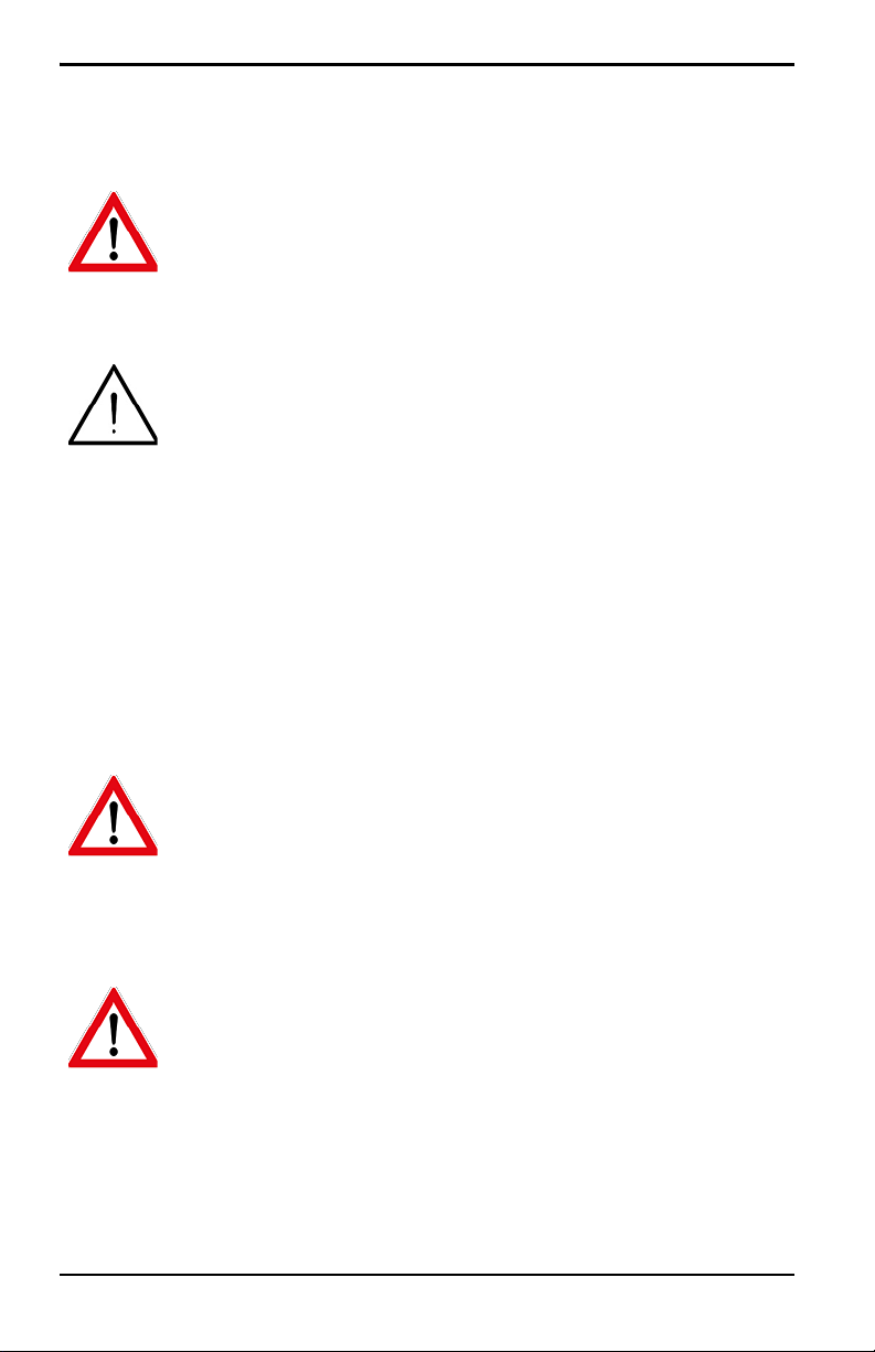
1.1 Introduction
The oxy.IQ Panametrics Oxygen Transmitter (see Figure 1 below) is a
highly reliable and cost-effective two-wire, loop-powered transmitter
with a linearized 4 to 20 mA output. It measures oxygen content in
ten ppm ranges (10, 20, 50, 100, 200, 500, 1000, 2000, 5000 and 10000
ppm) and eight percentage ranges (1, 2, 5, 10, 21, 25, 50 and 100%). All
ranges are user-selectable. This compact transmitter uses proven
sensor technology to accurately measure oxygen content in a variety
of gases, even in hazardous (classified) locations.
Figure 1: oxy.IQ
oxy.IQ User’s Manual 1
Page 12

Chapter 1. Features and Capabilities
1.2 Hazardous Location Certifications
When equipped with an optional Zener barrier or galvanic isolator,
the oxy.IQ can be mounted in a hazardous (classified) location. The
oxy.IQ with Intrinsically Safe option is certified to USA, Canadian,
ATEX, and international IECEx IS requirements. The standard oxy.IQ
is certified to USA, Canadian, EU ATEX and International IECEx
Div2/Zone 2
Non-Incendive requirements.
1.3 Applications
Some typical applications for the oxy.IQ Panametrics oxygen
transmitter include the following:
• Glove box purge and leak detection
• Natural gas
• Semiconductor wafer machines
• Coating process machines
• Membrane air separators
• Inert welding gases
• Pure gaseous hydrocarbon streams
• Process monitoring of gaseous monomers
• Heat treating and bright annealing
2 oxy.IQ User’s Manual
Page 13

Chapter 1. Features and Capabilities
1.4 Features
The oxy.IQ oxygen sensor uses an advanced galvanic fuel cell that
provides superior performance, accuracy, stability and long life. The
cell’s innovative design eliminates the potential for negative signal
output and reduces sources of contamination.
The cell is unaffected by other background gases or hydrocarbons
and is compatible with acidic gases (
from air at low ppm levels takes just a few minutes. Because the cell
is self-contained, minimal maintenance is required. There is no
electrolyte to change and no electrodes to clean.
oxy.IQ offers the following features:
The
OX-2 and OX-4 cells). Recovery
• Two-wire, loop-powered, 4 to 20 mA transmitter
• Display with keypad
• Intrinsically-safe option
• Proven galvanic fuel cell O
sensor technology
2
• User-selectable ranges for ppm and percent oxygen
• User-friendly and intuitive user interface with diagnostics
• Microprocessor-based, all-digital technology for reliable
operation
• Low maintenance, economical and compact
• Sensor failure output error
• Sensor lifetime indication
• NAMUR error indication
oxy.IQ User’s Manual 3
Page 14

Chapter 1. Features and Capabilities
1.5 Sample Systems
In addition to the standard features and options, GE offers a full line
of sample handling systems for a variety of applications. If needed,
GE can design and build a sample conditioning system to meet
unique application requirements. Please contact GE for details.
Table 1 below lists some background gases that can interfere with the
oxygen sensor.
Table 1: Oxygen Sensor Interference Gases
OX-1 & 5 ppm OX-2 ppm OX-3 % OX-4 %
Gas
H2S <5 ppm <10 ppm 0.0005 % 0.01 % 0.001 % 0.1 %
Cont. Cont. Cont. Int. (1) Cont. Int.
SO
SO
<10 ppm <10 ppm 0.01 % 0.1 % 0.01 % 0.1 %
3
<10 ppm (3) 0.01 % 0.1 % (3) (3)
2
HCl <1000 ppm (3) 0.1 % 1.0 % (3) (3)
HCN <1000 ppm (3) 0.1 % 1.0 % (3) (3)
CO
NO
Cl
<1000 ppm (3) 0.1 % 20 & (3) (3)
2
2
2
(2) (2) (2) (2) (2) (2)
(2) (2) (2) (2) (2) (2)
Cont. = Continuous, Int. = Intermittent
(1) Recommended maximum exposure 30 minutes, followed by flushing
with ambient air for an equal period.
(2) Minimal effect on sensor performance, but produces signal interference
of 1:2 ratio for ppm levels only (e.g., 100 ppm NO
looks like 200 ppm
2
O2).
(3) Minimal effect on sensor performance
4 oxy.IQ User’s Manual
Page 15
Chapter 2. Installation
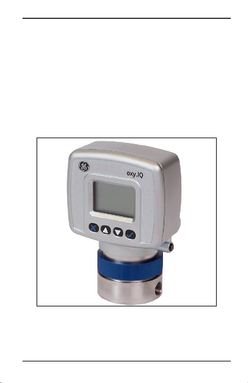
CONNECTOR
1.58
[40.3]
2.05
[52.1]
B
C
2.75
[69.8]
4.10
[104.2]
1.33
[33.9]
A
0.32
[8.25]
1.03
[26.27]
0.53
[13.57]
1.00
[25.40]
2X
1/8-27NPT-2B
.27 [6.9]
2X
8-32 UNC-2B
.51 [12.9] MAX
Ø1.75
[44.3]
Note: All dimensions are inches [mm].
Chapter 2. Installation
2.1 Mounting the oxy.IQ
To install the oxy.IQ into the process or sample system, refer to
Figure 9 on page 38 and/or Figure 2 below and proceed to the next
page.
Figure 2: Outline and Dimensions (ref. dwg. 712-1840)
Note: To avoid collecting condensate that may damage the oxygen
sensor, mount the oxy.IQ in an upright position, with the sensor
manifold below the electronics module.
oxy.IQ User’s Manual 5
Page 16
Chapter 2. Installation
2.1 Mounting the oxy.IQ (cont.)
Install the oxy.IQ by completing the following steps:
1. Remove the oxy.IQ and the separately-packaged oxygen sensor
(see Figure 3 below) from the shipping container. Keep the
shipping container and packaging material for possible future
use.
IMPORTANT: DO NOT open the oxygen sensor package until you are
ready to install the sensor.
Figure 3: Packaged Oxygen Sensor
2. Remove the sensor manifold by unscrewing it from the blue
knurled nut on the sensor base at the bottom of the electronics
module.
6 oxy.IQ User’s Manual
Page 17
Chapter 2. Installation
Sample Inlet Sample Outlet
Sensor Manifold
PTFE Tape
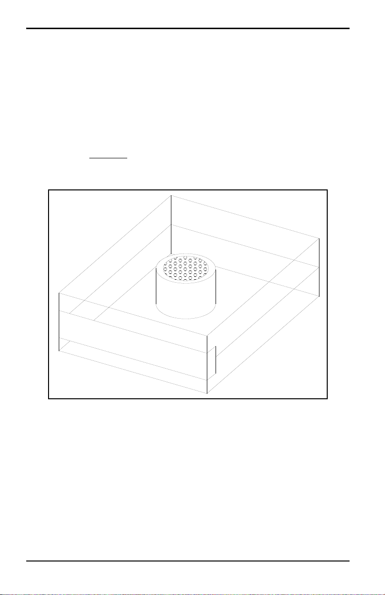
2.1 Mounting the oxy.IQ (cont.)
IMPORTANT: The maximum operating pressure for the oxy.IQ is 10
psi, and the burst pressure of the unit is 200 psi. Be sure
the sample conditioning system is designed to maintain
the oxy.IQ pressure below these limits, and that the
oxy.IQ outlet is vented to atmosphere during operation
and calibration.
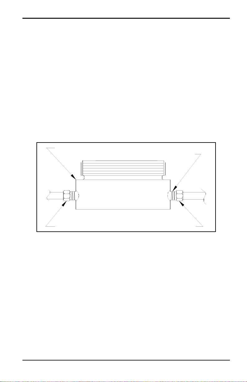
3. Using PTFE tape as a sealant, connect the sample gas inlet and
outlet to the 1/8” NPT ports on the sensor manifold (see Figure 4
below). Either port may be used as the inlet or the outlet, as the
direction of flow does not matter.
Figure 4: Sensor Manifold Installation
oxy.IQ User’s Manual 7
Page 18
Chapter 2. Installation
Cable Connector
Alignment Arrow
Std. Cable
Blank Label
2.2 Wiring the oxy.IQ
To wire the oxy.IQ, refer to Figure 14 on page 43, then proceed as
follows:
WARNING! For IS (Intrinsically Safe) applications, the oxy.IQ
must be installed with a Zener barrier (see the
top of Figure 14 on page 43). Also, for
installations in a hazardous location, the blue IS
cable (p/n 704-1318-02, 10) must be used.
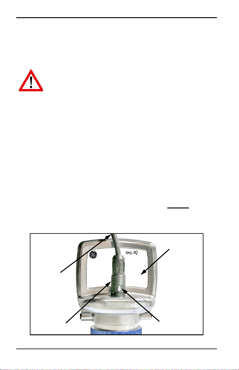
1. Attach the appropriate cable to the oxy.IQ (see Figure 5 below). Be
sure to align the white arrow on the cable connector with the
white arrow on the oxy.IQ connector, and then push the top of the
cable connector straight down onto the mating connector on the
rear of the electronics module until you hear it click into place.
IMPORTANT: Do not rotate the cable connector during installation (it is
not threaded) and do not hold the connector by its
bottom section while pushing it down into place.
IMPORTANT: To remove the cable, grasp the bottom section of the
connector (the part with the white arrow) and pull it
straight up until the cable comes loose.
DO NOT twist the
connector either by hand or with any tool during
removal.
8 oxy.IQ User’s Manual
Page 19

Chapter 2. Installation
Figure 5: oxy.IQ Cable and Connector
2.2 Wiring the oxy.IQ (cont.)
2. Connect the flying lead end of the cable as shown in the wiring
diagram, according to one of the following conditions:
• No Zener Barrier or Galvanic Isolator:
For use in non-hazardous areas or Div 2 hazardous areas.
• With Zener Barrier or Galvanic Isolator:
Required for use in hazardous areas.
IMPORTANT: To remove the cable from the oxy.IQ electronics module,
simply pull straight up on the lower section of the cable
connector as close to the oxy.IQ body as possible. Do not
pull on the cable or the upper portion of the cable
connector, and do not try to unscrew the cable connector.
2.2.1 Longer Cable Lengths
GE offers cables in 2 m and 10 m standard lengths. Longer cable
lengths may be used with the oxy.IQ, but these are not available from
GE. If you require a longer cable, refer to the following figures for the
required cable specifications and construct your own cable for
splicing onto the standard GE cable:
• Standard Cable: Figure 10 on page 39 and Figure 11 on page 40
• IS Cable: Figure 12 on page 41 and Figure 13 on page 42
oxy.IQ User’s Manual 9
Page 20
Chapter 2. Installation
Oxygen Sensor Ring
Knurled Nut
Sensor Base
Sensor Manifold
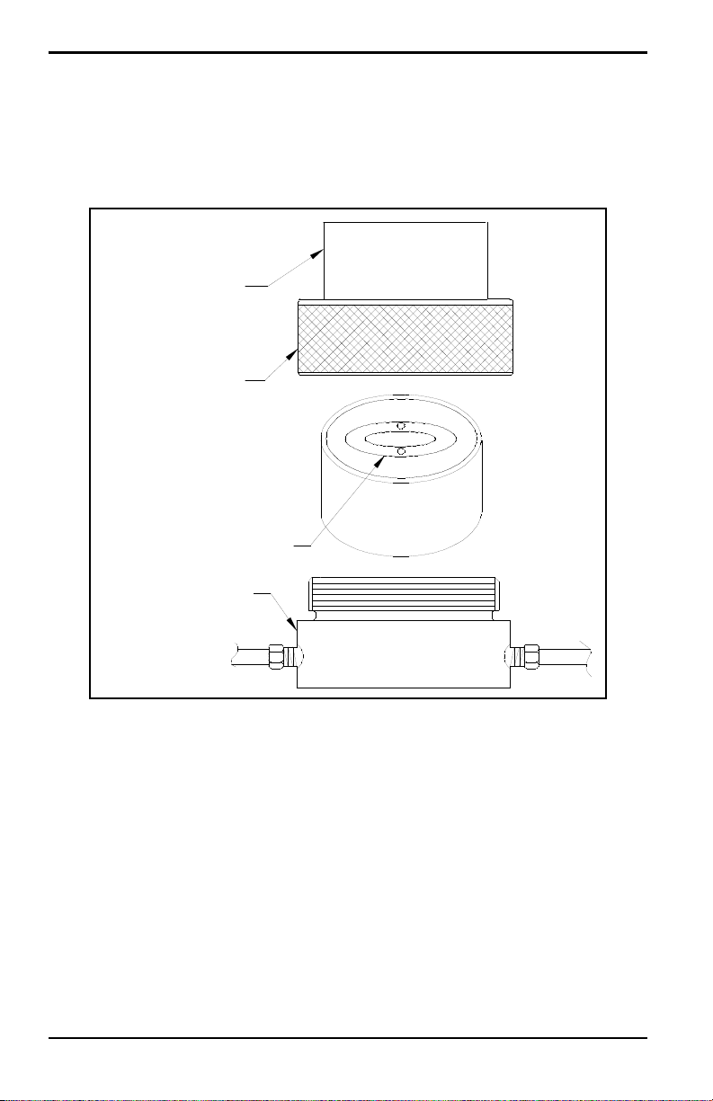
2.3 Installing an Oxygen Sensor
To install a new or replacement oxygen sensor in the oxy.IQ, refer to
Figure 6 below and complete the following steps:
Figure 6: Oxygen Sensor Installation
1. Disconnect the power from the oxy.IQ.
2. Loosen the blue knurled nut and remove the oxy.IQ electronics
module from the sensor manifold. If a previous oxygen sensor is
already in place, remove and discard it.
10 oxy.IQ User’s Manual
Page 21

Chapter 2. Installation
2.3 Installing an Oxygen Sensor (cont.)
3. Apply power to the unit. The screen will display “INITIALIZING
PLEASE WAIT”
measurement data.
Note: Before continuing with the installation, become familiar with the
procedures for programming and calibrating the oxy.IQ
discussed in Chapter 3, Initial Setup & Operation.
4. Trim the 4-20 mA analog output and set the range to 0-25%
oxygen.
5. Open the airtight package (see Figure 3 on page 6) and remove the
oxygen sensor from the package. To maintain the oxygen sensor’s
energy level, remove the red grounding tab and
install the sensor in the oxy.IQ
6. Orient the sensor so that its gold-plated electrodes are facing the
spring-loaded contact pins in the sensor base (see Figure 6 on
page 10). Firmly press the oxygen sensor into the sensor base at
the bottom of the oxy.IQ electronics module.
for a few seconds before it begins to display
immediately
7. Perform an air calibration on the new oxygen sensor at this time.
On the 0-25% oxygen scale, a properly calibrated oxygen sensor
shows a reading of 20.9% on the display and generates a current
of 17.4 mA at the 4-20 mA analog output terminals.
8. Using the blue knurled nut, attach the oxy.IQ electronics module
with the calibrated oxygen sensor to the sensor manifold. Rotate
the display as desired and then hand-tighten the blue knurled
nut.
IMPORTANT: Make sure that the O-ring on the top of the sensor
manifold is in place and undamaged. If necessary,
contact GE for a replacement.
oxy.IQ User’s Manual 11
Page 22

Chapter 2. Installation
2.3 Installing an Oxygen Sensor (cont.)
9. Begin the flow of the process gas. The analog output reading will
drop as the oxygen sensor adjusts to the reduced oxygen level.
During this time, reset the range as required.
10. For improved accuracy in the ppm oxygen ranges, a span gas
calibration should now be performed (see “Span Gas Calibration”
on page 19).
IMPORTANT: Sensor life is dependent on the application. High oxygen
concentrations and contaminants such as acidic gases
will shorten the sensor life.
12 oxy.IQ User’s Manual
Page 23
Chapter 3. Initial Setup & Operation
Down Arrow
Up Arrow
Display
EnterCancel
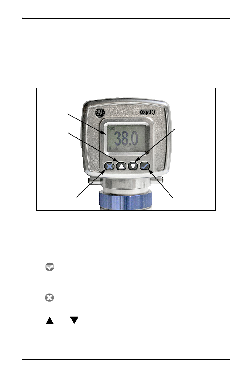
Chapter 3. Initial Setup & Operation
3.1 The oxy.IQ Display and Keypad
All programming of the oxy.IQ is done via the front panel keypad and
display, as illustrated below.
Figure 7: oxy.IQ Display and Keypad
The front panel components perform the following functions:
• Display - Data measurements and the programming menus
and options are shown on the LCD display screen.
• Enter - While in measurement mode, press this key to
enter the Main Menu. While in the Main Menu, press this key
to save an entry and advance to the next screen.
• Cancel - While in the Main Menu, press this key to cancel
an entry and to return to the previous screen.
• and Keys - In the Main Menu, use these keys to move
the cursor between rows one row at a time in the direction
indicated.
oxy.IQ User’s Manual 13
Page 24

Chapter 3. Initial Setup & Operation
3.2 The oxy.IQ Menu Map
As an aid in navigating through the Main Menu, a complete Menu
Map of the user program is shown in Figure 16 on page 46. Refer to
this figure as needed while programming the oxy.IQ.
The oxy.IQ Main Menu consists of the following submenus:
• Calibration Menu (no passcode required)
• Display Menu (no passcode required)
• Output Menu (no passcode required)
• Service Menu (factory service passcode required)
To enter the Main Menu from normal display mode, simply press the
Enter key at any time. To leave the Main Menu and return to
measurement mode, press the
Note: Depending on how deep you are in the menu structure, it may be
necessary to press the
all the way back to measurement mode.
Cancel key.
Cancel key more than once to return
3.3 Adjusting and Calibrating the oxy.IQ
Upon startup, the following five-step adjustment and calibration
procedure must be performed on the oxy.IQ:
1. Select the desired output range.
2. Trim the low (4 mA) and high (20 mA) analog outputs.
3. Upon installation of a new oxygen sensor, calibrate the unit with
air for either a ppm or % sensor.
4. For ppm sensors only, purge the sensor with a low ppm oxygen
gas.
5. For all subsequent calibrations, use a span gas that is appropriate
for the sensor and range selected.
14 oxy.IQ User’s Manual
Page 25
Chapter 3. Initial Setup & Operation
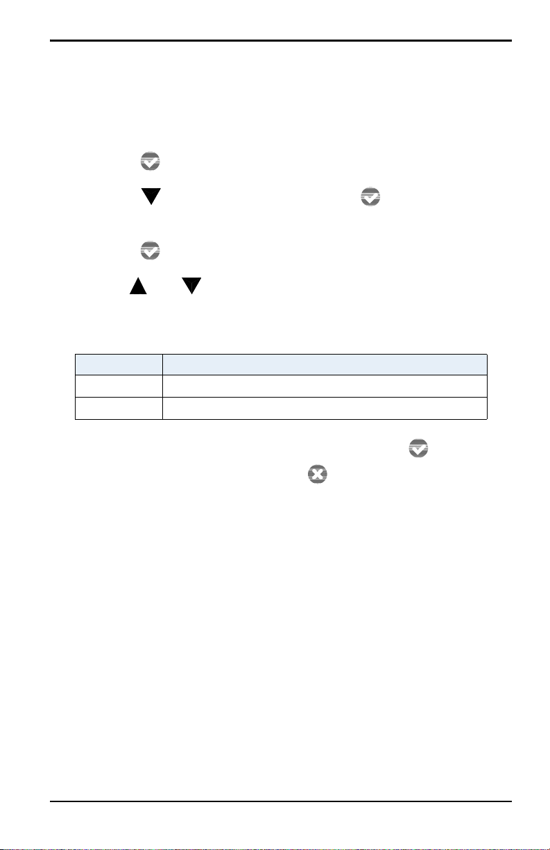
3.3.1 Selecting the Output Range
To select the desired measurement range, complete the following
steps:
1. Press the
2. Press the key twice and then press the
Enter key to enter the Main Menu.
Enter key to enter
the Output menu.
3. Press the
Enter key to select the Range menu option.
4. Use the and keys to scroll through the available options, as
listed in Table 2 below.
Table 2: Available Output Ranges
Units Span Value
% O2 1, 2, 5, 10, 21, 25, 50, 100
ppm O2 10, 20, 50, 100, 200, 500, 1000, 2000, 5000, 10000
5. After selecting the desired output range, press the
save the selection. Then, press the
Cancel key to return to the
Enter key to
Output menu.
oxy.IQ User’s Manual 15
Page 26
Chapter 3. Initial Setup & Operation
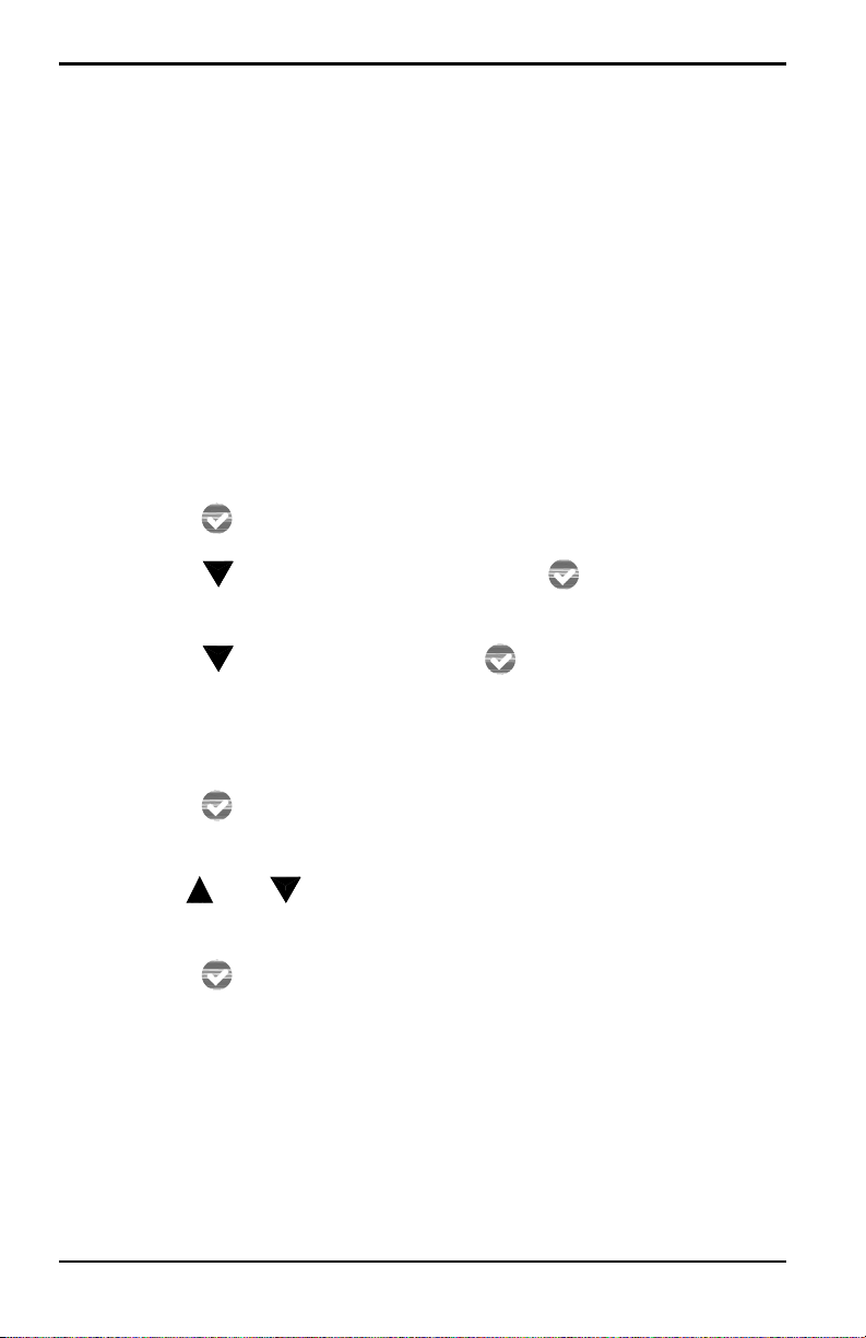
3.3.2 Trimming the Analog Output
To trim the analog output, calibrate the low (4 mA) end of the output
then the high (20 mA) end of the output.
IMPORTANT: The 4 mA and 20 mA adjustments interact with each
other. Therefore, recheck the trim after the procedure has
been completed.
3.3.2a Preparing to Trim the Analog Output
Prepare to trim the analog output as follows:
1. Connect an ammeter in series with the positive oxy.IQ power
supply lead, to monitor the analog output current.
2. Press the
3. Press the key twice and then press the
Enter key to enter the Main Menu.
Enter key to enter
the Output menu.
4. Press the key and then press the
Enter key to enter the
Trim menu.
3.3.2b Trimming the Analog Output Low (4 mA) End
1. Press the Enter key to enter the 4 mA Trim menu, and the
analog output is driven to about 4 mA.
2. Use the and keys to adjust the analog output up or down,
until it equals 4.00 ± 0.01 mA.
3. Press the
the Trim menu.
Enter key to save the trim adjustment and return to
16 oxy.IQ User’s Manual
Page 27
Chapter 3. Initial Setup & Operation
3.3.2c Trimming the Analog Output High (20 mA) End
1. Press the key and then press the Enter key to enter the 20
mA Trim menu, and the analog output is driven to about 20 mA.
2. Use the and keys to adjust the analog output up or down,
until it equals 20.00 ± 0.01 mA.
3. Press the
Enter key to save the trim adjustment and return to
the Trim menu.
3.3.2d Completing the Trim Procedure
1. Repeat both the low (4 mA) end and high (20 mA) end analog
output trimming steps until no further trimming adjustments are
required.
2. Press the
Cancel key twice to return to the Main Menu.
3.3.3 Air Calibration
An air calibration is always recommended upon installation of a new
oxygen sensor. However, because of the non-linearity of the oxygen
sensor, a span gas calibration (see the next section) can also be
performed to ensure a faster and more accurate calibration for the
ppm ranges.
CAUTION! The useful life of ppm sensors is extended by
minimizing exposure of the sensor to air.
To perform an air calibration, complete the following steps:
1. Press the
2. Press the
3. Press the
Enter key to enter the Main Menu.
Enter key to enter the Calibration menu.
Enter key to select the Air menu option.
4. Proceed to the appropriate section, depending on whether you
are calibrating a new sensor or recalibrating an existing sensor.
oxy.IQ User’s Manual 17
Page 28

Chapter 3. Initial Setup & Operation
3.3.3a Calibrating a New Sensor
For a new sensor, continue the air calibration procedure as follows:
1. Press the key and then press the
Enter key to select the
YES menu option.
2. Press the
Enter key to acknowledge that you are resetting the
sensor lifetime clock.
3. As instructed, remove the sensor manifold to expose the new
oxygen sensor to ambient air for about two minutes. Then, press
the
Enter key to continue.
4. A message indicating that the calibration is in progress will be
displayed, and then the calibration data will be shown. At that
time, press the
Enter key to save the calibration data and
return to measurement mode.
Note: A second calibration of the new sensor should be performed
within 1-2 days of the first calibration.
3.3.3b Recalibrating an Existing Sensor
For an existing sensor, continue the air calibration procedure as
follows:
1. Press the
Enter key to select the NO menu option.
2. As instructed, remove the sensor manifold to expose the oxygen
sensor to ambient air for about two minutes. Then, press the
Enter
key to continue.
3. A message indicating that the calibration is in progress will be
displayed, and then the calibration data will be shown. At that
time, press the
Enter key to save the calibration data and
return to measurement mode.
18 oxy.IQ User’s Manual
Page 29

Chapter 3. Initial Setup & Operation
4.0 16.0
Span Gas ppm
Full Range ppm
------------------------ --------------
+ mA Output=
3.3.4 Span Gas Calibration
Before beginning the span gas calibration, make sure the oxy.IQ is
indicating an O
accurate calibration. Then, start the flow of the span gas to the
sensor. For accurate calibration, the span gas should have an oxygen
content of 70-90% of the range being calibrated.
To perform the span calibration, complete the following steps:
1. Use the equation below to calculate the expected mA output that
corresponds to the known oxygen content of the span gas:
For example, if the span gas contains 80 ppm oxygen and the
0-100 ppm range is being calibrated, the analog output should equal
4 + 16 x (80/100) = 16.8 mA.
2. If you have not done so already, start the flow of span gas to the
sensor and allow both the 4-20 mA output reading and the
display reading to stabilize.
level less than the span gas value, to ensure an
2
3. After the reading has stabilized, press the
4. Press the
5. Press the key and then press the
6. Press the and keys until the measurement agrees with the
7. Confirm that the reading on the display has stabilized, and press
oxy.IQ User’s Manual 19
Enter key to enter
the Main Menu.
Enter key to enter the Calibration menu.
Enter key to select the
Span Gas menu option.
span calibration gas value.
the
Enter key to save the calibration. Then, press the Cancel
key twice to return to measurement mode.
Page 30

Chapter 3. Initial Setup & Operation
[no content intended for this page]
20 oxy.IQ User’s Manual
Page 31

Chapter 4. User Programming
Chapter 4. User Programming
4.1 Introduction
IMPORTANT: The oxy.IQ Service menu is for use by qualified service
personnel only and requires a special passcode for
access. That menu is not discussed in this chapter.
This chapter provides instructions for programming all of the oxy.IQ
menu options available to the user, which can be accessed without
the use of a passcode. These menu options are found in the following
Main Menu submenus:
• Calibration Menu
• Display Menu
• Output Menu
While programming these menus, refer to the menu map in Figure 16
on page 46.
Note: The menu options for initial setup are described in Chapter 3,
Initial Setup & Operation, and are only referenced in this
chapter.
4.2 The Calibration Menu
Proceed to the appropriate section to program the desired menu
option.
4.2.1 Air
See “Air Calibration” on page 17.
4.2.2 Span Gas
See “Span Gas Calibration” on page 19.
oxy.IQ User’s Manual 21
Page 32

Chapter 4. User Programming
4.2.3 Sensor Life
To read the sensor life, complete the following steps:
1. Press the
2. Press the
3. Press the key three times and then press the
Enter key to enter the Main Menu.
Enter key to enter the Calibration menu.
Enter key to
enter the Sensor Life menu.
4. The number of days your sensor has been in use is displayed.
When you have finished reading the information, press the
Enter
key to return to the Calibration menu.
5. Press the
Cancel key twice to return to measurement mode.
22 oxy.IQ User’s Manual
Page 33

Chapter 4. User Programming
4.3 The Display Menu
Proceed to the appropriate section to program the desired menu
option.
4.3.1 Select the O2 Parameter
To select the O2 parameter for display, complete the following steps:
1. Press the
2. Press the key once and then press the
the Display menu.
3. Press the
4. Use the and keys to select the desired O2 range to be
displayed:
Enter key to enter the Main Menu.
Enter key to enter
Enter key to enter the O2 menu.
• ppm only
• % only
• Auto Select (automatically displays the appropriate range)
5. Press the
measurement mode.
Enter key to confirm your choice and return to
oxy.IQ User’s Manual 23
Page 34

Chapter 4. User Programming
4.3.2 Display the Sensor Range
To select whether or not the O2 range of the installed sensor is
displayed, complete the following steps:
1. Press the
2. Press the key once and then press the
Enter key to enter the Main Menu.
Enter key to enter
the Display menu.
3. Press the key once and then press the
Enter key to enter
the Display Range menu.
4. Use the and keys to select the desired option:
• On - the O2 range is displayed at the bottom of the screen
• Off - the O2 range is not displayed at the bottom of the screen
5. Press the
measurement mode.
4.3.3 Adjust the Contrast
To adjust the display contrast, complete the following steps:
1. Press the
2. Press the key twice and then press the
the Contrast menu.
Enter key to confirm your choice and return to
Enter key to enter the Main Menu.
Enter key to enter
3. Use the and keys to adjust the contrast to the desired
value, then press the
4. Press the
24 oxy.IQ User’s Manual
Cancel key twice to return to measurement mode.
Enter key to save the new value.
Page 35

Chapter 4. User Programming
4.4 The Output Menu
Proceed to the appropriate section to program the desired menu
option.
4.4.1 Range
See “Selecting the Output Range” on page 15.
4.4.2 Trim
See “Trimming the Analog Output” on page 16.
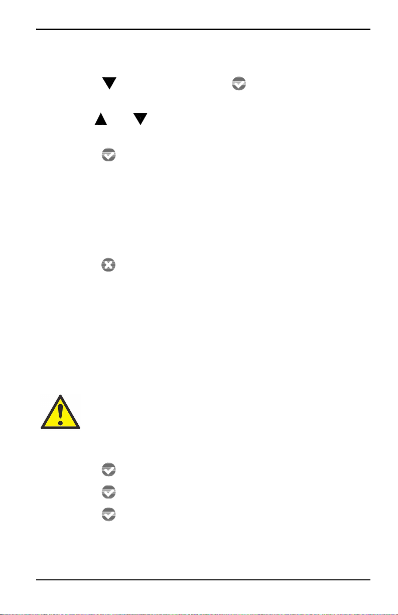
4.4.3 Error Type
To select the process conditions that will activate an on-screen
warning and send an alarm to the analog output device, complete the
following steps:
1. Press the
Enter key to enter the Main Menu.
2. Press the key twice and then press the
the Output menu.
3. Press the key twice and then press the
the Error Type menu.
Enter key to enter
Enter key to enter
oxy.IQ User’s Manual 25
Page 36

Chapter 4. User Programming
4.4.3 Error Type (cont.)
4. Use the and keys to select the desired option and then
press the
will appear next to the selected option to indicate that it is
activated. The following options are available, and you may
activate as many of these options as you wish.
Note: Only the first four options are displayed on the screen upon
entering this menu. When you scroll down to the fourth option
(Low Temp), a down arrow to the right of this option indicates
that an additional screen of options is available.
Enter key to activate that error type. A check mark
• High O2
• Low O2 (programmable)
• High Temp
• Low Temp (programmable)
• Temp Comp (listed on second screen of options)
Note: Pressing the Enter key on an error type that has already been
activated, will deactivate that option and remove the check
mark.
5. Press the
mode.
26 oxy.IQ User’s Manual
Cancel key three times to return to measurement
Page 37

Chapter 4. User Programming
4.4.4 Error Output
To select the desired output value that will be sent to the analog
output device upon an error, complete the following steps:
1. Press the
2. Press the key twice and then press the
the Output menu.
3. Press the key three times and then press the
enter the Error Output menu.
4. Use the and keys to select the desired option and then
press the
will appear next to the selected option to indicate that it is
activated. The following options are available, and you may
activate only one option at a time.
Note: Only the first four options are displayed on the screen upon
entering this menu. When you scroll down to the fourth option
NAMUR), a down arrow to the right of this option indicates that
(
an additional screen of options is available.
Enter key to enter the Main Menu.
Enter key to enter
Enter key to
Enter key to activate that error output. A check mark
• None (no error output is generated)
• Low (an output of 4 mA is generated)
• High (an output of 20 mA is generated)
• Value (an error output at a programmable fixed value is
generated)
• NAMUR (listed on second screen of options)
Note: Pressing the Enter key on a different error output will
automatically deselect any previously selected output.
5. Press the
mode.
oxy.IQ User’s Manual 27
Cancel key three times to return to measurement
Page 38

Chapter 4. User Programming
[no content intended for this page]
28 oxy.IQ User’s Manual
Page 39

Chapter 5. The Service Menu
Chapter 5. The Service Menu
CAUTION! The Service Menu is intended for use by
qualified service personnel only, and access to this menu
requires entry of the service passcode. Misuse of the
information in this menu may significantly impair the
accuracy and performance of your oxy.IQ and may cause
it to fail to meet its published specifications.
5.1 Menu Map & Service Passcode
For help in navigating through the Service Menu, refer to the menu
map shown in Figure 17 on page 47. The service passcode required for
access to the oxy.IQ Service Menu is:
7378
5.2 Entering the Service Menu
To enter the Service Menu, complete the following steps:
1. Press the
2. Press the key three times and then press the
Enter key to enter the Main Menu.
Enter key to
select the Service menu.
3. Use the and keys to increment or decrement the displayed
value (default = 5000) to enter the service passcode, and then
press the
Note: When entering the passcode, press and release an arrow key to
Enter key to access the Service menu.
change the value one digit at a time, or press and hold an arrow
key to change the value at an accelerating rate.
4. Proceed to the appropriate section for the desired menu option.
oxy.IQ User’s Manual 29
Page 40

Chapter 5. The Service Menu
5.2.1 Diagnostics
To enter the Diagnostics menu option from the Service Menu,
complete the following steps:
1. Use the and keys as necessary to highlight the Diagnostics
menu option.
2. Press the
3. Page 1 of the Diagnostics option displays the current values for
the following parameters:
Enter key to enter the Diagnostics menu.
• O2 A
• Output mA
• Output %
When you have finished reading the information, press the
key to move to Page 2 of the Diagnostics menu or press the
key to exit the Diagnostics menu.
4. Page 2 of the Diagnostics option displays the current values for
the following parameters:
Enter
Cancel
• Temp °C
• Temp Res
• Gain
• OX-n (currently installed sensor type, n = 1, 2, 3 or 4)
When you have finished reading the information, press the
key to move to Page 1 of the Diagnostics menu or press the
key to exit the Diagnostics menu.
5. Press the
30 oxy.IQ User’s Manual
Cancel key twice to return to measurement mode.
Enter
Cancel
Page 41

Chapter 6. Specifications
Chapter 6. Specifications
6.1 Intrinsically Safe (IS) Installation
Intrinsically safe installations require an MTL7706 zener barrier,
one IS cable, and one non-IS cable.
Power Requirements
24 to 28 VDC at 50 mA
Cable
p/n 704-1318-02 (2 m length) or p/n 704-1317-10 (10 m length)
blue jacketed, twisted-pair with connector, 26 AWG conductors,
with connector
Output
Total load must equal 250 ±5% when using a zener barrier
6.2 Non-Incendive (Div 2) and General Purpose Installation
No zener barrier or galvanic isolator is used.
Power Requirements
9 to 28 VDC, loop-powered, 0.7 W max
Cable
p/n 704-1317-02 (2 m length) or p/n 704-1317-10 (10 m length)
black jacketed, twisted-pair with connector, 26 AWG conductors,
with connector
oxy.IQ User’s Manual 31
Page 42

Chapter 6. Specifications
6.3 All Installations
Process Wetted Materials
SS process unit: 316 stainless steel, Viton
electrical contacts, and glass
User-Selectable Measurement Ranges
• PPM sensors:
- 0 to 10 ppm
- 0 to 20 ppm
- 0 to 50 ppm
- 0 to 100 ppm
- 0 to 200 ppmv O
- 0 to 500 ppmv O
- 0 to 1000 ppmv O
- 0 to 2000 ppmv O
- 0 to 5000 ppmv O
- 0 to 10,000 ppmv O
(OX-1 or OX-2 only)
v O2
(OX-1 or OX-2 only)
v O2
(OX-1 or OX-2 only)
v O2
v O2
2
2
2
2
2
2
®
O-ring, gold-plated sensor
• Percent sensors:
- 0% to 1% O
- 0% to 2% O
- 0% to 5% O
- 0% to 10% O
- 0% to 25% O
- 0% to 50% O
Accuracy
2
2
2
2
2
2
• ±1% of range at calibration point
• ±2% of range at the calibration point for the
0 to 10 ppm
32 oxy.IQ User’s Manual
range (OX-1, 2)
v O2
Page 43

6.3 All Installations (cont.)
Repeatability
• ±1% of range
Chapter 6. Specifications
• ±2% of range for the 0 to 10 ppm
Resolution
±0.1% of range
Linearity
range (OX-1, 2)
v O2
• ±2% of range (OX-1, 2, 3, 5)
• ±5% of range (OX-4)
Sensor Operating Temperature
O
2
32°F to 113°F (0°C to 45°C)
Sample Pressure
Vented to atmosphere during operation and calibration
Atmospheric Pressure Effect
±0.13% of reading per mmHg (directly proportional to absolute
pressure)
Note: During calibration, pressure and flow must be kept constant.
Process Connections
1/8” NPT-F inlet and outlet
Dimensions
4.10 x 2.75 x 2.05 in. (104.1 x 69.9 x 52.1 mm)
Weight
1.35 lb (612 grams)
oxy.IQ User’s Manual 33
Page 44

Chapter 6. Specifications
6.3 All Installations (cont.)
Sample Flow Rate
1.0 SCFH (500 cc/min) recommended for process units
Electrical Classification
Intrinsically Safe package with zener barrier or galvanic isolator:
• USA/Canada:
IS for Class I, Div 1, Groups A, B, C, D; T4
IS for Class I, Zone 0, AEx ia IIC T4; Tamb -20 to +60°C
• EU ATEX:
II 1 G ia IIC Ga
IECEx Ex ia IIC T4; Tamb -20 to +60°C
Intrinsically safe package for non-incendive (Div 2) application
without use of zener barrier or galvanic isolator:
• USA/Canada:
Class I, Div. 2, Groups A, B, C, D; T4
• ATEX/IECEx:
Ex na IIC T4
European Compliance
See the EU Declaration of Conformity at the back of this manual
34 oxy.IQ User’s Manual
Page 45

6.4 Product Label
II 1 G
A typical product label is shown in Figure 8 below:
Figure 8: oxy.IQ Label - IS Package Option
Chapter 6. Specifications
oxy.IQ User’s Manual 35
Page 46

Chapter 6. Specifications
[no content intended for this page]
36 oxy.IQ User’s Manual
Page 47

Appendix A. Outline and Installation Drawings
Appendix A. Outline and Installation Drawings
This appendix includes the following oxy.IQ drawings:
• “Outline & Installation (ref. dwg. 712-1840)” on page 38
• “Cable, Standard (ref. dwg. 704-1317, SH 1 of 2)” on page 39
• “Cable, Standard (ref. dwg. 704-1317, SH 2 of 2)” on page 40
• “Cable, IS (ref. dwg. 704-1318, SH 1 of 2)” on page 41
• “Cable, IS (ref. dwg. 704-1318, SH 2 of 2)” on page 42
• “Wiring Options (ref. dwgs. 702-285 & 702-286)” on page 43
• “Schematic Diagram (ref. dwg. 752-347)” on page 44
oxy.IQ User’s Manual 37
Page 48

Appendix A. Outline and Installation Drawings
CONNECTOR
1.58
[40.3]
2.05
[52.1]
B
C
2.75
[69.8]
4.10
[104.2]
1.33
[33.9]
A
0.32
[8.25]
1.03
[26.27]
0.53
[13.57]
1.00
[25.40]
2X
1/8-27NPT-2B
.27 [6.9]
2X
8-32 UNC-2B
.51 [12.9] MAX
Ø1.75
[44.3]
NOTES:
1. WEIGHT: 1.35 lb [612.3 g]
2. COLOR: METALLIC
3. DIMENSIONS: inches [mm]
A
Ø .03 [.76] Ø .03 [.76]
BC ABC
Figure 9: Outline & Installation (ref. dwg. 712-1840)
38 oxy.IQ User’s Manual
Page 49

.25±.03
XX
1.16
1.00±.25
AA
1
2
3
BLUE
BROWN
4
1
2
4
3
.49
INDICATOR
ARROW
1.00
SECTION A-A
SCALE 2 : 1
3
CABLE LENGTH
5
HEAT SHRINK
WITH ADHESIVE BACKING
XX-CABLE LENGTH
PART NUMBER
EXTENSION
2 METERS -0/.1 (6.56FT -0/+.33)
02
10 METERS -0/.5 (32.81FT -0/+1.58)
10
NOTES:
1. INTERPET DRAWING IN ACCORDANCE WITH ASME Y14.5(M)-2009
2. FINISHED COMPONENTS TO BE ROHS COMPLIANT
3. PART TO BE CLEAN OF DIRT/DEBRIS
4. PERFORMANCE SPECIFICATION
RATED CURRENT 2.0 A
RATED VOLTAGE 24 VDC
OPERATING TEMPERATURE RANGE -25 C TO 85 C
PROTECTION CLASS MEETS NEMA TYPE 1,3,4,6P AND IEC IP67
RETENTION 6.75 lbs. MIN. PERPENDICULAR & NORMAL
5. CABLE ASSEMBLY SHALL BE TESTED 100% FOR CONTINUITY AND SHORTS.
HIROSE SOLDER & BACK SHELL TIGHTENING FIXTURE SHOWN ON SHEET 2.
6. INSPECTION REQUIREMENTS:
ALL CTQs (1-11) IDENTIFIED & NOTES ARE TO BE REPORTED ON THE FAI & MEET AQL .65 LEVEL II PER LOT
SPECIFIC CTQs IDENTIFIED BELOW ARE TO HAVE A CpK NO LESS THAN 1.33:
1,2,4,10
SPECIFIC CTQs IDENTIFIED BELOW ARE TO HAVE A Cp NO LESS THAN 1.33:
@LSL - NONE @USL - NONE
ATTRIBUTE DATA TO MEET 4 SIGMA (0.63% DPMO)IDENTIFIED BELOW:
NONE
Cp & CpK, DPMO DATA TO BE SUPPLIED ELECTRONICALLY OR HARD COPY PER LOT
Appendix A. Outline and Installation Drawings
oxy.IQ User’s Manual 39
Figure 10: Cable, Standard (ref. dwg. 704-1317, SH 1 of 2)
Page 50

Appendix A. Outline and Installation Drawings
1
2.500±.125
X±1
BB
D
C
BLUE & BROWN
PRIMARIES ONLY
EXIT HEAT SHRINK
HIROSE SOLDER FIXTURE
P/N HR30-6P-6S-T01
BACK SHELL
TIGHTENING COLLAR
PLUG INSULATOR
BODY
PUSH/PULL
LOCKING
COLLAR
SPRING
BACK SHELL
GROOVE
SEALING
BUSHING
PLASTIC
COMPRESSION
FITTING
6
6
8
SECTION B-B
1
2
3
4
5
6
.195±.020
.100±.020
DETAIL D
SCALE 2 : 1
WIRE COLOR TO LOCATION LEGEND
1=BROWN, PVC, 26 AWG 7/34
2=WHITE, PVC, 26 AWG 7/34
3=BLUE, PVC, 26 AWG 7/34
4=BLACK, PVC, 26 AWG 7/34
5=DRAIN, PVC, 26 AWG 7/34
6=EMPTY
CABLE LENGTH
9
10
11
XX-CABLE LENGTH
PART NUMBER
EXTENSION
2 METERS (6.56FT)
02
10 METERS (32.81FT)
10
HIROSE
P/N HR30-6P-T02
NOTES:
1. CUT CABLE TO DESIRED LENGTH ACCORDING TO LENGTH TABLE SHOWN.
2. CUT PRIMARIES & DRAIN EXCLUDING BROWN & BLUE BACK TO JACKET AS SHOWN.
3. STRIP & TIN WIRES USING LEAD FREE SODER AT END "B" , BLUE & BROWN, TO A LENGTH OF .250" AS SHOWN.
4. STRIP & TIN WIRES USING LEAD FREE SOLDER AT END "A", 4 PRIMARIES & DRAIN, TO A LENGTH OF .100" AS SHOWN
& TINNED WIRE CONDUCTORS NOT TO EXCEED .020".
5. INSERT INSULATOR BODY OVER THE SOLDER TERMINATION FIX TURE.
6. INSERT PRE SOLDERED CONDUCTORS, ITEMS 1-5, IN THE CONTACT SOLDERING POT
AND SOLDER (IRON TEMPERATURE 280 C 10 C) USING LEAD FREE SOLDER.
IN THEIR RESPECTIVE NUMERICAL LOCATION ACCORDING TO THE COLOR LEGEND.
7. INSPECT SOLDER TERMINATIONS ON END "A" AND TRIM ANY LOOSE STRANDS & ELIMINATE ANY SOLDER BRIDGING.
8. PUSH COMPONENTS DOWN AND TIGHTEN BACK SHELL USING HIROSE FIXTURE SHOWN.
TO PREVENT ACCIDENTAL LOOSENING OF THE BACK SHELL PLACE A SMALL AMOUNT OF PRIMER
(LOCTITE 7649) AND ADHESIVE (LOCTITE 271) IN THREADS. TORQUE TO 0.5 N-m
Figure 11: Cable, Standard (ref. dwg. 704-1317, SH 2 of 2)
40 oxy.IQ User’s Manual
Page 51

.25±.03
XX
1.16
1.00±.25
AA
BLUE
BROWN
1
2
3
1
2
4
3
.49
INDICATOR
ARROW
1.00
3
CABLE LENGTH
4
5
HEAT SHRINK
WITH ADHESIVE BACKING
XX-CABLE LENGTH
PART NUMBER
EXTENSION
2 METERS -0/.1 (6.56FT -0/+.33)
02
10 METERS -0/.5 (32.81FT -0/+1.58)
10
NOTES:
1. INTERPET DRAWING IN ACCORDANCE WITH ASME Y14.5(M)-2009
2. FINISHED COMPONENTS TO BE ROHS COMPLIANT
3. PART TO BE CLEAN OF DIRT/DEBRIS
4. PERFORMANCE SPECIFICATION
RATED CURRENT 2.0 A
RATED VOLTAGE 24 VDC
OPERATING TEMPERATURE RANGE -25 C TO 85 C
PROTECTION CLASS MEETS NEMA TYPE 1,3,4,6P AND IEC IP67
RETENTION 6.75 lbs. MIN. PERPENDICULAR & NORMAL
5. CABLE ASSEMBLY SHALL BE TESTED 100% FOR CONTINUITY AND SHORTS.
HIROSE SOLDER & BACK SHELL TIGHTENING FIXTURE SHOWN ON SHEET 2.
6. INSPECTION REQUIREMENTS:
ALL CTQs (1-11) IDENTIFIED & NOTES ARE TO BE REPORTED ON THE FAI & MEET AQL .65 LEVEL II PER LOT
SPECIFIC CTQs IDENTIFIED BELOW ARE TO HAVE A CpK NO LESS THAN 1.33:
1,2,4
SPECIFIC CTQs IDENTIFIED BELOW ARE TO HAVE A Cp NO LESS THAN 1.33:
@LSL - NONE @USL - NONE
AT TRIBUTE DATA TO MEET 4 SIGMA (0.63% DPMO)IDENTIFIED BELOW:
NONE
Cp & CpK, DPMO DATA TO BE SUPPLIED ELECTRONICALLY OR HARD COPY PER LOT
Appendix A. Outline and Installation Drawings
oxy.IQ User’s Manual 41
Figure 12: Cable, IS (ref. dwg. 704-1318, SH 1 of 2)
Page 52

Appendix A. Outline and Installation Drawings
1
2.500±.125
X±1
BB
D
C
BLUE & BROWN
PRIMARIES ONLY
EXIT HEAT SHRINK
HIROSE SOLDER FIXTURE
P/N HR30-6P-6S-T01
TIGHTENING COLLAR
PLUG INSULATOR
BODY
PUSH/PULL
LOCKING
COLLAR
SPRING
BACK SHELL
GROOVE
SEALING
BUSHING
PLASTIC
COMPRESSION
FITTING
6
7
8
SECTION B-B
1
2
3
4
5
6
.100±.020
.195±.020
DETAIL D
SCALE 2 : 1
.250±.020
DETAIL C
SCALE 2 : 1
WIRE COLOR TO LOCATION LEGEND
1=BROWN, PVC, 26 AWG 7/34
2=WHITE, PVC, 26 AWG 7/34
3=BLUE, PVC, 26 AWG 7/34
4=BLACK, PVC, 26 AWG 7/34
5=DRAIN, PVC, 26 AWG 7/34
6=EMPTY
CABLE LENGTH
9
10
11
XX-CABLE LENGTH
PART NUMBER
EXTENSION
2 METERS (6.56FT)
02
10 METERS (32.81FT)
10
BLACK SHELL HIROSE
P/N HR30-6P-T02
NOTES:
1. CUT CABLE TO DESIRED LENGTH ACCORDING TO LENGTH TABLE SHOWN.
2. CUT PRIMARIES & DRAIN EXCLUDING BROWN & BLUE BACK TO JACKET AS SHOWN.
3. STRIP & TIN WIRES USING LEAD FREE SODER AT END "B" , BLUE & BROWN, TO A LENGTH OF .250" AS SHOWN.
4. STRIP & TIN WIRES USING LEAD FREE SOLDER AT END "A", 4 PRIMARIES & DRAIN, TO A LENGTH OF .100" AS SHOWN
& TINNED WIRE CONDUCTORS NOT TO EXCEED .020".
5. INSERT INSULATOR BODY OVER THE SOLDER TERMINATION FIX TURE.
6. INSERT PRE SOLDERED CONDUCTORS, ITEMS 1-5, IN THE CONTACT SOLDERING POT
AND SOLDER (IRON TEMPERATURE 280 C 10 C) USING LEAD FREE SOLDER.
IN THEIR RESPECTIVE NUMERICAL LOCATION ACCORDING TO THE COLOR LEGEND.
6. INSPECT SOLDER TERMINATIONS ON END "A" AND TRIM ANY LOOSE STRANDS & ELIMINATE ANY SOLDER BRIDGING.
7. PUSH COMPONENTS DOWN AND TIGHTEN BACK SHELL USING HIROSE FIXTURE SHOWN.
TO PREVENT ACCIDENTAL LOOSENING OF THE BACK SHELL PLACE A SMALL AMOUNT OF PRIMER
(LOCTITE 7649) AND ADHESIVE (LOCTITE 271) IN THREADS. TORQUE TO 0.5 N-m
42 oxy.IQ User’s Manual
Figure 13: Cable, IS (ref. dwg. 704-1318, SH 2 of 2)
Page 53

Maximum load of analog input device is
dependent on power supply voltage
and cable resistance.
Maximum load of analog input device is
dependent on power supply voltage
and cable resistance.
1. For Class 1 Div 2 installation, the oxy.IQ shall be installed in
an appropriately rated final enclosure accepting a Division 2
wiring method per NEC/CEC.
oxy.IQ Transmitter
704-1317-xx
(Black Jacket)
Class 1 Div 2 Enclosure
Hazardous Location Non-Hazardous Location
BLUE
BROWN
BROWN
+24V
24V RETURN
POWER SUPPLY
4-20MA ANALOG
INPUT DEVICE
oxy.IQ Transmitter
704-1317-xx
(Black Jacket)
BLUE
BROWN
BROWN
4-20MA ANALOG
INPUT DEVICE
+24V
24V RETURN
POWER SUPPLYNon-Hazardous Location
Hazardous Location Non-Hazardous Location
oxy.IQ Transmitter
IS Cable
704-1318-xx
(Blue Jacket)
+24V
24V RETURN
POWER SUPPLY
4-20MA ANALOG
INPUT DEVICE
R1
R2
ZBB BUS BAR
MTL7706
BLACK
BLACK
GREEN
BLUE
BROWN
IS GROUND
Non-IS Cable
RED
GREEN
1
3
42
1. Equipment connected to barrier
inputs must not use or generate
more than 250V.
2. Total load of R1 + R2 must equal
250 ohms ±5%.
Appendix A. Outline and Installation Drawings
Figure 14: Wiring Options (ref. dwgs. 702-285 & 702-286)
oxy.IQ User’s Manual 43
Page 54

Appendix A. Outline and Installation Drawings
HAZARDOUS OR NON-HAZARDOUS LOCATION
CLASS I, DIVISION 1, GROUP ABCD
CLASS 1, ZONE 0, GROUP IIC
NON-HAZARDOUS LOCATION
oxy.IQ
LOOP TERMINAL
SAFETY ENTITY PARAMETERS:
Ui (Vmax) = 28 V
Ii (Imax) = 150 mA
&L Ƅ)
Li = 0 mH
Pi (Pmax)= 1.05 W
Loop-Power Device
Note 4
Associated Apparatus
Note 3
blue
brown
brown
blue
Loop-Power Device
Note 4
oxy.IQ
Oxygen
Transmitter
HAZARDOUS OR NON-HAZARDOUS LOCATION
CLASS I, DIVISION 2, GROUP ABCD
NON-HAZARDOUS LOCATION
Note 11
NOTES
1. INSTALLATION:
A. INSTALLATIONS IN THE US SHOULD BE IN ACCORDANCE WITH ANSI/ISA RP12.06.01 "INSTALL ATION OF INTRINSICALLY SAFE SYSTEMS FOR HAZARDOUS (CLASSIFIED) LOCATIONS" AND THE LATEST
EDITION OF THE NATIONAL ELECTRICAL CODE (ANSI/NFPA 70)
B. INSTALLATION IN CANADA SHOULD BE IN ACCORDANCE WITH THE LATEST EDITION OF THE C22.1 CANADIAN
ELECTRICAL CODE, PART I.
C. INSTALLATIONS IN EUROPE SHALL BE IN ACCORDANCE WITH LATEST EDITIONS OF THE WIRING PRACTICES FOR THE COUNTRY OF ORIGIN AND EN 60079-14.
D. INSTALLATIONS FOR IECEx CERTIFICATION SHALL BE IN ACCORDANCE WITH LATEST EDITIONS OF THE WIRING PRACTICES FOR THE COUNTRY OF ORIGIN.
2. THE SUBJECT EQUIPMENT IS FM APPROVED AND FM APPROVED FOR CANADA FOR THE FOLLOWING HAZARDOUS
(CLASSIFIED) LOCATIONS AND PROTECTION METHODS:
CLASS 1, DIVISION 1, GROUP ABCD, T4
Tamb: -20 C to +60 C
3. ZENER BARRIER OR GALVANICALLY ISOLATED FM APPROVED (US) OR CANADIAN CERTIFIED (FOR CANADA) ASSOCIATED APPARATUS INSTALLED IN ACCORDANCE WITH THE MANUFACTURER'S INSTRUCTIONS.
4. THE CONTROL ROOM EQUIPMENT CONNECTED TO ASSOCIATED APPARATUS MUST NOT GENERATE MORE THAN 250 Vrms OR VDC OR THE MARKED Um ON THE ASSOCIATED APPARATUS, WHICHEVER IS LESS.
5. MAINTAIN THE FOLLOWING RELATIONSHIP BETWEEN INTRINSIC SAFETY (ENTITY) PARAMETERS OF oxy.IQ AND ASSOCIATED APPARATUS:
R[\,48L9PD[DVVRFLDWHGDSSDUDWXV8R9RF
R[\,4,L,PD[DVVRFLDWHGDSSDUDWXV,R,VF
R[\,43L3PD[DVVRFLDWHGDSSDUDWXV3R
R[\,4&L&FDEOHDVVRFLDWHGDSSDUDWXV&R&D
R[\,4/L/FDEOHDVVRFLDWHGDSSDUDWXV/R/D
6. RESISTANCE BETWEEN INTRINSICALLY SAFE GROUND AND EARTH GROUND SHALL BE LESS THAN 1 OHM.
7. WARNING - TO PREVENT IGNITION OF FLAMMABLE OR COMBUSTIBLE ATMOSPHERES, DISCONNECT POWER BEFORE SERVICING.
AVERTISSEMENT - Pour éviter l'inflammation d'atmosphères inflammables ou combustibles, débrancher l'alimentation avant l'entretien.
8. WARNING - SUBSTITUTION OF COMPONENTS MAY IMPAIR INTRINSIC SAFETY.
AVERTISSEMENT - Remplacement des composants peut compromettre la sécurité intrinsèque.
9. THE ASSOCIATED APPARATUS MUSTE BE ATEX CERTIFIED FOR INSTALLATIONS IN EUR OPE.
10. THE ASSOCIATED APPARATUS MUSTE BE IECEx CERTIFIED FOR IECEx INSTALLATIONS .
11. WHEN INSTALLED IN A DIVISION 2 LOCATION THE MODEL oxy.IQ OXYGEN TRANSMIT TER SHALL BE INSTALLED IN A FINAL ENCLOSURE ACCEPTING A DIVISION 2 WIRING METHOD PER THE NEC / CEC.
Figure 15: Schematic Diagram (ref. dwg. 752-347)
44 oxy.IQ User’s Manual
Page 55

Appendix B. Menu Maps
Appendix B. Menu Maps
This appendix includes the oxy.IQ User Menu Maps (please note the
Service Menu Map is available to qualified BHGE field service
personnel only).
oxy.IQ User’s Manual 45
Page 56

Appendix B. Menu Maps
Main Menu
Display
Output
Service
Range
Span Value
Trim
Error Type
High O2
Low O2
High Temp
Low Temp
O2
ppm only
% only
Display Range
Contrast
Enter Value
Air
Span Gas
Sensor Life
Use Days
Flow Span Gas
None
Error Output
Service Passcode
Required
Calibration
No
Yes
Auto Select
On
Off
Low
High
Value
4 mA Trim
20 mA Trim
Temp Comp
NAMUR
Figure 16: User’s Menu Map
46 oxy.IQ User’s Manual
Page 57

Main Menu
Display
Output
Service
Diagnostics
Temp °C
Temp Res
Gain
Output %
Calibration
O2 uA
Output mA
See User's Menu Map (no passcode required)
Sensor Type
OX-1
OX-2
OX-3
OX-4
OX-n (n=1-4)
Appendix B. Menu Maps
Figure 17: Service Menu Map
oxy.IQ User’s Manual 47
Page 58

Appendix B. Menu Maps
[no content intended for this page]
48 oxy.IQ User’s Manual
Page 59

Appendix C. Order String
Appendix C. Order String
oxy.IQ BCD-E
AModel Only
oxy.IQ Oxygen Transmitter; 4 to 20 mA output
BSensor
0 No sensor
1 Standard ppm, 0 to 10, 20, 50, 100, 200, 500, 1000 ppm
2 Acid ppm, 0 to 10, 20, 50, 100, 200, 500, 1000 ppm
3 Standard percent sensor
4 Acid percent sensor
5 Standard ppm, 0 to 100, 200, 500 and 1000 ppm
CPackage
1 Standard Package
3 Intrinsically safe (US/CAN Class 1 Div 1) or
Non-incendive (US/CAN Class 1 Div 2)
4 Ex flameproof
D- Cable Length
0No cable
1 2 meter cable
2 10 meter cable
E Zener Barrier
0None
1 Zener barrier
2 Galvanic isolator.
Note: For Class 1 Div 1 either zener barrier or
galvanic isolator must be selected. For
Class 1 Div 2, no barriers neeed. Please
refer to dwg 752-347 for installation
guidelines.
Example part number: oxy.IQ 132-1
oxy.IQ User’s Manual 49
Page 60

Appendix C. Order String
[no content intended for this page]
50 oxy.IQ User’s Manual
Page 61

Appendix D. Certifications
Appendix D. Certifications
The following oxy.IQ certifications are included in this appendix:
• “ATEX EU-Type Examination Certificate” on page 52
• “ATEX IECEx MAM Ex Certificate” on page 56
• “Canadian Certificate of Compliance” on page 58
• “FM Certificate of Compliance” on page 61
• “IECEx Certificate of Conformity” on page 64
oxy.IQ User’s Manual 51
Page 62

Appendix D. Certifications
Mick Gower
Certification Manager, FM Approvals Ltd..
Issue date: 15
th
June 2017
THIS CERTIFICATE MAY ONLY BE REPRODUCED IN ITS ENTIRETY AND WITHOUT CHANGE
FM Approvals Ltd. 1 Windsor Dials, Windsor, Berkshire, UK. SL4 1RS
T: +44 (0) 1753 750 000 F: +44 (0) 1753 868 700 E-mail: atex@fmapprovals.com www.fmapprovals.com
F ATEX 020 (Apr/16) Page 1 of 3
1
EU-TYPE EXAMINATION CERTIFICATE
2
Explosive Atmospheres - Directive 2014/34/EU
3
4
(Type Reference and Name)
5
6
Billerica, MA 01821
USA
7 This equipment or protective system and any acceptable variation thereto is specified in the schedule to this
certificate and documents therein referred to.
8 FM Approvals Ltd, notified body number 1725 in accordance with Article 17 of Directive 2014/34/EU of
26 February 2014, certifies tha t this equipment has been found to comply with the Essential Health and
Safety Requirements relating to t he design and construction of equipment intended for use in potentia lly
explosive atmospheres given in Ann ex II to the Directive.
The examination and test results are recorded in confidential report number:
3047174 dated 23
rd
February 2015
9 Compliance with the Essential Health and Safety Requirements, with the exception of those identified in item
15 of the schedule to this certificate, has been assessed by com pliance with the following docum ents:
EN 60079-0:2012 +A11:2013 and EN 60079-11:2012
10 If the sign ‘X’ is placed after the c ertificate number, it indicates that the equipment is subject to specific
conditions of use specified in the schedule to this certificate.
11 This EU-Type Examination certificate relates only to the desig n, examination and tests of the specified
equipment or protective system in accordance to the directive 2014/34/EU. Further requirements of the
Directive apply to the manufacturing process and supply of this equipment or protective system. These are
not covered by this certificate.
12 The marking of the equipment or protect ive system shall include:
II 1 G Ex ia IIC T4 Ga; Tamb = -20˚C to +60˚C
D.1 ATEX EU-Type Examination Certificate
Equipment or Protective systems intended for use in Potentially
EU-Type Examination Certificate No: FM14ATEX003 2X
Equipment or protective system:
Name of Applicant:
Address of Applicant:
!"##$&$*;;
Model oxy.IQ Oxygen Transmitter
GE Infrastructure Sensing
1100 Technology Park Drive
52 oxy.IQ User’s Manual
Page 63

Appendix D. Certifications
SCHEDULE
to EU-Type Examination Certificate No. FM14ATEX0032X
THIS CERTIFICATE MAY ONLY BE REPRODUCED IN ITS ENTIRETY AND WITHOUT CHANGE
FM Approvals Ltd. 1 Windsor Dials, Windsor, Berkshire, UK. SL4 1RS
T: +44 (0) 1753 750 000 F: +44 (0) 1753 868 700 E-mail: atex@fmapprovals.com www.fmapprovals.com
F ATEX 020 (Apr/16) Page 2 of 3
13
The Mode l oxy.IQ is a two-wire, loop-powered transmitter for measuring oxygen in ten ppm ranges and
seven percentage ranges. The Model oxy.IQ Transmitter contains one of five different oxygen cells. The
cells are specified to be part numbers OX-1, OX-2, OX-3 and OX-4 and OX-5. The type of oxygen cell
determines the range of measurem ent. The measured oxygen is converted to a mA signal for delivery to
the control equipment located in the non-hazardous area.
The Model oxy.IQ Transmitter’s electronics are contained on one printed circuit board. The circuit board is
located inside of a metallic housing. An oxygen cell holder is connected to the circuit board b y way of pins.
The base of the oxygen cell holder contains a threaded joint for replacement of the oxygen cell. The
housing contains a polymeric window display. The polym eric window is approximately 1” by ¾”.The
housing, including the sensor assembly, is approximately 4.1” in he ight, by 2.75” in width, and 2.05” in
depth.
oxy.IQ-a3b-c0. Oxygen Transmitter.
a = Sensor: 0, 1, 2, 3, 4 or 5.
b = Cable Length: 0, 1 or 2.
c = Barrier: 0, 1 or 2.
Operation Temperature Ranges:
The ambient operating temperature range of the Model oxy.IQ Transm itter is -20°C to +60˚C.
The Transmitter is specified for use in normal atmospheric conditions.
Intrinsically Safe Energy Limitation Param eters:
Ui = 28V, Ii = 150mA, Pi = = 1. 05W, Ci = 0, Li = 0.
14
The Mode l oxy.IQ Oxygen Transmitter will not pass the 500Vrms dielectric strength test. This must be
taken into account during install ation.
15
The relevant EHSRs that have not been addressed by the standar ds listed in this certificate have b een
identified and assessed in the confidential report identified in item 8.
16
This EU-Type Examination Certificate is the result of testing of a sam ple of the product submitted, in
accordance with the provisions of the relevant specific standard(s), and assessment of supporting
documentation. It does not imply an assessment of the whole production.
Whilst this certificate may be used in support of a manufacturer’s claim for CE Marking, FM Approvals Ltd
accepts no responsibility for the compliance of the equipm ent against all applicable Directives in all
applications.
This Certificate has been issued in accordance with FM Appro vals Ltd’s ATEX Certificatio n Scheme.
17
A list of the significant parts of the technical documentation is a nnexed to this certificate and a copy has
been kept by the Notified Body.
D.1 ATEX EU-Type Examination Certificate (cont.)
Description of Equipment or Protective System:
oxy.IQ User’s Manual 53
Specific Conditions of Use:
Essential Health and Safety Requirements:
Test and Assessment Procedure and Conditions:
Schedule Drawings
Page 64

Appendix D. Certifications
SCHEDULE
to EU-Type Examination Certificate No. FM14ATEX0032X
THIS CERTIFICATE MAY ONLY BE REPRODUCED IN ITS ENTIRETY AND WITHOUT CHANGE
FM Approvals Ltd. 1 Windsor Dials, Windsor, Berkshire, UK. SL4 1RS
T: +44 (0) 1753 750 000 F: +44 (0) 1753 868 700 E-mail: atex@fmapprovals.com www.fmapprovals.com
F ATEX 020 (Apr/16) Page 3 of 3
18
Certificate History
Details of the supplements to this certificate are described below:
Date Description
24th F ebruary 2015 Original Issue.
28th January 2016
Supplement 1:
Report Reference: RR203799 dated 26th January 2016
Description of the Change:
1. Minor changes and documentation updates.
2. New Manufacturing Location.
15th June 2017
Supplement 2:
Report Reference: – RR209822 Dated 13th June 2017.
Description of the Change:
1. Updated certificate to new EU format.
2. Updated documentation list.
D.1 ATEX EU-Type Examination Certificate (cont.)
54 oxy.IQ User’s Manual
Page 65

Appendix D. Certifications
Blueprint Report
GE Infrastructure Sensing Inc (1000000179)
Class No 3610
Original Project I.D. 3047174
Certificate I.D. FM14ATEX0032X
Drawing No. Revision Level Drawing Title Last Report Elect ronic Drawing
714-1344 C Oxy.IQ Safety Manual RR209822 Yes (pdf)
752-341 C MAIN PCB RR209822 Yes (pdf)
752-347 B Schem atic Diagram - System Diagram oxy.IQ -FM Controlled Document RR209822 Yes (pdf)
D.1 ATEX EU-Type Examination Certificate (cont.)
oxy.IQ User’s Manual 55
Page 66

Appendix D. Certifications
D.2 ATEX IECEx MAM Ex Certificate
56 oxy.IQ User’s Manual
Page 67

D.2 ATEX IECEx MAM Ex Certificate (cont.)
Appendix D. Certifications
oxy.IQ User’s Manual 57
Page 68

Appendix D. Certifications
To verify the availability of the Approved product, please refer to www.approvalguide.com
THIS CERTIFICATE MAY ONLY BE REPRODUCED IN ITS ENTIRETY AND WITHOUT CHANGE
FM Approvals LLC. 1151 Boston-Providence Turnpike, Norwood, MA 02062 USA
T: +1 (1) 781 762 4300 F: +1 (1) 781 762 9375 E-mail: information@fmapprovals.com www.fmapprovals.com
F 348 (Mar 16) Page 1 of 3
CERTIFICATE OF CONFORMITY
1.
HAZARDOUS LOCATION ELECTRICAL EQUIPM ENT PER CANADIAN REQUIREMENTS
2.
Certificate No: FM17CA0101X
3.
Equipment:
(Type Reference and Name)
Model oxy.IQ Oxygen Transmitter
4.
Name of Listing Company:
GE Infrastructure Sensing
5.
Address of Listing Company: 1100 Technology Park Drive
Billerica, MA 01821
USA
6.
The examination and test results are recorded in confidential report number:
3047174 dated 3
rd
March 2015
7.
FM Approvals LLC, certifies that the equipment described has been found to com ply with the following Approval
standards and other documents:
CAN/CSA-E60079-0:2011, CAN/CSA -E60079-11:2014
CAN/CSA-C22.2 No. 61010-1:2004
8.
If the sign ‘X’ is placed after the certificate num ber, it indicates that the equipment is subject to specific
conditions of use specified in the schedule to this certif icate.
9.
This certificate relates to the design, exam ination and testing of the products specified herein. The FM
Approvals surveillance audit program has f urther determined that the manufacturing processes and quality
control procedures in place are satisfactory to manufacture the product as examined, tested and Approved.
10.
Equipment Ratings:
Intrinsically Safe (Entity) for use in Class I, Division 1, Groups A, B, C and D; Temperature Clas s T4 Tamb =
-20˚C to +60˚C in accordance with Control Drawing No. 752-347; Ex ia IIC T4 Tamb = -20˚C to
+60˚C; in accordance with Control Drawing No. 752-347; Nonincendive for use in Class I, Division 2, Groups A,
B, C and D; Temperature Class T4 Tam b = -20˚C to +60˚C Hazardous Locations.
Certificate issued by:
13 June 2017
J. E. Marquedant
VP, Manager, Electrical Systems
Date
D.3 Canadian Certificate of Compliance
58 oxy.IQ User’s Manual
Page 69

Appendix D. Certifications
SCHEDULE
Canadian Certificate Of Conformity No: FM17CA0101X
THIS CERTIFICATE MAY ONLY BE REPRODUCED IN ITS ENTIRETY AND WITHOUT CHANGE
FM Approvals LLC. 1151 Boston-Providence Turnpike, Norwood, MA 02062 USA
T: +1 (1) 781 762 4300 F: +1 (1) 781 762 9375 E-mail: information@fmapprovals.com www.fmapprovals.com
F 348 (Mar 16) Page 2 of 3
11. The marking of the equipment shall include:
IS CL I DIV 1, GPS A, B, C, D;
CL I, DIV 2, GPS ABCD
Class I, Zone 0, Ex ia IIC T4 Ga
Tamb = -20°C to +60°C
Install per Control Drawing 752-347
12.
Description of Equipment:
The Model oxy.IQ is a two-wire, loop-powered transmitter for measuring oxygen in ten ppm ranges and
seven percentage ranges. The Model oxy.IQ Transmitter contains one of five different oxygen cells. The
cells are specified to be part numbers OX-1, OX-2, OX-3 and OX-4 and OX-5. The type of oxygen cell
determines the range of measurement. The measured oxygen is converted to a mA signal for delivery to the
control equipment located in the non-hazardous area.
The Model oxy.IQ Transmitter’s electronics are contained on one printed circuit board. The circuit board is
located inside of a metallic housing. An oxygen cell holder is connected to the circuit board by way of pins.
The base of the oxygen cell holder contains a threaded joint for replacem ent of the oxygen cell. The
housing contains a polymeric window display. The polymeric window is approximately 1” by ¾”.The housing,
including the sensor assembly, is approximately 4.1” in height, by 2.75” in width, and 2.05” in depth.
Operation Temperature Ranges:
The ambient operating temperature range of the Model oxy.IQ Transmitter is -20°C to +60˚C.
The Transmitter is specified for use in normal atmospheric conditions.
Intrinsically Safe Energy Limitation Parameters:
Ui = 28V, Ii = 150mA, Pi = = 1.05W, Ci = 0, Li = 0.
Model oxy.IQ-a3b-c0. Oxygen Transmitter.
a = Sensor: 0, 1, 2, 3, 4 or 5.
b = Cable Length: 0, 1 or 2.
c = Barrier: 0, 1 or 2.
13.
Specific Conditions of Use:
1. The Model oxy.IQ Oxygen Transmitter will not pass the 500Vrms dielectric strength test. This must be
taken into account during installation.
2. When installed in a Division 2 location, the Model oxy.IQ Oxygen Transmitter shall be installed in a final
enclosure accepting a Division 2 wiring method per the CEC.
14.
Test and Assessment Procedure and Conditions:
This Certificate has been issued in accordance with FM Approvals Canadian Certification Scheme.
D.3 Canadian Certificate of Compliance (cont.)
oxy.IQ User’s Manual 59
Page 70

Appendix D. Certifications
SCHEDULE
Canadian Certificate Of Conformity No: FM17CA0101X
THIS CERTIFICATE MAY ONLY BE REPRODUCED IN ITS ENTIRETY AND WITHOUT CHANGE
FM Approvals LLC. 1151 Boston-Providence Turnpike, Norwood, MA 02062 USA
T: +1 (1) 781 762 4300 F: +1 (1) 781 762 9375 E-mail: information@fmapprovals.com www.fmapprovals.com
F 348 (Mar 16) Page 3 of 3
15.
Schedule Drawings
A copy of the technical documentation has been kept by FM Approvals.
16.
Certificate History
Details of the supplements to this certificate are described below:
Date Description
23rd February 2015 Original Issue.
13th June 2017
Supplement 1:
Report Reference: – RR209822 Dated 13th June 2017.
Description of the Change:
1. Updated certificate to new format.
2. Addition of Class I, Division 2 markings
D.3 Canadian Certificate of Compliance (cont.)
60 oxy.IQ User’s Manual
Page 71

Appendix D. Certifications
To verify the availability of the Approved product, please refer to www.approvalguide.com
THIS CERTIFICATE MAY ONLY BE REPRODUCED IN ITS ENTIRETY AND WITHOUT CHANGE
FM Approvals LLC. 1151 Boston-Providence Turnpike, Norwood, MA 02062 USA
T: +1 (1) 781 762 4300 F: +1 (1) 781 762 9375 E-mail: information@fmapprovals.com www.fmapprovals.com
F 347 (Mar 16) Page 1 of 3
CERTIFICATE OF CONFORMITY
1.
HAZARDOUS (CLASSIFIED) LOCATION ELECTRICAL EQUIPMENT PER US REQUIREM ENTS
2.
Certificate No: FM17US0190X
3.
Equipment:
(Type Reference and Name)
Model oxy.IQ Oxygen Transmitter
4.
Name of Listing Company:
GE Infrastructure Sensing
5.
Address of Listing Company: 1100 Technology Park Drive
Billerica, MA 01821
USA
6.
The examination and test results are recorded in confidential report number:
3047174 dated 3
rd
March 2015
7.
FM Approvals LLC, certifies that the equipment described has been found to com ply with the following Approval
standards and other documents:
FM Class 3600:2011, FM Class 3610:2010, FM Class 3810:2005,
ANSI/ISA 60079-0:2013, ANSI/UL 60079-11:2013, ANSI/ISA 61010-1:2004
8.
If the sign ‘X’ is placed after the certificate num ber, it indicates that the equipment is subject to specific
conditions of use specified in the schedule to this certif icate.
9.
This certificate relates to the design, exam ination and testing of the products specified herein. The FM
Approvals surveillance audit program has f urther determined that the manufacturing processes and quality
control procedures in place are satisfactory to manufacture the product as examined, tested and Approved.
10.
Equipment Ratings:
Intrinsically Safe (Entity) for use in Class I, Division 1, Groups A, B, C and D; Temperature Class T4
Tamb = -20˚C to +60˚C in accordance with Control Drawing No.752-347; Intrinsically safe (Entity) for use in
Class I, Zone 0, AEx ia IIC T4 Tamb = -20˚C to +60˚C; in acc ordance with Control Drawing No.
752-347; Nonincendive for us in Class I, Division 2, Groups A, B, C and D; Temperature Class T4
Tamb = -20˚C to +60˚C; Hazardous (Classified) Location.
Certificate issued by:
13 June 2017
J. E. Marquedant
VP, Manager, Electrical Systems
Date
D.4 FM Certificate of Compliance
oxy.IQ User’s Manual 61
Page 72

Appendix D. Certifications
SCHEDULE
US Certificate Of Conformity No: FM17US0190X
THIS CERTIFICATE MAY ONLY BE REPRODUCED IN ITS ENTIRETY AND WITHOUT CHANGE
FM Approvals LLC. 1151 Boston-Providence Turnpike, Norwood, MA 02062 USA
T: +1 (1) 781 762 4300 F: +1 (1) 781 762 9375 E-mail: information@fmapprovals.com www.fmapprovals.com
F 347 (Mar 16) Page 2 of 3
11. The marking of the equipment shall include:
IS CL I DIV 1, GPS A, B, C, D;
CL I, DIV 2, GPS ABCD
Class I, Zone 0, AEx ia IIC T4 Ga
Tamb = -20°C to +60°C
Install per Control Drawing 752-347
12.
Description of Equipment:
The Model oxy.IQ is a two-wire, loop-powered transmitter for measuring oxygen in ten ppm ranges and
seven percentage ranges. The Model oxy.IQ Transmitter contains one of five different oxygen cells. The
cells are specified to be part numbers OX-1, OX-2, OX-3 and OX-4 and OX-5. The type of oxygen cell
determines the range of measurement. The measured oxygen is converted to a mA signal for delivery to the
control equipment located in the non-hazardous area.
The Model oxy.IQ Transmitter’s electronics are contained on one printed circuit board. The circuit board is
located inside of a metallic housing. An oxygen cell holder is connected to the circuit board by way of pins.
The base of the oxygen cell holder contains a threaded joint for replacem ent of the oxygen cell. The
housing contains a polymeric window display. The polymeric window is approximately 1” by ¾”.The housing,
including the sensor assembly, is approximately 4.1” in height, by 2.75” in width, and 2.05” in depth.
Operation Temperature Ranges:
The ambient operating temperature range of the Model oxy.IQ Trans mitter is -20°C to +60˚C.
The Transmitter is specified for use in normal atmospheric conditions.
Intrinsically Safe Energy Limitation Parameters:
Ui = 28V, Ii = 150mA, Pi = = 1.05W, Ci = 0, Li = 0.
Model oxy.IQ-a3b-c0. Oxygen Transmitter.
a = Sensor: 0, 1, 2, 3, 4 or 5.
b = Cable Length: 0, 1 or 2.
c = Barrier: 0, 1 or 2.
13.
Specific Conditions of Use:
1. The Model oxy.IQ Oxygen Transmitter will not pass the 500Vrms dielectric strength test. This must be
taken into account during installation.
2. When installed in a Division 2 location, the Model oxy.IQ Oxygen Transmitter shall be installed in a final
enclosure accepting a Division 2 wiring method per the NEC.
14.
Test and Assessment Procedure and Conditions:
This Certificate has been issued in accordance with FM Approvals US Certif ication Requirements.
D.4 FM Certificate of Compliance (cont.)
62 oxy.IQ User’s Manual
Page 73

D.4 FM Certificate of Compliance (cont.)
SCHEDULE
US Certificate Of Conformity No: FM17US0190X
THIS CERTIFICATE MAY ONLY BE REPRODUCED IN ITS ENTIRETY AND WITHOUT CHANGE
FM Approvals LLC. 1151 Boston-Providence Turnpike, Norwood, MA 02062 USA
T: +1 (1) 781 762 4300 F: +1 (1) 781 762 9375 E-mail: information@fmapprovals.com www.fmapprovals.com
F 347 (Mar 16) Page 3 of 3
15.
Schedule Drawings
A copy of the technical documentation has been kept by FM Approvals.
16.
Certificate History
Details of the supplements to this certificate are described below:
Date Description
23rd February 2015 Original Issue.
13th June 2017
Supplement 1:
Report Reference: – RR209822 Dated 13th June 2017.
Description of the Change:
1. Updated certificate to new format.
2. Addition of Class I, Division 2 markings
Appendix D. Certifications
oxy.IQ User’s Manual 63
Page 74

Appendix D. Certifications
D.5 IECEx Certificate of Conformity
64 oxy.IQ User’s Manual
Page 75

D.5 IECEx Certificate of Conformity (cont.)
Appendix D. Certifications
oxy.IQ User’s Manual 65
Page 76

Appendix D. Certifications
D.5 IECEx Certificate of Conformity (cont.)
66 oxy.IQ User’s Manual
Page 77

D.5 IECEx Certificate of Conformity (cont.)
Appendix D. Certifications
oxy.IQ User’s Manual 67
Page 78

Index
A
Adjusting, oxy.IQ . . . . . . . . . . . . . . . . . . . . . . . . . . . . . . . . . . . . . . . . . . . . . . . . . . 14
Air Calibration . . . . . . . . . . . . . . . . . . . . . . . . . . . . . . . . . . . . . . . . . . . . . . . . . . . . 17
Analog Output
see Output
Applications . . . . . . . . . . . . . . . . . . . . . . . . . . . . . . . . . . . . . . . . . . . . . . . . . . . . . . . 2
B
Buttons, Keypad. . . . . . . . . . . . . . . . . . . . . . . . . . . . . . . . . . . . . . . . . . . . . . . . . . . 13
C
Cable
Connector . . . . . . . . . . . . . . . . . . . . . . . . . . . . . . . . . . . . . . . . . . . . . . . . . . . . . 8
Installed. . . . . . . . . . . . . . . . . . . . . . . . . . . . . . . . . . . . . . . . . . . . . . . . . . . . . . .8
Longer . . . . . . . . . . . . . . . . . . . . . . . . . . . . . . . . . . . . . . . . . . . . . . . . . . . . . . . . 9
Calculating Analog Output . . . . . . . . . . . . . . . . . . . . . . . . . . . . . . . . . . . . . . . . . . 19
Calibration
Air . . . . . . . . . . . . . . . . . . . . . . . . . . . . . . . . . . . . . . . . . . . . . . . . . . . . . . . . . . 17
Existing Oxygen Sensor . . . . . . . . . . . . . . . . . . . . . . . . . . . . . . . . . . . . . . . . . 18
Menu . . . . . . . . . . . . . . . . . . . . . . . . . . . . . . . . . . . . . . . . . . . . . . . . . . . . . . . . 21
New Oxygen Sensor . . . . . . . . . . . . . . . . . . . . . . . . . . . . . . . . . . . . . . . . . . . . 18
oxy.IQ. . . . . . . . . . . . . . . . . . . . . . . . . . . . . . . . . . . . . . . . . . . . . . . . . . . . . . . . 14
Span Gas . . . . . . . . . . . . . . . . . . . . . . . . . . . . . . . . . . . . . . . . . . . . . . . . . . . . .19
Certifications . . . . . . . . . . . . . . . . . . . . . . . . . . . . . . . . . . . . . . . . . . . . . . . . . . . . . 51
Contrast, Adjusting Display. . . . . . . . . . . . . . . . . . . . . . . . . . . . . . . . . . . . . . . . . . 24
D
Diagnostics Menu . . . . . . . . . . . . . . . . . . . . . . . . . . . . . . . . . . . . . . . . . . . . . . . . . 30
Dimensions . . . . . . . . . . . . . . . . . . . . . . . . . . . . . . . . . . . . . . . . . . . . . . . . . . . . . . 33
Display
Contrast, Adjusting. . . . . . . . . . . . . . . . . . . . . . . . . . . . . . . . . . . . . . . . . . . . .24
Location . . . . . . . . . . . . . . . . . . . . . . . . . . . . . . . . . . . . . . . . . . . . . . . . . . . . . 13
Menu . . . . . . . . . . . . . . . . . . . . . . . . . . . . . . . . . . . . . . . . . . . . . . . . . . . . .21, 23
O2 Parameter, Selecting . . . . . . . . . . . . . . . . . . . . . . . . . . . . . . . . . . . . . . . . 23
Range, Setting. . . . . . . . . . . . . . . . . . . . . . . . . . . . . . . . . . . . . . . . . . . . . . . . .24
Document Number . . . . . . . . . . . . . . . . . . . . . . . . . . . . . . . . . . . . . . . . . . . . . . . . . i
Drawings, Outline & Installation . . . . . . . . . . . . . . . . . . . . . . . . . . . . . . . . . . . . . . 37
oxy.IQ User’s Manual 68
Page 79

Index
E
Error
Output Value . . . . . . . . . . . . . . . . . . . . . . . . . . . . . . . . . . . . . . . . . . . . . . . . . 27
Type, Selecting . . . . . . . . . . . . . . . . . . . . . . . . . . . . . . . . . . . . . . . . . . . . . . . . 25
F
Features. . . . . . . . . . . . . . . . . . . . . . . . . . . . . . . . . . . . . . . . . . . . . . . . . . . . . . . . . . 3
I
Initial Setup . . . . . . . . . . . . . . . . . . . . . . . . . . . . . . . . . . . . . . . . . . . . . . . . . . . . . . 13
Installation
Cable . . . . . . . . . . . . . . . . . . . . . . . . . . . . . . . . . . . . . . . . . . . . . . . . . . . . . . . . . 8
Drawings. . . . . . . . . . . . . . . . . . . . . . . . . . . . . . . . . . . . . . . . . . . . . . . . . . . . . 37
Mounting the oxy.IQ. . . . . . . . . . . . . . . . . . . . . . . . . . . . . . . . . . . . . . . . . . . . . 5
Oxygen Sensor . . . . . . . . . . . . . . . . . . . . . . . . . . . . . . . . . . . . . . . . . . . . . . . . 10
Sensor Manifold . . . . . . . . . . . . . . . . . . . . . . . . . . . . . . . . . . . . . . . . . . . . . . . . 6
Wiring . . . . . . . . . . . . . . . . . . . . . . . . . . . . . . . . . . . . . . . . . . . . . . . . . . . . . . . . 8
Interference Gases . . . . . . . . . . . . . . . . . . . . . . . . . . . . . . . . . . . . . . . . . . . . . . . . . 4
Intrinsically Safe . . . . . . . . . . . . . . . . . . . . . . . . . . . . . . . . . . . . . . . . . . . . . . . . . . . 2
K
Keypad, Buttons . . . . . . . . . . . . . . . . . . . . . . . . . . . . . . . . . . . . . . . . . . . . . . . . . . 13
L
Label, Product . . . . . . . . . . . . . . . . . . . . . . . . . . . . . . . . . . . . . . . . . . . . . . . . . . . . 35
M
Main Menu
Entering . . . . . . . . . . . . . . . . . . . . . . . . . . . . . . . . . . . . . . . . . . . . . . . . . . . . . 14
Map . . . . . . . . . . . . . . . . . . . . . . . . . . . . . . . . . . . . . . . . . . . . . . . . . . . . . . . . . 46
Menu
Calibration . . . . . . . . . . . . . . . . . . . . . . . . . . . . . . . . . . . . . . . . . . . . . . . . . . . 21
Display . . . . . . . . . . . . . . . . . . . . . . . . . . . . . . . . . . . . . . . . . . . . . . . . . . . 21, 23
Output . . . . . . . . . . . . . . . . . . . . . . . . . . . . . . . . . . . . . . . . . . . . . . . . 15, 21, 25
Service . . . . . . . . . . . . . . . . . . . . . . . . . . . . . . . . . . . . . . . . . . . . . . . . . . . . . . 14
Trim. . . . . . . . . . . . . . . . . . . . . . . . . . . . . . . . . . . . . . . . . . . . . . . . . . . . . . . . . 16
User. . . . . . . . . . . . . . . . . . . . . . . . . . . . . . . . . . . . . . . . . . . . . . . . . . . . . . 14, 21
Menu Maps . . . . . . . . . . . . . . . . . . . . . . . . . . . . . . . . . . . . . . . . . . . . . . . . . . . . . . 45
Main Menu, Service . . . . . . . . . . . . . . . . . . . . . . . . . . . . . . . . . . . . . . . . . . . . 47
Main Menu, User’s . . . . . . . . . . . . . . . . . . . . . . . . . . . . . . . . . . . . . . . . . . . . . 46
Mounting the Oxy.IQ . . . . . . . . . . . . . . . . . . . . . . . . . . . . . . . . . . . . . . . . . . . . . . . . 5
69 oxy.IQ User’s Manual
Page 80

Index
O
O2 Display Parameter, Selecting . . . . . . . . . . . . . . . . . . . . . . . . . . . . . . . . . . . . . 23
Order String . . . . . . . . . . . . . . . . . . . . . . . . . . . . . . . . . . . . . . . . . . . . . . . . . . . . . . 49
O-Ring, Sensor Manifold . . . . . . . . . . . . . . . . . . . . . . . . . . . . . . . . . . . . . . . . . . . . 11
Outline & Installation Drawings . . . . . . . . . . . . . . . . . . . . . . . . . . . . . . . . . . . . 5, 37
Output
Calculation . . . . . . . . . . . . . . . . . . . . . . . . . . . . . . . . . . . . . . . . . . . . . . . . . . . 19
Error Condition . . . . . . . . . . . . . . . . . . . . . . . . . . . . . . . . . . . . . . . . . . . . . . . . 25
Error Value . . . . . . . . . . . . . . . . . . . . . . . . . . . . . . . . . . . . . . . . . . . . . . . . . . . 27
High (20 mA), Trimming . . . . . . . . . . . . . . . . . . . . . . . . . . . . . . . . . . . . . . . . . 17
Low (4 mA), Trimming . . . . . . . . . . . . . . . . . . . . . . . . . . . . . . . . . . . . . . . . . . 16
Menu . . . . . . . . . . . . . . . . . . . . . . . . . . . . . . . . . . . . . . . . . . . . . . . . . . . . .15, 25
Range, Selecting . . . . . . . . . . . . . . . . . . . . . . . . . . . . . . . . . . . . . . . . . . . . . . . 15
Trimming. . . . . . . . . . . . . . . . . . . . . . . . . . . . . . . . . . . . . . . . . . . . . . . . . . . . . 16
oxy.IQ
Adjusting . . . . . . . . . . . . . . . . . . . . . . . . . . . . . . . . . . . . . . . . . . . . . . . . . . . . . 14
Calibrating. . . . . . . . . . . . . . . . . . . . . . . . . . . . . . . . . . . . . . . . . . . . . . . . . . . . 14
Calibration, Air . . . . . . . . . . . . . . . . . . . . . . . . . . . . . . . . . . . . . . . . . . . . . . . . 17
Calibration, Span Gas . . . . . . . . . . . . . . . . . . . . . . . . . . . . . . . . . . . . . . . . . . . 19
Installing . . . . . . . . . . . . . . . . . . . . . . . . . . . . . . . . . . . . . . . . . . . . . . . . . . . . . . 5
Output Range, Selecting. . . . . . . . . . . . . . . . . . . . . . . . . . . . . . . . . . . . . . . . . 15
Oxygen Sensor
Calibration, Existing . . . . . . . . . . . . . . . . . . . . . . . . . . . . . . . . . . . . . . . . . . . . 18
Calibration, New . . . . . . . . . . . . . . . . . . . . . . . . . . . . . . . . . . . . . . . . . . . . . . . 18
Installation . . . . . . . . . . . . . . . . . . . . . . . . . . . . . . . . . . . . . . . . . . . . . . . . . . . 10
Sensor Life . . . . . . . . . . . . . . . . . . . . . . . . . . . . . . . . . . . . . . . . . . . . . . . . . . .22
Unpacking . . . . . . . . . . . . . . . . . . . . . . . . . . . . . . . . . . . . . . . . . . . . . . . . . . . . . 6
P
Passcode, Service Menu . . . . . . . . . . . . . . . . . . . . . . . . . . . . . . . . . . . . . . . . . . . . 29
Pressure Rating . . . . . . . . . . . . . . . . . . . . . . . . . . . . . . . . . . . . . . . . . . . . . . . . . . . . 7
Programming, User . . . . . . . . . . . . . . . . . . . . . . . . . . . . . . . . . . . . . . . . . . . . . . . . 21
Publication Date . . . . . . . . . . . . . . . . . . . . . . . . . . . . . . . . . . . . . . . . . . . . . . . . . . . i
R
Range
Selecting . . . . . . . . . . . . . . . . . . . . . . . . . . . . . . . . . . . . . . . . . . . . . . . . . . . . . 15
Setting Display . . . . . . . . . . . . . . . . . . . . . . . . . . . . . . . . . . . . . . . . . . . . . . . . 24
Registration . . . . . . . . . . . . . . . . . . . . . . . . . . . . . . . . . . . . . . . . . . . . . . . . . . . . . . iii
Regulatory Compliance . . . . . . . . . . . . . . . . . . . . . . . . . . . . . . . . . . . . . . . . . . . . . vi
oxy.IQ User’s Manual 70
Page 81

Index
RoHS Compliance . . . . . . . . . . . . . . . . . . . . . . . . . . . . . . . . . . . . . . . . . . . . . . . . . vi
S
Safety
Auxiliary Equipment . . . . . . . . . . . . . . . . . . . . . . . . . . . . . . . . . . . . . . . . . . . . iv
General Issues . . . . . . . . . . . . . . . . . . . . . . . . . . . . . . . . . . . . . . . . . . . . . . . . iv
Personal Equipment. . . . . . . . . . . . . . . . . . . . . . . . . . . . . . . . . . . . . . . . . . . . . v
Sample System . . . . . . . . . . . . . . . . . . . . . . . . . . . . . . . . . . . . . . . . . . . . . . . . . . 4, 7
Sensor Manifold
Mounting. . . . . . . . . . . . . . . . . . . . . . . . . . . . . . . . . . . . . . . . . . . . . . . . . . . . . . 6
O-Ring . . . . . . . . . . . . . . . . . . . . . . . . . . . . . . . . . . . . . . . . . . . . . . . . . . . . . . . 11
Service Menu
Diagnostics Option. . . . . . . . . . . . . . . . . . . . . . . . . . . . . . . . . . . . . . . . . . . . . 30
Entering . . . . . . . . . . . . . . . . . . . . . . . . . . . . . . . . . . . . . . . . . . . . . . . . . . . . . 29
Menu Map. . . . . . . . . . . . . . . . . . . . . . . . . . . . . . . . . . . . . . . . . . . . . . . . . . . . 47
Passcode. . . . . . . . . . . . . . . . . . . . . . . . . . . . . . . . . . . . . . . . . . . . . . . . . . . . . 29
Services . . . . . . . . . . . . . . . . . . . . . . . . . . . . . . . . . . . . . . . . . . . . . . . . . . . . . . . . . iii
Span Gas Calibration. . . . . . . . . . . . . . . . . . . . . . . . . . . . . . . . . . . . . . . . . . . . . . . 19
Specifications . . . . . . . . . . . . . . . . . . . . . . . . . . . . . . . . . . . . . . . . . . . . . . . . . . . . 31
Support
Customer Support Centers . . . . . . . . . . . . . . . . . . . . . . . . . . . . . . . . . . . . . . . 2
T
Terms and Conditions. . . . . . . . . . . . . . . . . . . . . . . . . . . . . . . . . . . . . . . . . . . . . . iii
Trimming
Analog Output . . . . . . . . . . . . . . . . . . . . . . . . . . . . . . . . . . . . . . . . . . . . . . . . 16
Output, High (20 mA) . . . . . . . . . . . . . . . . . . . . . . . . . . . . . . . . . . . . . . . . . . . 17
Output, Low (4 mA) . . . . . . . . . . . . . . . . . . . . . . . . . . . . . . . . . . . . . . . . . . . . 16
Typographical Conventions . . . . . . . . . . . . . . . . . . . . . . . . . . . . . . . . . . . . . . . . . iii
W
Warranty . . . . . . . . . . . . . . . . . . . . . . . . . . . . . . . . . . . . . . . . . . . . . . . . . . . . . . . . iii
WEEE Compliance. . . . . . . . . . . . . . . . . . . . . . . . . . . . . . . . . . . . . . . . . . . . . . . . . vi
Weight . . . . . . . . . . . . . . . . . . . . . . . . . . . . . . . . . . . . . . . . . . . . . . . . . . . . . . . . . . 33
Wiring the oxy.IQ. . . . . . . . . . . . . . . . . . . . . . . . . . . . . . . . . . . . . . . . . . . . . . . . . . . 8
71 oxy.IQ User’s Manual
Page 82

Addendum A. oxy.IQ Safety Manual
Addendum A. oxy.IQ Safety Manual
oxy.IQ
MODEL DWG NO. 714-1344 REV. C TITLE
Certification & Safety Statements for the oxy.IQ oxygen Transmitter
The oxy.IQ is a highly reliable and cost-effective two-wire, loop-powered transmitter
with a linearized 4 to 20 mA output. It measures oxygen in ten ppm ranges and
seven percentage ranges. All ranges are user-selectable. This compact transmitter
uses proven sensor technology to accurately measure O2 in a variety of gases, even in
hazardous environments.
When installing this apparatus, the following requirements must be met:
• The system is covered by the certificate numbers FM14ATEX0032X and IECEx
FMG 14.00016X as shown on the labels on the following page. The system
temperature code is T4 in the temperature range of -20 to 60°C.
• The apparatus should be de-energized before servicing.
• Installation shall be in accordance with the installation instructions and the
National Electrical Code® ANSI/NFPA 70, the Canadian Electrical Code C22.1, or
IEC/EN 60079-14, as applicable.
• Equipment is of type Intrinsically Safe and complies with: EN 60079-0:2012,
EN 60079-11:2012, IEC 60079-0:2007, IEC 60079-11:2006, IEC 60529:1992,
C22.2 No.1010.1:2004, CAN/ CSA-E60079-0:2011, CAN/CSA-E60079-11:2011,
C22.2.60529:2005, FM Class 3600:2011, FM Class 3610:2010, FM Class 3810:2005,
ANSI/ ISA 61010-1:2004 Ed.2, ANSI/ ISA 60079-0:2009 Ed.5,
ANSI/ ISA 60079-11:2009 Ed.5.
• The product contains no exposed parts which produce surface temperature
infrared, electromagnetic ionizing, or non-electrical dangers.
• The product must not be subjected to mechanical or thermal stresses in excess
of those permitted in the certification documentation and the instruction
manual.
• The product cannot be repaired by the user; it must be replaced by an equivalent
certified product. Repairs should only be carried out by the manufacturer or by
an approved repairer. Please contact GE Customer Support Center for repair,
maintenance or replacement of the product. For oxygen sensor replacements
please contact GE Customer Support Center.
GE Sensing
1100 Technology Park Drive
Billerica, MA 01821
Oxy.IQ Safety Manual
U.S .A
The Boston Center
1100 Technology Park Drive
Billerica, MA 01821
U.S .A
Tel: 800 833 9438 (toll-free), 978 437 1000
E-mail:sensing@ge.com
Page 2 of 6
oxy.IQ User’s Manual 72
Ireland
GE Sensing EMEA
Free Zone East, Shannon,
Co. Clare, V14 V992, Ireland
Tel: +35 361 470200
Page 83

Addendum A. oxy.IQ Safety Manual
oxy.IQ
1100 Technology Park Drive
Billerica, MA 01821
Oxy.IQ Safety Manual
MODEL DWG NO. 714-1344 REV. C TITLE
• Only trained, competent personnel may install, operate and maintain the
equipment.
• For product training please contact GE Customer Support Center:
GE Sensing
U.S .A
The Boston Center
1100 Technology Park Drive
Billerica, MA 01821
U.S .A
Ireland
GE Sensing EMEA
Free Zone East, Shannon,
Co. Clare, V14 V992, Ireland
Tel: +35 361 470200
Tel: 800 833 9438 (toll-free), 978 437 1000
E-mail:sensing@ge.com
• The product is an electrical apparatus and must be installed in the hazardous
area in accordance with the requirements of the EC Type Examination
Certificate. The installation must be carried out in accordance with all the
appropriate international, national and local standard codes and practices and
site regulations for Intrinsically Safe apparatus and in accordance with the
instructions contained in the manual. Access to the circuitry must not be made
during operation.
• The maximum operating pressure for the oxy.IQ is 10psi. Be sure the sample
conditioning system is designed to maintain the oxy.IQ pressure below these
limits, and that the oxy.IQ outlet is vented to atmosphere during operation and
calibration.
• WARNING - Substitution of components may impair Intrinsic Safety.
• WARNING - To prevent ignition of flammable or combustible atmospheres,
disconnect power before servicing.
• AVERTISSEMENT - Pour éviter l'inflammation d'atmosphères inflammables ou
combustibles, débrancher l'alimentation avant l'entretien.
• AVERTISSEMENT - Remplacement des composants peut compromettre la
sécurité intrinsèque.
• Equipment is not intended for the measurement of oxygen in fluid of liquid
phase.
Special Conditions of Safe Use
1. The Model oxy.IQ will not pass the 500V dielectric test. This must be taken into
account upon installation.
2. When installed in a Division 2 location, the Model oxy.IQ oxygen transmitter
shall be installed in a final enclosure accepting a Division 2 wiring method per
NEC/CEC.
Page 3 of 6
73 oxy.IQ User’s Manual
Page 84

Addendum A. oxy.IQ Safety Manual
II 1 G
oxy.IQ
MODEL DWG NO. 714-1344 REV. C TITLE
Markings
Markings shall appear on the oxy.IQ as shown below for the Intrinsically Safe
version of the product.
GE Sensing
1100 Technology Park Drive
Billerica, MA 01821
Oxy.IQ Safety Manual
Page 4 of 6
oxy.IQ User’s Manual 74
Page 85

Addendum A. oxy.IQ Safety Manual
GE Sensing
oxy.IQ
1100 Technology Park Drive
Billerica, MA 01821
Oxy.IQ Safety Manual
MODEL DWG NO. 714-1344 REV. C TITLE
Connection and Wiring Diagram
The following diagram is the entity parameters for the oxy.IQ.
Page 5 of 6
75 oxy.IQ User’s Manual
Page 86

Addendum A. oxy.IQ Safety Manual
Power Connector
Brown (-)
Blue (+)
oxy.IQ
1100 Technology Park Drive
Billerica, MA 01821
Oxy.IQ Safety Manual
MODEL DWG NO. 714-1344 REV. C TITLE
Power Requirements:
Nominal Operating Parameters: 28VDC at 50mA
GE Sensing
Page 6 of 6
oxy.IQ User’s Manual 76
Page 87

Addendum A. oxy.IQ Safety Manual
[no content intended for this page]
77 oxy.IQ User’s Manual
Page 88

GE
Sensing
EU DECLARATION
OF
CONFORMITY
DOC-0046, Rev. C
We, GE Sensing
1100 Technology Park Drive
Billerica, MA 01821
USA
declare under our sole responsibility that the
oxy.IQ™ Oxygen Transmitter
to which this declaration relates, is in conformity with the following standards:
• EN 60079-0:2012+A11:2013
• EN 60079-11:2012, II 1 G – Ex ia IIC T4 Ga
QAN license 0795 : SGS Baseefa Ltd, Buxton SK17 9RZ, UK - NoBo# 1180
• EN 61326-1: 2013, Group 1, Class A, Industrial EM Environments
• EN 61326-2-3: 2013
following the provisions of directives 2014/30/EU (EMC) and 2014/34/EU (ATEX).
EU Type Examination Certificate:
• FM14ATEX0032X
FM Approvals Ltd, Windsor SL4 1RS, UK - NoBo# 1725
The product listed above, and any ancillary equipment supplied with it, does not
bear the CE mark for directive 2014/68/EU (Pressure Equipment) as it falls under
Article 4, section 3 (sound engineering practice) for DN <25.
Directive 2014/35/EU is not applicable due to the 28 V d.c. maximum operation
voltage.
Billerica - October 25, 2016
Mr. Chris Frail
Engineering Manager
Page 89

[no content intended for this page]
Page 90

Page 91

Customer Support Centers
U.S.A.
The Boston Center
1100 Technology Park Drive
Billerica, MA 01821
U.S.A.
Tel: 800 833 9438 (toll-free)
978 437 1000
E-mail: mstechsupport@bhge.com
Ireland
Sensing House
Shannon Free Zone East
Shannon, County Clare
Ireland
Tel: +35 361 470200
E-mail: mstechsupport@bhge.com
bhge.com
© 2017 Baker Hughes, a GE company – All rights reserved.
Baker Hughes reserves the right to make changes in specifications and features shown
herein, or discontinue the product described at any time without notice or obligation.
Contact your BHGE representative for the most current information. The Baker Hughes
logo is a trade mark of Baker Hughes, a GE company. The GE Monogram is a trademark of
the General Electric Company.
910-296 Rev. E
 Loading...