

Page 1
GE
Sensing & Inspection Technologies
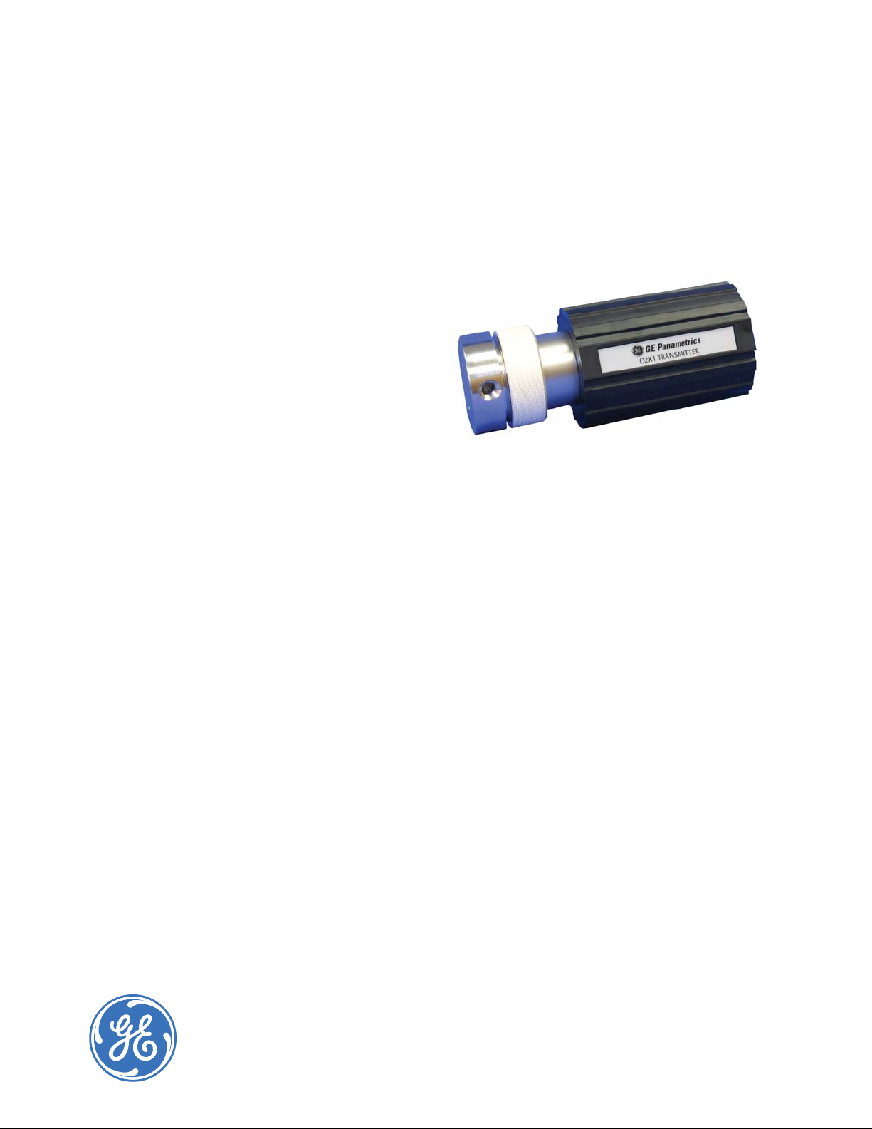
O2X1
Panametrics Oxygen
Transmitter
Applications
An oxygen transmitter for use in:
• Heat treating and bright annealing
• Process monitoring of gaseous monomers
• Pure gaseous hydrocarbon streams
• Inert welding gases
• Glove box leak detection
• Ambient air monitor
Features
• Intrinsically safe
• Two-wire, loop-powered 4 to 20 mA transmitter
• Proven galvanic fuel cell O
• Programmable ranges for ppm and percent
oxygen
• Microprocessor-based, all-digital technology for
reliable operation
• Continuous monitoring
• Low maintenance
• Economical and compact
sensor technology
2
Page 2

Panametrics Oxygen Transmitter
Control at the Tip of a Finger
The O2X1 is a highly reliable and cost-eff ective two-wire,
loop-powered transmitter with a linearized 4 to 20 mA
output. It measures oxygen in four ppm ranges (10; 100;
1,000 and 10,000 ppm) and three percentage ranges (1,
10, and 25%). All ranges are user-programmable. This
compact transmitter uses proven sensor technology
to accurately measure O2 in a variety of gases, even in
hazardous environments.
Proven Sensor Technology
The O2X1’s oxygen sensor is an advanced galvanic
fuel cell that provides superior performance, accuracy,
stability and long life. The cell’s innovative design
eliminates the potential for negative signal output,
reduces sources of contamination and eliminates
electrolyte leakage.
The cell is unaff ected by other background gases or
hydrocarbons and is compatible with acid gases (OX-2
and OX-4 cells). Recovery from air at low ppm levels takes
just a few minutes. Because the cell is self-contained,
little maintenance is required. There is no electrolyte to
change or electrodes to clean.
The rugged O2X1 is controlled by a microprocessor that
enables the user to select the range, trim outputs and
perform calibration. Programming is easily done using the
three-button keypad and the three light-emitting diodes
(LEDs). These switches allow complete functionality in
hazardous areas when equipped with an MTL706 barrier.
Installation Flexibility
The compact O2X1, with its built-in microprocessor, is
designed to fi t easily into any installation site. The O2X1
can be installed right at the sampling point, whereas
other transmitters must be rack or panel mounted.
Sample Systems
In addition to standard features and options, GE off ers
a full line of sample handling systems for a variety
of applications. If needed, GE can design and build a
sample conditioning system to meet unique application
requirements. Please contact GE for details.
Oxygen Sensor Interference Gases
Intrinsically Safe
When equipped with the optional MTL706 barriers, the
O2X1 can be mounted in a hazardous (classifi ed) location
as defi ned by the National Electrical Code (NEC). The
O2X1 316 stainless steel package is FM approved as
intrinsically safe for use in Class I, II, III; Division 1; Groups
A,B,C,D,E, F&G hazardous (indoor/outdoor) Type 4X
locations, and is certifi ed by BASEEFA II 1 G EEx ia IIC T4
(Tamb = –20°C to +60°C)
Gas OX-1 and OX-5,
ppm Cont.
H2S <5 ppm <10 ppm 0.0005% 0.01% 0.001% 0.1%
<10 ppm <10 ppm 0.01% 0.1% 0.01% 0.1%
SO
3
<10 ppm (3) 0.01% 0.1% (3) (3)
SO
2
HCI <1000 ppm (3) 0.1% 1.0% (3) (3)
HCN <1000 ppm (3) 0.1% 1.0% (3) (3)
<1000 ppm (3) 0.1% 20% (3) (3)
CO
2
(2) (2) (2) (2) (2) (2)
NO
2
(2) (2) (2) (2) (2) (2)
CL
2
Cont. = Continuous, Int. = Intermittent
(1) Recommended maximum exposure 30 minutes followed by fl ushing with
ambient air for equal period
(2) Minimal eff ect on sensor performance, but produces signal interference of
1:2 ratio
(3) Minimal eff ect on sensor performance
OX-2, ppm
Cont.
OX-3, %
Cont. Int . (1)
OX-4%
Cont. Int .
Page 3

O2X1
Specifi cations
Intrinsically Safe (IS) Installation
Intrinsically safe installations require an MTL706 zener
barrier, one IS cable and one non-IS cable.
Power Requirements
24 to 28 VDC at 50 mA
Field Programmable
Measurement Ranges
• Ppm sensors:
– 0 to 10 ppmv O2 (OX-1 or OX-2 in 316 stainless steel
package only)
– 0 to 100 ppmv O
– 0 to 1000 ppmv O
– 0 to 10,000 ppmv O
• Percent sensors:
– 0% to 1% O
– 0% to 10% O
– 0% to 25% O
2
2
2
2
2
2
Cable
• OCI-*F-T5 in hazardous area: Two-conductor, twisted
pair with connector; 22 AWG; 1100 ft (335 m) maximum
cable length
• OCG-*F-0 in non-hazardous (safe) area:
Three-conductor; 22 AWG; 4000 ft (1219 m) maximum
cable length
Output
Total load must equal 250 Ω ±5%
Non-Hazardous (Safe) Installation
No zener barrier is used.
Process Wetted Materials
• SS process unit: 316 stainless steel, Viton® O-ring and
polytetrafl uoroethylene
• Delrin® process unit: Delrin, Viton O-ring and
polytetrafl uoroethylene
• Ambient air monitoring unit: Delrin, Viton O-ring and
polytetrafl uoroethylene
Power Requirements
9 to 28 VDC loop powered, 0.6 W max
Cable
OCG-*F-T5: 2 conductor, twisted pair with connector;
22 AWG; 0.04 Ω/ft; 4000 ft (1219 m) maximum cable
length
Output
Max. load (Ω) = [40 Ω x (PSV – 8)] – RC where:
PSV = power supply voltage in VDC, and
RC = cable resistance (22 AWG cable has 0.04 Ω/ft)
Example:
Given a 24 VDC power supply and a 1000 ft (305 m)
cable (22 AWG, 0.04 Ω/ft),
RC = 1000 ft x 0.04 Ω/ft = 40 Ω
Max. load = [40 x (24 – 8)] – 40
= [40 x 16] – 40
= 600 Ω
Accuracy
• ±1% of span at calibration point
• ±2% of span at the calibration point for the 0 to 10
ppmv range (OX-1 or OX-2 in 316 stainless steel
package only)
Repeatability
• ±1% of span
• ±2% of span for the 0 to 10 ppmv range (OX-1 or OX-2
in 316 stainless steel package only)
Resolution
±0.1% of span
Linearity
±2% of span
Operating Temperature
32°F to 113°F (0°C to 45°C)
Ambient Temperature Eff ect
±3% of reading over operating temperature range
Sample Pressure
Vented to atmosphere during operation and calibration
Atmospheric Pressure Eff ect
±0.13% of reading per mmHg (directly proportional to
absolute pressure). During calibration, pressure and fl ow
must be kept constant.
Process Connection
• 316 stainless steel and Delrin process units: 1/8 in NPT
inlet and outlet
• Ambient air monitoring unit: None
Page 4

Sample Flow Rate
1.0 SCFH (500 cc/min) recommended for process units
Electrical Classifi cation/Certifi cation
• Weatherproof, 316 stainless steel and Delrin process
packages only: Type 4X/IP66
• Intrinsically safe, 316 stainless steel package only: Class
I, II, III; Division 1; Group A,B,C,D,E,F&G;
FM/CSA
II 1 G EEx ia IIC T4
(Tamb = –20°C to +60°C);
BAS01ATEX1094X
316 stainless steel ATEX compliance with EN50104 from
32°F to 104°F (0°C to 40°C)
Order and Calibration Information
Record selected option in blank indicated at bottom of form.
O2X1 Oxygen Transmitter
Sensor
0 None
1 Standard ppm, 0 to 10 ppm
2 Acid ppm, 0 to 10, 100 and 1000 ppm
3 Standard %
4 Acid %
5 Standard ppm, 0 to 100 and 1000 ppm
Package
0 316 stainless steel process FM/CSA
1 Delrin process
2 Delrin ambient air monitoring
3 316 stainless steel process ATEX
9 316 stainless steel general purpose
European Compliance
Complies with EMC Directive 89/336/EEC
Hazardous Location Non-Hazardous (Safe) Location
O2X1 Transmitter
*Specify cable length in ft(m)
1. Equipment connected to barrier inputs must not use or
generate more than 250V.
2. Total load of R1 + R2 must equal 250Ω ±5%.
OCB-*F-T5
IS cable
O2X1 – __ __ Use this number to order product
OX Spare Oxygen Sensor
Sensor
1 Standard ppm, 0 to 10 ppm
2 Acid ppm, 0 to 10, 100 and 1000 ppm
3 Standard %
4 Acid %
5 Standard ppm, 0 to 100 and 1000 ppm
OX – __ Use this number to order product
ZBB
Black
Red
3
4
MTL706
barrier
bus bar
IS
ground
OCB-*F-0
non-IS cable
Red
1
2
Green
Black
Green
Power supply
24V
24V return
- R1 +
R2
Power supply
O2X1 Transmitter
Red
Black
OCB-*F-T5
non-IS cable
*Specify cable length in ft(m)
Maximum load of analog input device is dependent on
power supply voltage and cable resistance.
O2X1 intrinsically safe installation (top) and non-hazardous (safe) installation (bottom).
24V
24V return
4 to 20 mA
analog input
device
www.gesensinginspection.com
920-040D
© 2009 General Electric Company. All Rights Reserved. Specifi cations are subject to change without notice. GE is a registered trademark of General Electric Company. Other company or product
names mentioned in this document may be trademarks or registered trademarks of their respective companies, which are not affi liated with GE.
 Loading...