

Page 1
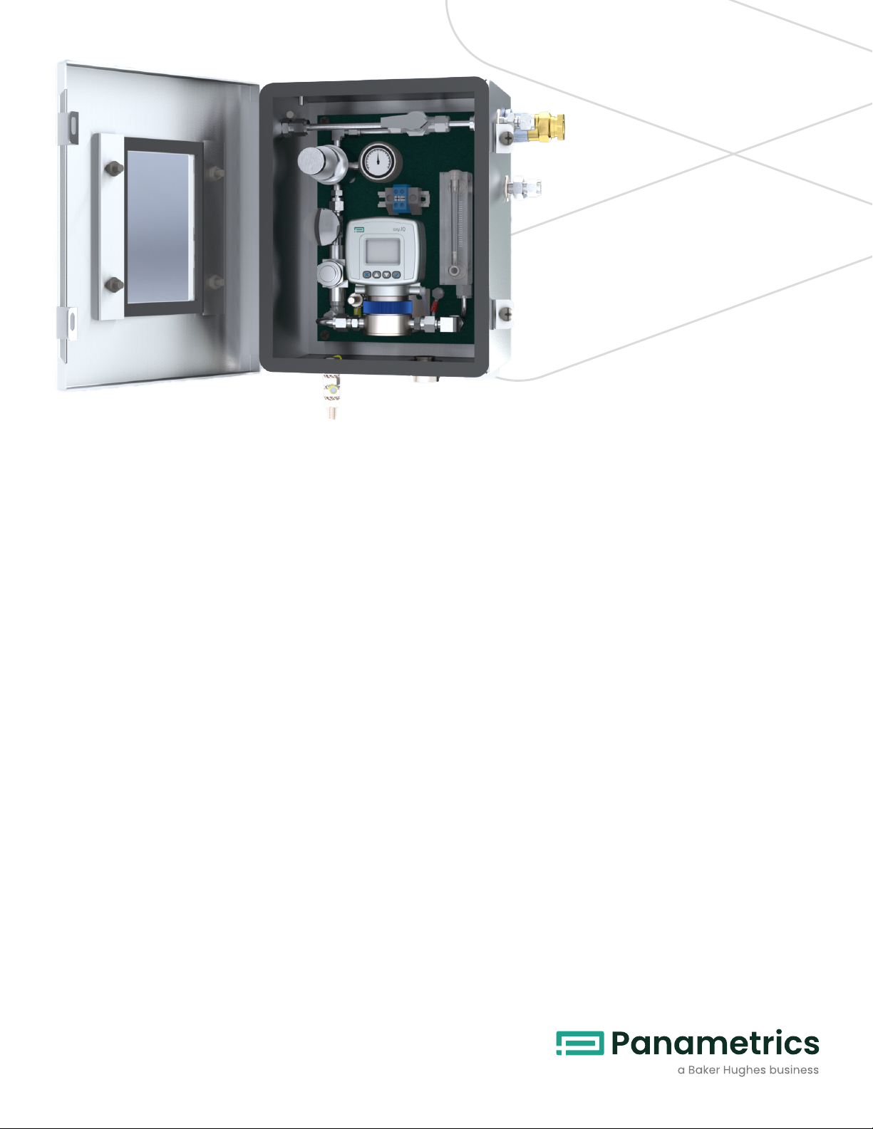
O2.IQ oxygen analyzer
packaged solution
Features
O2.IQ simplifies and standardizes your options for reliable
oxygen measurement in a variety of applications. At the
heart of this package is the oxy.IQ analyzer supported
by a sample conditioning system purposefully designed
to maintain ease of access and functionality in a space
conscious housing. Simply mount the O2.IQ, connect to
the two terminals and the analyzer is ready for its field
calibration. Key highlights include:
• Wall mounted NEMA 4X and IP66 stainless steel package
• Features the oxy.IQ electrochemical analyzer
• Package designed with ease of access including
accessibility to sensor cell replacement
• Sample conditioning system provides isolation, filtration,
pressure regulation, flow and pressure indication along
with a clear window for easy viewing of all readings
Applications
The standard O2.IQ package has been designed with
oxygen measurement in natural gas pipelines in mind;
however, the package is easily transferrable to a wide range
of applications, given its standard sampling conditioning
system. The pressure regulation functionality allows for
inlet pressures of up to 400 psig (27.5 bar) and reduces to
ambient pressure for accurate measurement.
The compact footprint of this stainless-steel package
combined with the loop powered oxy.IQ analyzer make it
perfect for safe and hazardous area locations. Markets and
applications served include:
• Industrial gas production
• Natural gas
• Petrochemical
• Heat treating and annealing
• Inert weld gases
• Gaseous hydrocarbon streams
Page 2
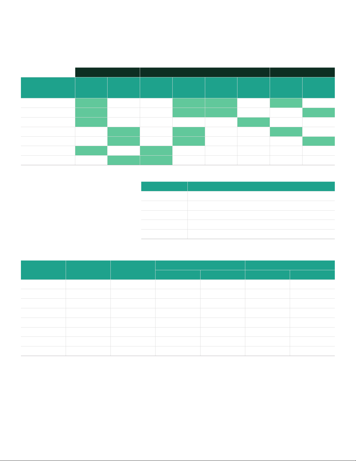
Ordering configuration
The O2.IQ is available in 7 different off-the-shelf configurations covering general purpose to hazardous area requirements,
barrier types and metric or imperial fittings. The selection grid highlights the ordering part number which corresponds to the
features required for your application and relevant area classification.
Fitting selection Area classification Barrier type
Class 1
Div 2 Non
incendive
Zener
barrier
Galvanic
isolator
Ordering Part No. Imperial Metric
O2.IQ-CL1-DIV1-Z
O2.IQ-CL1-DIV1-G
O2.IQ-CL1-DIV2
O2.IQ-IS-Z
O2.IQ-IS-G
O2.IQ-GP-I
O2.IQ-GP-M
✔ ✔ ✔ ✔
✔ ✔ ✔ ✔
✔ ✔
✔ ✔ ✔
✔ ✔ ✔
✔ ✔
✔ ✔
General
purpose
Intrinsically
safe global
Class 1 Div 1
The O2.IQ also requires selection of the
appropriate electrochemical OX sensor
for the oxy.IQ. Ordering configurations
for the OX sensors are as follows and
please refer to the sensor interference
gases for further information.
OX-1 Low range ppm measurement, standard background gases
OX-2 Low range ppm measurement, acid background gases
OX-3 Percent measurement, standard background gases
OX-4 Percent measurement, acid background gases
OX-5 Low/mid-range ppm measurement, standard background gases
Oxygen sensor interference gases
Ordering Part No. Summary
Gas OX-1 and OX-5 OX-2
Continuous Intermittent (1) Continuous Intermittent (1)
H2S <5 ppm <10 ppm 0.0005% 0.01% 0.001% 0.1%
SO
SO
3
2
<10 ppm <10 ppm 0.01% 0.1% 0.01% 0.1%
<10 ppm (3) 0.01% 0.1% (3) (3)
HCl <1000 ppm (3) 0.1% 1.0% (3) (3)
HCN <1000 ppm (3) 0.1% 1.0% (3) (3)
CO
2
NO
2
Cl
2
(1) Recommended maximum exposure 30 minutes, followed by flushing with ambient air for an equal period.
(2) Minimal effect ons ensor performance, but produces signal interference of 1:2 ratio for ppm levels only (e.g., 100 ppm NO2 looks like 200 ppm O2).
(3) Minimal effect on sensor performance.
<1000 ppm (3) 0.1% 20 & (3) (3)
(2) (2) (2) (2) (2) (2)
(2) (2) (2) (2) (2) (2)
OX-3 OX-4
Application parameters
• Sample Gas pressure: 0 - 400 psig (0 - 27.5 Bar)
• Sample gas temperature: 32 to 113°F (0 to 45°C)
• Power requirements: 24 to 28 VDC at 50 mA
Page 3

oxy.IQ specifications
All installations
Accuracy
• ±1% of range at calibration point
• ±2% of range at the calibration point for the 0 to 10 ppmv
range (OX-1 or OX-2 only)
Repeatability
• ±1% of range
• ±2% of range for the 0 to 10 ppmv range (OX-1, OX-2 only)
Resolution
• ±0.1% of range
Linearity
• ±2% of range (OX-1, 2, 3, 5)
• ±5% of range (OX-4)
O2 Sensor operating temperature
32 to 113ºF (0 to 45ºC)
Sample pressure
Vented to atmosphere during operation and calibration
Atmospheric pressure effect
±0.13% of reading per mmHg (directly proportional to
absolute pressure). During calibration, pressure and flow
must be kept constant.
Process connection
1/8 in. NPT inlet and outlet
Dimensions
4.10 x 2.75 x 2.05 in (104.1 x 69.9 x 52.1 mm)
Weight
1.35 lb (612 grams)
Sample flow rate
1.0 SCFH (500 cc/min) recommended for process units
Electrical classification certification
Intrinsically safe
USA/Canada
IS for Class 1, Groups ABCD, T4
AEx ia IIC T4
ATEX and IECEx
Ex ia IIC Ga T4 Tamb -20 to 60ºC
IS package, non-incendive without use of Zener barrier or
galvanic isolator:
• USA/Canada: Class 1, Div 2, Groups A, B, C, D: T4
European compliance
Complies with EMC directive 2004/108/EC
User-selectable measurement range
and corresponding sensor
Oxygen Content
0 to 10 ppmv
0 to 20 ppmv
0 to 50 ppmv
0 to 100 ppmv
0 to 200 ppmv
0 to 500 ppmv
0 to 1,000 ppmv
0 to 2,000 ppmv
0 to 5,000 ppmv
0 to 10,000 ppmv
OX-1 and
OX-2
✔
✔
✔
✔ ✔
✔ ✔
✔ ✔
✔ ✔
✔ ✔
✔ ✔
✔ ✔
OX-3 and
OX-4
0% to 1%
0% to 2%
0% to 5%
0% to 10%
0% to 25%
0% to 50%
OX-5
✔
✔
✔
✔
✔
✔
Page 4

Installation options
Class 1 Div 1/Zone 0 | Global Intrinsically Safe
Hazardous Location Non-Hazardous Location
(1)
ZBB BUS BAR
BROWN
3
4 2
BLUE
MTL7706
1
GREEN
RED
GREEN
BLACK
POWER SUPPLY
+24V
24V RETURN
Class 1 Div 2 - Non incendive
IS Cable
(Blue Jacket)
(1)
1. Equipment connected to barrier
inputs must not use or generate
more than 250V.
2. Total load of R1 + R2 must equal
250 ohms ±5%.
IS GROUND
Non-IS Cable
Hazardous Location Non-Hazardous Location
(1)
BLUE
BROWN
Black Jacket
(1)
Maximum load of analog input device is
dependent on power supply voltage
and cable resistance.
BROWN
4-20MA ANALOG
INPUT DEVICE
R1
BLACK
R2
POWER SUPPLY
+24V
24V RETURN
4-20MA ANALOG
INPUT DEVICE
Non-Hazardous Location POWER SUPPLY
General Purpose
Note: Wiring to integrated terminal strip to be completed at installation site. oxy.IQ connection cable ships separately
(1)
Terminal strip and oxy.IQ connector are internal of the O2.IQ housing. Shown externally for illustration purposes only
(1)
Black Jacket
(1)
BLUE
BROWN
Maximum load of analog input device is
dependent on power supply voltage
and cable resistance.
BROWN
+24V
24V RETURN
4-20MA ANALOG
INPUT DEVICE
Page 5

Start up procedure
Initial setup
• Ensure external wiring is securely connected to the terminal
strip provided in the O2.IQ and that the oxy.IQ cable is
securely fastened at the back of the transmitter and wired
into the terminal blocks provided. Pay special attention to
barrier installation and wiring if in hazardous area. (See
oxy.IQ manual Section 2.2)
• Referring to section 2.3 of the oxy.IQ user manual install the
electrochemical cell into the oxy.IQ
• Follow the procedure set out in Sections 3.3.1 – 3.3.3 to set
up and perform initial air calibration of the unit
• On completion of initial setup, insert the oxy.IQ into its
manifold and ensure it is securely mounted in the O2.IQ
sample handling system
Span calibration
• Check that the needle valve (4) is fully closed and that
the pressure regulator(2) is backed out by rotating anticlockwise
• Slowly open the needle valve to allow any trapped
pressure and gas to vent to the outlet in the event the unit
was in use previously and was shut down for an extended
period
• Switch the 3-way selection valve (1) to point in the direction
of calibration inlet and attach the calibration gas to the
calibration gas inlet port
• Allow calibration gas to flow into the O2.IQ and slowly
turn the pressure regulator clockwise until the pressure
gauge (3) reads 1-2 psig. Crack open the needle valve and
monitor the flow rate on the rotameter (7) and pressure on
the pressure gauge
• Slowly adjust the needle valve until a steady flow rate of 1.0
SCFH (500cc/min) is reached
• Adjust until a steady flow rate of 1.0 SCFH (500cc/min) and
a pressure of 0 psig (14.7 psia) is achieved
• Carry out span calibration as per Section 3.3.4 of the oxy.IQ
manual
• When calibration is complete, switch the 3-way selection
valve to the central block position and fully close in the
needle valve while backing out the pressure regulator by
turning anti-clockwise
Bringing process gas online
• Check that the needle valve is in the closed position and
switch the 3-way selection valve to point in the direction of
the process inlet connection
• With the process gas flowing to the system, slowly turn
the pressure regulator clockwise until the pressure gauge
reads 1-2 psig. Open the needle valve and monitor the flow
rate on the rotameter and pressure on the pressure gauge
• Slowly adjust the needle valve until the flow rate is steady
at 1.0 SCFH (500cc/min)
Shut down procedure
• Slowly shut the needle valve until the flow rate on the
rotameter reads zero flow
• Switch the 3-way selection valve to the block position,
isolating the process gas
• Re-open the needle valve to allow any trapped process
pressure to vent to the outlet
• Close the needle valve back in as added protection
against process gas pass through during shut down or
maintenance periods
Page 6

Figure 2 - O2.IQ Diagram
Page 7

Notes
1. The O2.IQ will ship with a standard oxy.IQ cable in separate
packaging. This offers the end user the capability of wiring
directly to their associated equipment if the terminal
strip is not required. All wiring should be carried out in
accordance with the wiring schematic shown and for
the appropriate area classification. Responsibility for the
quality of workmanship will be with the end user.
2. The O2.IQ is a robust package with many potential
applications. As with all analyzers however, it has certain
limitations beyond which could impact on the relibaility of
measurement and safety. If any question remains around
the suitability of the O2.IQ for a particular application then
Panametrics are happy to assist with our specialist team
of application engineers to support customers in their
selection process.
3. While the O2.IQ is a packaged solution which is ordered
under a single part number, the electrochemical oxygen
sensor must be ordered separately. The selection of
the OX sensor which is most suitable for the application
should be done in accordance with the selection table
included in this datasheet and/or in consultation with
Panametrics sales support. The electrochemical sensors
which are determined by the OX preface will be shipped
as dangerous goods which is standard procedure for all
electrochemical sensors.
Page 8

Copyright 2020 Baker Hughes Company. All rights reserved.
BHCS34789 (06/2020)
panametrics.com
 Loading...