

Page 1

Trace moisture Transmitter for
pressure or atmospheric dewpoint
®
DewPro
MMY30
Installation and Operation Manual
GE Measurement & Sensing Technologies
GE General Eastern
Page 2

DewPro MMY30
Caution!
Safety
General Notes
Caution!
Before installation please read all instructions.
Safety
- The DewPro is designed to be mounted to pressurized systems. Take necessary
precautions when mounting or removing the DewPro.
General Eastern reserves the right to change or modify our product appearance and
specifications at any time and without notice. Therefore, information in this document is
subject to change without notice and does not represent a commitment on the part of
General Eastern.
No part of this manual may be reproduced or transmitted in any form or by any
means, electronic or mechanical, including photocopying and recording, for any
purpose without the express written permission of General Eastern.
DewPro is a Registered Trademark of General Eastern.
If you should have questions regarding the product described in this document, or need
further assistance, please contact your local GE General Eastern Sales Centre
Installation and Operation Manual
GE General Eastern
2
Page 3

DewPro MMY30
Installation and Operation Manual
Contents
General Notes 2
1.0 General System Information …………………………. 5
1.1 Unpacking and Inspection 5
1.2 Introduction 6
1.3 Theory of Operation 6
1.4 Dimensions 7
2.0 Installation Guidelines …………………..……………. 7
2.1 General Hints 7
2.2 Method 1 - Orifice at Outlet 8
2.3 Method 11 - Orifice at Inlet 9
2.4 Method Ill - No Flow Restriction 9
2.5 Method IV - Bypass Installation 10
3.0 Wiring Instructions …………………………………... 11
3.1 Wiring, General Guidelines 11
3.2 System Configuration 11
3.3 Mounting in Normal Environments 12
3.4 Mounting in Environments with Severe Electrical Noise 12
3.5 Electrical Connection 12
3 6 General Wiring Instructions 13
4.0 Optional Display/User Interface……………………… 14
4.1 Installation 14
4.2 Description of the DewPro MMY 30 Programming Matrix 15
4.3 Special Functions of the Pushbuttons 16
4.4 Functions of the Matrix (Refer to Figure 20 or appendix) 16
GE General Eastern
3
Page 4

DewPro MMY30
Installation and Operation Manual
5.0 Troubleshooting 21
5.1 General Recommendations 21
5.2 Removing the Filter 21
6.0 Technical Specifications 23
6.1 Optional Onboard Display with User Interface 23
7.0 Accessories 24
7.1 Available Accessories 24
7.2 Example of Power Supplies and Displays23 24
Appendix
GE General Eastern
4
Page 5
DewPro MMY30
Installation and Operation Manual
1.0 General System Information
1. 1 Unpacking and Inspection
Upon receipt of the DewPro MMY 30, examine the shipping carton for broken or
open packing, distortion, or any other evidence of mishandling. If inspection
indicates damage to the unit or any of its components, notify the carrier (within 15
days of delivery) and request an inspection.
Move the carton to a clean work area and unpack. The carton you receive should
contain:
• DewPro MMY 30
• Installation and Operation Manual
• Calibration Certificate
Compare the model number (on the product label) with product structure (see
below) to ensure you have received everything you ordered.
GENERAL EASTERN
MODEL:
SERIAL NO:
SUPPLY:
RANGE:
P max: 500 PSIG
Product Structure
MMY30 -
Certification/Approvals:
R Standard (not certified)
Other
Y
Process Connection:
2
1 ½” MNPT (1/4” tube fitting if B, C or D is selected below)
G ½ (6 mm tube fitting if B, C or D is selected below)
9 Other
Orifice Configuration:
A
D
Inlet: None; Outlet: Orifice, with ¼” FNPT
B Inlet: None; Outlet: Orifice, with (6 mm) ¼ " tube fitting
C Inlet: None; Outlet: None, with (6 mm) ¼ " tube fitting
Inlet: Orifice; Outlet: None, with (6 mm) ¼ " tube fitting
Y Other
Enclosure Conduit:
1
½ " FNPT
2 PG 16
9 Other
Output Configuration/Dewpoint Range:
A Td -90 oC to +10 oC (-130 oF to +50 oF), no display, error
22 mA
B
Td -90 oC to +10 oC (-130 oF to +50 oF), no display, error
Hold
C Td -90 oC to +10 oC (- 130 oF to +50 oF), no display,
error 3.6 mA
F
D 0-100 ppmv 1 bar, no display, error 22 mA
E 0-100 ppmv 1 bar, no display, error Hold
0-100 ppmv 1 bar, no display, error 3.6 mA
G With integral display/user interface
Y Other
R 2 A 2 A
The Humidity Experts
MMY30-R-2-A-2-A
10124
9...32 VDC
Unpacking
Check Model
Number
Fig. 1
GE General Eastern
5
Page 6
DewPro MMY30
Installation and Operation Manual
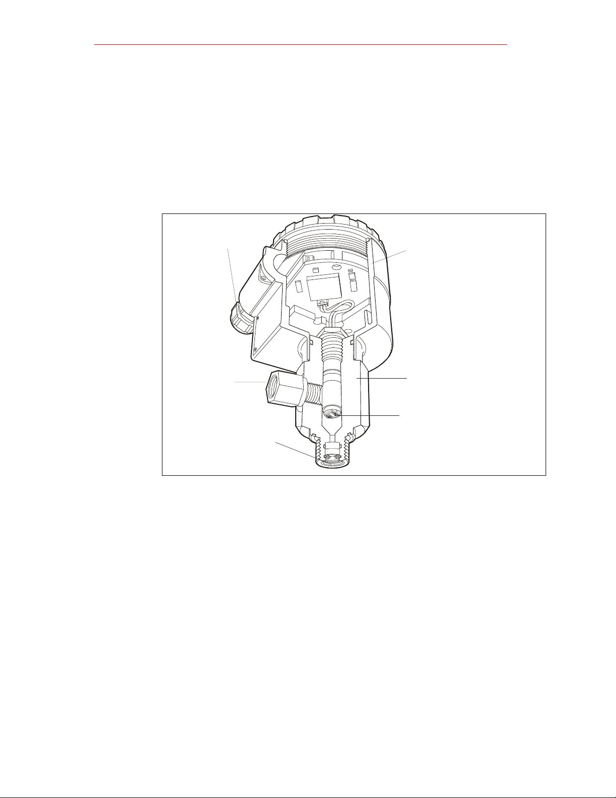
1.2 Introduction
Unit description
The DewPro MMY 30 trace moisture transmitter is a loop-powered dewpoint
measuring device. The transmitter includes a sensor element, a flow chamber, a
weather-proof enclosure, microprocessor electronics, and assorted fittings all in a
compact assembly In most cases, either the inlet or outlet port includes an orifice to
regulate the flow. The placement of this orifice determines whether the dewpoint
measurement is done at process (line) pressure (outlet orifice), or at atmospheric
pressure (inlet orifice). A 2 micron sintered inlet filter prevents particles from entering
the device.
Optional
Display/User
The optional display/user interface feature allows the DewPro to be configured to the
user's specifications. See Chapter 4.0, pages 14-20 for more information.
Interface
Power Signal
Cable Entry
Electronics Housing
Outlet
(Exhaust)
Fitting
Flow Cell
SensorElement
Fig. 2
Sinterfilter
Inlet (Process
Connection)
1.3 Theory of Operation
4 to 20 mA
Loop
By-pass In dryer applications, the moisture sensor performs best when mounted in a bypass. The
Planar Sensor
Calibration Each DewPro is factory calibrated against precise NIST certified moisture references
The DewPro MMY 30 microprocessor controlled electronics operate with a DC voltage
supply from 12 to 32 V DC. At the nominal 24 V DC supply, the maximum loop resistance
is 600 Ohm. The signal is represented by the 4 to 20 mA loop current and is
directly proportional to the dewpoint range in oC or oF In the standard range, 4 mA
corresponds to -90 oC (-130 oF) and 20 mA to +10 oC (+50 oF) dewpoint temperature.
The optional unit of measure is ppmv in the standard range 0 - 100 ppm-v.
built-in bypass of the DewPro eliminates costly hardware associated with traditional
sampling methods. The DewPro installs simply into the process with its G ½ or ½ "
MNPT threaded connection.
The heart of the MMY 30 is the new planar sensor element. It incorporates a new,
superior aluminum oxide sensor that provides longer calibration stability, excellent
corrosion resistance, and improved speed of response. The sensor, mounted on a
ceramic substrate, also has a reduced temperature coefficient.
and has an accuracy of ñ2 OC dewpoint. For field recalibration, GE General Eastern is
offering a unique calibration device. The MMY145 field calibrator connects to the DewPro
on site and corrects the calibration data automatically.
GE General Eastern
6
Page 7
DewPro MMY30
Installation and Operation Manual
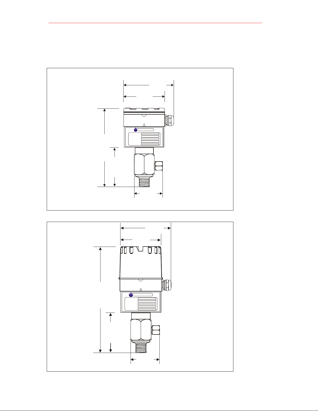
1.4 Dimensions
Choose a mounting location which allows enough clearance for the use of tools and
for connection of the field calibrator.
116
86
GENE RAL EAS TERN
The Humidity Experts
MMY30
MODEL:
SERIAL NO:
12...32 VDC
SUPPLY:
DEWPOINT RANGE:
P max:
168
83
PSIG
65
1 mm = 0,04 in
.
Standard DewPro
Fig. 3
116
76
220
MODEL:
SERIAL NO:
SUPPLY:
DEWPOINT RANGE:
P max:
GENERAL EASTERN
The Humidit y Expe rts
MMY30
12...32 VD C
PSIG
83
65
1 mm = 0,04 in
.
DewPro with
Optional
Display/User
Interface
Fig. 4
GE General Eastern
7
Page 8
DewPro MMY30
2.0 Installation Guidelines
2.1 General Hints
• Mount the DewPro vertically whenever possible to prevent particles or
condensation from entering the bypass.
• Mount the DewPro after a shut-off valve to depressurize the DewPro when
removing it from the process pipe in case of maintenance or field calibration.
Caution!
Do Not OverTighten
Caution!
The outlet fitting is connected to the bypass block with a G 114 straight thread
(with gasket) which will seal if the fitting is simply hand-tightened. When
connecting an external device, counter the fitting with a second wrench when
tightening.
If the inlet is equipped with a G 112 straight thread and gasket, the seal is obtained
by simply hand-tightening the DewPro.
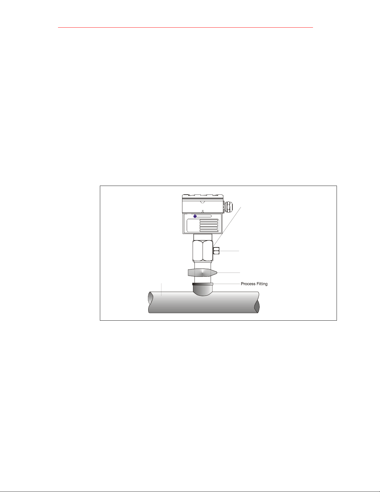
2.2 Method I – Orifice at Outlet
Fig. 5
Pressure
Dewpoint
Air Flow
Air dryers producing general instrument air are typically specified with a pressure
dewpoint rating. The majority of dryers operate in a dewpoint range between -40 oC to
-75 oC (-40 oF to -100 oF). A pressure of 7 to 8 bar (= 100 psig) is very common.
The DewPro is designed to measure the pressure dewpoint. By restricting the flow at
the outlet of the integral bypass with an orifice, the sensor monitors the dewpoint at
process pressure. The bleed-off air to the atmosphere at 7 to 8 bar (100 psig),is
approximately 70 cc/min. (=4 [/h or =0. 14 cfh). For smaller sized dryers of 3m'/min.
(=100 cfm) the air loss is only 0.002% of the air production and is negligible.
Despite the very low flow rate through the bypass as shown, the air sample in the
DewPro bypass chamber is refreshed every second due to the small volume design.
As a result, the sensor sees changes in moisture instantaneously.
Due to the low flow rate, the flow velocity is also very low at < 0.01 m/sec. (=34m/h).
The low flow velocity prevents the inlet filter from clogging since there is not enough
kinetic energy to draw dust particles into the filter.
Process Pipe
GENERAL EASTERN
MODEL: MMY30
SERIAL NO:
SUPPLY:
DEWPOINT R ANGE:
P max:
Installation and Operation Manual
G ¼" Straight Thread
The Humidity Experts
12...32 VDC
PSIG
Outlet connection with orifice
Shut-off valve
GE General Eastern
8
Page 9

DewPro MMY30
Installation and Operation Manual
2.3 Method II – Orifice at Inlet
G ¼" Straight Thread
GENERAL EAS TERN
MODEL:
SERIAL NO:
SUPPLY:
DEWPOINT RANGE:
P max:
MMY30
9...32 VDC
PSIG
The Humidity Expe rts
6 mm compression fitting
Diffusion Coil
Shut-Off valve
2.4 Method III – No flow restriction
GENERAL EASTERN
MODEL:
SERIAL NO:
SUPPLY:
DEWPOINT RANGE:
P max:
MMY30
12...32 VDC
PSIG
The Humidity Experts
G ¼ " Straight Tread
6 mm compression fitting
Pressure drop
Closed loop drying systems, which are very common with hopper dryers in the Low
Pressure Closed Loop plastics industry, operate at very low pressures of a few
inches of water. The air passing through the DewPro bypass is fed back to the main
stream after a pressure drop in the main line.
In this configuration, the DewPro bypass has no flow restriction at the inlet and
outlet.
The outlet is equipped with a 6 mm (l/4") tube fitting to allow simple connection of
the loop tubing.
Fig. 6
Low pressure
closed loop
Fig. 7
GE General Eastern
9
Page 10

DewPro MMY30
Installation and Operation Manual
Method IV – Bypass Installation
Fig. 8
Remote
installation
Fig. 9
Wall Mounting
G ¼ " Straight Tread
GENERAL EASTERN
The Hu mi dity E xpe r ts
MMY30
MODEL:
SERIAL NO:
SUPPLY:
DEWPOINT RANGE:
P max:
12...32 VDC
PSIG
6 mm compression fi tting
6 mm (1/4") Tubing from
Process
In some cases there may not be enough room to install the DewPro directly to the
process pipe. The tube connection at the inlet allows mounting the DewPro at a remote
location. The functions of Methods 1-III can be selected.
G ¼" Straight Thread
GENERAL EASTERN
The Humidity Experts
MODEL: MMY30
SERIAL NO:
SUPPLY:
12...32 VDC
DEWPOINT RA NGE:
P max:
PSIG
Mounting
bracket
The DewPro can be mounted on a wall or a plate using a bracket available from GE
General Eastern.
6 mm tubbing fitting
6 mm (1/4") Tubing from
Process
GE General Eastern
10
Page 11

DewPro MMY30
2
Installation and Operation Manual
3.0 Wiring Instructions
3.1 Wiring, General Guidelines
Note: If the DewPro is equipped with an optional display/user interface, please refer
to section 4.0, page 14 prior to wiring
Caution!
The DewPro system contains electronic components that are susceptible to damage
by electric electricity. Proper handling procedures must be observed during the
removal, installation, or other handling of internal boards or devices.
3.2 System Configuration
8888
GENERAL EASTERN
The Humid i ty Expe r ts
Note regarding customer's power supply: The voltage at the +/- terminal of the
Designing the Loop DewPro should not fall below 12 V DC. The maximum loop resistance
is an important measure for selection of the supply voltage. Each device connected to the
loop causes a voltage drop. For instance, using a loop-powered display with an input
impedance of 50 fl will cause a voltage drop of 1 V DC at 20 mA using Ohm's law.
Connecting the loop to a PLC will cause a voltage drop across the input.
When designing your loop, add up all voltage losses across the devices connected to the
loop and add 12 V The sum will be the minimum supply voltage required from the power
supply Calculate with a 20% safety factor.
Optional loop powered
display available from
General Eastern, such as Md102
Customer s power supply
24 V DC ( 9...32 V DC )
-
Power suppl y
available from General Eastern
~
8888
-
Power supply with display
and optional relay availabl e
from General Eastern such as Md10
~
115 /2 30 V
AC
115/230 V
AC
Caution!
Various Power
Supplies /
Displays
Fig.10
Designing the
Loop
GE General Eastern
11
Page 12

DewPro MMY30
3.3 Mounting in Normal Environments
Standard
Fig.11
• A standard four-wire, stranded cable can be used to interconnect the DewPro
with the power source.
Two -W ire
Cable
External
Earth
Ground
3.4 Mounting in Environments with Severe Electrical Noise
EMI/RFI
Fig.12
• In areas where EMI/RFI interference is likely a shielded signal cable is to be used
for full protection. The DewPro MMR31 meets requirements of IEC 801-1
through 6 (EN 50081-1, 50082-2) when shielded cable is used.
Shielded Two-Wire
Cable
Fasten Shield under Cable
Clamp for Maximum
RFI Protection
3.5 Electrical Connection
Fig. 13
G
E
N
E
R
A
L
E
T
h
A
e
H
S
u
m
T
i
d
i
E
t
y
E
R
x
p
e
N
r
t
s
External
Earth Ground
Installation and Operation Manual
Capped
Off
Capped
Off
+
24 V DC Nominal (9-32V)
-
+
24 V DC Nominal (9-32V)
-
GE General Eastern
12
Page 13

DewPro MMY30
Installation and Operation Manual
3.5 General Instructions
1. Unscrew the cap on top of the unit.
2. Loosen the grey cable gland located on the side of the unit
3. Feed the cable through the conduit opening.
Use a standard signal cable size.
NOTE:
4. Retighten the grey cable gland to meet IP 67 and to relieve any stress on the
wire.
5. Verify that 12 to 32 V DC is across the terminals marked + and -.
NOTE: This is the voltage that appears across the DewPro terminals,
not necessarily the power supply voltage due to voltage loss in wire length, displays,
indicators, etc.
6. Connect shield to internal grounding for maximum EMI / RFI protection
GE General Eastern
13
Page 14

DewPro MMY30
Installation and Operation Manual
4.0 Optional Display/User Interface
4.1 Installation
If the DewPro is equipped with an optional display / user interface follow the procedure
below to access the terminals prior to applying power. Please use Figure 18 below as a
reference when removing any parts from the DewPro.
Dewpro with
Display
assembly
Fig. 14
1. Unscrew and remove the protective lid from the top of the DewPro, exposing the
display module below
2. Unplug the display from the lower terminal board.
3. Carefully grasp the display bracket and pull straight up.
4. Follow the procedure outlined in Section 3.0, pages 8-10.
5. To replace the display module, locate the six holes on the underside of the
display bracket. The MMR 31 uses the holes with the additional markings next to
them.
6. Align the display bracket with the standoffs and snap the display bracket onto the
three standoffs.
7. Carefully rotate the display module on the display bracket until properly aligned
for readability.
8. Reconnect the display to the lower terminal board observing the key on the plug
and socket.
N
R
s
t
r
E
e
p
x
T
E
S
y
t
i
d
i
A
m
u
E
H
e
h
L
T
A
R
E
N
E
G
GE General Eastern
14
Page 15

DewPro MMY30
Installation and Operation Manual
4.2 Description of the DewPro MMY30, Programming Matrix
In the DewPro trace moisture transmitter with display option, a matrix-style input is
used for programming the unit of measure, measuring range, error status of output,
and output adjustment. For users of other General Eastern equipment, this 'GEI
matrix" format is familiar. The following describes the features and usage of the
various matrix location as they apply to the MMY30.
8888
ppm
mA
Unit ID
v
Software
Version
----------
-
Numeric
Display
Bar Graph
The display of the DewPro MMY30 continuously shows the current matrix location
using the vertical (V) and horizontal (H) coordinates to designate the row and
column, respectively. The bar graph represents the output current in an analogue
fashion (refer to Figure 15). See the Appendix for an enlarged overview of the
matrix.
MMY 30/31 H0 H1 H2 H3 H4 H5 H6 H7 H8 H9
Select
Display
Moisture Unit
Moisture Unit
Loop Range
Constant;
Loop
Hardware
Calibration
Access Key
Misc. Setup
Moisture
V0
Dewpoint °C
V1
V2
Constant for
V3
ppmv comp.
V4
V5
V6
V7
V8
V9
Present Error
Value
4 mA
Pressure
(bar)
Display
see table
below
Dewpoint °C
20 mA
Display
Previous Error
Movement through the matrix is accomplished by using the "V" and "H" buttons to
move to another row or column. For example, beginning at VH 00 and successively
pressing "V", leads the user to VH 10, VH 20, VH 30, VH 40, VH 50, VH 60, VH 70,
VH 80, VH 90 and back to VH 00. At any location where a value may be changed
by the user, the desired value is programmed using the "+" and “-“ buttons.
88
Reset To
Defaults
50 = Reset
VH
VH Position
Indicators
User Interface
Keys
Loop 1 at Fault
Loop 1 Raw
0= -10%,
1=110%,
Reading
2=Hold
Loop 1 D/A
Calibration
Low
Loop 1 D/A
Calibration
High
Input Locking
50 = Unlock
System Reset
50 = Reset
Fig. 15
Fig. 16
GE General Eastern
15
Page 16

DewPro MMY30
Installation and Operation Manual
1. Reset to "Normal" Display: Pressing the 'V' and “H” buttons simultaneously
3. Default Values
This section describes the functions available to the user through the matrix. grouped by
DISPLAY AND OUTPUT MODE
1. Dewpoint display
2. Selecting the Device Unit
4.3 Special Functions of the Push buttons
returns the user to VH 00 (normal display).
2. Display Only: Note that eight (6) matrix locations me for display only and may not
be changed by the user (refer to Figure 20 or Appendix). The 'display only' fields
are as follows:
• VH 00 = normal display (in dewpoint oC)
• VH 08 = indicates digitized moisture signal
• VH 90 = during a system alarm, displays the error code for the fault
encountered
• VH 91 = during normal operation, the previous error code is displayed for
reference
• VH 92 = displays the factory issued identification number
• VH 93 = displays the factory issued reference number designating the
device type and software version
A default value is assigned to each programmable matrix field. The values are
present after a reset to factory programmed data has been executed (see VH 95).
4.4 Functions of the Matrix (Refer to Figure 16 or Appendix
common function areas. The function is accessed by positioning to the specified location
within the matrix
Location in Matrix Description of Function
VH 00
Location in Matrix Description of Function
VH 01
This is the normal display of the transmitter when in operation.
The dewpoint is shown in oC or oF, or ppm-v as selected
under VH 01.
Selects units to be displayed. Changing from oC to oF does not
change the current loop. Changing from dewpoint to ppmv
does change the current loop.
NOTE: When switching to ppmv, the display may indicate an
error " 3" if the dewpoint reading is above -20 oC. (For
example, the DewPro is exposed to ambient air.)
GE General Eastern
16
Page 17

DewPro MMY30
3. Loop at Fault
Location in Matrix Description of Function
VH 07
4. Selecting the Analogue Output Offset (4 mA)
Location in Matrix Description of Function
VH 10
5. Selecting the Analogue Output Span (20 mA)
Location in Matrix Description of Function
VH 11
6. Setting the Span Value for the ppm-v Range
Location in Matrix Description of Function
VH 12
If any fault malfunction occurs, the loop can be set to either "10%" (=3.6 mA), to "110%" (=22 mA) or "Hold" (stays at last
valid value).
The dewpoint value corresponding to the analogue output
offset (4 mA) is entered here.
Caution! Ensure this is always at least 20 OC below the value
assigned to 20 mA.
Default: -90 oC
The dewpoint value corresponding to the analogue output span
(20 mA) is entered here.
Caution! Ensure this is always at least 20 oC above the value
assigned to 4 mA.
Default: + 10 oC
Selection of this field sets the span value for the ppm-v range.
NOTE: The offset is always 0 ppm-v. Do not exceed 1000
ppm-v
Default: 100
Installation and Operation Manual
GE General Eastern
17
Page 18

DewPro MMY30
SPECIAL CALIBRATION
7. Adjusting the pressure constant
Location in Matrix Description of Function
VH 30
8. Adjusting the Current Loop at 4 mA
Location in Matrix Description of Function
VH 38
9. Adjusting the Current Loop at 20 mA
Location in Matrix Description of Function
VH 39
The process pressure constant is entered in bar (absolute), which
is used to calculate ppmv. The moisture unit ppmv is the ratio of
water vapor pressure to the total process pressure and is,
therefore, independent of the process pressure. The reason is
that when compressing a gas (process pressure) all partial
pressures increase by the same factor (Daiton's Law).
The gold/aluminum oxide sensor is selective to water vapour
pressure monitoring a higher vapor pressure when the total
pressure (process pressure) increases. The formula utilized by
the analyser refers to the total pressure of 1 bar. An elevated
pressure of the process has to be corrected by programming the
actual process pressure to the matrix field VH 30.
The system should be designed to maintain a constant pressure,
for instance, by using a pressure regulator in a bypass system.
Default: 1 bar (absolute)
By connecting a mA-meter in the loop, the correct current (4 mA)
can be adjusted by increasing or decreasing the displayed digits.
NOTE: If the matrix input is locked (VH89), the calibration values
are displayed but the current output is unaffected. To enable
adjustments, VH89 has to be unlocked by entering "50" into this
field.
Selection of this field assists during calibration generating a
nominal 20 mA signal, but the actual value must be 21,92 mA, an
over range to a dewpoint of 22 oC.
By connecting a ma-meter in the loop, the correct current (21.92
mA) can be adjusted by increasing or decreasing the displayed
digits.
NOTE: If the matrix input is locked (VH89), the calibration values
are displayed but the current output is unaffected. To enable
adjustments, VH89 has to be unlocked by entering "50" into this
field.
Installation and Operation Manual
GE General Eastern
18
Page 19

DewPro MMY30
Installation and Operation Manual
MODE OF OPERATION
10. Input locking
Location in Matrix Description of Function
VH 89
11. Displaying the present Error Code
Location in Matrix Description of Function
VH 90
12. Displaying the previous Error Code
Location in Matrix Description of Function
VH 91
Any number other than "50" will lock the instrument settings
from inadvertent or unauthorized changes. (The instrument is
only unlocked at "50".)
In the event of a system fault, this field displays the diagnostic
error code for the fault encountered.
Error Code
0
1
2
3
4
5
7
When a system fault condition is cleared, the value of the error
code is stored in this location. That is, during normal operation,
the most recent error code is displayed for reference.
Description
No error
Dewpoint underrange. The current
output has fallen below the 4.00 mA
point.
Dewpoint overrange. The current
output has exceeded the 21.92 mA
level.
The instrument is no longer reading
between -90 and -20 'C dewpoint while
in ppm-v mode and has fallen off of the
internal vapor pressure table.
ppm-v overrange. The current output
has exceeded the 20 mA level. Rerange the ppm-v upper scaling limit to
keep this error from occurring.
Sensor is shorted.
Sensor is open.
GE General Eastern
19
Page 20

DewPro MMY30
13. Instrumentation Identification number
Location in Matrix Description of Function
VH 92
14. Identification Field
Location in Matrix Description of Function
VH 93
15. Set to Default Values
Location in Matrix Description of Function
VH 94
16. Resetting the Device
Location in Matrix Description of Function
VH 94
The instrumentation identification number should always read
“100”.
This field indicates the software version (ie. version 2.02 or
higher).
This field sets all factory defaults
NOTE: Anything that has been calibrated will not be reset.
The device is reset in this field.
Note: Reset the device only after field calibration using
the DewComp MCY 40 calibrator.
Installation and Operation Manual
GE General Eastern
20
Page 21

DewPro MMY30
Installation and Operation Manual
5.0 Troubleshooting
5.1 General Recommendations
5.1 General Recommendations
1. The loop current is outside the range of 4-20 mA, as shown on display or
current meter
• The process dewpoint is out of range. If the dewpoint is above + 10
oC (+50 oF), the current will go to 22 mA. Apply dry air for 20
minutes. If the dewpoint doesn't decrease, consult the factory.
• It the dewpoint is below -90 oC (-130 oF), the current will go below 4
mA. Expose the DewPro to ambient air for several minutes. If the
error remains, the cause may be a defective sensor assembly or an
electronics malfunction. Consult the factory.
2. There is no current.
• Check the voltage and polarity across +/- terminals with a DC
voltmeter. If the voltage is within 12-32 V DC, consult the factory.
3. The response time is very slow.
• Verify the flow with an air flow meter. If the orifice is at the outlet of
a 7 to 8 bar (=100 psig) process, the air flow should indicate 20 to
30 1/h (500 cc/min., 1 cfh). If the flow is dramatically lower, the inlet
filter may be clogged. Remove the 2 micron filter and clean it with a
solvent or replace it.
5.2 Removing the Filter
Orifice / Spacer
Sintered Filter
Spring Washer
Retaining Ring
Fig. 17
GE General Eastern
21
Page 22

DewPro MMY30
6.0 Technical Specifications
Sensing element: Planar sensor, aluminum oxide capacitance principle
Measurement range: - 90 oC to + 10 oC (-130 oF to +50 oF) dewpoint temperature.
Optional 0 to 100 ppm-v standard range or up to 1000 ppm-v if specified.
Recommended recalibration cycle: 6 to 12 months, depending on the application and
required accuracy
Calibration accuracy: + /- 2 oC ( +/- 4 oF) dewpoint
Repeatability: +/- 1 oC
Maximum relative humidity: 50% at dewpoint temperatures >0 oC (32 oF)
Temperature coefficient: ∆Td/∆T <0.2 oC / oC (<0.4 oF / oF)
Operating and storage temperature: -40 oC to +60 oC(-40 oF to +140oF)
Air bleed off at 7 to 8 bar (100 psig): approximately 28 l/h (1 cfh) (volume related to
atmospheric pressure)
Maximum operating pressure: 30 bar (450 psig)
Helium leak-rate: <10
Output: 4 to 20 mA; 16 uA resolution
Flow block: 316 stainless steel 1.440/1.4436 with G ½ thread (DIN ISO 228) and VITON
0-ring seal or ½ " MNPT
Filter at inlet: 2 micron
Wrench width for flow block: 42 mm (1 5/8 “)
Electronics: Microprocessor controlled
Moisture unit.. Dewpoint temperature in oC or 0F, ppm-v
Supply power: 24 V DC nominal, tolerance 12 to 32 V DC
Protection: IP 66
Weight: 2 kg (4.4 Ibs)
6.1 Optional Onboard Display with User Interface
The optional onboard display with user interface uses the General Eastem matrix
configurator for:
• range changes
• unit of measure selection
• current loop adjustment
• error diagnostics
• current value selection for fault conditions,
• and entering a pressure constant for ppm-v.
-6
mbar l/s
Installation and Operation Manual
GE General Eastern
22
Page 23

DewPro MMY30
_
E
R
N
Installation and Operation Manual
7.0 Accessories
7.1 Available Accessories
Accessory Description
Single power supply
Panel mount display, power supply, no relays
Panel mount display, power supply, two alarms
Panel mount display, power supply, two alarms. 4 to 20 repeating output
Consult GE General Eastern for further information!
7.2 Example of Power Supplies and Displays
GENE
RAL EAST
T
h
e
H
u
m
i
d
i
t
y
E
x
p
e
r
t
s
Optional loop powered
display available
from General Eastern
Optional loop-powered
display available from
General Eastern
+
Customer’s 24 V (9...32V DC)
or power supply available
from General Eastern
Example
Fig. 18
GE General Eastern
23
Page 24

DewPro MMY30
Installation and Operation Manual
APPENDIX
MMY 30/31 H0H1H2H3H4H5H6H7H8H9
Moisture Unit
V0
Display
Moisture
Value
Select
Moisture Unit
see table
below
Loop 1 at Fault
0= -10%,
1=110%,
2=Hold
Loop 1 Raw
Reading
Loop Range
Constant;
Loop
Hardware
Calibration
Access Key
V1
V2
V3
V4
V5
V6
V7
V8
Dewpoint °C
4 mA
Pressure
Constant for
ppmv comp.
(bar)
Dewpoint °C
20 mA
ppm
mA
v
Loop 1 D/A
Calibration
Low
Loop 1 D/A
Calibration
High
Input Locking
50 = Unlock
Misc. Setup
V9
Display
Present Error
Display
Previous Error
Unit ID
Software
Version
Reset To
Defaults
50 = Reset
GE General Eastern
System Reset
50 = Reset
24
 Loading...