

Page 1

GE Infrastructure
Sensing
Moisture Monitor Series 35
Single-Channel Hygrometer
User’s Manual
Page 2

GE Infrastructure
Sensing
Moisture Monitor Series 35
Single-Channel Hygrometer
User’s Manual
910-140E
September 2004
Page 3

September 2004
Warranty
Each instrument manufactured by GE Infrastructure Sensing,
Inc. is warranted to be free from defects in material and
workmanship. Liability under this warranty is limited to
restoring the instrument to normal operation or replacing the
instrument, at the sole discretion of GE Infrastructure Sensing,
Inc. Fuses and batteries are specifically excluded from any
liability. This warranty is effective from the date of delivery to
the original purchaser. If GE Infrastructure Sensing, Inc.
determines that the equipment was defective, the warranty
period is:
• one year from delivery for electronic or mechanical failures
• one year from delivery for sensor shelf life
If GE Infrastructure Sensing, Inc. determines that the
equipment was damaged by misuse, improper installation, the
use of unauthorized replacement parts, or operating
conditions outside the guidelines specified by GE
Infrastructure Sensing, Inc. , the repairs are not covered under
this warranty.
The warranties set forth herein are exclusive and are in lieu
of all other warranties whether statutory, express or
implied (including warranties or merchantability and fitness
for a particular purpose, and warranties arising from course
of dealing or usage or trade).
iii
Page 4

September 2004
Return Policy
If a GE Infrastructure Sensing, Inc. instrument malfunctions
within the warranty period, the following procedure must be
completed:
1. Notify GE Infrastructure Sensing, Inc., giving full details of
the problem, and provide the model number and serial
number of the instrument. If the nature of the problem
indicates the need for factory service, GE Infrastructure
Sensing, Inc. will issue a RETURN AUTHORIZATION NUMBER
(RAN), and shipping instructions for the return of the
instrument to a service center will be provided.
2. If GE Infrastructure Sensing, Inc. instructs you to send your
instrument to a service center, it must be shipped prepaid
to the authorized repair station indicated in the shipping
instructions.
3. Upon receipt, GE Infrastructure Sensing, Inc. will evaluate
the instrument to determine the cause of the malfunction.
Then, one of the following courses of action will then be taken:
• If the damage is covered under the terms of the warranty,
the instrument will be repaired at no cost to the owner and
returned.
• If GE Infrastructure Sensing, Inc. determines that the
damage is
if the warranty has expired, an estimate for the cost of the
repairs at standard rates will be provided. Upon receipt of
the owner’s approval to proceed, the instrument will be
repaired and returned.
iv
not covered under the terms of the warranty, or
Page 5

September 2004
Table of Contents
Chapter 1: Features & Capabilities
Electronics Unit . . . . . . . . . . . . . . . . . . . . . . . . . . . . . . . . . . . . . . 1-1
Probes. . . . . . . . . . . . . . . . . . . . . . . . . . . . . . . . . . . . . . . . . . . . . . . 1-2
Sample System . . . . . . . . . . . . . . . . . . . . . . . . . . . . . . . . . . . . . . 1-3
User Program. . . . . . . . . . . . . . . . . . . . . . . . . . . . . . . . . . . . . . . . 1-3
Chapter 2: Installing the Series 35
Choosing a Site for Best Performance . . . . . . . . . . . . . . . . . 2-2
Precautions for Moisture Probes . . . . . . . . . . . . . . . . . . . . . . 2-4
Sample System Guidelines . . . . . . . . . . . . . . . . . . . . . . . . . . . 2-6
Installing the Sample System . . . . . . . . . . . . . . . . . . . . . . . . . 2-8
Installing a Probe in the Sample System. . . . . . . . . . . . . . . 2-9
Mounting the Electronics Unit. . . . . . . . . . . . . . . . . . . . . . . . 2-11
Making Wiring Connections to the Electronics Unit. . . . 2-12
Modified or Non-GE Panametrics Cables . . . . . . . . . 2-13
Connecting the Probe . . . . . . . . . . . . . . . . . . . . . . . . . . . 2-14
Connecting the Alarms . . . . . . . . . . . . . . . . . . . . . . . . . . 2-16
Connecting a Recorder Output Device. . . . . . . . . . . . 2-18
Connecting a Recorder Output Device (cont.) . . . . . 2-19
Connecting Power to the Unit. . . . . . . . . . . . . . . . . . . . 2-21
Performing an MH Calibration/Test Adjustment. . . 2-22
v
Page 6

September 2004
Table of Contents (cont.)
Chapter 3: Operating the Series 35
Getting Started. . . . . . . . . . . . . . . . . . . . . . . . . . . . . . . . . . . . . . . 3-2
Powering Up the Series 35 . . . . . . . . . . . . . . . . . . . . . . . . 3-3
Entering Data into the User Program . . . . . . . . . . . . . . 3-4
Verifying and Changing Factory Setup Data. . . . . . . 3-8
Changing the Measurement Display . . . . . . . . . . . . . . . . . 3-14
Setting Up the Alarm Relays . . . . . . . . . . . . . . . . . . . . . . . . . 3-15
Enabling or Disabling the Alarms. . . . . . . . . . . . . . . . . 3-17
Selecting the Measurement Mode. . . . . . . . . . . . . . . . 3-17
Selecting the Measurement Units . . . . . . . . . . . . . . . . 3-18
Configuring the Alarm . . . . . . . . . . . . . . . . . . . . . . . . . . . 3-20
Setting Up a Recorder . . . . . . . . . . . . . . . . . . . . . . . . . . . . . . . 3-21
Selecting the Output Signal . . . . . . . . . . . . . . . . . . . . . . 3-21
Selecting the Measurement Mode and Units. . . . . . 3-22
Setting the Zero and Span Values . . . . . . . . . . . . . . . . 3-23
Setting Up User-Defined Functions . . . . . . . . . . . . . . . . . . 3-24
Entering an Offset Value. . . . . . . . . . . . . . . . . . . . . . . . . 3-25
Entering a Constant Pressure . . . . . . . . . . . . . . . . . . . . 3-26
Entering an Automatic Calibration Interval . . . . . . .3-27
Entering a Backlight-On Time Interval . . . . . . . . . . . . 3-29
Setting Up Computer Enhanced Response. . . . . . . . 3-30
Setting Up Range Error Processing . . . . . . . . . . . . . . . 3-31
Setting Up Calibration Error Processing. . . . . . . . . . . 3-33
Entering a PPMv Constant Multiplier. . . . . . . . . . . . . . 3-34
vi
Page 7

September 2004
Table of Contents (cont.)
Chapter 4: Troubleshooting and Maintenance
Common Problems. . . . . . . . . . . . . . . . . . . . . . . . . . . . . . . . . . . 4-1
Screen Messages . . . . . . . . . . . . . . . . . . . . . . . . . . . . . . . . . . . . 4-5
Replacing the User Program . . . . . . . . . . . . . . . . . . . . . . . . . . 4-7
Removing the Circuit Board (Bench-Mount Only). . . 4-8
Removing and Replacing the EPROM (All Units) . . . . 4-9
Replacing the Circuit Board (Bench-Mount Only) . .4-10
Replacing and Recalibrating the Moisture Probes. . . . . 4-12
Testing the Alarm Relays and Recorder Output . . . . . . . 4-13
Testing the Alarm Relays . . . . . . . . . . . . . . . . . . . . . . . . 4-13
Testing the Recorder Output . . . . . . . . . . . . . . . . . . . . . 4-15
Adjusting the Recorder Zero/Span Values . . . . . . . . . . . . 4-16
Adjusting the Recorder Zero . . . . . . . . . . . . . . . . . . . . . 4-16
Adjusting the Recorder Span. . . . . . . . . . . . . . . . . . . . . 4-19
Chapter 5: Specifications
Electronics. . . . . . . . . . . . . . . . . . . . . . . . . . . . . . . . . . . . . . . 5-1
Moisture Measurement . . . . . . . . . . . . . . . . . . . . . . . . . . . 5-4
vii
Page 8

September 2004
Table of Contents (cont.)
Appendix A: Application of the Hygrometer
Moisture Monitor Hints . . . . . . . . . . . . . . . . . . . . . . . . . . . . . . . A-2
Pressure . . . . . . . . . . . . . . . . . . . . . . . . . . . . . . . . . . . . . . . . . A-4
Response Time. . . . . . . . . . . . . . . . . . . . . . . . . . . . . . . . . . . A-5
Temperature. . . . . . . . . . . . . . . . . . . . . . . . . . . . . . . . . . . . . A-5
Flow Rate . . . . . . . . . . . . . . . . . . . . . . . . . . . . . . . . . . . . . . . . A-6
Contaminants. . . . . . . . . . . . . . . . . . . . . . . . . . . . . . . . . . . . . . . . A-7
Non-Conductive Particulates . . . . . . . . . . . . . . . . . . . . . A-7
Conductive Particulates . . . . . . . . . . . . . . . . . . . . . . . . . . A-8
Corrosive Particulates . . . . . . . . . . . . . . . . . . . . . . . . . . . . A-8
Aluminum Oxide Probe Maintenance. . . . . . . . . . . . . . . . . . A-9
Corrosive Gases And Liquids . . . . . . . . . . . . . . . . . . . . . . . . . A-11
Materials of Construction. . . . . . . . . . . . . . . . . . . . . . . . . . . . A-12
Calculations and Useful Formulas in Gas Applications.A-13
Nomenclature . . . . . . . . . . . . . . . . . . . . . . . . . . . . . . . . . .A-13
Parts per Million by Volume . . . . . . . . . . . . . . . . . . . . . . A-14
Parts per Million by Weight . . . . . . . . . . . . . . . . . . . . . . A-15
Relative Humidity . . . . . . . . . . . . . . . . . . . . . . . . . . . . . . . A-15
Weight of Water per Unit Volume of Carrier Gas . .A-16
Weight of Water per Unit Weight of Carrier Gas. . .A-16
Comparison of PPMV Calculations . . . . . . . . . . . . . . .A-26
Liquid Applications . . . . . . . . . . . . . . . . . . . . . . . . . . . . . . . . . .A-27
Theory of Operation. . . . . . . . . . . . . . . . . . . . . . . . . . . . . A-27
Moisture Content Measurement in Organic Liquids . A-
27
Empirical Calibrations . . . . . . . . . . . . . . . . . . . . . . . . . . . . . . . A-34
Solids Applications . . . . . . . . . . . . . . . . . . . . . . . . . . . . . . . . . .A-40
Appendix B: Outline and Installation Drawings
Appendix C: Menu Maps
Appendix D: Data Information Sheet
Series 35 Data Information Sheet . . . . . . . . . . . . . . . . . . . . . D-2
Appendix E: Series 35 Hygrometer Spare Parts List
Appendix F: Older Version Circuit Boards
Replacing the User Program . . . . . . . . . . . . . . . . . . . . . . . . . . F-1
viii
Page 9

September 2004
Chapter 1
Features & Capabilities
The Series 35 is a microprocessor-based, single-channel
hygrometer that measures moisture content in gases.
The Series 35 is suitable for a wide range of process conditions
requiring real-time moisture measurement. It measures dew/frost
points over a range of -1 10 to +60°C (-166 to +140°F), an d comes
equipped with two optional alarm relays, one fault alarm, and a
single analog output.
Electronics Unit
The Series 35 is available in four configurations: rack mount,
bench mount, panel mount, and NEMA-4X weatherproof.
All Series 35 configurations display measurement data on a oneline, 16-character alphanumeric LCD display screen. Users enter
probe information into the unit via the programming keys on the
front panel keypad (see Figure 1-1 below). The Series 35 accepts
line voltages of 100, 120, 230, and 240 VAC, and can also be
powered by 24VDC.
POWER
ON
OFF
ENTER
ESC
P
AUX
IN
Figure 1-1: Series 35 Front Panel
Features & Capabilities 1-1
Page 10
September 2004
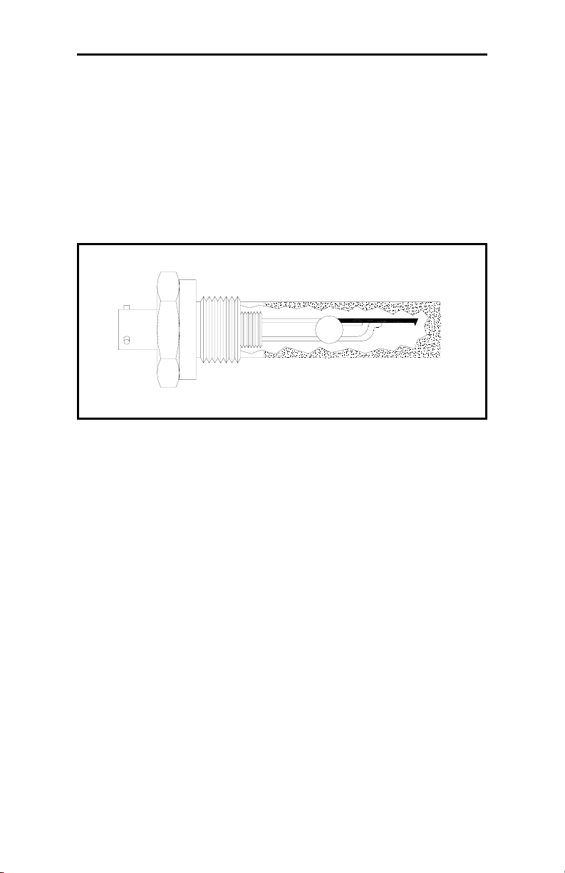
Probes
The moisture probe is the part of the system that comes in contact
with the process, and is usually installed in a sample system. The
Series 35 uses any M Series probe to measure dew point
temperature in °C or °F. A sensor assembly is secured to the
probe mount and protected with a sintered stainless steel shield
(see Figure 1-2 below). Other types of shields are available.
Figure 1-2: The M Series Probe
1-2 Features & Capabilities
Page 11

September 2004
Sample System
The sample system delivers a controlled sample stream at the
specifications of the measurement probe. Typically, the sample
system is kept very simple, with as few components as possible
located upstream of the measurement probe. The sample system
may include a filter to remove particulates from the sample
stream and/or a pressure regulator to control the pressure of the
stream. In general, stainless steel is the preferred material for all
wetted parts in the sample system. The sample system is located
outside of the Series 35 enclosure.
User Program
The Series 35 User Program enables you to change moisture
calibration data, set up and test alarms and recorders, and select a
number of user-defined program functions. The main menu
programming options include:
REFERENCE, ALARMS, RECORDER, TEST, USER, and
FACTORY SETUP me nus.
DP RANGE, CURVE,
All functions and features of the Series 35 User Program are
discussed in Chapter 3, Operation.
Features & Capabilities 1-3
Page 12

September 2004
Chapter 2
Installing the Series 35
This chapter discusses installing the Series 35 in all of its
configurations. Below is a list of procedures that you must follow
to install your unit.
Depending on the type of unit you have, refer to the appropriate
section(s) that follow to install your Series 35 correctly.
Installing your Series 35 consists of the following procedures:
• Choosing a Site for Best Performance
• Precautions for Moisture Probes
• Sample System Guidelines
• Installing the Sample System
• Installing the Probe into the Sample System
• Mounting the Electronics Unit
• Making Wiring Connections to the Electronics Unit.
Proceed to the following sections to install your Series 35.
Installing the Series 35 2-1
Page 13

September 2004
Choosing a Site for Best Performance
Before you receive your Series 35, discuss environmental and
installation factors with a GE Infrastructure Sensing applications
engineer or field sales person. The equipment should be suited to
the application and installation site.
Before installing the unit, read the guidelines below to verify that
you have selected the best installation site.
• Choose an installation site for the probes and sample systems
that is as close to the process line as possible. Avoid long
lengths of connecting tubing. If long distances are
unavoidable, a fast sampling by-pass loop is recommended.
• Do not install any other components, such as filters, upstream
of the probe or sample system unless instructed to do so by GE
Infrastructure Sensing. Many common components, such as
filters and pressure regulators, are not suitable for sample
systems because they have wetted parts that may absorb or
release materials such as moisture into the sample stream.
They may also allow ambient contamination to enter the
sample stream. In general, use stainless steel for all parts in
contact with the sample.
• Observe all normal safety precautions. Use the probes within
their maximum pressure and temperature ratings.
• Although the Series 35 may not need to be accessed during
normal operation, install the electronics unit at a convenient
location for programming, testing and servicing. A control
room or instrument shed are typical locations.
• Locate the electronics unit away from high temperatures,
strong electrical transients, mechanical vibrations, corrosive
atmospheres, and any other conditions that could damage or
interfere with the Series 35 operation. See Chapter 5,
Specifications, for limitations.
2-2 Installing the Series 35
Page 14

September 2004
Choosing a Site for Best Performance (cont.)
•
Observe the proper cable restrictions for the probes. The M
Series probes require specially shielded cable. You can locate
the M Series probes up to 600 meters (2,000 feet) from the
Series 35.
• Protect the probe cables from excessive physical strain
(bending, pulling, twisting, etc.). Do not subject the cables to
temperatures above +105°C (221°F) or below -40°C (-40°F).
Avoid splicing the cables .
Installing the Series 35 2-3
Page 15

September 2004
Precautions for Moisture Probes
The M Series probes consist of an aluminum oxide sensor located
on a connector and covered by a protective stainless-steel shield.
The probe sensor materials and housing maximize durability and
insure a minimum of water absorbing surfaces in the vicinity of
the aluminum oxide surface. A sintered stainless-steel shield is
used to protect the sensor from high flow rates and particulate
matter (other shields are available). The shield should not be
removed except upon advice from GE Infrastructure Sensing.
The sensor has been designed to withstand normal shock and
vibration. Make sure that the active sensor surface is never
touched or allowed to come into direct contact with foreign
objects, since this may adversely affect performance.
Observing these precautions will result in a long and useful probe
life. GE Infrastructure Sensing recommends that probe
calibration be checked routinely, at one-year intervals, or as
recommended by our applications engineers for your particular
application.The probe measures the water vapor pressure in its
immediate vicinity; therefore, readings will be influenced by its
proximity to the system walls, materials of construction, and
other environmental factors. The sensor can be operated under
vacuum or pressure, flowing or static conditions. Observe the
following environmental precautions.
a. Temperature Range: The standard probe is operable
from-110 to +70°C (-166 to 158°F).
b. Moisture Condensation: Be sure the process/ambient
temperature is at least 10°C higher than the dew/frost point
temperature. If this condition is not maintained, moisture
condensation could occur on the sensor or in the sample
system, which will cause reading errors. If this happens,
refer to the Probe Clea nin g Procedure in Appendix A.
2-4 Installing the Series 35
Page 16

September 2004
Precautions for Moisture Probes (cont.)
c. Static or Dynamic Use: The sensor performs equally well
in still air or where considerable flow occurs. Its small size
makes it ideal for measuring moisture conditions within
completely sealed containers or dry boxes. It also performs
well at gas flow rates as high as 10,000 cm/sec, and liquid
flow rates up to 10 cm/sec. Refer to Appendix A for the
maximum flow rates in gases and liquids.
d. Pressure: The moisture probe always senses the existing
water vapor pressure, regardless of the total ambient
pressure. The moisture sensor measures water vapor under
vacuum or high pressure conditions from as little as 5
microns of Hg to as high as 5,000 psi total pressure.
e. Long-Term Storage & Operational Stability: Sensors
are not affected by continuous abrupt humidity changes or
damaged by exposure to saturation conditions, even when
stored.
f. Freedom from Interference: The sensor is completely
unaffected by the presence of a wide variety of gases or
organic liquids. Large concentrations of hydrocarbon
gases, Freon™, carbon dioxide, carbon monoxide, and
hydrogen have no effect on sensor water vapor indications.
The sensor operates properly in a multitude of gaseous or
non-conductive liquid environments.
g. Corrosive Materials: Avoid all materials that are
corrosive or otherwise damaging to aluminum or
aluminum oxide. These include strongly acidic or basic
materials and primary amines.
Installing the Series 35 2-5
Page 17

September 2004
Sample System Guidelines
A sample system, although not mandatory, is highly
recommended for moisture measurement. The purpose of a
sample system is to condition or control a sample stream to
within the specifications of the probe. The application
requirements determine the design of the sample system. GE
Infrastructure Sensing applications engineers will make
recommendations based on the following general guidelines.
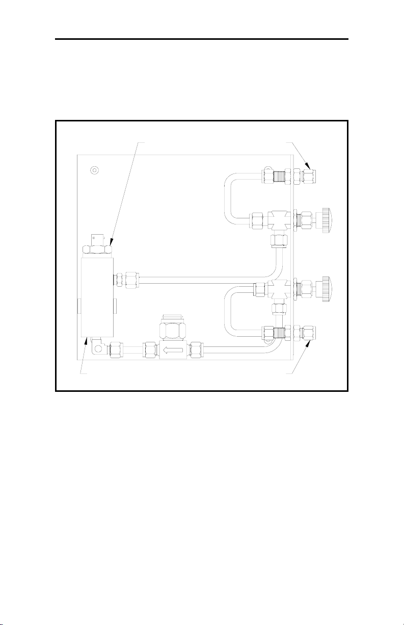
Typically, sample systems should be kept very simple.They
should contain as few components as possible and all or most of
those components should be located downstream of the
measurement probe. Figure 2-1 on page 2-7 shows a simple
sample system consisting of a general-purpose sample cell, a
filter, and two shut-off valves, one at the inlet and one at the
outlet.
The sample system components should not be made of any
material that will affect measurements. A sample system may
include a filter to remove particulates from the sample stream or a
pressure regulator to reduce or control the pressure of the stream.
However, most common filters and pressure regulators are not
suitable for sample systems because they have wetted parts that
may absorb or release components (such as moisture) into the
sample stream. They may also allow ambient contamination to
enter the sample stream In general, you should use stainless steel
material for all wetted parts.
2-6 Installing the Series 35
Page 18
September 2004
Sample System Guidelines (cont.)
Note: The actual sample system design is dependent on the
application requirements.
Probe Outlet
Sample C ell
Inlet
Figure 2-1: A Typical Moisture Sample System
Installing the Series 35 2-7
Page 19

September 2004
Installing the Sample System
The sample system is usually fastened to a metal plate that has
four mounting holes. GE Infrastructure Sensing also provides the
sample system in an enclosure if requested. Outline and
dimension drawings are included with all GE Infrastructure
Sensing sample systems.
Follow the steps below to mount the external sample system and
connect it to the process:
1. Mount the sample system plate or enclosure with four bolts,
one in each corner.
2. Connect the process supply and return lines to the sample
system inlet and outlet using the appropriate stainless steel
fittings and tubing.
Caution!
Do not start flow through the sample system until the
probe has been properly installed.
2-8 Installing the Series 35
Page 20

September 2004
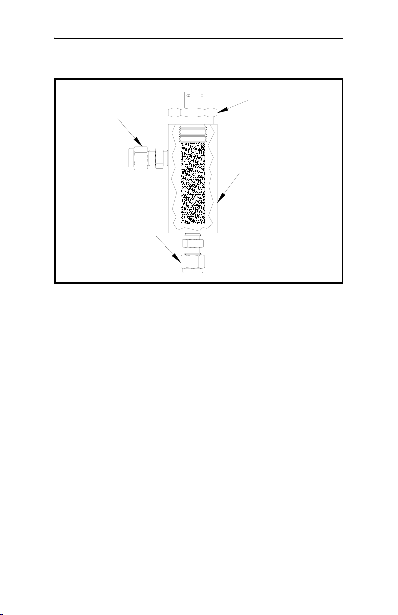
Installing a Probe in the Sample System
The sample system protects the probe from any damaging
elements in the process. The probe must be inserted into the
cylindrical shaped container called the sample cell that is
included as part of the sample system.
M2 probes have 3/4-16 straight threads with an o-ring seal to
secure the probe either into the sample system or directly into the
process line. Other mounts are available for special applications.
Caution!
If mounting the probe directly into the process line,
consult GE Infrastructure Sensing for proper installation
instructions and precautions.
Follow the steps below to install the probe into the external
sample cell.
1. Insert the probe into the sample cell so it is perpendicular to
the sample inlet.
2. Screw the probe into the receptacle fitting, making sure not to
cross the threads.
3. Tighten the probe securely.
Note: Do not over-tighten the probe, or the o-ring seal may be
damaged.
Figure 2-2 on page 2-10 shows a typical probe installation, with
the probe mounted in a sample cell.
Note: For maximum protection of the aluminum oxide moisture
sensor, the protective shield should always be left in place.
Installing the Series 35 2-9
Page 21
September 2004
Installing a Probe in the Sample System (cont.)
Probe
Inlet
Sample Cell
Outlet
Figure 2-2: A Typical Probe Installation
2-10 Installing the Series 35
Page 22

September 2004
Mounting the Electronics Unit
The rack mount Series 35 may be mounted into a standard 19”
rack, the panel mount Series 35 may be mounted into a
rectangular cutout on most instrument panels, and the
weatherproof Series 35 may be mounted on any vertical wall. See
Appendix B, Outline and Installation Drawings, for details.
To install the panel-mount unit:
1. Remove the nuts and washers from the four mounting screws
on the front panel of the unit.
2. Slide the unit into the panel cutout.
3. Install the washers and nuts on the mounting bolts, and tighten
them securely.
To install the rack-mount unit:
1. Insert four mounting screws into the front panel of the unit.
2. Slide the unit into the rack.
3. From behind the rack, install the washers and nuts on the
mounting screws and tighten them securely.
To install the weatherproof unit:
1. Position the unit against a flat, vertical mounting surface (i.e.,
a structure wall). Mark and drill appropriate size holes to
accommodate the mounting bolts.
2. Insert the four mounting bolts into the four mounting holes of
the weatherproof enclosure.
3. Place the enclosure against the mounting surface so that the
four bolts enter the pre-drilled holes. From behind the
mounting surface, install washers and nuts on the mounting
bolts and tighten them securely .
Installing the Series 35 2-11
Page 23

September 2004
Making Wiring Connections to the Electronics Unit
This section covers the following topics:
• precautions for modified or non-GE Infrastructure Sensing
cables
• connecting the probe
• connecting the alarms
• connecting a recorder output device
• connecting an auxiliary input
• connecting power to the unit
• performing an MH/calibration test adjustment
IMPORTANT: To maintain good contact at each terminal block
and to avoid damaging the pins on the connector,
pull the connector straight off (not at an angle),
make cable connections while the connector is
away from the unit, and push the connector
straight on (not at an angle) when the wiring is
complete.
2-12 Installing the Series 35
Page 24

September 2004
Modified or Non-GE Infrastructure Sensing Cables
Many customers must use pre-existing cables, or in some cases,
modify the standard GE Infrastructure Sensing-supplied moisture
cable to meet special needs. If you prefer to use your own cables
or to modify our cables, observe the precautions listed below. In
addition, after connecting the moisture probe, you must perform a
calibration adjustment as described on 22 to compensate for any
electrical offsets.
IMPORTANT: GE Infrastructure Sensing cannot guarantee
operation to the specified accuracy of the Series
35 unless you use GE Infrastructure Sensingsupplied hygrometer cables.
• Use cable that matches the electrical characteristics of the GE
Infrastructure Sensing cable (contact the factory for specific
information on cable characteristics). The cable must have
individually shielded wire pairs. A single overall shield is
incorrect.
• If possible, avoid all splices. Splices impair performance.
When possible, instead of splicing, coil the excess cable.
• If you must splice cables, be sure the splice introduces
minimum resistive leakage or capacitive coupling between
conductors.
• Carry the shield through any splice. A common mistake is to
not connect the shields over the splice. If you are modifying a
GE Infrastructure Sensing cable, the shield will not be
accessible without cutting back the cable insulation. Also, do
not ground the shield at both ends. Only ground the shield at
the hygrometer end of the cable.
Installing the Series 35 2-13
Page 25
September 2004
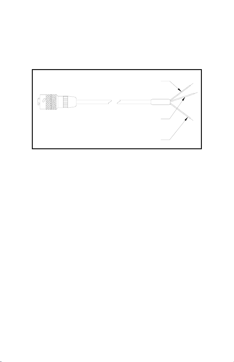
Connecting the Probe
The moisture probe must be connected to the Series 35
electronics with a continuous run of GE Infrastructure Sensing
two-wire shielded cable (see Figure 2-3 below).
Red
Shield
Green
Figure 2-3: Two-Wire Shielded Cable
Be sure to protect cables from excessive strain (bending, pulling,
etc.) Do not subject cables to temperatures above +105°C (221°F)
or below -40°C (-40°F). Standard cable assemblies (including
connectors) can be ordered from GE Infrastructure Sensing in any
length up to 600 meters (2,000 feet).
Follow the steps below to connect the probe to the electronics:
1. Make sure the power is disconnected from the Series 35.
2. Connect the probe cable to the terminal block on the Series 35
electronics, as shown in Table 2-4 on page 2-15 and the
interconnection diagrams in Appendix B.
3. Connect the cable to the probe by inserting the bayonet-type
connector onto the probe and twisting the shell clockwise until
it snaps into a locked position.
2-14 Installing the Series 35
Page 26

September 2004
Connecting the Probe (cont.)
IMPORTANT: To maintain good contact at each terminal block
and to avoid damaging the pins on the connector,
pull the connector straight off (not at an angle),
make cable connections while the connector is
away from the unit, and push the connector
straight on (not at an angle) when the wiring is
complete.
Table 2-4: Probe Connections
Connect: To PROBE Terminal Block:
Red (H2) wire pin #1
Shield pin #2
Green (H1) wire pin #3
Installing the Series 35 2-15
Page 27

September 2004
Connecting the Alarms
The Series 35 has one fault alarm, and two optional alarms that
can be configured as high or low; that is, the contacts can be
programmed to trip when the measured reading is over or under
the alarm setpoint. The fault alarm, if enabled, will trip when
there is a power failure, when a calibration error or a range error
occurs, when there is a signal fault, or when the system is reset by
the watchdog function.
Note: The Watchdog Function is a supervisory circuit that
automatically resets the User Program in the event of a
system error (see Setting Up Alarm Relays in Chapter 3).
Connecting the High and Low Alarms
The Series 35 has optional dual alarm relays available.
Hermetically-sealed alarm relays are also optionally available.
Each alarm relay is a single-pole, double throw contact set that
has the following contacts:
• Normally Open (NO)
• Armature Contact (A)
• Normally Closed (NC)
Make connections to Alarm relays A and B using the terminal
block on the Series 35, as shown in Table 2-5 on page 2-17 and
the interconnection diagrams in Appendix B.
Note: For Eur opean applicatio ns, the voltage levels at the alarm
contacts must be less than 100 VRMS.
IMPORTANT: To maintain good contact at each terminal block
and to avoid damaging the pins on the connector,
pull the connector straight off (not at an angle),
make cable connections while the connector is
away from the unit, and push the connector
straight on (not at an angle) when the wiring is
complete.
2-16 Installing the Series 35
Page 28

September 2004
Connecting the Alarms (cont.)
Table 2-5: High & Low Alarm Connections
Connect Alarm A: To ALARM A Terminal Block:
NC Contact pin #4
NO Contact pin #5
A Contact pin #6
Connect Alarm B: To ALARM B Terminal Block:
NC Contact pin #7
NO Contact pin #8
A Contact pin #9
Connecting the Fault Alarm
The fault alarm connections are on the “OUT” connector, pins 1,
2, and 3. Pins 1 and 3 provide a “normally closed” contact. When
the Series 35 is operating in a non-fault state, the contact between
pins 1 and 3 is energized (open) to remain open. When a fault
occurs or power is lost, the contact between pins 1 and 3 is deenergized (closed). Pins 2 and 3 work in the opposite way. (Refer
to Chapter 3, Operating the Series 35, to enable the fault alarm.)
Make connections to the fault alarm relay using the terminal
block on the back of the Series 35 (or on the side of a benchmount unit), as shown in T able 2-6 below and the interconnection
diagrams in Appendix B.
Table 2-6: Fault Alarm Connections
Connect Fault Alarm: To FAULT ALARM Terminal Block:
NC Contact pin #1
NO Contact pin #2
A Contact pin #3
Note: For Eur opean applicatio ns, the voltage levels at the alarm
contacts must be less than 100 VRMS.
Installing the Series 35 2-17
Page 29

September 2004
Connecting a Recorder Output Device
IMPORTANT: The following instructions apply to Series 35
models with Output Board 703-1 175. For models
with Output Board 703-1180, see Appendix F.
The Series 35 has one recorder output, which is isolated. This
output provides either a current or voltage signal, which is set
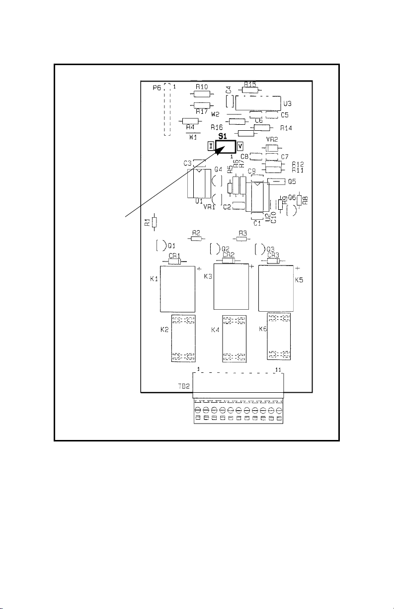
using switch S1 on the output circuit board (see Figure 2-7 on
page 2-19 for the location of S1 ).
Although this switch is normally set at the factory to provide a
current output signal, the setting should be checked before
making any recorder output connections.
Use the following sections to check or reset the S1 setting and
connect an output device.
Checking or Resetting Switch S1
1. Turn off the Series 35 and disconnect power before opening
the unit.
!WARNING!
YOU MUST TURN OFF AND UNPLUG THE SERIES 35
BEFORE YOU CONTINUE WITH THE FOLLOWING STEPS.
2. T o access the output circuit board, remove the screws from the
Series 35 enclosure and remove the cover.
3. Locate switch S1 on the output circuit board (see Figure 2-7
on page 2-19).
4. Set switch S1 to the appropriate position: “I” for current
output or “V” for voltage output.
5. Replace the enclosure cover and install the screws.
2-18 Installing the Series 35
Page 30
September 2004
Connecting a Recorder Output Device (cont.)
Switch S1
Figure 2-7: S1 Location on 703-1175 Output Board
Installing the Series 35 2-19
Page 31

September 2004
Connecting a Recorder Output Device (cont.)
IMPORTANT: To maintain good contact at each terminal block
and to avoid damaging the pins on the connector,
pull the connector straight off (not at an angle),
make cable connections while the connector is
away from the unit, and push the connector
straight on (not at an angle) when the wiring is
complete.
Connecting an Output Device
After you check or reset the switch S1 setting, you can connect a
recorder, computer, or other suitable device to the terminal block
on the back of the Series 35 (or on the side of a bench-mount
unit), as shown in T able 2-4 on page 2-20 and the interconnectio n
diagrams in Appendix B.
Table 2-8: Recorder Output Connections
Connect: To REC OUT Terminal Block:
Out (+) pin #10
Return (-) pin #11
Connecting an Auxiliary Input
The Series 35 can accept one auxiliary input. Connect the input to
the IN terminal block as shown in Table 2-5 below and the
interconnection diagrams in Appendix B.
Table 2-9: Auxiliary Input Connections
Connect: To IN Terminal Block:
Out (+) pin #7
Return (-) pin #8
Power (+V) pin #9
2-20 Installing the Series 35
Page 32

September 2004
Connecting Power to the Unit
GE Infrastructure Sensing supplies a molded plug and cord for
AC power connections in rack, bench and panel mount units;
however, you must supply the p ower cable for 24 VDC units and
weatherproof units.
Refer to the interconnection diagrams in Appendix B to make AC
and DC power connections to the Series 35 electronics.
After you make power connections to the electronics unit,
connect the power cord to an appropriate source, and turn the
power on. The Series 35 displays “Loading....” while it initializes,
then returns to whatever it displayed when it was last turned off.
!WARNING!
IF YOU HAVE A DIVISION 2 UNIT, DO NOT MAKE OR
BREAK ELECTRICAL CONNECTIONS IN A HAZARDOUS
ENVIRONMENT.
IMPORTANT: For compliance with the European Union’s Low
Voltage Directive (IEC 61010), this unit requires
an external power disconnect device such as a
switch or circuit breaker. The disconnect device
must be marked as such, clearly visible, directly
accessible, and located within 1.8 m (6 ft.) of the
MMS 35. The power cord is the main disconnect
device.
Installing the Series 35 2-21
Page 33

September 2004
Performing an MH Calibration/Test Adjustment
If you modify the supplied cables or do not use standard GE
Infrastructure Sensing-supplied cables, you must perform a
calibration test/adjustment to test the cable and, if necessary,
compensate for any error or offset introduced by splicing or long
cable lengths. This procedure is also recommended for testing the
installation of GE Infrastructure Sensing cables.
Use the following steps to perform a calibration adjustment:
Preliminary Steps:
1. Power up the Series 35.
2. Set up the screen to display MH.
3. Make sure high, low and zero reference values are recorded on
the sticker located on the inside chassis of the Series 35, or on
the Data Information Sheet provided in Appendix D.
Calibration Procedure:
1. Disconnect the probe from the cable (leave the probe cable
connected to the Series 35) and verify that the displayed MH
value equals the zero reference value within ±0.0003 MH.
a. If this reading is within specification, no further testing is
necessary.
b. If the reading is less than the specified reading (previous
recorded zero reference value ±0.0003 on sticker), add this
difference to the low reference value.
c. If the reading is greater than the specified reading
(previous recorded zero reference value ±0.0003 on
sticker), subtract this difference from the low reference
value.
2. Note the final corrected low reference value and record it
2-22 Installing the Series 35
Page 34

September 2004
Performing an MH Calibration/Test Adjustment (cont.)
3. Reprogram the Series 35 with the new (corrected) low
reference value (if required), as described in “Entering
Moisture Reference Values” on page 3-13.
4. Verify that the probe cable is not connected to the probe.
5. Note the zero reference readings and verify that the readings
are now within ±0.0003 MH.
6. Fill out a new high and low reference sticker with the final
low reference value and/or record the information on the Data
Information Sheet provided in Appendix D. Make sure you
record the information below:
HIGH REF = ORIGINAL VALUE
LOW REF = NEW CORRECTED VALUE
ZERO REF=ORIGINAL RECORDED VALUE
7. Reconnect the cable to the probe.
Note: If the cables are ever changed in any way, repeat this
procedure for maximum accuracy.
The Series 35 is now ready for operation. Proceed to Chapter 3,
Operating the Series 35, for instructions.
Installing the Series 35 2-23
Page 35

September 2004
Chapter 3
Operating the Series 35
The Series 35 has been factory-programmed and set up to begin
taking measurements as soon as it is powered on. This chapter
describes starting the unit and beginning operation of the unit as
quickly as possible. In addition, setting up the alarm relays, a
recorder, and the user-defined functions are covered.
This chapter explains the following specific procedures. Proceed
to the appropriate section to operate the Series 35.
• Getting Started - Use this section to get the Series 35 operating
as quickly as possible.
• Changing the Measurement Display - Use this section to set up
the display screen for the desired measurement.
• Setting Up Alarm Relays - Use this section to enable the fault
alarm or to set up the optional high and low alarm relays.
• Setting Up a Recorder - Use this section to set up a recorder
output device.
• Setting Up User-Defined Functions - Use this section to define
and set up a variety of program functions to enhance the
usability of the Series 35.
Operating the Series 35 3-1
Page 36

September 2004
Getting Started
Since the calibration data has already been set up at the factory,
you can begin taking measurements as soon as you power up the
Series 35. Proceed to the appropriate section to power up your
unit and verify that it is working correctly:
• Powering up the Series 35
• Entering Data into the User Program
• Verifying and Changing Factory Setup Data
To set up alarms, set up a recorder device, change the setup data,
or configure the display, see the instructions on page 3-4 to learn
how to use the Series 35 keypad for entering data into the User
Program.
3-2 Operating the Series 35
Page 37

September 2004
Powering Up the Series 35
After making the power connections to the electronics unit as
described in Chapter 2, Installing the Series 35, connect the
power cord to an appropriate power source. To power up the
Series 35, flip the
front panel, to the
IMPORTANT: Weatherproof MMS 35 units have no power
IF YOU HAVE A DIVISION 2 UNIT, DO NOT MAKE OR
BREAK ELECTRICAL CONNECTIONS IN A HAZARDOUS
Immediately after the power is applied, the Series 35 displays the
“Loading...” message to indicate that the system is loading
calibration and reference data. After this data is loaded, the Series
35 automatically calibrates (Autocal) the moisture circuitry . After
the Autocal finishes, the Series 35 display returns to whatever it
displayed when it was last powered down.
POWER switch, located on the left side of the
ON position.
switch, and the power switch on Division 2
modified units is disabled. Both units power up
as soon as line power is applied.
!WARNING!
ENVIRONMENT.
Operating the Series 35 3-3
Page 38

September 2004
Entering Data into the User Program
The Series 35 User Program allows you to change factory set-u p
data, set up alarms and a recorder output device, and set up userdefined program functions. In order to enter and exit the User
Program, move through the main menus, and enter numeric data
into the User Program, you must first learn how to use the
programming keys located on the front panel of the Series 35.
Use the appropriate sections that follow to learn how to enter data
into the User Program.
Using the Programming Keys
The front panel of the Series 35 contains the following four keys
for entering data into the User Program:
• ENTER - Use this key to select a menu option, to switch from
viewing to editing data, to move to the next digit position
during numeric entry, and to confirm an entry.
• ESC - Use this key to cancel an entry and to back out of a
menu option.
• U - Use this key to scroll upward through the menu options,
and to increase the value during numeric entry.
• V - Use this key to scroll downward through the menu
options, and to decrease the value during numeric entry.
3-4 Operating the Series 35
Page 39

Entering and Exiting the User Program
September 2004
This section describes how to use the
[ENTER] and [ESC] keys to
enter and exit the User Program. Refer to Table 3-1 below for the
key sequence for entering the User Program main menu.
Note: The first two steps must be performed within 5 seconds of
each other or the unit will time out and return to
displaying measurements.
Table 3-1: Entering the User Program
Press These Keys: To Display:
[ESC]
1.
2. [ENTER], [ESC]
To exit the User Program, press the
displays. Then press the
[ENTER] key to return to displaying
PROGRAM MENU
displays for 1 sec, then:
[ESC] key until RUN?
ESC
DP RANGE
measurements.
Operating the Series 35 3-5
Page 40

September 2004
Moving Through the User Program
Use the arrow keys to scroll through the eight Main Menu opt ions
as follows (refer to the menu maps in Appendix C as a guide):
• DP RANGE - use to enter high and low dew points for the
calibration curve
• CURVE - use to enter a value for each point on the calibration
curve
• REFERENCE - use to enter high and low reference values for
moisture measurement
• ALARMS - use to set up the high, low, and fault alarms
• RECORDER - use to set up the recorder output range,
measurement mode, and zero/span values
• TEST - use to test and adjust the alarms and the recorder
output (see Chapter 4, Troubleshooting, for details)
• USER - use to set up user-defined program functions, such as
offset value, constant pressure, PPMv constant multiplier,
Autocal interval, computer enhanced response, backlight,
range and calibration error handling
• FACTORY SETUP - for factory use only
Note: While in programming mode, the Series 35 suspends
taking measurements.
3-6 Operating the Series 35
Page 41

September 2004
Entering Numeric Data
To enter numbers one digit at a time, use the arrow keys to scroll
to the desired number (0 to 9 or the decimal point), then press the
[ENTER] key to move to the next digit position. Repeat this
procedure until all numbers are entered.
Note: From the programming mode, once an arrow key is
pressed, you are in edit mode. Pressing
[ESC] terminates
the edit mode. While in edit mode, check all characters
before pressing the
[ENTER] key to move on to the next
digit position.
Refer to the sections that follow to enter data into the User
Program’s main menu options.
Operating the Series 35 3-7
Page 42

September 2004
Verifying and Changing Factory Setup Data
Use this section to make sure factory setup data is correct and to
make any necessary changes to the setup data.
Note: Record all calibration data on the Data Information Sheet
in Appendix D.
In order for the Series 35 to take accurate measurements, it must
have the correct moisture calibration data entered into its
memory. All of the necessary data has been entered into your
Series 35 at the factory; however, the data should be checked for
accuracy.
To verify data, check the following:
• dew point range
• calibration data
• high and low reference values
Use the appropriate sections that follow to verify and/or change
the moisture calibration data.
3-8 Operating the Series 35
Page 43

September 2004
Entering the Dew Point Range
The DP Range is used to enter high and low dew point values.
This range is used by the Series 35 to determine the number of
points on the calibration curve.
Note: The high and low dew points are listed on the Moisture
Probe Calibration Data Sheet located in the probe box.
Changing the DP Range affects the calibration data.
The default values are: Low: –110, High: +20
DP RANGE
In the main menu, use the arrow
keys to scroll to this prompt,
[ENTER] key.
Hi DP
Hi DP+20°C
then press the
Use the arrow keys to scroll to
Hi DP, then press [ENTER].
Use the arrow keys to scroll to
the desired dew point value, then
[ENTER].
press
Repeat this procedure to enter the low dew point value, then press
[ESC] key until you return to the main menu.
the
Operating the Series 35 3-9
Page 44

September 2004
Entering Calibration Data
After entering the high and low dew point values, use the
CURVE
option to enter calibration data for the moisture probe or the
auxiliary input. Refer to the appropriate section that follows to
program the Series 35.
To Enter Moisture Probe Calibration Data:
Moisture probe calibration data is always taken at fixed dew point
values in 10ºC intervals. After entering the high and low dew
point values, the Series 35 determines the appropriate number of
data points for the moisture probe, so only the MH (raw data)
values need be entered. The Series 35 automatically requests the
MH value for the minimum dew point and keeps requesting data
in 10ºC increments until the maximum dew point is reached. The
MH values are found on the Calibration Data Sheet supplied with
the moisture probe.
CURVE
In the main menu, use the arrow
keys to scroll to this prompt,
[ENTER] key.
MH CURVE
then press the
Use the arrow keys to scroll to
MH CURVE and press [ENTER].
ENTER MH CURVE
ENTER PROBE S/N
Use the arrow keys to scroll to
ENTER MH CURVE or
either
ENTER PROBE S/N. Press
ENTER] at your choice.
[
If you select ENTER MH CURVE:
-110°CMH 0.1890
To view the curve, pre ss the
arrow keys to scroll through the
values. To edit a value, press
[ENTER], then either arrow key
to delete the present value. Use
the arrow and
[ENTER] keys to
change the value one digit at a
time, then press
3-10 Operating the Series 35
[ENTER] twice.
Page 45

September 2004
Entering Calibration Data (cont.)
Note: To abort the editing function without changing the value,
press the
[ESC] key.
Repeat this procedure for each point on the MH Curve, then press
[ESC] until you return to the CURVE menu.
If you select ENTER PROBE S/N:
xxxxxx S/N
The unit displays the current
serial number. To edit the
number, press an arrow key. A
blinking cursor appears at the
left-most digit. Use the arrow
keys to scroll to the desired
value, and the
[ENTER] keys to
move the cursor to the next digit.
Repeat until you have entered all
six serial number digits. Then
[ENTER] to confirm the
press
change or [ESC] to cancel the
change.
To Enter Auxiliary Input Calibration Data:
The Series 35 can have up to ten (10) calibration data points for
its Auxiliary input. Each data point requires an electrical current
value (0-20 mA) with a corresponding scale value.
CURVE
In the main menu, use the arrow
keys to scroll to this prompt,
then press the
[ENTER] key.
AUX CURVE
Operating the Series 35 3-11
Use the arrow keys to scroll to
AUX CURVE and then press the
[ENTER] key.
Page 46

September 2004
Entering Calibration Data (cont.)
To Enter Auxiliary Input Calibration Data (cont.):
#Aux Pts = 3
AxUnit#DecPlc 3
Edit Pt# 1
#1mA = 4.000
Use the arrow keys to scroll to
the desired number of points,
then press the
[ENTER] key.
Use the arrow keys to scroll to
the desired number of decimal
places for the scale value, then
press the
[ENTER] key.
Use the arrow keys to scroll to
the desired point, then press the
[ENTER] key.
Press either arrow key to delete
the present mA value and enter
edit mode. Use the arrow and
[ENTER] keys to enter a new
value, one digit at a time, then
[ENTER] twice.
press
#1F = +0.00
Press either arrow key to delete
the present scale value and enter
edit mode. Use the arrow and
[ENTER] keys to enter a new
value, one digit at a time, then
[ENTER] twice to proceed
press
to the next data point.
Repeat the above procedure for each point on the Auxiliary
Curve, then press
3-12 Operating the Series 35
[ESC] until you return to the main menu.
Page 47

September 2004
Entering High and Low Reference Values
IMPORTANT: Do not change these reference values unless
instructed to do so by GE Infrastructure Sensing.
The Series 35 requires high and low reference values for its
moisture measurement circuitry. These references are factory
calibration values that are specific to each unit. They are listed on
a label located on the inside of the Series 35.
REFERENCE
HYGRO REF
High REF
H2.9999
Low REF
L0.1790
In the main menu, use the arrow
keys to scroll to this prompt,
then press the
[ENTER] key.
Press the [ENTER] key again.
Press either arrow key to scroll
High REF edit mode, then
to the
[ENTER].
press
Use the arrow and [ENTER]
keys to change the value, one
digit at a time, then press
[ENTER] twice.
Press either arrow key to scroll
Low REF edit mode, then
to the
press the
[ENTER] key.
Use the arrow and [ENTER] keys
to change the value, one digit at
a time, then press the [ENTER]
key twice.
Note: To abort the editing function without changing the value,
press the [ESC] key.
[ESC] until you return to the main menu.
Press
Operating the Series 35 3-13
Page 48

September 2004
Changing the Measurement Display
Use this section to set up the Series 35 display screen for the
measurement modes you want to display. The front panel of the
Series 35 contains four (4) display keys that let you quickly
change the measurement display during operation.
The four display keys are as follows:
• HYGRO - press this key to display and scroll through all of
the available moisture measurement units (DP/C, DP/F, PMv,
MH)
• Pconst - press this key to display and scroll through all of the
available constant pressure units (PSG, Bar, KPAg, Kcmg)
• ALARM - press this key to display and scroll through the
status and set points of alarm relays A and B, as well as the
status of the fault alarm relay
• AUX IN - press this key to display the auxiliary input
measurement in either milliamps (mA) or a user-defined
function (XF - Auxiliary Function)
Once you select a specific display mode, that display remains on
the screen until another display mode is chosen, or until you enter
programming mode. Upon exiting programming mode and
returning to
display mode previously selected.
3-14 Operating the Series 35
RUN mode, the screen automatically returns to the
Page 49

September 2004
Setting Up the Alarm Relays
The Series 35 has one fault alarm and two optional high/low
alarms. Use this section to enable the fault alarm or to set up the
optional high/low alarm relays. (Refer to Table 3-2 on page 3-16
for a list of possible alarm conditions.)
High/Low Alarms:
these alarm relays can be programmed to trip when the measured
reading is over (high) or under (low) the alarm setpoint. To set up
a high or low alarm, do the following:
• enable or disable the alarms
• set the alarm measurement mode
• set the alarm units
• configure the alarm as high or low
• set the alarm units and enter the setpoint
Fault Alarm:
To ensure failsafe operation during a power loss, the behavior of
the fault alarm relay is the opposite of the high/low alarm relays.
The fault alarm relay is energized under non-fault conditions, and
de-energized under fault conditions.
When the Series 35 is operating in a non-fault state, the normally
closed (NC) contact between pins 1 and 3 is energized to remain
open. When a fault occurs or power is lost, the contact between
pins 1 and 3 is de-energized and closes. The normally-open (NO)
contact between pins 2 and 3 is energized closed in a non-fault
state, and de-energized open when a fault occurs or power is lost.
The fault alarm, if enabled, trips during the following conditions:
• when there is a power failure
• when a calibration error or a range error occurs
Operating the Series 35 3-15
Page 50

September 2004
Setting Up the Alarm Relays (cont.)
Fault Alarm (cont.):
• when there is a signal fault
• when the system is reset by the watchdog function.
Note: The Watchdog Function is a supervisory circuit that
automatically resets the User Program in the event of a
system error.
Table 3-2: Possible Alarm Conditions
Alarm
Type
Cont:NCNONCNONCNO
Alarm Aopen closed closed open closed open
Alarm Bopen closed closed open closed open
Fault
Alarm
Fault
Conditions
Energized De-Energized De-Energized
Energized De-Energized De-Energized
closed open open closed closed open
De-Energized Energized De-Energized
Non-Fault
Conditions Loss of Power
3-16 Operating the Series 35
Page 51

September 2004
Enabling or Disabling the Alarms
If alarm A or alarm B is disabled, the display returns to the alarm
menu; if alarm A or alarm B is enabled, the alarm mode options
are displayed. The fault alarm options are limited to the “Enable”
or “Disable” choices. After the fault alarm is enabled or disabled,
the display returns to the alarm menu.
Note: Be sure to record all entered output data in the Data
Information Sheet in Appendix D.
ALARMS
In the main menu, use the arrow
keys to scroll to this prompt,
[ENTER] key.
Alarm A
then press the
Use the arrow keys to scroll to
the desired alarm, then press
[ENTER].
Enable Alarm
Use the arrow keys to scroll to
the desired choice, then press
[ENTER].
Selecting the Measurement Mode
Select “ALM HYG” if you want the alarm to respond to
measurements taken from the probe input connection; select
“ALM AUX” if you want the alarm to respond to measurements
taken from the auxiliary input connection.
ALM HYG
ALM AUX
Use the arrow keys to scroll to
the desired measurement option,
then press
[ENTER].
Operating the Series 35 3-17
Page 52

September 2004
Selecting the Measurement Units
The next set of prompts that appears depends on the alarm mode
selected. Choose the units to which you want the alarm to
respond. Refer to the appropriate section below and to Table 3-3
on page 3-19 for a list of the available units.
If you selected
ALM HYGDP/°F
“ALM HYG” the following prompts appear:
Use the arrow keys to scroll to
the desired measurement unit,
ALM HYGDP/°C
ALM HYGDVM
ALM HYGMH
ALM HYGPMv
If you selected
then press
“ALM AUX” you can choose either a mA
[ENTER].
(milliamp) value or a user-defined XF (Auxiliary Function)
value.
ALM AUXmA
Use the arrow keys to scroll to
the desired value type, then
ALM AUXXF
press
[ENTER].
3-18 Operating the Series 35
Page 53

Selecting the Measurement Units (cont.)
Table 3-3: Alarm/Recorder Measurement Units
Measurement Mode Units
DP/°F - dew point in °F
DP/°C - dew point in °C
Hyg - Hygrometry
Aux - Auxiliary
DVM - internal voltage signal
MH - raw signal from sensor
PMv - parts per million by volume
mA - milliamps
XF - user-defined units
September 2004
Operating the Series 35 3-19
Page 54

September 2004
Configuring the Alarm
After selecting the desired measurement units, the following set
of prompts appears:
Low Alarm
Use the arrow keys to choose a
high or low alarm, then press
Hi Alarm
[ENTER]. (A high alarm trips
when a reading is above the
setpoint, while a low alarm trips
when a reading is below the
setpoint.)
Note: The next prompts that appear depend on the selected
alarm measurement mode, alarm measurement units, and
alarm configuration (high or low).
AL:+1.0 DP/°C
Press either arrow key to delete
the current value and enter edit
mode.
AL:+5.0 DP/°C
Enter the alarm setpoint. Use the
arrow and
[ENTER] keys to
change the value one digit at a
time, then press
[ENTER] twice.
If necessary, repeat the above procedure to set up the other alarm;
then press
[ESC] until you return to the main menu.
Note: Be sure to record all entered data in the Data Information
Sheet in Appendix D.
3-20 Operating the Series 35
Page 55

September 2004
Setting Up a Recorder
Use this section to set up the one Series 35 recorder output. To
configure the recorder output signal, do the following:
• select the output signal in milliamps or volts
• select the recorder measurement mode and units
• set the zero and span values
Note: Be sure to record all entered output data in the Data
Information Sheet in Appendix D.
Selecting the Output Signal
Note: Be sure the output signal selected (mA or V) agrees with
the Series 35 recorder switch setting (see Making
Recorder Connections in Chapter 2).
RECORDER
0-20 mA
4-20 mA
0-2 V
Operating the Series 35 3-21
In the main menu, use the arrow
keys to scroll to this prompt,
then press the
Use the arrow keys to scroll to
the desired output range, then
[ENTER].
press
[ENTER] key.
Page 56

September 2004
Selecting the Measurement Mode and Units
Selecting the Measurement Mode
“RCD HYG” if you want the recorder to respond to
Select
measurements taken from the probe input connection; select
“RCD AUX” if you want the recorder to respond to measurements
taken from the auxiliary input connection.
RCD HYG
Use the arrow keys to scroll to
the desired measurement mode,
RCD AUX
then press
[ENTER].
Selecting the Measurement Units
The next set of prompts that appear depends on the measurement
mode selected above for the recorder output. To choose the
desired recorder output measurement units, refer to the
appropriate section below and Table 3-3 on page 3-19 for a list of
the available measurement units.
“RCD HYG” was selected above, the following prompts appear:
If
RCD HYGDP/°F
Use the arrow keys to scroll to
the desired measurement unit,
RCD HYGDP/°C
RCD HYGDVM
RCD HYGMH
then press
[ENTER].
RCD HYGPMv
3-22 Operating the Series 35
Page 57

September 2004
Selecting the Measurement Mode and Units (cont.)
If “RCD AUX” was selected at the initial recorder prompt on
page 3-22, either a mA (milliamp) output value or a user-defined
XF (Auxiliary Function) output value may be chosen.
RCD AUXmA
Use the arrow keys to scroll to
the desired output value, then
RCD AUXXF
press
[ENTER].
Setting the Zero and Span Values
The next set of prompts that appears depend s on the measurement
mode and units previously selected for the recorder.
Ze:-80.0 DP/°C
Ze:+60.0 DP/°C
Sp:+20.0 DP/°C
Press either arrow key to delete
the current zero value and enter
edit mode.
Use the arrow and [ENTER] keys
to change the zero value one
digit at a time, then press
[ENTER] twice to proceed to the
span value.
Press either arrow key to delete
the current span value and enter
edit mode.
Sp:+9.0 DP/°C
Use the arrow and [ENTER] keys
to change the span value one
digit at a time, then press
[ENTER] twice.
[ESC] until you return to the main menu.
Press
Operating the Series 35 3-23
Page 58

September 2004
Setting Up User-Defined Functions
Use this section to set up and define a variety of program
functions to enhance the usability of the Series 35.
USER menu lets you set up the following program functions:
The
• Offset Value
• Constant Pressure
• Automatic Calibration Interval
• Backlight-On Time Interval
• Computer Enhanced Response (optional)
• Range Error Processing
• Calibration Error Processing
• Entering a PPMv Constant Multiplier
Use the appropriate sections that follow to set up the desired
program functions.
3-24 Operating the Series 35
Page 59

September 2004
Entering an Offset Value
Use this option to adjust the displayed dew/frost point reading. A
positive number increases the reading, while a negative number
decreases the reading. The offset value is always displayed in
dew/frost point degrees C.
Note: Be sure to record all entered output data in the Data
Information Sheet in Appendix D.
USER
In the main menu, use the arrow
keys to scroll to this prompt,
[ENTER] key.
OFFSET
OFFSET+5.0°C
then press the
Use the arrow keys to scroll to
“OFFSET,” then press [ENTER].
Press either arrow key to delete
the current value and enter edit
mode.
OFFSET+10.0°C
Use the arrow and [ENTER] keys
to change the value one digit at a
time, then press
After entering the offset value, press
USER menu.
[ESC] until you return to the
[ENTER] twice.
Note: The maximum positive value for the offset is +15.0°C, and
the maximum negative value is -15°C.
Operating the Series 35 3-25
Page 60

September 2004
Entering a Constant Pressure
This option lets you enter a fixed value for the pressure of the
sample gas at the moisture probe location. This value is used to
calculate the moisture content in ppmv. Refer to Table 3-4 below
for a list of the available constant pressure units.
Table 3-4: Constant Pressure Units
Available Units Description of Units
KP PSIg pounds per square inch gauge
KP Bar bars absolute
KP KPAg kilopascals gauge
KP Kcmg kilograms per square centimeter gauge
Note: Be sure to record all entered output data in the Data
Information Sheet in Appendix D.
CONSTANT PRESSUR
In the USER menu, use the
arrow keys to scroll to this
prompt, then press the
[ENTER]
key.
KPPSIg
Use the arrow keys to scroll to
the desired pressure units, then
[ENTER].
press
KP:+ PSG
Press either arrow key to delete
the current value and enter edit
mode.
KP:+500.00 PSG
Use the arrow and [ENTER] keys
to change the value one digit at a
time, then press
After entering the constant pressure value, press
return to the
3-26 Operating the Series 35
USER menu.
[ENTER] twice.
[ESC] until you
Page 61

September 2004
Entering an Automatic Calibration Interval
The Series 35 automatically calibrates itself at user-defined
intervals, to compensate for any drift in the electronics. Normally ,
GE Infrastructure Sensing recommends setting the Autocal
interval to 480 minutes (eight hours). However, a smaller Autocal
interval is beneficial if the Series 35 is exposed to extreme
temperature or weather conditions. Values between 0 and 1440
minutes (14 hours) may be specified for the Autocal interval.
Note: Be sure to record all entered output data in the Data
Information Sheet in Appendix D.
AUTOCAL INTERVAL
In the USER menu, use the
arrow keys to scroll to this
prompt, then press the
key.
ACAL (Mins)0
Press either arrow key to delete
the current value and enter edit
mode.
ACAL (Mins)3.0
Use the arrow and [ENTER] keys
to change the value one digit at a
time, then press
After entering the Autocal interval, press
USER menu.
to the
[ENTER]
[ENTER] twice.
[ESC] until you return
Operating the Series 35 3-27
Page 62

September 2004
Entering an Automatic Calibration Interval (cont.)
After you confirm the Autocal interval and return to the main
menu, the Series 35 immediately performs an Autocal. The next
time the Autocal occurs depends on the length of the time interval
setting.
The Series 35 determines the times of subsequent Autocals by
establishing a fixed schedule, beginning at midnight, using the
specified interval. For example, if you enter a 90-minute time
interval, Autocal occurs 16 times per day
(1 day = 1440 minutes ÷ 90 minutes = 16).
The following fixed schedule applies:
1. 1:30 a.m. 9. 1:30 p.m.
2. 3:00 a.m. 10. 3:00 p.m.
3. 4:30 a.m. 11. 4:30 p.m.
4. 6:00 a.m. 12. 6:00 p.m.
5. 7:30 a.m. 13. 7:30 p.m.
6. 9:00 a.m. 14. 9:00 p.m.
7. 10:30 a.m. 15. 10:30 p.m.
8. 12:00 p.m.(noon) 16. 12:00 a.m.(midnight)
If you enter a time interval not evenly divisible into 1440
minutes, the Series 35 rounds up to the next acceptable interval.
For example, if you set the 90-minute Autocal interval at 6:10
p.m., the next Autocal occurs at 7:30 p.m. (excluding the Autocal
performed when you exit the Autocal menu).
3-28 Operating the Series 35
Page 63

September 2004
Entering a Backlight-On Time Interval
If your Series 35 is equipped with a backlight, you can program
the backlight to turn off automatically after a predetermined time.
If the display does not have the backlight, attempts to access this
option results in an
“Backlight” prompt appears. Values between 0 and 1440
the
minutes (24 hours) may be entered.
“Option Not Available” message; otherwise,
BACKLIGHT
In the USER menu, use the
arrow keys to scroll to this
prompt, then press the
key.
BLITE (Mins)0
Press either arrow key to delete
the current value and enter edit
mode.
BLITE (Mins)0
Use the arrow and [ENTER] keys
to change the value one digit at a
time, then press
After entering the Backlight interval, press
USER menu.
to the
[ENTER]
[ENTER] twice.
[ESC] until you return
Operating the Series 35 3-29
Page 64

September 2004
Setting Up Computer Enhanced Response
Note: This option may not be installed on your Series 35.
Computer Enhanced Response uses a dynamic moisture
calibration technique to extrapolate the moisture level to the end
point, when making measurements in abrupt “dry down”
conditions. The system response time depends on the relative
change in dew point. For a change from ambient moisture levels
to trace levels, the Series 35 can respond in under one minute.
A reasonably constant final dew point and flow rate are needed to
use the computer enhanced response option. The minimum flow
rate is 1 SCFH (500 cc/min).
If your Series 35 is equipped with Computer Enhanced Response,
use this function to enable or disable the feature. If the enhanced
response option is not available, the display will read
Avail.”
Otherwise, the Enhance Response display appears.
Note: Be sure to record all entered data in the Data Information
Sheet in Appendix D.
“Option Not
ENHANCE RESPONSE
In the USER menu, use the
arrow keys to scroll to this
prompt, then press the
[ENTER]
key.
ENHANCE OFF
Use the arrow keys to scroll to
the desired status, then press
ENHANCE ON
[ESC] until you return to the USER menu. After you
Press
activate Computer Enhanced Response, a reverse video
[ENTER].
“E”
symbol appears on the left side of the display as part of the mode.
When the Series 35 determines the final value, the reverse video
“E” changes to a normal “E.”
3-30 Operating the Series 35
Page 65

September 2004
Setting Up Range Error Processing
Range errors occur when an input signal that is within the
capacity of the analyzer is outside the range of the probe
calibration data. The Series 35 displays range errors with an
OVER RANGE or UNDER RANGE message. The error condition
extends to all displayed measurements of that mode. For
example, if dew point displays
PPMv also displays
OVER RANGE.
The User Program permits the selection of the manner in which
errors are handled by the Series 35. To monitor the unit for error
conditions, the fault alarm and/or the recorder output may be used
as external indicators.
OVER RANGE, then moisture in
Refer to T able 3-5 on page 3-32 for a description of each
ERROR
option and the corresponding response of the Series 35.
RANGE
Note: Be sure to record all entered data in the Data Information
Sheet in Appendix D.
RANGE ERROR
In the USER menu, use the
arrow keys to scroll to this
prompt, then press the
[ENTER]
key.
R_ERR = No Response
Use the arrow keys to scroll to
the desired error response mode,
R_ERR = Display
R_ERR = Hi/Lo RCD
R_ERR = Hi/Hi RCD
[ESC] until you return to the USER menu.
Press
then press
[ENTER].
Operating the Series 35 3-31
Page 66

September 2004
Setting Up Range Error Processing (cont.)
Table 3-5: Range Error Response Modes
Option Display Alarm/Recorder
No Action none range error disabled
Display error displayed fault alarm tripped
fault alarm tripped,
recorder output high for
Hi/Lo RCD error displayed
Hi/Hi RCD error displayed
over-range errors,
recorder output low for
under-range errors
fault alarm tripped,
recorder output high for
over-range errors,
recorder output high for
under-range errors
3-32 Operating the Series 35
Page 67

September 2004
Setting Up Calibration Error Processing
A Calibration Error indicates a failure during measurement of
the internal moisture references. During Autocal, internal
references are read repeatedly, and the values measured are
compared to a table of acceptable factory calibration values. Any
deviation from the factory values is calculated and corrected.
Should a reference value fall outside the acceptable range,
CAL ERROR message appears.
a
You can select whether the recorder output will be forced low
(zero value) or high (span value) upon detection of a calibration
error. When a calibration error is detected, the recorder output
remains at the selected limit (low or high) until the error
condition is corrected. Then, an Autocal is then executed or the
system is restarted.
If you attempt to display data while a calibration error is in effect,
“CAL ERROR DP/°C” display appears.
the
Note: Be sure to record all entered data in the Data Information
Sheet in Appendix D.
CAL ERROR
In the USER menu, use the
arrow keys to scroll to this
prompt, then press the
[ENTER]
key.
CAL_ERR = Lo Output
Use the arrow keys to scroll to
the desired selection, then press
CAL_ERR = Hi Output
[ESC] until you return to the USER menu.
Press
Operating the Series 35 3-33
[ENTER].
Page 68

September 2004
Entering a PPMv Constant Multiplier
Use this option to apply a user-defined constant multiplier to the
the PPMv value. Values up to 999.9999 may be entered.
PPMv MULTIPLIER
In the USER menu, use the
arrow keys to scroll to this
prompt, then press the
[ENTER]
key.
KPPMv1.0000
Press either arrow key to delete
the current value and enter edit
mode.
KPPMv2.0000
Use the arrow and [ENTER] keys
to change the value one digit at a
time, then press
[ENTER] twice.
Note: Be sure to record all entered data in the Data Information
Sheet in Appendix D.
After entering the
you return to the
PPMv constant multiplier, press [ESC] until
USER menu.
3-34 Operating the Series 35
Page 69

September 2004
Chapter 4
Troubleshooting and Maintenance
The Moisture Monitor Series 35 is designed to be maintenance
and trouble free. Due to process conditions and other factors,
however, minor problems may occur. This chapter discusses
some of the most commonly encountered problems and the
procedures for correcting them. If you cannot find the
information you need in this chapter, contact GE Infrastructure
Sensing.
Caution!
Do not attempt to troubleshoot the Series 35 beyond the
instructions in this chapter. If you do, you may damage
the unit and void the warranty.
This section includes the following information:
• Common Problems
• Screen Messages
• Replacing the User Program
• Replacing and Recalibrating the Moisture Probes
• Testing the Alarm Relays and Recorder Output
• Adjusting the Recorder Output Zero and Span Values
Common Problems
If the Series 35 measurement readings seem incorrect, there may
be a problem with the probe or another system component.
Table 4-1 on page 4-2 contains some of the most common
measurement problems and suggested ways to resolve them.
Troubleshooting and Maintenance 4-1
Page 70

4-2 Troubleshooting and Maintenance
September 2004
Table 4-1: Solutions to Common Problems
Symptom Possible Cause
Insufficient time for
system to equilibrate.
The dew point at the
sampling point is
Accuracy of moisture
sensor is questioned
different than the dew
point of the main stream.
Sensor or sensor shield
affected by process
contaminant (Appx. A).
Sensor is contaminated
with conductive
particles (Appendix A).
System
Response
Probe reads too
wet during dry
down, or too dry
in wet up
conditions.
Probe reads too wet
or too dry.
Probe reads too wet
or too dry.
Probe reads high
dew point.
Action
Change the flow rate. A change in dew point indicates the
sample system is not at equilibrium, or there is a leak.
Allow sufficient time for sample system to equilibrate and
moisture reading to become steady. Check for leaks.
Readings may be correct if the sampling point and main
stream do not run under the same process conditions. The
different process conditions cause readings to vary. Refer
to Appendix A for more information. If sampling point and
main stream conditions are the same, check sample
system pipes, and any pipe between the sample system
and main stream for leaks. Also, check sample system for
adsorbing water surfaces, such as rubber or plastic tubing,
paper-type filters, or condensed water traps. Remove or
replace contaminating parts with stainless steel parts.
Clean the sensor and the sensor shield as described in
Appendix A. Then reinstall the sensor.
Clean the sensor and the sensor shield as described in
Appendix A, then reinstall the sensor. Also, install a proper
filter (i.e. sintered or coalescing element).
Page 71

Troubleshooting and Maintenance 4-3
Table 4-1: Solutions to Common Problems
Symptom Possible Cause
Sensor is corroded (refer
to Appendix A).
Accuracy of moisture
sensor is questioned
Slow response.
Screen always reads
the wettest (highest)
programmed moisture
calibration value
while displaying
dew/frost point.
Sensor temperature is
greater than 70°C
(158°F).
Stream particles are
causing abrasion.
Slow outgassing of
system.
Sensor is contaminated
with non-conductive
particles (Appendix A).
Probe is saturated.
Liquid water is present
on sensor surface
and/or across electrical
connections.
System
Response
Probe reads too wet
or too dry.
Probe reads too dry. Return the probe to the factory for evaluation.
Probe reads too wet
or too dry.
Return the probe to the factory for evaluation.
Return the probe to the factory for evaluation.
Replace the system components with stainless steel or
electro-polished stainless steel.
Clean the sensor and the sensor shield as described in
Appendix A. Then reinstall the sensor.
Clean the sensor and the sensor shield as described in
Appendix A. Then reinstall sensor.
Action
September 2004
Page 72

4-4 Troubleshooting and Maintenance
Table 4-1: Solutions to Common Problems
September 2004
Symptom Possible Cause
Shorted circuit on
Screen always reads
the wettest (highest)
programmed moisture
calibration value
while displaying
the dew/frost point.
Screen always reads
the driest (lowest)
programmed moisture
calibration value
while displaying
the dew/frost point.
sensor.
Sensor is contaminated
with conductive particles
(refer to Appendix A).
Improper cable
connection.
Open circuit on the
sensor.
Non-conductive
material is trapped under
the contact arm of the
sensor.
Improper cable
connection.
System
Response
Action
Run “dry gas” over sensor surface. If high reading persists,
then probe is probably shorted and should be returned to
the factory for evaluation.
Clean the sensor and the sensor shield as described in
Appendix A. Then reinstall the sensor.
Check the cable connections to both the probe and the
Series 35.
Return the probe to the factory for evaluation.
Clean the sensor and the sensor shield as described in
Appendix A. Then reinstall the sensor. If the low reading
persists, return the probe to the factory for evaluation.
Check the cable connections to both the probe and the
Series 35.
Page 73

September 2004
Screen Messages
The Series 35 may display several screen messages during
operation. Refer to Table 4-2 on page 4-6 for a list of these
messages and their possible causes and solutions.
T roubleshooting and Maintenance 4-5
Page 74

4-6 Troubleshooting and Maintenance
Display Possible Cause System Response Action
(None)
“Loading...”
(reinitializes)
“Autocal...” (displays
measurement)
“CAL ERROR”
(Reads over or
under range.)
“Signal Fault”
Table 4-2: Screen Messages
Loss of Power System Shutdown Be sure power connections are
tight and unit is plugged in. Check
electrical outlet.
Watchdog Reset
(see Chapter 3)
Internal reference components
may be out of specifications.
(Occurs only when unit is set to
measure DP/°C, DP/°F, ppm
Signal received is lower or
higher than calibration data supplied with probe.
Electrical fault measurement signal exceeds capacity of unit.
.)
v
System resets because watchdog
signal is not generated within 1.6
seconds. Fault alarm is on for
approximately 20 seconds.
Measurement stops for affected modes.
Recorder responds as programmed
(see Cal Error Processing in Chapter 3.)
System defaults to lowest or highest
dew point found in calibration data.
Recorder responds as programmed
(refer to Range Error Processing in
Chapter 3).
System defaults to highest dew point
found in calibration data. Recorder
responds as if programmed for an
over-range error.
Call GE Infrastructure Sensing if
this happens more than 5 times
within ten minutes.
Check wiring.
Call GE Infrastructure Sensing.
Check probe for open circuit or
shorts if probe is not subjected to
extreme dry or wet conditions.
Contact GE Infrastructure Sensing
regarding a higher calibrated
probe.
Check cable connection for shorts.
Check ground connections.
September 2004
Page 75

September 2004
Replacing the User Program
The User Program is stored on an EPROM (Erasable
Programmable Read Only Memory) chip. The EPROM is located
on the main circuit board (part #703-1245), which is mounted
inside the Series 35 electronics unit. If your Series 35 has a part
#703-1180 circuit board, also see Appendix F.
For a bench-mount unit, complete the following steps to replace
the User Program:
• remove the circuit board
• remove and replace the EPROM
For a rack-mount, panel-mount, or weatherproof unit,
complete the following steps to replace the User Program:
• remove the unit from its location
• remove and replace the EPROM
Refer to the appropriate sections that follow to replace the User
Program.
Troubleshooting and Maintenance 4-7
Page 76

September 2004
Removing the Circuit Board (Bench-Mount Only)
Note: The circuit board for the bench-mount unit is mounted on
the inside of the electronics cover.
1. Turn the power OFF and, if applicable, unplug the unit.
!WARNING!
YOU MUST TURN OFF AND UNPLUG THE SERIES 35
BEFORE CONTINUING WITH THE FOLLOWING STEPS.
2. Discharge any static electricity from your body before
touching the Series 35 enclosure.
Caution!
EPROMs can be damaged by static electricity.
3. Open the Series 35 enclosure by loosening the two quarterturn screws on the back of the unit and gently lifting the cover
off, from back to front.
4. Disconnect the OUT/IN terminal block connections from the
inside of the unit.
5. Remove the circuit board by unscrewing the six screws from
the bracket that holds the circuit board in place.
6. Turn the circuit board over to access the EPROM.
4-8 Troubleshooting and Maintenance
Page 77

September 2004
Removing and Replacing the EPROM (All Units)
1. Refer to Figure 4-3 on page 4-10 to locate the EPROM
(labeled U28) on the #703-1245 circuit board.
2. Use a chip puller to remove the EPROM. If you do not have a
chip puller, use a small screwdriver to carefully wedge the
chip out of its mounting. Be sure none of the EPROM’s legs
get stuck in the socket.
Caution!
EPROMs can be damaged by static electricity. Take anti-
static precautions when handling EPROMs.
3. Place the new EPROM in the socket labeled U28, making sure
the notch on the EPROM matches the notch on the socket (see
Figure 4-3 on page 4-10).
4. If the EPROM’s legs do not enter the socket, gently remove
the EPROM and place it on its side, with its legs against a flat
surface. Then, gently tilt the EPROM to bend the legs slightly
inward.
Caution!
Do not bend the EPROM legs too much. They are very
delicate and may snap off if bent too far or too many
times.
5. Repeat Step 4 on the opposite side of the EPROM. Then, place
the EPROM back in the socket, making sure the EPROM’s
notch matches the socket’s notch.
6. Gently press the EPROM into place, making sure not to bend
or break any of its legs. DO NOT FORCE THE EPROM
INTO THE SOCKET. Repeat Steps 4 and 5 if necessary.
Troubleshooting and Maintenance 4-9
Page 78

September 2004
Replacing the Circuit Board (Bench-Mount Only)
1. Replace the #703-1245 circuit board by turning it over and
remounting the bracket that holds the circuit board to the
inside of the Series 35 cover.
2. Insert and tighten the six bracket screws.
EPROM
Notch
Figure 4-3: EPROM and Notch on 703-1245
4-10 Troubleshooting and Maintenance
Page 79

September 2004
Replacing the Circuit Board (Bench-Mount Only) (cont.)
3. Reconnect the OUT/IN terminal block connections on the
inside of the unit.
4. Replace the Series 35 cover by attaching it to the unit, from
front to back.
5. Tighten the two quarter-turn screws on the back of the unit.
Troubleshooting and Maintenance 4-11
Page 80

September 2004
Replacing and Recalibrating the Moisture Probes
For maximum accuracy you should send probes back to the
factory for recalibration every six months to one year, depending
on the application. Under severe conditions you should send the
probes back for recalibration more frequently. Contact a GE
Infrastructure Sensing applications engineer for the
recommended calibration frequency for your application.
When you receive new or recalibrated prob es, install and connect
them as described in Installing a Probe in the Sample System in
Chapter 2. Once you have installed and connected the pro bes,
enter the calibration data as described in Entering Data into the
User Program in Chapter 3. Note that each probe has its own
Calibration Data Sheet with the corresponding probe serial
number printed on it.
4-12 Troubleshooting and Maintenance
Page 81

September 2004
Testing the Alarm Relays and Recorder Output
Use this menu option to test the alarm relays and the recorder
output, and also to adjust the recorder output if necessary.
Note: Refer to Chapter 3 for instructions on how to enter and
exit the User Program and scroll to the Test Menu.
Testing the Alarm Relays
This test lets you manually trip and reset the alarm relays for
testing purposes.
TEST
TEST ALARM
AlarmA ON
AlarmA OFF
AlarmB ON
AlarmB OFF
Fault Alarm ON
Fault Alarm OFF
In the main menu, use the arrow
keys to scroll to this prompt,
then press the
[ENTER] key.
Use the arrow keys to scroll to
TEST ALARM, then press the
[ENTER] key.
Use the arrow keys to scroll to
the options to trip and reset the
various alarms.
Troubleshooting and Maintenance 4-13
Page 82

September 2004
Testing the Alarm Relays (cont.)
As you scroll through the options, you should hear an audible
click as the alarm relays change state from on to off. If an alarm
or other device is connected to the alarm relay terminals, that
device should also change state.
Note: If an alarm does not trip or reset, check to see if it is wir ed
correctly.
After testing and resetting the desired alarm(s), press
return to the
TEST menu.
[ESC] to
4-14 Troubleshooting and Maintenance
Page 83

September 2004
Testing the Recorder Output
This option lets you test the recorder output to make sure it is
operating properly. You can test four percentages of the full-scale
recorder range: 125%, 100%, 50%,and 0%.
TEST
In the main menu, use the arrow
keys to scroll to this prompt,
[ENTER] key.
TEST RECORDER
RCD at 125%
then press the
Use the arrow keys to scroll to
TEST RECORDER, then press
[ENTER] key.
the
Use the arrow keys to scroll to
the output scale options.
RCD at 100%
RCD at 50%
RCD at 0%
As you scroll through the options, the recorder pen should swing
to the appropriate output value. The Series 35 automatically
outputs the % of span displayed on the screen to the recorder.
Note: If the recorder needs to be adjusted, refer to the following
section.
After testing the recorder, press
[ESC] to return to the TEST
menu.
Troubleshooting and Maintenance 4-15
Page 84

September 2004
Adjusting the Recorder Zero/Span Values
The measured value of the recorder output can vary from the
programmed value due to resistance caused by the load (e.g.,
chart recorder, display, etc.) or by long wire runs or small gauge
connecting wire. This menu option lets you adjust the recorder
zero and span values to compensate for such variations.
To accurately adjust the recorder out, you need a digital
multimeter capable of measuring 0-2 volts with a resolution
of ± 0.0001 VDC or 0-20 mA with a resolution of ± 0.01 mA.
Adjusting the Recorder Zero
Note: The zero adjustment is an offset adjustment, while the
span adjustment is a slope adjustment. As a result, the
zero and span adjustments affect each other. Therefore,
after you adjust one value you should re-adjust the other.
1. Make sure that switch S1 on the output circuit board is set to
the appropriate position for the recorder output: “I” for current
or “V” for voltage (see Connecting a Recorder Output Device
in Chapter 2).
2. Connect the multimeter in series with the recorder terminals
for a current output or in parallel with the recorder terminals
for a voltage output.
3. Perform the following programming operations:
ADJUST RECORDER
In the TEST menu, use the arrow
keys to scroll to this prompt,
then press the
ADJ RCD ZERO
4-16 Troubleshooting and Maintenance
Use the arrow keys to scroll to
ADJ RCD ZERO, then press the
[ENTER] key.
[ENTER] key.
Page 85

September 2004
Adjusting the Recorder Zero (cont.)
Note: The recorder output cannot be adjusted to a value of
0.00 mA or 0.000 V due to limits imposed by electronic
noise. The recor der output typically is 0.01 mA at a zero
reading. Therefore, when checking for the zero value,
the MMS35 automatically uses 5% of span for ranges of
0-20 mA and 0-2V (see the table below).
4. Check the multimeter reading. It should display one of the
following:
Table 4-4: Recorder Zero Reading per Output Range
Recorder Output Range Desired Meter Reading
0-20 mA 1 mA
4-20 mA 4 mA
0-2 V 0.1 V
5. Adjust the recorder zero point to achieve the desired reading
by performing the following operations.
ADJ RCDZ +
Press either arrow key to delete
the current Recorder Adjustment
Value and enter edit mode.
ADJ RCDZ -60
Use the arrow and [ENTER] keys
to change the value one digit at a
time; then press
[ENTER].
Any Recorder Adjustment Value (RAV) between –150 and +150
is acceptable. Each increment of the RAV adjusts the recorder
output by about 0.005 mA for 0-20 and 4-20 mA outputs, or
0.0005 volts for a 0-2 V output.
T roubleshooting and Maintenance 4-17
Page 86

September 2004
Adjusting the Recorder Zero (cont.)
Example:
A test of a 0-20 mA output results in a meter reading of 1.3 mA.
This is 0.3 mA higher than the desired meter reading (1 mA)
shown in Table 4-4 on page 4-17. Calculate the RAV that adjusts
the meter reading by –0.3 mA as follows:
RAV = (–0.3 mA) (0.005 mA) = –60
Enter –60 as the new Recorder Adjustment Value (RAV).
6. Re-check the multimeter reading and, if necessary, repeat the
procedure until the correct output reading is obtained.
4-18 Troubleshooting and Maintenance
Page 87

September 2004
Adjusting the Recorder Span
Note: The zero adjustment is an offset adjustment, while the
span adjustment is a slope adjustment. As a result, the
zero and span adjustments affect each other. Therefore,
after you adjust one value you should re-adjust the other.
1. Make sure that switch S1 on the output circuit board is set to
the appropriate position for the recorder output: “I” for current
or “V” for voltage (see Connecting a Recorder Output Device
in Chapter 2).
2. Connect the multimeter in series with the recorder terminals
for a current output or in parallel with the recorder terminals
for a voltage output.
3. Perform the following programming operations:
ADJUST RECORDER
In the TEST menu, use the arrow
keys to scroll to this prompt,
[ENTER] key.
ADJ RCD SPAN
then press the
Use the arrow keys to scroll to
ADJ RCD SP AN, then press the
[ENTER] key.
4. Check the multimeter reading. It should display one of the
following (see Table 4-5 below):
Table 4-5: Recorder Span Reading per Output Range
Recorder Output Range Desired Meter Reading
0-20 mA 20 mA
4-20 mA 20 mA
0-2 V 2 V
T roubleshooting and Maintenance 4-19
Page 88

September 2004
Adjusting the Recorder Span (cont.)
5. Adjust the recorder span point to achieve the desired reading
by performing the following operations.
ADJ RCDS +
Press either arrow key to delete
the current Recorder Adjustment
Value and enter edit mode.
ADJ RCDS +40
Use the arrow and [ENTER] keys
to change the value one digit at a
time; then press
[ENTER].
Any Recorder Adjustment Value (RAV) between –150 and +150
is acceptable. Each increment of the RAV adjusts the recorder
output by about 0.005 mA for 0-20 and 4-20 mA outputs, or
0.0005 volts for a 0-2 V output.
Example:
A test of a 0-20 mA output results in a meter reading of 19.8 mA.
This is 0.2 mA lower than the desired meter reading (20 mA)
shown in the table on page 4-19. Calculate the RAV that adjusts
the meter reading by +0.2 mA as follows:
RAV = (+0.2 mA) (0.005 mA) = +40
Enter +40 as the new Recorder Adjustment Value (RAV).
6. Re-check the multimeter reading and, if necessary, repeat the
procedure until the correct output reading is obtained.
4-20 Troubleshooting and Maintenance
Page 89

September 2004
Chapter 5
Specifications
Electronics
Functions:
Dew Point
PPMv in gases at constant pressure
(pressure by programmable constant)
Inputs:
Moisture:
Single input via M-Series probe connected to a terminal strip.
Probe may be remotely located up to 600 m (2,000 ft) from
electronic console.
Auxiliary:
4 to 20 mA input.
Intrinsic Safety:
Intrinsically safe probe and cable when used with appropriate
external zener barriers. Consult GE Infrastructure Sensing for
more information.
Recorder Output:
0 to 20-mA, 4 to 20-mA or 0 to 2-V analog, linear in
parameter chosen.
Maximum Load:
Current Output:
500 ohms, maximum for AC units
Voltage Output:
10K ohms, minimum
Specifications 5-1
Page 90

September 2004
Electronics (cont.)
Computer-Enhanced Response:
Optional.
Alarm Relays:
Fault alarm
Optional Form
C:
Note: To maintain Low Voltage Directive Compliance,
EN Standard EN61010, the following rating applies:
2A @ 28VDC
Display Units:
Standard Hermetically
Sealed
8A @
0.3A @ 115VAC
250VAC
8A @
2A @ 28VDC
30VDC
Dew/frost point temperature: ºC, ºF
PPMv
Pressure: psi(g), bar, kPa(g), kg/cm2(g)
MH: raw signal.
Power Requirements:
AC power supply: Specify as 100, 120, 220, or 240 VAC,
50/60 Hz
Optional DC power supply: 24 VDC
Input power: 12 watts, maximum.
Temperature:
Operating: 0° to 60°C (32º to 140ºF)
Storage: -20° to 70°C (-22º to 158ºF)
Configurations:
Rack-, Bench- and Panel-Mount, NEMA-4X Weatherproof
5-2 Specifications
Page 91

September 2004
Electronics (cont.)
Dew/Frost Point Temperature:
Overall calibration range capability:
60° to -110°C (140º to -166ºF).
Available calibration range options:
Standard: 20 to -80°C with data to -110°C
(68 to -112°F with data to -166ºF)
Extended High: 60 to -80°C with data to -110°C
(140 to -112ºF with data to -166ºF)
Accuracy: ±2°C from 60 to -65°C (140 to -85ºF);
±3°C from -66 to -110°C (-86 to -166ºF)
Repeatability: ±0.5°C from 60 to -65°C (140 to -85ºF);
±1.0°C from -66 to -110°C (-86 to -166ºF)
Response Time:
5 sec for 63% of a step change in moisture content in either
wet up or dry down cycle.
Gas Flow Range:
From static to 10,000 cm/sec linear velocity at 1 atm
Specifications 5-3
Page 92

September 2004
Moisture Measurement
Sensor Type:
GE Infrastructure Sensing M-Series thin-film aluminum
oxide
Traceability:
Each sensor is individually computer-calibrated against
known moisture concentrations. Calibrations are traceable to
National Institute of Standards and Technology (NIST).
Temperature:
Operating and Storage: 110 to +70ºC (-166 to 158ºF)
Pressure:
Operating: 5 microns Hg to 5,000 psig
5-4 Specifications
Page 93

September 2004
Appendix A
Application of the Hygrometer
This appendix contains general information about moisture
monitoring techniques. System contaminants, moisture probe
maintenance, process applications and other considerations for
ensuring accurate moisture measurements are discussed.
The following specific topics are covered:
• Moisture Monitor Hints [page A-2]
• Contaminants [page A-7]
• Aluminum Oxide Probe Maintenance [page A-9]
• Corrosive Gases and Liquids [page A-11]
• Materials of Construction [page A-12]
• Calculations and Useful Formulas in Gas Applications
[page A-13]
• Liquid Applications [page A-27]
• Empirical Calibrations [page A-34]
• Solid Applications [page A-40]
Application of the Hygrometer A-1
Page 94

September 2004
Moisture Monitor Hints
GE Infrastructure Sensing hygrometers, using aluminum oxide
moisture probes, have been designed to reliably measure the
moisture content of both gases and liquids. The measured dew
point will be the real dew point of the system at the measurement
location and at the time of measurement. However, no moisture
sensor can determine the origin of the measured moisture content.
In addition to the moisture content of the fluid to be analyzed, the
water vapor pressure at the measurement location may include
components from sources such as: moisture from the inner walls
of the piping; external moisture through leaks in the piping
system; and trapped moisture from fittings, valves, filters, etc.
Although these sources may cause the measured dew point to be
higher than expected, it is the actual dew point of the system at
the time of measurement.
One of the major advantages of the GE Infrastructure Sensing
hygrometer is that it can be used for in situ measurements (i.e. the
sensor element is designed for installation directly within the
region to be measured). As a result, the need for complex sample
systems that include extensive piping, manifolds, gas flow
regulators and pressure regulators is eliminated or greatly
reduced. Instead, a simple sample system to reduce the fluid
temperature, filter contaminants and facilitate sensor removal is
all that is needed.
Whether the sensor is installed in situ or in a remote sampling
system, the accuracy and speed of measurement depend on the
piping system and the dynamics of the fluid flow . Response times
and measurement values will be affected by the degree of
equilibrium reached within system. Factors such as gas pressure,
flow rate, materials of construction, length and diameter of
piping, etc. will greatly influence the measured moisture levels
and the response times.
Assuming that all secondary sources of moisture have been
eliminated and the sample system has been allowed to come to
equilibrium, then the measured dew point will equal the actual
dew point of the process fluid.
A-2 Application of the Hygrometer
Page 95

September 2004
Moisture Monitor Hints (cont.)
Some of the most frequently encountered problems associated
with moisture monitoring sample systems include:
• the moisture content value changes as the total gas pressure
changes
• the measurement response time is very slow
• the dew point changes as the fluid temperature changes
• the dew point changes as the fluid flow rate changes.
GE Infrastructure Sensing hygrometers measure only water vapor
pressure. In addition, the instrument has a very rapid response
time and it is not affected by changes in fluid flow rate. If any of
the above situations occur, then th ey are almost always caused by
a defect in the sample system. The moisture sensor itself can not
lead to such problems.
Application of the Hygrometer A-3
Page 96

September 2004
Pressure
GE Infrastructure Sensing hygrometers can accurately measure
dew points under pressure conditions ranging from vacuums a s
low as a few microns of mercury up to pressures of 5000 psig.
The calibration data supplied with the moisture probe is directly
applicable over this entire pressure range, without correction.
Note: Although the moisture probe calibration data is supplied
as meter reading vs. dew point, it is important to
remember that the moisture probe responds only to water
vapor pressure.
When a gas is compressed, the partial pressures of all the gaseous
components are proportionally increased. Conversely, when a gas
expands, the partial pressures of the gaseous components are
proportionally decreased. Therefore, increasing the pressure on a
closed aqueous system will increase the vapor pressure of the
water, and hence, increase the dew point. This is not just a
mathematical artifact. The dew point of a gas with 1000 PPMv of
water at 200 psig will be considerably higher than the dew point
of a gas with 1000 PPMv of water at 1 atm. Gaseous water vapor
will actually condense to form liquid water at a higher
temperature at the 200 psig pressure than at the 1 atm pressure.
Thus, if the moisture probe is exposed to pressure changes, the
measured dew point will be altered by the changed vapor pressure
of the water.
It is generally advantageous to operate the hygrometer at the
highest possible pressure, especially at very low moisture
concentrations. This minimizes wall effects and results in higher
dew point readings, which increases the sensitivity of the
instrument.
A-4 Application of the Hygrometer
Page 97

September 2004
Response Time
The response time of the GE Infrastructure Sensing standard M
Series Aluminum Oxide Moisture Sensor is very rapid - a step
change of 63% in moisture concentration will be observed in
approximately 5 seconds. Thus, the observed response time to
moisture changes is, in general, limited by the response time of
the sample system as a whole. Water vapor is absorbed
tenaciously by many materials, and a large, complex processing
system can take several days to “dry down” from atmospheric
moisture levels to dew points of less than -60°C. Even simple
systems consisting of a few feet of stainless steel tubing and a
small chamber can take an hour or more to dry down from dew
points of +5°C to -70°C. The rate at which the system reaches
equilibrium will depend on flow rate, temperature, materials of
construction and system pressure. Generally speaking, an
increase in flow rate and/or temperature will decrease the
response time of the sample system.
To minimize any adverse affects on response time, the preferred
materials of construction for moisture monitoring sample systems
®
are stainless steel, Teflon
include rubber elastomers and related compounds.
and glass. Materials to be avoided
Temperature
The GE Infrastructure Sensing hygrometer is largely unaffected
by ambient temperature. However, for best results, it is
recommended that the ambient temperature be at least 10°C
higher than the measured dew point, up to a maximum of 70°C.
Because an ambient temperature increase may cause water vapor
to be desorbed from the walls of the sample system, it is possible
to observe a diurnal change in moisture concentration for a
system exposed to varying ambient conditions. In the heat of the
day, the sample system walls will be warmed by the ambient air
and an off-gassing of moisture into the process fluid, with a
corresponding increase in measured moisture content, will occur.
The converse will happen during the cooler evening hours.
Application of the Hygrometer A-5
Page 98

September 2004
Flow Rate
GE Infrastructure Sensing hygrometers are unaffected by the
fluid flow rate. The moisture probe is not a mass sensor but
responds only to water vapor pressure. The moisture probe will
operate accurately under both static and dynamic fluid flow
conditions. In fact, the specified maximum fluid linear velocity of
10,000 cm/sec for The M Series Aluminum Oxide Moisture
Sensor indicates a mechanical stability limitation rather than a
sensitivity to the fluid flow rate.
If the measured dew point of a system changes with the fluid flow
rate, then it can be assumed that off-gassing or a leak in the
sample system is causing the variation. If secondary moisture is
entering the process fluid (either from an ambient air leak or the
release of previously absorbed moisture from the sample system
walls), an increase in the flow rate of the process fluid will dilute
the secondary moisture source. As a result, the vapor pressure
will be lowered and a lower dew point will be measured.
Note: Refer to the Specifications chapter in this manual for the
maximum allowable flow rate for the instrument.
A-6 Application of the Hygrometer
Page 99

September 2004
Contaminants
Industrial gases and liquids often contain fine particulate matter.
Particulates of the following types are commonly found in such
process fluids:
• carbon particles
• salts
• rust particles
• polymerized substances
• organic liquid droplets
• dust particles
• molecular sieve particles
• alumina dust
For convenience, the above particulates have been divided into
three broad categories. Refer to the appropriate section for a
discussion of their effect on the GE Infrastructure Sensing
moisture probe.
Non-Conductive Particulates
Note: Molecular sieve particles, organic liquid droplets and oil
droplets are typical of this category.
In general, the performance of the moisture probe will not be
seriously hindered by the condensation of non-conductive, noncorrosive liquids. However, a slower response to moisture
changes will probably be observed, because the contaminating
liquid barrier will decrease the rate of transport of the water vapor
to the sensor and reduce its response time.
Particulate matter with a high density and/or a high flow rate may
cause abrasion or pitting of the sensor surface. This can
drastically alter the calibration of the moisture probe and, in
extreme cases, cause moisture probe failure. A stainless steel
shield is supplied with the moisture probe to minimize this effect,
but in severe cases, it is advisable to install a Teflon® or stainless
steel filter in the fluid stream.
Application of the Hygrometer A-7
Page 100

September 2004
Non-Conductive Particulates (cont.)
On rare occasions, non-conductive particulate material may
become lodged under the contact arm of the sensor, creating an
open circuit. If this condition is suspected, refer to the Probe
Cleaning Procedure section of this appendix for the
recommended cleaning procedure.
Conductive Particulates
Note: Metallic particles, carbon particles and conductive l iquid
droplets are typical of this category.
Since the hygrometer reading is inversely proportional to the
impedance of the sensor, a decrease in sensor impedance will
cause an increase in the meter reading. Thus, trapped conductive
particles across the sensor leads or on the sensor surface, which
will decrease the sensor impedance, will cause an erroneously
high dew point reading. The most common particulates of this
type are carbon (from furnaces), iron scale (from pipe walls) and
glycol droplets (from glycol-based dehydrators).
If the system contains conductive particulates, it is advisable to
install a Teflon® or stainless steel filter in the fluid stream.
Corrosive Particulates
Note: Sodium chloride and sodium hydroxide particulates are
typical of this category.
Since the active sensor element is constructed of aluminum, any
material that corrodes aluminum will deleteriously affect the
operation of the moisture probe. Furthermore, a combination of
this type of particulate with water will cause pitting or severe
corrosion of the sensor element. In such instances, the sensor
cannot be cleaned or repaired and the probe must be replaced.
Obviously, the standard moisture probe can not be used in such
applications unless the complete removal of such part by
adequate filtration is assured.
A-8 Application of the Hygrometer
 Loading...