

Page 1

GE
Measurement & Control Moisture
®
DewPro
Installation & Operation Manual
MMR31
A40251532 Rev. B
May 2015
Page 2

Page 3

®
DewPro
Moisture Transmitter
(Mid-Range, 1 or 2 Current Loops)
Installation & Operation Manual
A40251532 Rev. B
May 2015
MMR31
gemeasurement.com
©2015 General Electric Company. All rights reserved.
Technical content subject to change without notice.
Page 4

[no content intended for this page]
ii
Page 5

Preface
Information Paragraphs
Note: These paragraphs provide information that provides a deeper understanding of the situation, but is not
essential to the proper completion of the instructions.
IMPORTANT:These paragraphs pr ovide information that emphasizes instructions that ar e essential to pr oper setup of
the equipment. Failure to follow these instructions carefully may cause unreliable performance.
CAUTION! This symbol indicates a risk of potential minor personal injury and/or severe damage to
the equipment, unless these instructions are followed carefully.
WARNING! This symbol indicates a risk of potential serious personal injury, unless these
instructions are followed carefully.
Safety Issues
WARNING! It is the responsibility of the user to make sure all local, county, state and national
codes, regulations, rules and laws related to safety and safe operating conditions are met for each
installation. The safety of any system incorporating the equipment is the responsibility of the
assembler of the system.
Auxiliary Equipment
Local Safety Standards
The user must make sure that he operates all auxiliary equipment in accordance with local codes, standards,
regulations, or laws applicable to safety.
Working Area
WARNING! Auxiliary equipment may have both manual and automatic modes of operation. As
equipment can move suddenly and without warning, do not enter the work cell of this equipment
during automatic operation, and do not enter the work envelope of this equipment during manual
operation. If you do, serious injury can result.
WARNING! Make sure that power to the auxiliary equipment is turned OFF and locked out before
you perform maintenance procedures on the equipment.
WARNING! It is the responsibility of the user to make sure the PWR, Hart, Modbus and I/O cable
can meet the cable specification, which is described in Appendix A.
DewPro® MMR31 Installation & Operation Manual iii
Page 6
Preface
Qualification of Personnel
Make sure that all personnel have manufacturer-approved training applicable to the auxiliary equipment.
Personal Safety Equipment
Make sure that operators and maintenance personnel have all safety equipment applicable to the auxiliary equipment.
Examples include safety glasses, protective headgear, safety shoes, etc.
Unauthorized Operation
Make sure that unauthorized personnel cannot gain access to the operation of the equipment.
Environmental Compliance
Waste Electrical and Electronic Equipment (WEEE) Directive
GE Measurement & Control is an active participant in Europe’s Waste Electrical and Electronic Equipment (WEEE)
take-back initiative, directive 2012/19/EU.
The equipment that you bought has required the extraction and use of natural resources for its production. It may
contain hazardous substances that could impact health and the environment.
In order to avoid the dissemination of those substances in our environment and to diminish the pressure on the natural
resources, we encourage you to use the appropriate take-back systems. Those systems will reuse or recycle most of the
materials of your end life equipment in a sound way.
The crossed-out wheeled bin symbol invites you to use those systems.
If you need more information on the collection, reuse and recycling systems, please contact your local or regional
waste administration.
Visit https://www.gemeasurement.com/environmental-health-safety-ehs
information about this initiative.
for take-back instructions and more
iv DewPro® MMR31 Installation & Operation Manual
Page 7

Contents
Chapter 1. General Information
1.1 Unpacking and Inspection . . . . . . . . . . . . . . . . . . . . . . . . . . . . . . . . . . . . . . . . . . . . . . . . . . . . . . . . . . . . . . . . . . . .1
1.2 Model Number . . . . . . . . . . . . . . . . . . . . . . . . . . . . . . . . . . . . . . . . . . . . . . . . . . . . . . . . . . . . . . . . . . . . . . . . . . . . . 1
1.3 Version Descriptions . . . . . . . . . . . . . . . . . . . . . . . . . . . . . . . . . . . . . . . . . . . . . . . . . . . . . . . . . . . . . . . . . . . . . . . .3
1.4 Theory of Operation. . . . . . . . . . . . . . . . . . . . . . . . . . . . . . . . . . . . . . . . . . . . . . . . . . . . . . . . . . . . . . . . . . . . . . . . .4
1.4.1 First 4-20 mA Loop. . . . . . . . . . . . . . . . . . . . . . . . . . . . . . . . . . . . . . . . . . . . . . . . . . . . . . . . . . . . . . . . . . . . .4
1.4.2 Second 4–20 mA Loop . . . . . . . . . . . . . . . . . . . . . . . . . . . . . . . . . . . . . . . . . . . . . . . . . . . . . . . . . . . . . . . . . .4
1.4.3 Polymer Sensor. . . . . . . . . . . . . . . . . . . . . . . . . . . . . . . . . . . . . . . . . . . . . . . . . . . . . . . . . . . . . . . . . . . . . . . . 4
1.4.4 Calibration. . . . . . . . . . . . . . . . . . . . . . . . . . . . . . . . . . . . . . . . . . . . . . . . . . . . . . . . . . . . . . . . . . . . . . . . . . . .4
Chapter 2. Installation
2.1 Mounting the MMR31 . . . . . . . . . . . . . . . . . . . . . . . . . . . . . . . . . . . . . . . . . . . . . . . . . . . . . . . . . . . . . . . . . . . . . . .5
2.1.1 Using a Compression Fitting or a Flange . . . . . . . . . . . . . . . . . . . . . . . . . . . . . . . . . . . . . . . . . . . . . . . . . . . .6
2.1.2 Using a Bracket. . . . . . . . . . . . . . . . . . . . . . . . . . . . . . . . . . . . . . . . . . . . . . . . . . . . . . . . . . . . . . . . . . . . . . . .7
2.2 Wiring Configurations with One Current Loop. . . . . . . . . . . . . . . . . . . . . . . . . . . . . . . . . . . . . . . . . . . . . . . . . . . .8
2.2.1 General Guidelines . . . . . . . . . . . . . . . . . . . . . . . . . . . . . . . . . . . . . . . . . . . . . . . . . . . . . . . . . . . . . . . . . . . . . 8
2.2.2 Normal Environments. . . . . . . . . . . . . . . . . . . . . . . . . . . . . . . . . . . . . . . . . . . . . . . . . . . . . . . . . . . . . . . . . . .9
2.2.3 Environments with Severe Electrical Noise . . . . . . . . . . . . . . . . . . . . . . . . . . . . . . . . . . . . . . . . . . . . . . . . . . 9
2.2.4 General Wiring Instructions . . . . . . . . . . . . . . . . . . . . . . . . . . . . . . . . . . . . . . . . . . . . . . . . . . . . . . . . . . . . .10
2.3 Wiring Configurations with Two Current Loops. . . . . . . . . . . . . . . . . . . . . . . . . . . . . . . . . . . . . . . . . . . . . . . . . .11
2.3.1 General Guidelines . . . . . . . . . . . . . . . . . . . . . . . . . . . . . . . . . . . . . . . . . . . . . . . . . . . . . . . . . . . . . . . . . . . . 11
2.3.2 Normal Environments. . . . . . . . . . . . . . . . . . . . . . . . . . . . . . . . . . . . . . . . . . . . . . . . . . . . . . . . . . . . . . . . . .12
2.3.3 Environments with Severe Electrical Noise . . . . . . . . . . . . . . . . . . . . . . . . . . . . . . . . . . . . . . . . . . . . . . . . . 12
2.3.4 General Wiring Instructions . . . . . . . . . . . . . . . . . . . . . . . . . . . . . . . . . . . . . . . . . . . . . . . . . . . . . . . . . . . . .13
2.4 Selecting the Units of Measure . . . . . . . . . . . . . . . . . . . . . . . . . . . . . . . . . . . . . . . . . . . . . . . . . . . . . . . . . . . . . . .14
Chapter 3. Calibration and Troubleshooting
3.1 Calibration Using Two Saturated Salt Solutions . . . . . . . . . . . . . . . . . . . . . . . . . . . . . . . . . . . . . . . . . . . . . . . . . .15
3.2 Calibration Steps . . . . . . . . . . . . . . . . . . . . . . . . . . . . . . . . . . . . . . . . . . . . . . . . . . . . . . . . . . . . . . . . . . . . . . . . . . 16
3.2.1 Calibrating the Low RH Reading . . . . . . . . . . . . . . . . . . . . . . . . . . . . . . . . . . . . . . . . . . . . . . . . . . . . . . . . .17
3.2.2 Calibrating the High RH Reading. . . . . . . . . . . . . . . . . . . . . . . . . . . . . . . . . . . . . . . . . . . . . . . . . . . . . . . . .17
3.3 Troubleshooting . . . . . . . . . . . . . . . . . . . . . . . . . . . . . . . . . . . . . . . . . . . . . . . . . . . . . . . . . . . . . . . . . . . . . . . . . . .18
3.3.1 Loop Current is Out of Range. . . . . . . . . . . . . . . . . . . . . . . . . . . . . . . . . . . . . . . . . . . . . . . . . . . . . . . . . . . .18
3.3.2 No Loop Current. . . . . . . . . . . . . . . . . . . . . . . . . . . . . . . . . . . . . . . . . . . . . . . . . . . . . . . . . . . . . . . . . . . . . .18
3.3.3 Slow Response Time. . . . . . . . . . . . . . . . . . . . . . . . . . . . . . . . . . . . . . . . . . . . . . . . . . . . . . . . . . . . . . . . . . .18
3.3.4 Frozen Output Current . . . . . . . . . . . . . . . . . . . . . . . . . . . . . . . . . . . . . . . . . . . . . . . . . . . . . . . . . . . . . . . . .18
DewPro® MMR31 Installation & Operation Manual v
Page 8

Contents
Chapter 4. Optional Display/User Interface
4.1 Accessing the Programming Buttons . . . . . . . . . . . . . . . . . . . . . . . . . . . . . . . . . . . . . . . . . . . . . . . . . . . . . . . . . . .19
4.1.1 Removing the Display. . . . . . . . . . . . . . . . . . . . . . . . . . . . . . . . . . . . . . . . . . . . . . . . . . . . . . . . . . . . . . . . . .19
4.2 Programming the Matrix . . . . . . . . . . . . . . . . . . . . . . . . . . . . . . . . . . . . . . . . . . . . . . . . . . . . . . . . . . . . . . . . . . . .20
4.3 Matrix Buttons - Special Functions . . . . . . . . . . . . . . . . . . . . . . . . . . . . . . . . . . . . . . . . . . . . . . . . . . . . . . . . . . . .22
4.3.1 Reset to “Normal” Display . . . . . . . . . . . . . . . . . . . . . . . . . . . . . . . . . . . . . . . . . . . . . . . . . . . . . . . . . . . . . .22
4.3.2 Display Only . . . . . . . . . . . . . . . . . . . . . . . . . . . . . . . . . . . . . . . . . . . . . . . . . . . . . . . . . . . . . . . . . . . . . . . . .22
4.3.3 Default Values . . . . . . . . . . . . . . . . . . . . . . . . . . . . . . . . . . . . . . . . . . . . . . . . . . . . . . . . . . . . . . . . . . . . . . . .22
4.4 Matrix Functions. . . . . . . . . . . . . . . . . . . . . . . . . . . . . . . . . . . . . . . . . . . . . . . . . . . . . . . . . . . . . . . . . . . . . . . . . . .22
4.4.1 System Administration Functions . . . . . . . . . . . . . . . . . . . . . . . . . . . . . . . . . . . . . . . . . . . . . . . . . . . . . . . . .23
4.4.2 Moisture Measurement Functions . . . . . . . . . . . . . . . . . . . . . . . . . . . . . . . . . . . . . . . . . . . . . . . . . . . . . . . . .24
4.4.3 4-20 mA Output Range Functions. . . . . . . . . . . . . . . . . . . . . . . . . . . . . . . . . . . . . . . . . . . . . . . . . . . . . . . . .25
4.4.4 Temperature Measurement Functions . . . . . . . . . . . . . . . . . . . . . . . . . . . . . . . . . . . . . . . . . . . . . . . . . . . . . .26
4.4.5 Error Codes . . . . . . . . . . . . . . . . . . . . . . . . . . . . . . . . . . . . . . . . . . . . . . . . . . . . . . . . . . . . . . . . . . . . . . . . . .27
Chapter 5. Specifications
5.1 Technical Specifications. . . . . . . . . . . . . . . . . . . . . . . . . . . . . . . . . . . . . . . . . . . . . . . . . . . . . . . . . . . . . . . . . . . . .29
5.2 Optional Onboard Display with User Interface . . . . . . . . . . . . . . . . . . . . . . . . . . . . . . . . . . . . . . . . . . . . . . . . . . .30
5.3 EMI/RFI Protection . . . . . . . . . . . . . . . . . . . . . . . . . . . . . . . . . . . . . . . . . . . . . . . . . . . . . . . . . . . . . . . . . . . . . . . .31
5.4 EMC Compliance . . . . . . . . . . . . . . . . . . . . . . . . . . . . . . . . . . . . . . . . . . . . . . . . . . . . . . . . . . . . . . . . . . . . . . . . . .31
5.5 Available Accessories. . . . . . . . . . . . . . . . . . . . . . . . . . . . . . . . . . . . . . . . . . . . . . . . . . . . . . . . . . . . . . . . . . . . . . .31
vi DewPro® MMR31 Installation & Operation Manual
Page 9
Chapter 1. General Information
GE Sensing
1100 Technology Park Dr.
Billerica, MA 01821 USA
Model:
S/N:
Supply:
Range:
Pressure Rating:
MMR31 - R8A2A
Chapter 1. General Information
1.1 Unpacking and Inspection
Upon receipt of the DewPro MMR31, examine the shipping carton for broken or open packing, distortion, or any other
evidence of mishandling. If your inspection indicates damage to the unit or any of its components may have occurred,
notify the carrier within 15 days of delivery and request an inspection.
If no shipping damage is suspected, move the carton to a clean work area and unpack the contents. The carton you
received should contain:
• DewPro MMR31 Instrument
• Installation and Operation Manual
• Calibration Certificate
1.2 Model Number
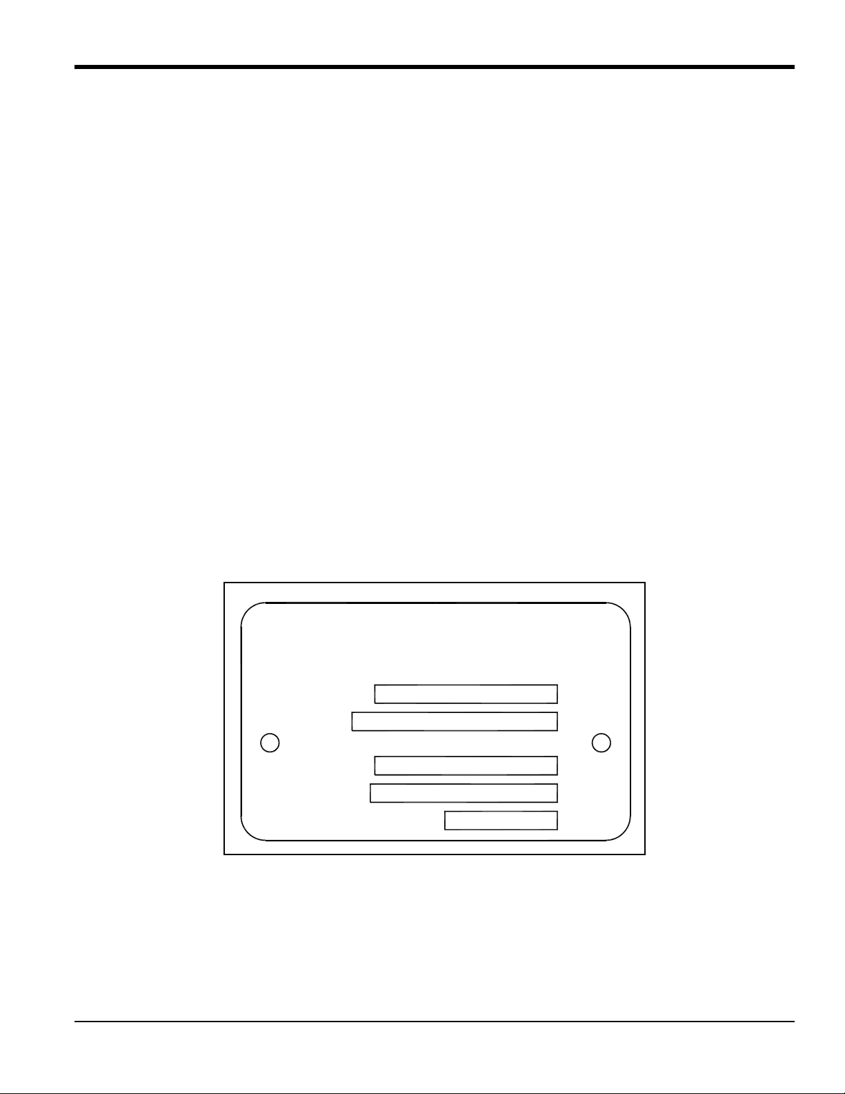
Locate the product label on your MMR31, and compare the last five characters of the model number with the product
numbering structure shown on the next page. This will confirm that your MMR31 has been configured to your
specifications. In the example shown in Figure 1 below, the characters R8A2A indicate: standar d certification (not
certified), G1/2 compression fitting (male thread) with gasket and SS ferrule, protective cap with standard
100 micron sintered filter, encl osure conduit M20 x 1.5-F with 1/2” NPT-F adapter and plug, and one selectable
4-20 mA output (RH 0-100% or dew point –15°C to +85°C, absolute humidity, mixing ratio, no display,
fault status 22 mA).
Figure 1: DewPro MMR31 Product Label
DewPro® MMR31 Installation & Operation Manual 1
Page 10

Chapter 1. General Information
1.2 Model Number (cont.)
MMR31 –
1 - Certification
R. Standard Certification (not certified)
S. Other
2 - Process Connection
1. 3” diameter galvanized floor flange with 12.7 mm (½” NPT-M) compression fitting
2. 3/4” NPT-M compression fitting
3. 1/2” NPT-M compression fitting
4. 3/4” x 16 “O” ring compression fitting (UNF thread)
6. No mounting hardware
8. G1/2 compression fitting (Male thread), gasket, SS ferrule
S. Other
12345
3 - Protective Cap
A. Standard, with 100 micron sintered filter
S. Other
4 - Enclosure Conduit
1. Enclosure Conduit M20 x 1.5-F with cable gland and plug
2. Enclosure Conduit M20 x 1.5-F with 1/2” FNPT adapter and plug
S. Other
5 - Output Configuration/Dewpoint Range
A. One output 4-20 mA selectable: RH 0-100% or dewpoi nt 15 to +85°C (5 to 185°F), absolute humidity,
mixing ratio, no display, fault status 22 mA
B. Two 4-20 mA DC output loops: 1st loop Moisture, 2nd loop temperature –15 to +85°C (5 to 185°F),
no display, fault status 22 mA
C. As A, fault status hold
D. As A, fault status 3.6 mA
E. As B, fault status hold
F. As B, fault status 3.6 mA
G. As A, with integral display, user interface
H. As B, with integral display, user interface
S. Other
2 DewPro® MMR31 Installation & Operation Manual
Page 11

Chapter 1. General Information
1.3 Version Descriptions
The DewPro MMR31 mid-range moisture transmitter is available in two versions:
• One isolated 4-20 mA current loop: The loop current represents the selected moisture unit (see “Selecting the
Units of Measure” on page 14).
• T wo isolat ed 4-20 mA loops: The second loop current represents temperature. A unique patented feature of this
version is that both loops can be powered by a single supply.
The MMR31 transmitter includes:
• Sensor element
• Stainless steel probe
• Weather-proof enclosure
• Microprocessor electronics
It is designed to be inserted directly into the process. Various mounting hardware, such as flange and compression
fittings are available for mounting into a duct, process chamber, wall, etc. The DewPro MMR31 measures relative
humidity in %, dew point temperature in °F or °C, absolute humidity in g/m
display with user interface allows the user to configure the MMR31 (see Chapter 4, “Optional Display/User Interface”
on page 19).
3
, or mixing ratio in g/kg. An optional
DewPro® MMR31 Installation & Operation Manual 3
Page 12

Chapter 1. General Information
1.4 Theory of Operation
1.4.1 First 4-20 mA Loop
The MMR31 microcontroller-operated electronics operates with a voltage supply of 12 to 28 VDC. At the nominal
24 VDC supply, the maximum loop resistance is 600 ohms. The signal is represented by the 4 to 20 mA loop current
and is directly proportional to 0 to 100% relative humidity, or, if selected, the dew point temperature range of
5 to 185°F (-15 to +85°C), the absolute humidity in a range of 1 to 350 g/m
1 to 830 g/kg.
1.4.2 Second 4–20 mA Loop
The specifications for the first loop current are also valid for the second loop current, except that the 4 to 20mA signal
always corresponds to the temperature range of 5 to 185°F (-15 to +85°C).
1.4.3 Polymer Sensor
The sensing element in the MMR31 is a silicon-based polymer that uses the capacitance principle for the moisture
measurement. The IC chip includes the moisture sensor and appropriate integrated circuitry. A platinum RTD
temperature sensor is built in to provide temperature compensation for maximum accuracy. The sensor element is
protected from condensation using a hydrophobic sintered filter. An additional removable filter cap serves as a
pre-filter.
3
, or the mixing ratio in a range of
1.4.4 Calibration
Each MMR31 is factory-calibrated against precise NIST certified moisture references. Field calibration is possible with
the use of saturated salt solutions (refer to Chapter 3, “Calibration and Troubleshooting” on page 15).
4 DewPro® MMR31 Installation & Operation Manual
Page 13
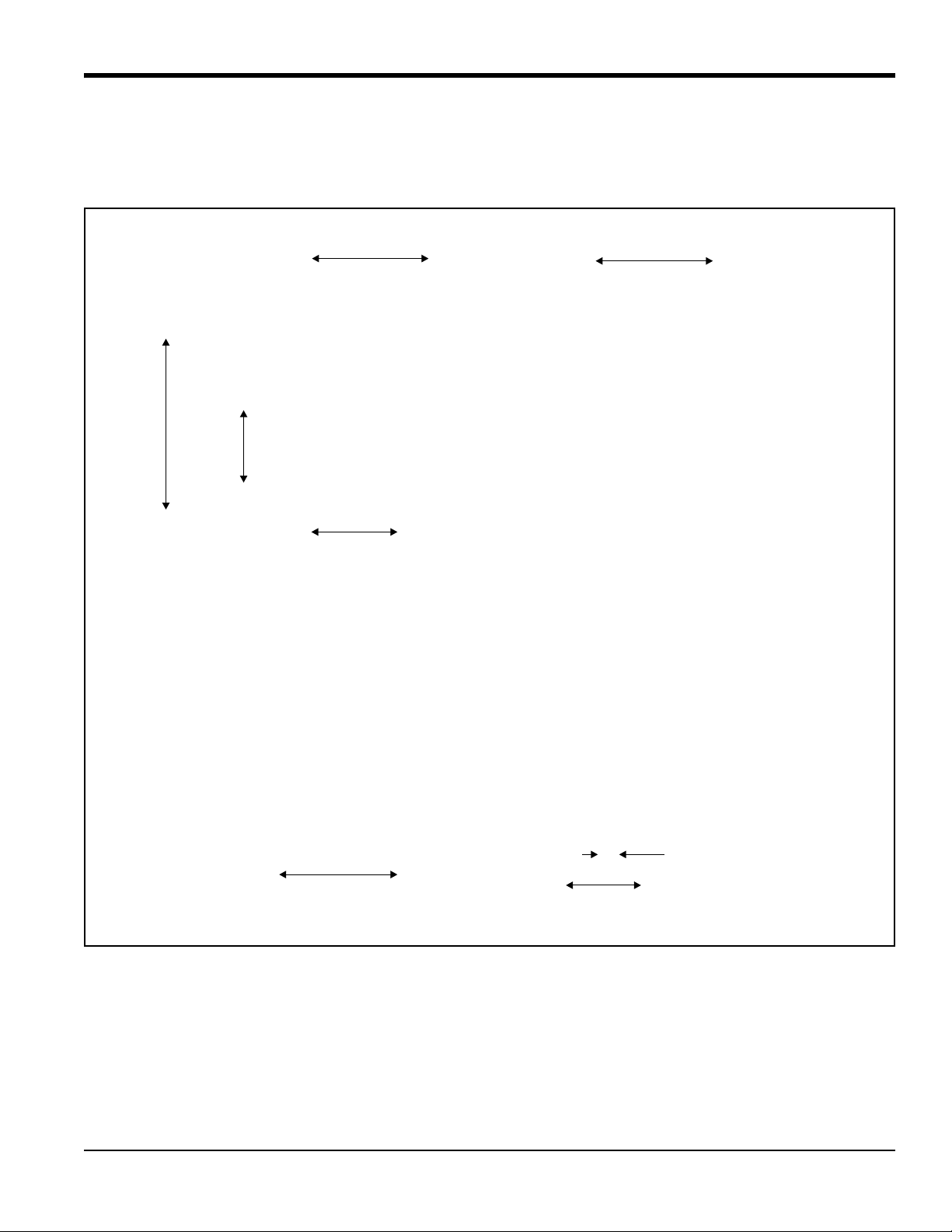
Chapter 2. Installation
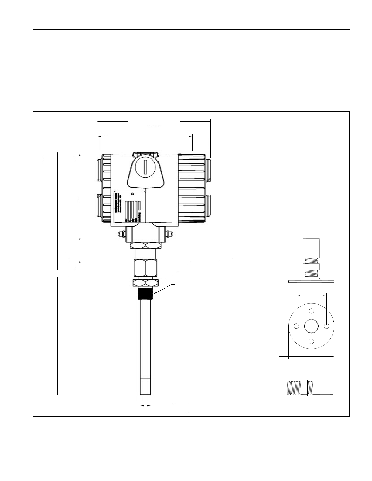
11.50 [292]
4.25 [108]
0.79 [20]
0.50 [12.7]
5.43 [138] (w/display)
4.49 [114] (wo/display)
NOTE: Dimensions are inches [mm]
Compression Fitting
2.00 [50.8]
Ø3.00 [76.2]
Thread
(G1/2, 1/2" NPT-M, etc.)
To properly install your MMR31, carefully follow the instructions in this chapter.
2.1 Mounting the MMR31
To select a suitable mounting location, refer to the dimensions shown in Figure 2 below.
Chapter 2. Installation
Figure 2: MMR31 and Compression Fitting Dimensions
DewPro® MMR31 Installation & Operation Manual 5
Page 14
Chapter 2. Installation
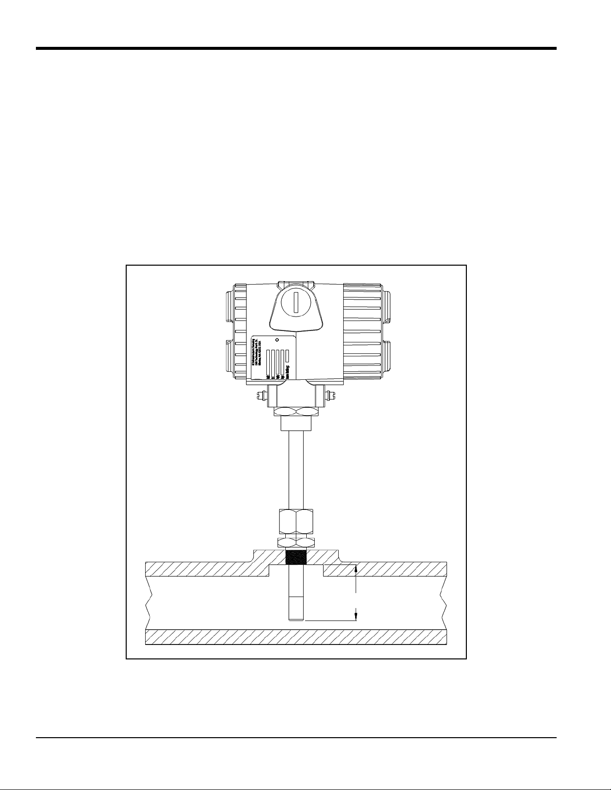
Min. 1 in. (25 mm)
2.1.1 Using a Compression Fitting or a Flange
IMPORTANT: Be certain that the tip of the probe does not touch the inside wall of the pipe or container.
IMPORTANT: A 1.4571 stainless steel ferrule is required for use in pressurized systems. Ensure that your probe has
the appropriate fitting for your application.
T o monitor moisture inside a pipe or container, mount the probe using a compression fitting connection or a flange (see
Figure 3 below). Adjust the ferrule for a probe insertion length of at least 1 in. (25 mm) and tighten the compression
fitting as follows:
1. Hand-tighten the nut.
2. Use a wrench to tighten the nut 1-1/2 turns. When tightened in this manner, the fitting with a stainless steel
ferrule can withstand pressures up to 17 bar (250 psi).
Figure 3: Mounting the Probe in a Pipe
6 DewPro® MMR31 Installation & Operation Manual
Page 15
Chapter 2. Installation
6.50 in.
(165 mm)
2.76 in.
(70 mm)
4.45 in.
(113 mm)
3.23 in.
(82 mm)
4.45 in.
(113 mm)
2.76 in.
(70 mm)
0.79 in.
(20 mm)
4.45 in.
(113 mm)
Panel Mounting
Vertical Pipe Mounting
Horizontal Pipe Mounting
Horizontal Pipe Mounting
2.1.2 Using a Bracket
The MMR31 can be used to monitor the air in a room or other such area, by using the available mounting kits shown in
Figure 4 below.
Figure 4: Mounting Kit Configurations
DewPro® MMR31 Installation & Operation Manual 7
Page 16

Chapter 2. Installation
Customer’s Power Supply
24 VDC (12-28 VDC)
Power Supply
(available from GE)
Power Supply with Display and Optional Relay
(available from GE)
115/230 VAC
115/230 VAC
2.2 Wiring Configurations with One Current Loop
CAUTION! The MMR31 system contains electronic components that are susceptible to damage by
static electricity. Proper handling procedures must be observed during the removal, installation, or
other handling of internal circuit boards.
2.2.1 General Guidelines
The maximum loop resistance is an important parameter for selection of the supply voltage, because each device
connected to the loop causes a voltage drop. For instance, using a loop-powered display with an input impedance of
50 ohms will cause a voltage drop of 1 VDC at 20 mA, per Ohm's law (V = R x I = 50 x 0.020 = 1). Similarly,
connecting the loop to a Programmable Logic Controller (PLC) will cause a voltage drop across its input.
When designing your loop, add up all voltage drops across the devices connected to the loop and then add 12 V. This
sum is the minimum supply voltage required for the circuit. T o ensure reliable operation, it is recommended that a 20%
safety factor be added to the calculated voltage requirement.
IMPORTANT: The voltage across the + and - terminals of the MMR31 should not fall below 12 VDC.
If an external display is used, configure it to the proper range: 0-100 % RH, 5 to 185°F (–15 to +85°C) dew point,
1 to 350 g/m
3
absolute humidity, 1 to 830 g/kg mixing ratio, or custom range corresponding to 4–20 mA. Figure 5
below illustrates some common system configuration options.
Figure 5: System Configuration Options
8 DewPro® MMR31 Installation & Operation Manual
Page 17

Chapter 2. Installation
External Earth Ground
Connect the cable shield
Shielded Two-Wire
Cap
Cable
to the ground terminal
for maximum RFI protection
2.2.2 Normal Environments
A standard two-wire, stranded cable can be used in a normal environment to interconnect the MMR31 with its loop
power source.
2.2.3 Environments with Severe Electrical Noise
When the MMR31 is installed in environments with severe electrical noise, wiring must be done with shielded and
grounded cable, as shown in Figure 6 below. Details of the MMR31 testing and certifications in such environments can
be found in Chapter 5, “Specifications” on page 29, and the CE Declaration of Conformity at the end of this manual.
Figure 6: Shielded Cable Wiring Diagram
DewPro® MMR31 Installation & Operation Manual 9
Page 18

Chapter 2. Installation
GND
LOOP 1
–+
+
–
24 VDC Nominal (12–28V)
External GND/SHIELD Connection
Internal GND Connection
2.2.4 General Wiring Instructions
To wire the MMR31, refer to Figure 7 below and complete the following steps:
1. Unscrew the cap on the terminal side of the unit.
2. Loosen the cable gland located on the side of the unit.
3. Feed the cable through the conduit opening.
Note: Use a standard signal cable size.
4. Retighten the metal cable gland to meet IP 67 and to relieve any stress on the wire.
5. Connect the wires to the MMR31 terminals as shown in Figure 7 below.
6. Verify that a voltage between 12 and 28 VDC is present across the terminals marked + and –.
Note: This is the voltage that is actually measured acr oss the MMR31 terminals. It is not necessarily exactly the same
as the power supply voltage, due to voltage loss in the wires, displays, indicators, etc.
7. To meet EMI/RFI immunity requirements, a two-wire shielded cable with a common foil shield layer is used to
power the MMR31. To clamp the shield foil in the metal cable gland, remove 3 in. (75 mm) of the insulation
and fold back the foil. The ground wire must be connected to the internal grounding screw.
Figure 7: Electrical Connections - One Current Loop
10 DewPro® MMR31 Installation & Operation Manual
Page 19

Chapter 2. Installation
115/230 VAC
115/230 VAC
2.3 Wiring Configurations with Two Current Loops
CAUTION! The MMR31 system contains electronic components that are susceptible to damage by
static electricity. Proper handling procedures must be observed during the removal, installation, or
other handling of internal circuit boards.
2.3.1 General Guidelines
The maximum loop resistance is an important parameter for selection of the supply voltage, because each device
connected to the loop causes a voltage drop. For instance, using a loop-powered display with an input impedance of
50 ohms will cause a voltage drop of 1 VDC at 20 mA, per Ohm's law (V = R x I = 50 x 0.020 = 1). Similarly,
connecting the loop to a Programmable Logic Controller (PLC) will cause a voltage drop across its input.
When designing your loop, add up all voltage drops across the devices connected to the loop and then add 12 V. This
sum is the minimum supply voltage required for the circuit. T o ensure reliable operation, it is recommended that a 20%
safety factor be added to the calculated voltage requirement.
IMPORTANT: The voltage across the + and - terminals of the MMR31 should not fall below 12 VDC.
If an external display is used, configure it to the proper range: 0-100 % RH, 5 to 185°F (–15 to +85°C) dew point,
1 to 350 g/m
3
absolute humidity, 1 to 830 g/kg mixing ratio, or custom range corresponding to 4–20 mA. Figure 8
below illustrates a typical configuration.
The same general specifications apply to the second current loop. However, the range for the second current loop is
always 5 to 185°F (–15 to +85°C), corresponding to temperature, unless an optional display/user interface is used for a
custom range.
IMPORTANT: Be sure that the two current loops are connected independently. DO NOT install a jumper at the
MMR31 + and - terminals to power both current loops from a single power supply.
Figure 8: System Configuration with Display and Power Supply
DewPro® MMR31 Installation & Operation Manual 11
Page 20

Chapter 2. Installation
External Earth Ground
Connect the cable shield
Shielded Four-Wire
Cap
Cable
to the ground terminal
for maximum RFI protection
2.3.2 Normal Environments
A standard two-wire, stranded cable can be used in a normal environment to interconnect the MMR31 with its loop
power sources.
2.3.3 Environments with Severe Electrical Noise
When the MMR31 is installed in environments with severe electrical noise, wiring must be done with shielded and
grounded cable, as shown in Figure 9 below. Details of the MMR31 testing and certifications in such environments can
be found in Chapter 5, “Specifications” on page 29, and the CE Declaration of Conformity at the end of this manual.
Figure 9: Shielded Cable Wiring Diagram
12 DewPro® MMR31 Installation & Operation Manual
Page 21

Chapter 2. Installation
GND
LOOP 1
–+
+
–
+
–
24 VDC Nominal (12–28V)
24 VDC Nominal (12–28V)
External GND/SHIELD Connection
Internal GND Connection
LOOP 2
+–
2.3.4 General Wiring Instructions
To wire the MMR31, refer to Figure 10 below and complete the following steps:
1. Unscrew the cap on the terminal side of the unit.
2. Loosen the cable gland located on the side of the unit.
3. Feed the cable through the conduit opening.
Note: Use a standard signal cable size.
4. Retighten the metal cable gland to meet IP 67 and to relieve any stress on the wire.
5. Connect the wires to the MMR31 terminals as shown in Figure 10 below.
6. Verify that a voltage between 12 and 28 VDC is present across the terminals marked + and –.
Note: This is the voltage that is actually measured acr oss the MMR31 terminals. It is not necessarily exactly the same
as the power supply voltage, due to voltage loss in the wires, displays, indicators, etc.
7. To meet EMI/RFI immunity requirements, a four-wire shielded cable with a common foil shield layer is used
to power the MMR31. T o clamp the shield foil in the metal cable gl and, remove 3 in. (75 mm) of the insulat ion
and fold back the foil. The ground wire must be connected to the internal grounding screw.
Figure 10: Electrical Connections - Two Current Loops
DewPro® MMR31 Installation & Operation Manual 13
Page 22

Chapter 2. Installation
0
5
1
2
3
4
6
7
8
9
S3
2.4 Selecting the Units of Measure
Unless otherwise specified, the MMR31 is shipped with a standard range of 0-100% relative humidity. To select other
units of measure, complete the following steps:
1. Remove the cover opposite to the wiring compartment to access Switch S3 (see Figure 11 below).
Figure 11: Switch S3 Location
2. Using a 2-mm screwdriver, turn Switch S3 to the position corresponding to your desired units of measure. The
available options are listed in Table 1 below:
Table 1: Units of Measure Options
Switch S3 Position Mode Range
0 % RH 0 to 100%
1 Dew point 5 to 185°F
(–15 to +85°C)
2 Mixing Ratio 1 to 830 g/kg
3 Absolute Humidity
1 to 350 g/m
3
8 Dew point Custom
9
with Salt Bottles (75.4 and 11.3%)
% RH Calibration
0 to 100%
For example, if Switch S3 is set to position 1 to select dew point mode, the current output represents a 5 to 185°F
(–15 to +85°C) dew point temperature range. Any attached indicators need to be rescaled from their original
RH (0–100%) range to the new dew point range.
14 DewPro® MMR31 Installation & Operation Manual
Page 23

Chapter 3. Calibration and Troubleshooting
Chapter 3. Calibration and Troubleshooting
3.1 Calibration Using Two Saturated Salt Solutions
CAUTION! Be certain that the system is depressurized. The MMR31 must be removed from the
process prior to calibration.
Utilizing saturated salt solutions is one of many methods available to calibrate a relative humidity sensor. Depending
on the salt used (lithium chloride and sodium chloride are recommended), a defined relative humidity will occur above
the solution at a given temperature. The accuracy of this method is dependent on the stability of the temperature during
the calibration. It is important that the temperature of the salt solution and the temperature of the enclosed atmosphere
above the solution are the same.
Note: To achieve optimum results, it is recommended that calibration be performed at 77.5°F (25.3°C) because the
temperature compensation correction is zero at this temperature. Deviating from this value by ±9°F (±5°C)
will introduce an error of approximately 1%.
To complete the following procedure, you will need:
• Two salt calibration bottles (11.3% and 75.4%) of the type available from GE for RH field calibration
• Screwdriver, 2-mm wide
• An ammeter or current display with a range of 0-100 mA
DewPro® MMR31 Installation & Operation Manual 15
Page 24

Chapter 3. Calibration and Troubleshooting
0
5
1
2
3
4
6
7
8
9
S3
3.2 Calibration Steps
Note: The following steps describe the use of an ammeter for calibration. If the current loop already contains a
current display to indicate the moisture values, an additional ammeter is unnecessary.
1. Remove both covers from the MMR31 enclosure.
2. Disconnect the negative (–) lead of moisture loop 1.
3. Connect the ammeter into the loop as shown in Figure 12 below.
4. Choose the 20 mA range on the ammeter.
Figure 12: Ammeter Connections
T wo buttons (S1 an d S2) and one rotary switch (S3) are located on the circuit board. Button S1 is used to calibrate the
11.3% RH value with a lithium chloride salt solution, while button S2 is used to calibrate the 75.4% RH value with a
sodium chloride salt solution. Switch S3 is set to position 9 for calibration mode (see Figure 13 below).
Note: If the unit is equipped with a display, the buttons on the display are used instead (see Chapter 4, “Optional
Display/User Interface” on page 19 for detailed instructions).
5. Use a 2-mm screwdriver to turn Switch 3 to position 9.
16 DewPro® MMR31 Installation & Operation Manual
Figure 13: Setting Switch S3
Page 25

Chapter 3. Calibration and Troubleshooting
3.2.1 Calibrating the Low RH Reading
Note: For the low RH reading, a saturated salt solution of lithium chloride is used to provide an 11.3% relative
humidity reference.
1. Insert the probe into the calibration bottle, almost to the bottom.
2. Observe the ammeter. The reading will change toward 5.8 mA (or 11.3% on a display) after insertion of the
probe.
Note: For successful calibration, it is important that the temperature in the salt solution and in the enclosed
atmosphere above the solution r each equilibrium at the same value. After waiting for appr oximately two hours,
the ammeter reading should stabilize.
3. If the meter reading is stable at 5.80 mA (or 11.3% on a display), press Sl for at least one second. This assigns
the 11.3% RH value. If only the low RH calibration will be performed, return Switch S3 to position 0 (see
Figure 13 on page 16). Otherwise, continue to the next section to calibrate the high RH reading.
3.2.2 Calibrating the High RH Reading
Note: For the high RH reading, a saturated salt solution of sodium chloride is used to provide an 75.4% relative
humidity reference.
1. Insert the probe into the calibration bottle, almost to the bottom.
2. Observe the ammeter. The reading will change toward 16 mA (or 75.4% on a display) after insertion of the
probe.
Note: For successful calibration, it is important that the temperature in the salt solution and in the enclosed
atmosphere above the solution r each equilibrium at the same value. After waiting for appr oximately two hours,
the ammeter reading should stabilize.
3. If the meter reading is stable at 16 mA (or 75.4% on a display), press S2 for at least one second. This assigns
the 75.4% RH value. Return Switch S3 to position 0 (see Figure 13 on page 16).
4. After successful calibration, remove the ammeter, reconnect the negative (-) lead and reinstall the cover.
Note: During calibration, if the wrong key is pressed, the value will not be accepted due to a plausibility check
DewPro® MMR31 Installation & Operation Manual 17
Page 26

Chapter 3. Calibration and Troubleshooting
3.3 Troubleshooting
3.3.1 Loop Current is Out of Range
3.3.1a Unit of Measure is RH
Note: 0% and 100% relative humidity are absolute limits. However , a defective sensor or a malf unction of th e sensor
electronics could generate sensor signal values which are outside the 0-100% range. If the sensor signal value
is above 100% or below 0%, the current will go to the fault current specified on the order or in the matrix field
VH 07.
Solution: Expose the sensor to ambient air which normally has a relative humidity between 10% and 90%. If the
current returns the 4–20 mA range, check the sensor calibration (see “Calibration St eps” on page 16). However, if the
current remains in error mode contact GE for assistance.
3.3.1b Unit of Measure is Dew Point
Solution 1: The process dew point is out of range. If the dew point is above 185°F (85°C), the current will go to the
fault current specified on the order or in the matrix field VH 07. Apply dry air for a few minutes. If the current remains
in error mode contact GE for assistance.
Solution 2: If the dew point is below 5°F (–15°C), the current will go to the fault current specified on the order or in the
matrix field VH 07. Move the sensor into a wetter environment for a few minutes. If the dew point doesn't increase, the
cause may be a defective sensor assembly or an electronics malfunction. Contact GE for assistance.
Note: The same approach is valid for the other available units of measure and for the second loop (temperature).
3.3.2 No Loop Current
Solution: Check the voltage and polarity across the positive (+) and negative (-) terminals of the MMR31 with a DC
voltmeter. If the voltage is within the 12-28 VDC range, contact GE for assistance.
3.3.3 Slow Response Time
Solution: Remove the protective filter cap by turning it counter -clockwise, and clean it with air flow or a solvent. If the
sensor filter is contaminated, clean it with hot water using a brush.
3.3.4 Frozen Output Current
Solution: Check Switch S3, which should be in position 0, 1, 2, 3, 8 or 9.
18 DewPro® MMR31 Installation & Operation Manual
Page 27

Chapter 4. Optional Display/User Interface
S
e
n
si
n
g
Chapter 4. Optional Display/User Interface
4.1 Accessing the Programming Buttons
If your MMR31 is equipped with an optional display/user interface, follow the procedure below to access the
programming buttons.
4.1.1 Removing the Display
To remove the display/user interface, refer to Figure 14 below and complete the following steps:
1. Unscrew and remove th e pro t ectiv e co ver from th e t op of the MMR31, exposing the display module. The four
buttons V, H, + and – are now accessible.
2. The display un it snaps on to the prin ted circu it bo ard an d rests on fou r posts. When removing th e d i sp lay, push
one post to the outside, using a small screwdriver, and pull the display out.
3. Then, unplug the display cable.
Figure 14: MMR31 with Display
DewPro® MMR31 Installation & Operation Manual 19
Page 28

Chapter 4. Optional Display/User Interface
H
V
+
–
DewPro
4.2 Programming the Matrix
In the MMR31 with the display option, a matrix-style input is used for programming the units of measure, measuring
range, error status of output, and output adjustment.
Note: For users of other GE Sensing equipment, this matrix format may be familiar. However, this section describes
the features and usage of the various matrix locations only as they apply to the MMR31.
The MMR31 display (see Figure 15 below) continuously shows the current matrix location using the vertical (V) and
horizontal (H) coordinates to designate the row and column, respectively. The bar graph represents the output current in
an analog fashion.
Figure 15: MMR31 Display
The V and H buttons are used to move to another row or column in the matrix (see Table 3 on page 21). For example, to
select location VH 45 from a starting location of VH 00, press V four times and then press H five times to arrive at
VH 45 (i.e., row 4 and column 5).
At any matrix location where the matrix value may be changed by the user, the digit to be changed is flashing, and the
desired value is programmed using the + and – buttons. For example, at matrix location VH 01, the desired moisture
units are selected by choosing from the matrix values listed in Table 2 below.
Table 2: Moisture Unit Options
Matrix Moisture Unit
0% RH
1 Td °C
2Td °F
3
20 DewPro® MMR31 Installation & Operation Manual
4g/kg
g/m
3
Page 29

Chapter 4. Optional Display/User Interface
Table 3: Matrix Options
MMR31RowH0H1H2H3H4H5H6H7H8H9
Moisture
Unit
V0
Display
Moisture
Value
Select
Moisture
Unit (see
Table 2)
Loop 1
at Fault
0 = –10%
1 = 110%
2 = Hold
Loop 1 Raw
Reading
Loop Range
V1
% RH
4 mA
% RH
20 mA
Dewpoint
°C
4 mA
Dewpoint
°C
20 mA
Dewpoint
°F
4 mA
Dewpoint
°F
20 mA
g/m
3
4 mA
g/m
3
20 mA
g/kg
4 mA
g/kg
20 mA
V2
Constant;
Loop
Hardware
Calibration
V3
Pressure
Constant in
mmHg
Loop 1 D/A
Calibration
Low
Loop 1 D/A
Calibration
High
T emp. Unit;
Loop 1
Hardware
Calibration
V4
Display
Temp. Value
Select Unit
of Temp.
0 = °C;
1 = °F
Temp.
4 mA
Temp.
20 mA
Loop 2
at Fault
0 = –10%
1 =110%
2 = Hold
Loop 2 Raw
Reading
V5
RH
Calibration
V6
Enable
Calibration;
enter digit
other than 0
Enter Low
RH (%)
Enter High
RH (%)
Loop 2
Hardware
Calibration
V7
Loop 2 D/A
Calibration
Low
Loop 2 D/A
Calibration
High
Access Key
V8
Input
Locking
50 = Unlock
Misc. Setup
V9
Display
Present
Error
Previous
Error
Unit ID Software
Version
Reset to
Defaults
50 =Reset
System
Reset
50 = Reset
DewPro® MMR31 Installation & Operation Manual 21
Page 30

Chapter 4. Optional Display/User Interface
4.3 Matrix Buttons - Special Functions
4.3.1 Reset to “Normal” Display
Pressing the V and H buttons simultaneously returns the user to VH 00 (normal display).
4.3.2 Display Only
Eight (8) matrix locations are for display only and may not be changed by the user (see Table 3 on page 21). The
“display only” fields are as follows:
Table 4: “Display Only” Matrix Locations
Location Display Description
VH 00 Normal display (in dewpoint, % RH, mixing ratio or absolute humidity
as selected in VH 01)
VH 08 Indicates digitized moisture signal
VH 40 Displays temperature
VH 48 Indicates digitized temperature signal
VH 90 During a system alarm, displays the error code for the fault encountered
VH 91 During normal operation, displays the previous error code for reference
VH 92 Displays the factory issued identification number
VH 93 Displays the factory-issued reference number designating the device type
and software version
4.3.3 Default Values
A default value is assigned to each programmable matrix field. These values are loaded after a reset to factory
programmed data has been executed (see VH 95).
4.4 Matrix Functions
This section describes the functions available to the user through the matrix, grouped by common function areas (see
Table 3 on page 21). Each function is accessed by moving to its specified location within the matrix.
22 DewPro® MMR31 Installation & Operation Manual
Page 31

Chapter 4. Optional Display/User Interface
4.4.1 System Administration Functions
Table 5: System Administration Functions
Function Location Description
Locking/
Unlocking
the Matrix
System Reset VH 99 This location allows the user to reset the system electronics in a manner similar to
VH 89 This location allows the user to lock and unlock the matrix input functions. When the
matrix is locked, the V and H keys are still functional but the + and – keys are disabled.
This prevents unauthorized modification of any of the user input functions, such as output
ranging or units selection. Entering the value 50 in this location unlocks the matrix. Any
other value locks the matrix. (Default: 0)
removing and re-applying power. No system parameter settings are modified. Entering
the value 50 in this location initiates the reset, and after approximately five (5) seconds
the reset is executed. After the reset, normal operation is resumed at location VH 00.
Transmitter
Identification
Software
Version
Two-Point
Calibration
Using Any
Low and High
RH Value
Low RH Point
Calibration
High RH Point
Calibration
VH 92 This location displays the identification number of the transmitter. The display should
read 200.
VH93 This location displays the version number of the instrument software.
VH67 In this location, the calibration using VH 68 and VH 69 is enabled by entering any digit
other than 0. Follow the steps described in “Calibration Steps” on page 16. Enter 11.3 in
VH 68 and 75.4 in VH 69.
If a different moisture source is being used (e.g., a variable moisture generator or other
saturated salt solutions), any low value can be entered in VH 68 and any high value in VH
69. Be sure the high and low values differ by at least 20%.
The hardware buttons on the printed circuit board are still active, performing an 11.3 and
75.4 calibration. As described in “Calibration Steps” on page 16, location VH 68 would
reset to 11.3 and location VH 69 to 75.4.
VH68 Enter the low RH value in % when the reading is stable. VH 67 has
to have a value other
than 0. Be sure the high and low values differ by at least 20%.
VH 69 Enter the high RH value in % when reading is stable. VH 67 has to have a value other
than 0. Be sure the high and low values differ by at least 20%.
DewPro® MMR31 Installation & Operation Manual 23
Page 32

Chapter 4. Optional Display/User Interface
4.4.2 Moisture Measurement Functions
Table 6: Moisture Measurement Functions
Function Location Description
Display
Current
Process Value
Select Units of
Measure for
Display
VH 00 This location displays the current process humidity value measured by the instrument.
The units of measure for the displayed value (i.e., % RH, dew point or units selected
under VH 01) is selected in position VH 01. The bar graph beneath the numeric display
represents the position of the current value within the range programmed for the selected
units of measure.
VH 01 This location selects the units of measure to be used for the humidity value display. The
available options are :
0 = % relative humidity (Default)
1 = °C dew point
2 = °F dew point
3 = grams/m
3
4 = grams/kg dry air.
Loop #1
at Fault
Display the
Moisture
Frequency
VH 07 This location specifies the state of current output #1, corresponding to the detection of a
fault with either the humidity sensor or the measurement circuitry. The available options
are:
0 = –10% (3.6 mA)
1 = 110% (22 mA) (Default)
2 = Hold at previous level
VH 08 When this location is selected, the A/D counts from the moisture measurement circuit are
displayed.
24 DewPro® MMR31 Installation & Operation Manual
Page 33

4.4.3 4-20 mA Output Range Functions
Table 7: Setting Output Ranges for Humidity 4-20mA Output
Function Location Description
Range of
Humidity
Values
Pressure
Constant
Adjustment
VH 10 % RH 4mA (Default: 0)
VH 11 % RH 20mA (Default: 100)
VH 12 °C dew point 4mA (Default: –15)
VH13 °C dew point 20mA (Default: +85)
VH 14 °F dew point 4mA (Default: 5)
VH 15 °F dew point 20mA (Default: 185)
VH 16
VH 17
grams/m
grams/m
3
4mA (Default: 1)
3
20mA (Default: 350)
VH 18 grams/kg dry air 4mA (Default: 1)
VH 19 grams/kg dry air 20mA (Default: 830)
VH 30 This location allows the user to enter a value for the process pressure. The value is
entered in mmHg. This value is used only for the calculation of the unit grams/kg dry air.
(Default: 760)
Chapter 4. Optional Display/User Interface
Calibrating the
Current Output
VH 38
VH 39
These locations are used to calibrate the 4 mA and 20 mA hardware settings of the
humidity output current loop. This output comes calibrated from the factory and should
not normally need adjustment. To check the setting, connect an ammeter in series with
the negative (–) power terminal for loop #1 (see “Wiring Configurations with One
Current Loop” on p age 8). Move to matrix location VH 38. The output will automatically
change to the 4 mA setting. Adjust as necessary using the + and – keys. Move to location
VH 39. The output will automatically change to the 20 mA setting. Adjust as necessary.
Move to any other matrix location to return the output to normal operation.
If the matrix input is locked (VH 89), the calibration values are displayed, but the current
output is unaffected.
DewPro® MMR31 Installation & Operation Manual 25
Page 34

Chapter 4. Optional Display/User Interface
4.4.4 Temperature Measurement Functions
Table 8: Temperature Measurement Functions
Function Location Description
Displaying the
Measured
Temperature
Selecting the
Temperature
Unit
VH 40 Selecting this location displays the present process temperature. The unit of measure
(°F/°C) is the unit selected in location VH41 (see below).
VH 41 This allows the user to select either °F or °C as the temperature measurement unit to be
displayed in location VH 40. Setting this location to 0 selects °C, and setting to 1
selects °F. (Default: 0)
Setting the
Temperature
Output Range
Loop #2
at Fault
Calibrating the
Current Output
VH 45
VH 46
These locations specify the range of temperatures corresponding to the 4–20 mA range of
current output #2. The range of values for both locations is from –15 and +85. The output
range is always specified in °C, regardless of the display units selected.
VH 47 This location specifies the condition for current output #2 when a fault is detected in the
temperature measurement circuitry. The available options are:
0 = –10% (3.6 mA)
1 = 110% (22 mA) (Default)
2 = Hold at previous level
VH 78
VH 79
These locations are used to calibrate the 4 mA and 20 mA hardware settings of the
temperature output current loop. This output comes calibrated from the factory and
should not normally need adjustment. To check the setting, connect an ammeter in series
with the negative (–) power terminal for loop #2. Move to matrix location VH 78. The
output will automatically change to the 4 mA setting. Adjust as necessary using the + and
– keys. Move to location VH 79. The output will automatically change to the 20 mA
setting. Again, adjust as necessary. Move to any other matrix location to return the output
to normal operation.
If the matrix input is locked (VH 89), the calibration values are displayed, but the current
output is unaffected.
26 DewPro® MMR31 Installation & Operation Manual
Page 35

Chapter 4. Optional Display/User Interface
4.4.5 Error Codes
During normal MMR31 operation, it is possible for the temperature channel to be in error, while the RH channel still
reads correctly. It is also possible for the RH channel to be in error, while the temperature channel still reads correctly.
If a moisture unit that depends on both the RH and temperature values (e.g., dewpoint) is selected, the error conditions
for both RH < 0% and RH > 100% will be set. MMR31 errors are indicated in the matrix (see Table 3 on page 21), as
shown in Table 9 below.
Table 9: Error Code Display
Function Location Description
Display the
Present
Error Code
The procedure for interpreting the VH 90 error codes involves the conversion of numbers from decimal format into
binary format. To perform these conversions, refer to Table 10 below.
VH 90 This location displays a number associated with an error code. If no error condition
exists, the location displays 0. Use the instructions in this section to properly interpret the
error code.
Table 10: Decimal to Binary Conversions
Decimal Value Binary Equivalent
0 0000
1 0001
2 0010
30011
4 0100
5 0101
60110
7 0111
8 1000
9 1001
10 1010
11 1011
12 1100
13 1101
14 1110
15 1111
DewPro® MMR31 Installation & Operation Manual 27
Page 36

Chapter 4. Optional Display/User Interface
4.4.5 Error Codes (cont.)
When a value other than 0 is displayed in matrix location VH 90, complete the following steps to determine the cause of
the error (a value of 39 is used as an example in the steps below):
1. Divide the error code displayed in matrix location VH 90 by 16.
[Example: 39/16 = 2.4375]
2. Determine the temperature channel error code by converting the integer portion of the result in step 1 to binary
format (see Table 10 on page 27).
[Example: integer portion of 2.4375 = 2 = 0010 binary]
3. Determine the moisture channel error code by multiplying the decimal portion of the result in step 1 by 16 and
then converting the result to binary format (see Table 10 on page 27).
[Example: 16 x decimal portion of 2.4375 = 16 x 0.4375 = 7 = 0111 binary]
4. Each “1” in the binary values calculated in steps 2 and 3 above corresponds to a particular MMR31 error.
Identify these errors by referring to Table 11 below.
[Example: The “1” in the third position of the temperatur e channel error code (see step 2 above) means that the
temperature reading is > 85°C. The “1” in the second, third and fourth positions of the moisture channel error
code (see step 3 above) means that Output 1 is < 4 mA and that the moisture unit selected depends on the
temperature.
Table 11: Error Code Identifications
Temperature Channel 4-Digit Code Moisture Channel 4-Digit Code
XXXX XXX*X*
CH2 Output
> 20 mA
CH2 Output
< 4 mA
Temp.
> +85°C
Temp.
< -15°C
CH1 Output
> 20 mA
CH1 Output
< 4
mA
RH
> 100%
RH
< 0%
* If both of these positions are set to “1”, the selected moisture unit depends on the temperature.
To further illustrate the process, let’s try one more example. If the VH 90 matrix location displays an error code of 1:
Step 1: 1/16 = 0.0625
Step 2: temperature channel error code = integer portion of 0.0625 = 0 = 0000 binary
Step 3: moisture channel error code = 16 x decimal portion of 0.0625 = 16 x 0.0625 = 1 = 0001 binary
Step 4: There are no temperature errors. The moisture error indicates that RH < 0%
28 DewPro® MMR31 Installation & Operation Manual
Page 37

Chapter 5. Specifications
5.1 Technical Specifications
Sensing Element:
Silicon-based polymer, capacitance principle, IC electronics
RH Range:
0 to 100%
RH Accuracy:
±2% in the range of 0% to 90% at 25°C
±3% in the range of 90% to 100% at 25°C
Dew Point Range:
5 to 185°F (–15 to +85°C)
Chapter 5. Specifications
Dew Point Accuracy:
±1.8°F (±1°C) above 32°F (0°C), T <86°F (<30°C) and RH >30%
Operating Temperature Range:
5 to 185°F (–15 to +85°C); temperature signal available with second loop
Operating Temperature of Electronics:
–40 to +185°F (–40 to +85°C)
Temperature Accuracy:
±0.9°F (±0.5°C)
Absolute Humidity Range:
1 to 350 g/m
Mixing Ratio Range:
1 to 830 g/kg
3
Maximum Operating Pressure:
250 psig (17 bar)
Outputs:
Loop current 4 to 20 mA, 16 µA resolution, optional output for temperature
DewPro® MMR31 Installation & Operation Manual 29
Page 38

Chapter 5. Specifications
5.1 Technical Specifications (cont.)
Electronics:
Microcontroller operation
EM I/RFI Protection:
See “EMI/RFI Protection” on page 31
Moisture Units:
% RH, dew point temperature in °F or °C, absolute humidity in g/m
Power Supply:
24 VDC nominal, 12 to 28 VDC range
Protection:
Type 4X (IP67)
3
, or mixing ratio in g/kg, hardware selectable
Probe Tube:
316 stainless steel, 1/2 in. (12.7 mm) diameter, insertion length 3.0 in. (75 mm) to 5.9 in. (150 mm), adjustable
Typical Probe Mounting:
1/2 in. (12.7 mm) tube x 1/2 in. (12.7 mm) NPT-M or
1/2 in. (12.7 mm) tube x G 1/2 compression fitting.
Weight:
3.3 lb (1.5 kg)
5.2 Optional Onboard Display with User Interface
The optional onboard display with user interface uses a matrix configurator for:
• Range changes
• Unit of measure selection
• Current loop adjustment
• Error diagnostics
• Current value selection for fault conditions
• Entering a pressure constant for ppm
30 DewPro® MMR31 Installation & Operation Manual
v
Page 39

Chapter 5. Specifications
5.3 EMI/RFI Protection
IEC 61000-4, Performance Criterion A test results for the MMR31 were as follows:
• Conducted Emission Test as per CISPR 11 Class A, 2004
• Radiated Emission Test as per CISPR 11 Class A, 2004
• Radiated Susceptibility Test as per IEC 61000-4-3, 2002
• Electrostatic Discharge Test as per IEC 61000-4-2, 2001
• Electrical Fast Transient Test as per IEC 61000-4-4, 2004
• High Energy Surge Immunity Test as per IEC 61000-4-5, 2001
• Power Frequency Magnetic Field Test as per IEC 61000-4-8, 2001
5.4 EMC Compliance
The MMR31 meets the EMC requirements of IEC 61326 for equipment used in industrial locations
5.5 Available Accessories
The following optional accessories are available for the MMR31:
• Single power supply
• Panel mount display, power supply, no relays
• Panel mount display, power supply, two alarms
• Panel mount display, power supply, two alarms, 4-20 mA repeating output
Note: For other requirements, contact GE for assistance.
DewPro® MMR31 Installation & Operation Manual 31
Page 40

Chapter 5. Specifications
[no content intended for this page]
32 DewPro® MMR31 Installation & Operation Manual
Page 41

Index
A
Accessories, Available . . . . . . . . . . . . . . . . . . . . . . . 31
Ammeter, Calibration . . . . . . . . . . . . . . . . . . . . . . . 15
B
Binary Conversion Table . . . . . . . . . . . . . . . . . . . . . 27
Bracket, Mounting with . . . . . . . . . . . . . . . . . . . . . . . 7
Buttons
Calibration
Matrix Programming . . . . . . . . . . . . . . . . . . . . . . 20
Programming, Accessing . . . . . . . . . . . . . . . . . . . 19
Special Functions. . . . . . . . . . . . . . . . . . . . . . . . . 22
. . . . . . . . . . . . . . . . . . . . . . . . . . . . . 16
C
Cable, Shielded . . . . . . . . . . . . . . . . . . . . . . . . . . . . . 9
Calibration
Ammeter
Buttons . . . . . . . . . . . . . . . . . . . . . . . . . . . . . . . . 16
High RH Reading . . . . . . . . . . . . . . . . . . . . . . . . 17
Low RH Reading. . . . . . . . . . . . . . . . . . . . . . . . . 17
NIST Reference. . . . . . . . . . . . . . . . . . . . . . . . . . . 4
Steps Required. . . . . . . . . . . . . . . . . . . . . . . . . . . 16
Switch. . . . . . . . . . . . . . . . . . . . . . . . . . . . . . . . . 16
Using Saturated Salt Solutions . . . . . . . . . . . . . . . 15
Components, Transmitter. . . . . . . . . . . . . . . . . . . . . . 3
Compression Fitting, Mounting with. . . . . . . . . . . . . . 6
Conversion, Decimal to Binary Table . . . . . . . . . . . . 27
. . . . . . . . . . . . . . . . . . . . . . . . . . . . . . . 15
D
Date of Publication . . . . . . . . . . . . . . . . . . . . . . . . . . i
Default Values, Matrix. . . . . . . . . . . . . . . . . . . . . . . 22
Dimensions, Mounting. . . . . . . . . . . . . . . . . . . . . . . . 5
Display
Matrix Locations
Removing . . . . . . . . . . . . . . . . . . . . . . . . . . . . . . 19
Display/User Interface
Programming Buttons
Specifications . . . . . . . . . . . . . . . . . . . . . . . . . . . 30
Document Number . . . . . . . . . . . . . . . . . . . . . . . . . . i
. . . . . . . . . . . . . . . . . . . . . . . . . 22
. . . . . . . . . . . . . . . . . . . . . 20
E
Electrical Connections
One Current Loop
Two Current Loops . . . . . . . . . . . . . . . . . . . . . . . 13
Electrical Noise. . . . . . . . . . . . . . . . . . . . . . . . . . 9, 12
EMC Compliance . . . . . . . . . . . . . . . . . . . . . . . . . . 31
EMI/RFI Protection. . . . . . . . . . . . . . . . . . . . . . . . . 31
. . . . . . . . . . . . . . . . . . . . . . . . 10
Environmental Compliance . . . . . . . . . . . . . . . . . . . iv
Error Codes
Examples
Interpreting . . . . . . . . . . . . . . . . . . . . . . . . . . . . . 28
Matrix Location. . . . . . . . . . . . . . . . . . . . . . . . . . 27
Examples, Error Codes . . . . . . . . . . . . . . . . . . . . . . 28
. . . . . . . . . . . . . . . . . . . . . . . . . . . . . . 28
F
Flange, Mounting with. . . . . . . . . . . . . . . . . . . . . . . . 6
Functions
4-20 mA Output Range
Matrix. . . . . . . . . . . . . . . . . . . . . . . . . . . . . . . . . 22
Moisture Measurement. . . . . . . . . . . . . . . . . . . . . 24
System Administration. . . . . . . . . . . . . . . . . . . . . 23
Temperature Measurement . . . . . . . . . . . . . . . . . . 26
. . . . . . . . . . . . . . . . . . . . 25
G
Guidelines, Wiring . . . . . . . . . . . . . . . . . . . . . . . 8, 11
I
Information Paragraphs . . . . . . . . . . . . . . . . . . . . . . iii
Installation
Compression Fitting
Flange. . . . . . . . . . . . . . . . . . . . . . . . . . . . . . . . . . 6
In Pipe or Container. . . . . . . . . . . . . . . . . . . . . . . . 6
In Room . . . . . . . . . . . . . . . . . . . . . . . . . . . . . . . . 7
Mounting Dimensions . . . . . . . . . . . . . . . . . . . . . . 5
With Bracket . . . . . . . . . . . . . . . . . . . . . . . . . . . . . 7
. . . . . . . . . . . . . . . . . . . . . . . . 6
L
Label, Product. . . . . . . . . . . . . . . . . . . . . . . . . . . . . . 1
Loop
Current Out of Range
First, Description . . . . . . . . . . . . . . . . . . . . . . . . . . 4
Frozen Output Current . . . . . . . . . . . . . . . . . . . . . 18
No Current . . . . . . . . . . . . . . . . . . . . . . . . . . . . . 18
One, Electrical Connections . . . . . . . . . . . . . . . . . 10
Second, Description. . . . . . . . . . . . . . . . . . . . . . . . 4
Two, Electrical Connections . . . . . . . . . . . . . . . . . 13
Wiring. . . . . . . . . . . . . . . . . . . . . . . . . . . . . . . 8, 11
. . . . . . . . . . . . . . . . . . . . . . 18
DewPro® MMR31 Installation & Operation Manual 33
Page 42

Index
M
Matrix
"Display Only" Locations
4-20 mA Output Range Functions. . . . . . . . . . . . . 25
Default Values . . . . . . . . . . . . . . . . . . . . . . . . . . . 22
Error Codes. . . . . . . . . . . . . . . . . . . . . . . . . . . . . 27
Functions . . . . . . . . . . . . . . . . . . . . . . . . . . . . . . 22
Moisture Measurement Functions . . . . . . . . . . . . . 24
Programming. . . . . . . . . . . . . . . . . . . . . . . . . . . . 20
System Administration Functions . . . . . . . . . . . . . 23
Table of Options . . . . . . . . . . . . . . . . . . . . . . . . . 21
Temperature Measurement Functions . . . . . . . . . . 26
Model Number . . . . . . . . . . . . . . . . . . . . . . . . . . . 1, 2
Moisture Units, List of Options . . . . . . . . . . . . . . . . 20
Mounting Dimensions . . . . . . . . . . . . . . . . . . . . . . . . 5
. . . . . . . . . . . . . . . . . . . 22
N
NIST, Calibration Reference. . . . . . . . . . . . . . . . . . . . 4
Noise, Electrical . . . . . . . . . . . . . . . . . . . . . . . . . 9, 12
Normal Environments, Wiring . . . . . . . . . . . . . . . 9, 12
O
Operation, Theory . . . . . . . . . . . . . . . . . . . . . . . . . . . 4
Options, Available. . . . . . . . . . . . . . . . . . . . . . . . . . 31
P
Pipe, Mounting in . . . . . . . . . . . . . . . . . . . . . . . . . . . 6
Power Supply, Specifications . . . . . . . . . . . . . . . . . . 30
Product Label . . . . . . . . . . . . . . . . . . . . . . . . . . . . . . 1
Programming
Buttons
Matrix. . . . . . . . . . . . . . . . . . . . . . . . . . . . . . . . . 20
Programming Buttons, Accessing . . . . . . . . . . . . . . . 19
. . . . . . . . . . . . . . . . . . . . . . . . . . . . . . . . 20
R
Removing the Display . . . . . . . . . . . . . . . . . . . . . . . 19
Response Time, Slow. . . . . . . . . . . . . . . . . . . . . . . . 18
Return Policy . . . . . . . . . . . . . . . . . . . . . . . . . . . . . 35
RH
Calibrating High Reading
Calibrating Low Reading . . . . . . . . . . . . . . . . . . . 17
Room, Mounting in . . . . . . . . . . . . . . . . . . . . . . . . . . 7
. . . . . . . . . . . . . . . . . . . 17
S
Safety
Auxiliary Equipment
General Issues . . . . . . . . . . . . . . . . . . . . . . . . . . . iii
Personal Equipment . . . . . . . . . . . . . . . . . . . . . . . iv
Salt Solutions, Saturated for Calibration . . . . . . . . . . 15
Sensor, Description . . . . . . . . . . . . . . . . . . . . . . . . . . 4
Shielded Cable . . . . . . . . . . . . . . . . . . . . . . . . . . . . . 9
Shipping Damage . . . . . . . . . . . . . . . . . . . . . . . . . . . 1
Special Functions, Buttons. . . . . . . . . . . . . . . . . . . . 22
Specifications
Display/User Interface
Power Supply . . . . . . . . . . . . . . . . . . . . . . . . . . . 30
Technical. . . . . . . . . . . . . . . . . . . . . . . . . . . . . . . 29
Switch, Calibration . . . . . . . . . . . . . . . . . . . . . . . . . 16
. . . . . . . . . . . . . . . . . . . . . . iii
. . . . . . . . . . . . . . . . . . . . . 30
T
Technical Specifications. . . . . . . . . . . . . . . . . . . . . . 29
Terminals, Wiring . . . . . . . . . . . . . . . . . . . . . . . 10, 13
Theory of Operation . . . . . . . . . . . . . . . . . . . . . . . . . 4
Troubleshooting . . . . . . . . . . . . . . . . . . . . . . . . . . . 18
Frozen Output Current . . . . . . . . . . . . . . . . . . . . . 18
Loop Current Out of Range . . . . . . . . . . . . . . . . . 18
No Loop Current . . . . . . . . . . . . . . . . . . . . . . . . . 18
Slow Response Time . . . . . . . . . . . . . . . . . . . . . . 18
U
Units of Measure
Selecting
Table of Values . . . . . . . . . . . . . . . . . . . . . . . . . . 14
Unpacking . . . . . . . . . . . . . . . . . . . . . . . . . . . . . . . . 1
. . . . . . . . . . . . . . . . . . . . . . . . . . . . . . . 14
V
Version Descriptions . . . . . . . . . . . . . . . . . . . . . . . . . 3
W
Warranty. . . . . . . . . . . . . . . . . . . . . . . . . . . . . . . . . 35
WEEE Directive . . . . . . . . . . . . . . . . . . . . . . . . . . . iv
Weight, Transmitter. . . . . . . . . . . . . . . . . . . . . . . . . 30
Wiring
Electrical Noise
General Guidelines . . . . . . . . . . . . . . . . . . . . . 8, 11
General Instructions. . . . . . . . . . . . . . . . . . . . 10, 13
Normal Environments . . . . . . . . . . . . . . . . . . . 9, 12
One Current Loop . . . . . . . . . . . . . . . . . . . . . . . . . 8
Terminals . . . . . . . . . . . . . . . . . . . . . . . . . . . 10, 13
Two Current Loops . . . . . . . . . . . . . . . . . . . . . . . 11
. . . . . . . . . . . . . . . . . . . . . . . . 9, 12
34 DewPro® MMR31 Installation & Operation Manual
Page 43

Warranty
Warranty
Each instrument manufactured by GE Sensing is warranted to be free from defects in material and workmanship.
Liability under this warranty is limited to restoring the instrument to normal operation or replacing the instrument, at
the sole discretion of GE Sensing. Fuses and batteries are specifically excluded from any liability. This warranty is
effective from the date of delivery to the original purchaser. If GE Sensing determines that the equipment was
defective, the warranty period is:
• One year from delivery for electronic or mechanical failures
• One year from delivery for sensor shelf life
If GE Sensing determines that the equipment was damaged by misuse, improper installation, the use of unauthorized
replacement parts, or operating conditions outside the guidelines specified by GE Sensing, the repairs are not covered
under this warranty.
The warranties set forth herein are exclusive and are in lieu of all other warranties whether
statutory, express or implied (including warranties or merchantability and fitness for a
particular purpose, and warranties arising from course of dealing or usage or trade).
Return Policy
If a GE Sensing instrument malfunctions within the warranty period, the following procedure must be completed:
1. Notify GE Se n sin g , giv ing full details of the prob lem, and p rovi de the model number and serial number of th e
instrument. If the nature of the problem indicates the need for factory service, GE Sensing will issue a
RETURN AUTHORIZATION NUMBER (RAN), and shipping instructions for the return of the instrument to
a service center will be provided.
2. If GE Sensing instructs you to send your instrument to a service center, it must be shipped prepaid to the
authorized repair station indicated in the shipping instructions.
3. Upon receipt, GE Sensing will evaluate the instrument to determine the cause of the malfunction.
Then, one of the following courses of action will then be taken:
• If the damage is covered under the terms of the warranty , the instrument will be repai red at no cost to the owner
and returned.
• If GE Sensing determines that the damage is not covered under the terms of the warranty , or if the warranty has
expired, an estimate for the cost of the repairs at standard rates will be provided. Upon receipt of the owner’s
approval to proceed, the instrument will be repaired and returned.
DewPro® MMR31 Installation & Operation Manual 35
Page 44

Warranty
[no content intended for this page]
36 DewPro® MMR31 Installation & Operation Manual
Page 45

GE
Sensing
We, GE Sensing
1100 Technology Park Drive
Billerica, MA 01821
USA
declare under our sole responsibility that the
DewPro® MMR30 Moisture Transmitter Probe
DewPro
®
DewPro
DewPro
to which this declaration relates, are in conformity with the following standards:
MMY30 and MMY31 Dew Point Transmitters
®
MMR101 High-Temperature Moisture Transmitter
®
MMR31 Moisture Analyzer
EC DECLARATION
OF
CONFORMITY
DOC-0017, Rev. B
• EN 61326-1: 2006, Class A, Group 1, Table 2, Industrial Locations
• EN 61326-2-3: 2006
following the provisions of the 2004/108/EC EMC Directive.
The unit listed above and any ancillary equipment supplied with them do not bear CE marking for the Pressure
Equipment Directive, as they are supplied in accordance with Article 3, Section 3 (sound engineering practices and
codes of good workmanship) of the Pressure Equipment Directive 97/23/EC for DN<25.
Billerica - November 21, 2014
Issued Mr. Gary Kozinski
Certification & Standards, Lead Engineer
Page 46

[no content intended for this page]
Page 47

Page 48

Customer Support Centers
U.S.A .
The Boston Center
1100 Technology Park Drive
Billerica, MA 01821
U.S.A.
Tel: 800 833 9438 (toll-free)
978 437 1000
E-mail: sensing@ge.com
Ireland
Sensing House
Shannon Free Zone East
Shannon, County Clare
Ireland
Tel: +353 (0)61 470200
E-mail: gesensingsnnservices@ge.com
A40251532 Rev. B
An ISO 9001:2008 Certified Company
www.gemeasurement.com/quality-certifications
www.gemeasurement.com
©2015 General Electric Company. All rights reserved.
Technical content subject to change without notice.
 Loading...