

Page 1

GE
Sensing
DewPro® MMR30
General Eastern Mid-Range Moisture Transmitter
User’s Manual
Page 2
GE
Sensing
DewPro® MMR30
General Eastern Mid-Range Moisture Transmitter
User’s Manual
A40251524A
November 2005
DewPro® is a GE General Eastern product. GE General Eastern has joined other GE high-technology sensing
businesses under a new name—GE Sensing.
Page 3

November 2005
Warranty Each instrument manufactured by GE Infrastructure Sensing, Inc. is
warranted to be free from defects in material and workmanship.
Liability under this warranty is limited to restoring the instrument to
normal operation or replacing the instrument, at the sole discretion of
GE Infrastructure Sensing, Inc. Fuses and batteries are specifically
excluded from any liability. This warranty is effective from the date of
delivery to the original purchaser. If GE Infrastructure Sensing, Inc.
determines that the equipment was defective, the warranty period is:
• one year for general electronic failures of the instrument
• one year for mechanical failures of the sensor
If GE Infrastructure Sensing, Inc. determines that the equipment was
damaged by misuse, improper installation, the use of unauthorized
replacement parts, or operating conditions outside the guidelines
specified by GE Infrastructure Sensing, Inc., the repairs are not
covered under this warranty.
The warranties set forth herein are exclusive and are in lieu of
all other warranties whether statutory, express or implied
(including warranties of merchantability and fitness for a
particular purpose, and warranties arising from course of
dealing or usage or trade).
Return Policy If a GE Infrastructure Sensing, Inc. instrument malfunctions within the
warranty period, the following procedure must be completed:
1. Notify GE Infrastructure Sensing, Inc., giving full details of the
problem, and provide the model number and serial number of the
instrument. If the nature of the problem indicates the need for
factory service, GE Infrastructure Sensing, Inc. will issue a RETURN
AUTHORIZATION number (RA), and shipping instructions for the
return of the instrument to a service center will be provided.
2. If GE Infrastructure Sensing, Inc. instructs you to send your
instrument to a service center, it must be shipped prepaid to the
authorized repair station indicated in the shipping instructions.
3. Upon receipt, GE Infrastructure Sensing, Inc. will evaluate the
instrument to determine the cause of the malfunction.
Then, one of the following courses of action will then be taken:
• If the damage is covered under the terms of the warranty, the
instrument will be repaired at no cost to the owner and returned.
• If GE Infrastructure Sensing, Inc. determines that the damage is not
covered under the terms of the warranty, or if the warranty has
expired, an estimate for the cost of the repairs at standard rates
will be provided. Upon receipt of the owner’s approval to proceed,
the instrument will be repaired and returned.
iii
Page 4

November 2005
Table of Contents
Chapter 1: General System Information
Unpacking and Inspection. . . . . . . . . . . . . . . . . . . . . . . . . . . . . . . . . . . . . . . . . . . . . . . . . . . . . . . 1-1
Unpacking . . . . . . . . . . . . . . . . . . . . . . . . . . . . . . . . . . . . . . . . . . . . . . . . . . . . . . . . . . . . . . . . . .1-1
Checking the Model Number. . . . . . . . . . . . . . . . . . . . . . . . . . . . . . . . . . . . . . . . . . . . . . . . . 1-1
Introduction . . . . . . . . . . . . . . . . . . . . . . . . . . . . . . . . . . . . . . . . . . . . . . . . . . . . . . . . . . . . . . . . . . . .1-2
Unit Description . . . . . . . . . . . . . . . . . . . . . . . . . . . . . . . . . . . . . . . . . . . . . . . . . . . . . . . . . . . . .1-2
Optional Display/User Interface. . . . . . . . . . . . . . . . . . . . . . . . . . . . . . . . . . . . . . . . . . . . . . 1-2
Theory of Operation. . . . . . . . . . . . . . . . . . . . . . . . . . . . . . . . . . . . . . . . . . . . . . . . . . . . . . . . . . . . .1-3
4 to 20 mA Loop . . . . . . . . . . . . . . . . . . . . . . . . . . . . . . . . . . . . . . . . . . . . . . . . . . . . . . . . . . . .1-3
Bypass . . . . . . . . . . . . . . . . . . . . . . . . . . . . . . . . . . . . . . . . . . . . . . . . . . . . . . . . . . . . . . . . . . . . . 1-3
Polymer Sensor . . . . . . . . . . . . . . . . . . . . . . . . . . . . . . . . . . . . . . . . . . . . . . . . . . . . . . . . . . . . . 1-3
Calibration. . . . . . . . . . . . . . . . . . . . . . . . . . . . . . . . . . . . . . . . . . . . . . . . . . . . . . . . . . . . . . . . . . 1-3
Dimensions . . . . . . . . . . . . . . . . . . . . . . . . . . . . . . . . . . . . . . . . . . . . . . . . . . . . . . . . . . . . . . . . . . . . .1-4
v
Page 5

November 2005
Table of Contents (cont.)
Chapter 2: Installation Guidelines
General Hints . . . . . . . . . . . . . . . . . . . . . . . . . . . . . . . . . . . . . . . . . . . . . . . . . . . . . . . . . . . . . . . . . . . 2-1
Method I - Orifice at Outlet . . . . . . . . . . . . . . . . . . . . . . . . . . . . . . . . . . . . . . . . . . . . . . . . . . . . . . 2-1
Pressure Dewpoint. . . . . . . . . . . . . . . . . . . . . . . . . . . . . . . . . . . . . . . . . . . . . . . . . . . . . . . . . . 2-2
Air Flow . . . . . . . . . . . . . . . . . . . . . . . . . . . . . . . . . . . . . . . . . . . . . . . . . . . . . . . . . . . . . . . . . . . . 2-2
Method II - Orifice at Inlet . . . . . . . . . . . . . . . . . . . . . . . . . . . . . . . . . . . . . . . . . . . . . . . . . . . . . . . 2-3
Method III - No Flow Restriction . . . . . . . . . . . . . . . . . . . . . . . . . . . . . . . . . . . . . . . . . . . . . . . . . 2-4
Low Pressure Closed Loop. . . . . . . . . . . . . . . . . . . . . . . . . . . . . . . . . . . . . . . . . . . . . . . . . . . 2-4
Method IV - Remote Installation . . . . . . . . . . . . . . . . . . . . . . . . . . . . . . . . . . . . . . . . . . . . . . . . . 2-5
Mounting Brackets. . . . . . . . . . . . . . . . . . . . . . . . . . . . . . . . . . . . . . . . . . . . . . . . . . . . . . . . . . 2-5
Chapter 3: Wiring Instructions
Wiring, General Guidelines . . . . . . . . . . . . . . . . . . . . . . . . . . . . . . . . . . . . . . . . . . . . . . . . . . . . . . 3-1
System Configuration . . . . . . . . . . . . . . . . . . . . . . . . . . . . . . . . . . . . . . . . . . . . . . . . . . . . . . . . . . 3-1
Designing the Loop . . . . . . . . . . . . . . . . . . . . . . . . . . . . . . . . . . . . . . . . . . . . . . . . . . . . . . . . . 3-1
Mounting in Normal Environments . . . . . . . . . . . . . . . . . . . . . . . . . . . . . . . . . . . . . . . . . . . . . . 3-2
Mounting in Environments with Severe Electrical Noise . . . . . . . . . . . . . . . . . . . . . . . . . . . 3-2
Electrical Connection . . . . . . . . . . . . . . . . . . . . . . . . . . . . . . . . . . . . . . . . . . . . . . . . . . . . . . . . . . . 3-3
General Instructions . . . . . . . . . . . . . . . . . . . . . . . . . . . . . . . . . . . . . . . . . . . . . . . . . . . . . . . . . . . . 3-3
vi
Page 6

November 2005
Table of Contents (cont.)
Chapter 4: Optional Display/User Interface
Installation. . . . . . . . . . . . . . . . . . . . . . . . . . . . . . . . . . . . . . . . . . . . . . . . . . . . . . . . . . . . . . . . . . . . . . 4-1
DewPro with Display Assembly . . . . . . . . . . . . . . . . . . . . . . . . . . . . . . . . . . . . . . . . . . . . . . 4-1
Replacing the Display . . . . . . . . . . . . . . . . . . . . . . . . . . . . . . . . . . . . . . . . . . . . . . . . . . . . . . . 4-1
Description of the DewPro MMR30 Programming Matrix . . . . . . . . . . . . . . . . . . . . . . . . . . 4-2
Example . . . . . . . . . . . . . . . . . . . . . . . . . . . . . . . . . . . . . . . . . . . . . . . . . . . . . . . . . . . . . . . . . . . . 4-3
Special Functions of the Push Buttons . . . . . . . . . . . . . . . . . . . . . . . . . . . . . . . . . . . . . . . . . . .4-3
Functions of the Matrix . . . . . . . . . . . . . . . . . . . . . . . . . . . . . . . . . . . . . . . . . . . . . . . . . . . . . . . . . . 4-4
System Administration Functions . . . . . . . . . . . . . . . . . . . . . . . . . . . . . . . . . . . . . . . . . . . . 4-4
Moisture Measurement Functions. . . . . . . . . . . . . . . . . . . . . . . . . . . . . . . . . . . . . . . . . . . . 4-5
Setting the Output Range for the Humidity 4-20 mA Output . . . . . . . . . . . . . . . . . . . 4-6
Temperature Measurement Functions . . . . . . . . . . . . . . . . . . . . . . . . . . . . . . . . . . . . . . . 4-7
Error Codes . . . . . . . . . . . . . . . . . . . . . . . . . . . . . . . . . . . . . . . . . . . . . . . . . . . . . . . . . . . . . . . . . 4-8
Directions for Detecting the Correct Error Code . . . . . . . . . . . . . . . . . . . . . . . . . . . . . . . 4-9
Chapter 5: Troubleshooting
Problems and Recommended Solutions . . . . . . . . . . . . . . . . . . . . . . . . . . . . . . . . . . . . . . . . . . 5-1
Removing the Filter . . . . . . . . . . . . . . . . . . . . . . . . . . . . . . . . . . . . . . . . . . . . . . . . . . . . . . . . . . . . . 5-1
vii
Page 7

November 2005
Table of Contents (cont.)
Chapter 6: Technical Specifications
MMR30 Specifications . . . . . . . . . . . . . . . . . . . . . . . . . . . . . . . . . . . . . . . . . . . . . . . . . . . . . . . . . . 6-1
Sensing Element . . . . . . . . . . . . . . . . . . . . . . . . . . . . . . . . . . . . . . . . . . . . . . . . . . . . . . . . . . . . 6-1
Measurement Range. . . . . . . . . . . . . . . . . . . . . . . . . . . . . . . . . . . . . . . . . . . . . . . . . . . . . . . . 6-1
Dew Point Accuracy . . . . . . . . . . . . . . . . . . . . . . . . . . . . . . . . . . . . . . . . . . . . . . . . . . . . . . . . 6-1
Repeatability . . . . . . . . . . . . . . . . . . . . . . . . . . . . . . . . . . . . . . . . . . . . . . . . . . . . . . . . . . . . . . . 6-1
Standard Operating and Storage Temperature . . . . . . . . . . . . . . . . . . . . . . . . . . . . . . . 6-1
Air Bleedoff at 7 to 8 bar (100 psig). . . . . . . . . . . . . . . . . . . . . . . . . . . . . . . . . . . . . . . . . . . 6-1
Maximum Operating Pressure . . . . . . . . . . . . . . . . . . . . . . . . . . . . . . . . . . . . . . . . . . . . . . . 6-1
Output . . . . . . . . . . . . . . . . . . . . . . . . . . . . . . . . . . . . . . . . . . . . . . . . . . . . . . . . . . . . . . . . . . . . . 6-1
Flow Block. . . . . . . . . . . . . . . . . . . . . . . . . . . . . . . . . . . . . . . . . . . . . . . . . . . . . . . . . . . . . . . . . . 6-1
Wrench Width for Flow Block . . . . . . . . . . . . . . . . . . . . . . . . . . . . . . . . . . . . . . . . . . . . . . . . 6-1
Electronics . . . . . . . . . . . . . . . . . . . . . . . . . . . . . . . . . . . . . . . . . . . . . . . . . . . . . . . . . . . . . . . . . 6-1
Moisture Unit . . . . . . . . . . . . . . . . . . . . . . . . . . . . . . . . . . . . . . . . . . . . . . . . . . . . . . . . . . . . . . . 6-1
Supply Power. . . . . . . . . . . . . . . . . . . . . . . . . . . . . . . . . . . . . . . . . . . . . . . . . . . . . . . . . . . . . . . 6-1
Protection . . . . . . . . . . . . . . . . . . . . . . . . . . . . . . . . . . . . . . . . . . . . . . . . . . . . . . . . . . . . . . . . . . 6-1
Weight . . . . . . . . . . . . . . . . . . . . . . . . . . . . . . . . . . . . . . . . . . . . . . . . . . . . . . . . . . . . . . . . . . . . . 6-1
European Compliance . . . . . . . . . . . . . . . . . . . . . . . . . . . . . . . . . . . . . . . . . . . . . . . . . . . . . . 6-1
Optional Onboard Display with User Interface . . . . . . . . . . . . . . . . . . . . . . . . . . . . . . . . . . . 6-2
EMI/RFI. . . . . . . . . . . . . . . . . . . . . . . . . . . . . . . . . . . . . . . . . . . . . . . . . . . . . . . . . . . . . . . . . . . . . . . . . 6-2
EMC. . . . . . . . . . . . . . . . . . . . . . . . . . . . . . . . . . . . . . . . . . . . . . . . . . . . . . . . . . . . . . . . . . . . . . . . . . . . 6-2
viii
Page 8

November 2005
Table of Contents (cont.)
Chapter 7: Accessories
Accessories. . . . . . . . . . . . . . . . . . . . . . . . . . . . . . . . . . . . . . . . . . . . . . . . . . . . . . . . . . . . . . . . . . . . . 7-1
Appendix A: Matrix Table for Programming
ix
Page 9

Chapter 1
Page 10

General System Information
Unpacking and Inspection . . . . . . . . . . . . . . . . . . . . . . . . . . . . . . . . . . . . . . . 1-1
Introduction. . . . . . . . . . . . . . . . . . . . . . . . . . . . . . . . . . . . . . . . . . . . . . . . . . . . 1-2
Theory of Operation . . . . . . . . . . . . . . . . . . . . . . . . . . . . . . . . . . . . . . . . . . . . 1-3
Dimensions . . . . . . . . . . . . . . . . . . . . . . . . . . . . . . . . . . . . . . . . . . . . . . . . . . . . 1-4
Page 11
November 2005
Unpacking and Inspection
Upon receipt of the DewPro MMR30, examine the shipping carton
for broken or open packing, distortion, or any other evidence of
mishandling. If inspection indicates damage to the unit or any of its
components, notify the carrier (within 15 days of delivery) and
request an inspection.
Unpacking Move the carton to a clean work area and unpack. The carton you
receive should contain:
• DewPro MMR30
• Installation and Operation Manual
• Calibration certificate
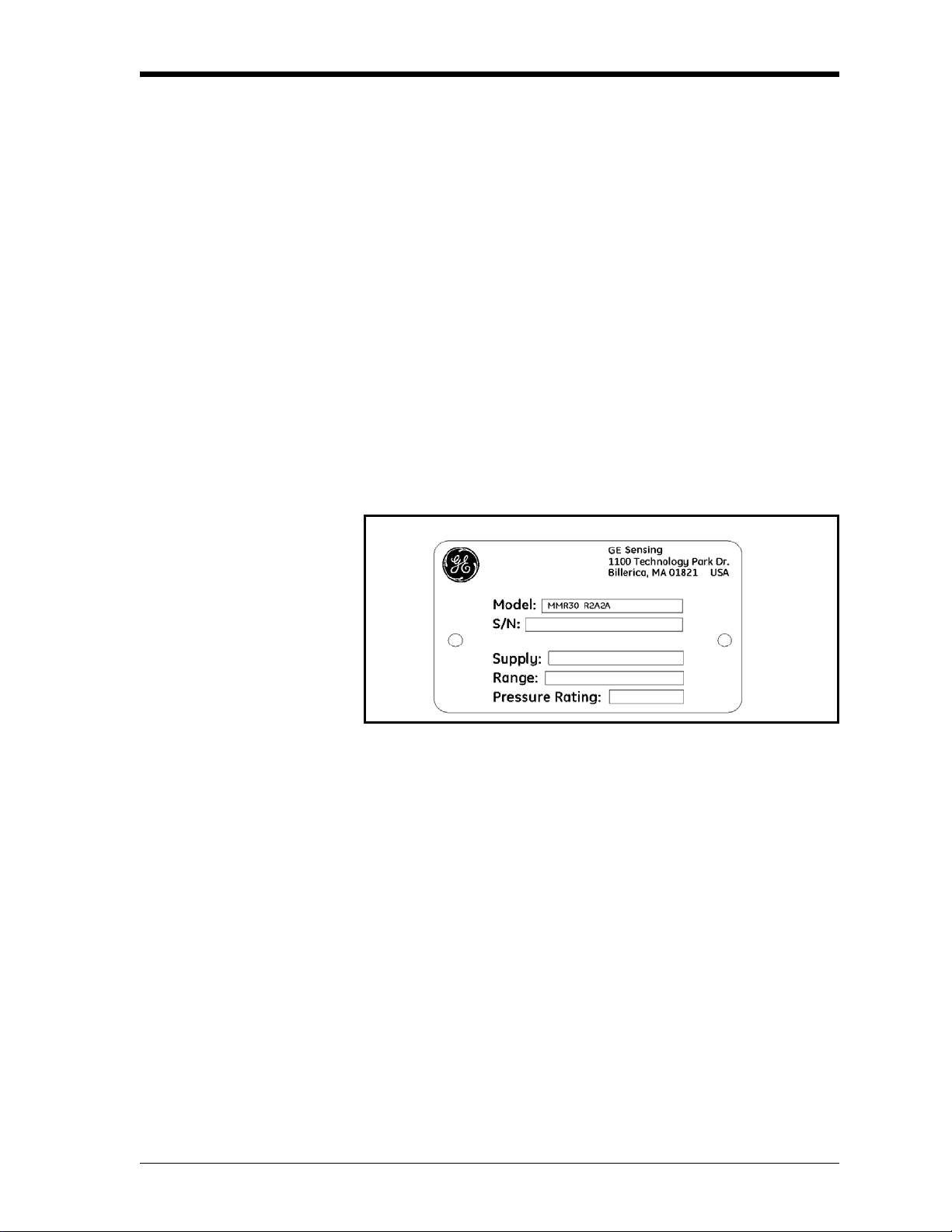
Checking the Model Number
Compare the model number (on the product label) with the product
structure (see Figure 1-1 below) to ensure you have received
everything you ordered.
Figure 1-1: Sample MMR30 Product Label with Model Number
Product S tructure MMR30
Certification/Approvals:
R Standard (not certified)
S Other
Process Connection:
1 ½” MNPT (1/4” tube fitting if B, C or D is selected below)
2 G ½ (6 mm tube fitting if B, C or D is selected below)
S Other
Orifice Configuration:
A Inlet: None; Outlet: Orifice, with ¼” FNPT connection
B Inlet: None; Outlet: Orifice, with (6 mm) ¼” tube fitting installed
C Inlet: None; Outlet: None, with (6 mm) ¼” tube fitting installed
D Inlet: Orifice; Outlet: None, with (6 mm) ¼” tube fitting installed
S Other
General System Information 1-1
Page 12
November 2005
Checking the Model
Number (cont.)
Introduction
Unit Description
Enclosure Conduit:
1 Enclosure conduit M20X 1.5-F with cable gland and plug
2 Enclosure conduit M20X 1.5-F with 1/2” NPT-F adapter and plug
S Other
Output Configuration/Dewpoint Range:
A Td -15°C to +10°C (+5°F to +185°F), no display, error 22 mA
C As A, fault status: hold
D As A, fault status: 3.6 mA
G As A, with integral display, user interface
S Other
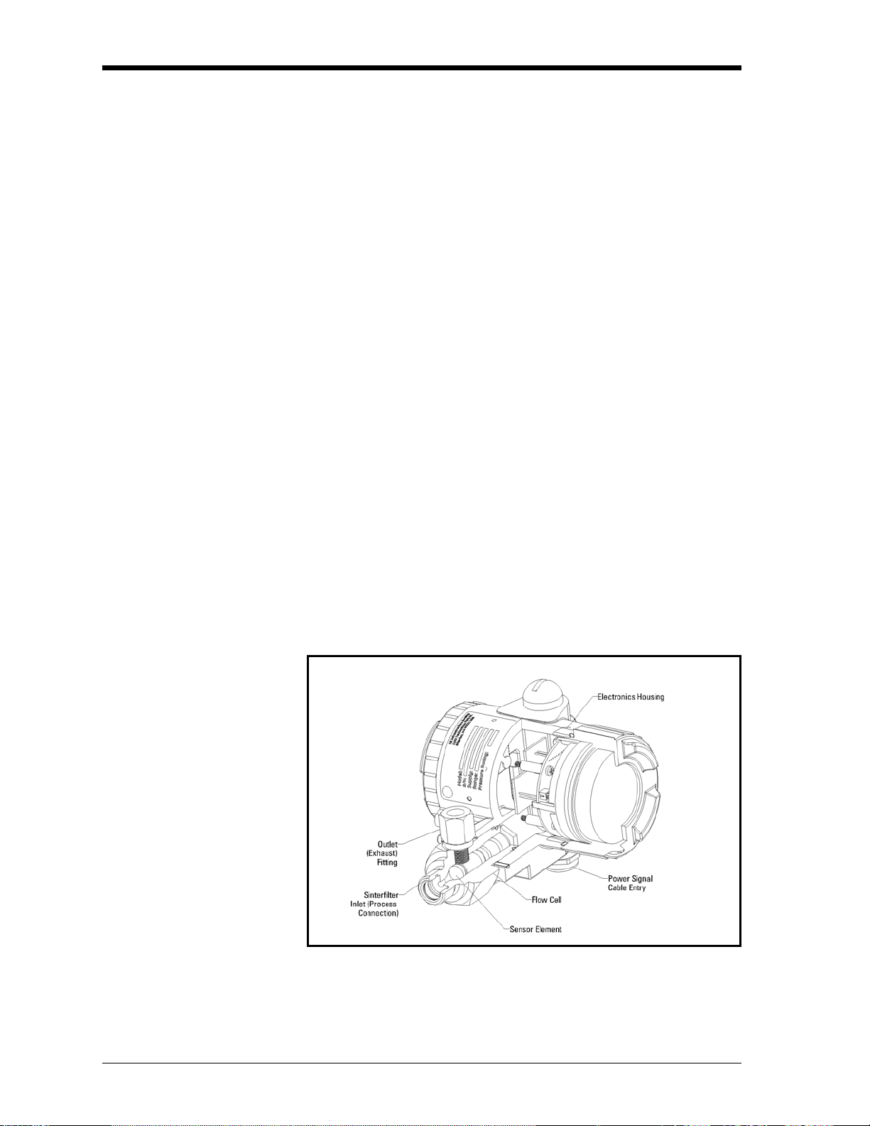
The DewPro MMR30 (shown in Figure 1-2 below) is a loop powered
mid-range moisture transmitter. The transmitter includes a sensor
element, a flow chamber, a weatherproof enclosure, microprocessor
electronics, and assorted fittings, all in a compact assembly. In most
cases, either the inlet or outlet port includes an orifice to regulate the
flow . The placement of this ori fice determines whether the dew point
measurement is done at process (line) pressure (outlet orifice), or at
atmospheric pressure (inlet orifice).
Optional Display/User Interface
The optional display/user interface feature allows the DewPro to be
configured to the user's specifications. See Chapter 4 for more
information.
Figure 1-2: The DewPro MMR30
1-2 General System Information
Page 13

November 2005
Theory of Operation
4 to 20 mA Loop The DewPro MMR30 microprocessor controlled electronics operate
with a DC voltage supply from 12 to 28 VDC. At the nominal 24
VDC supply , the maximum loop resistance is 600 Ohm. The signal is
represented by the 4 to 20 mA loop current and is directly
proportional to the dewpoint range in °C or °F. In the standard range,
4 mA corresponds to -15°C (+ 5°F) and 20 mA to +85°C (+185°F)
dew point temperature.
Bypass In dryer applications, the moisture sensor performs best when
mounted in a bypass. The built-in bypass of the DewPro eliminates
costly hardware associated with traditional sampling methods. The
DewPro installs easily into the process with its G ½ or ½” NPT-M
threaded connection.
Polymer Sensor The sensing element in the MMR30 is a silicon-based polymer that
uses the capacitance principle for the moisture measurement. The IC
chip includes the moisture sensor and appropriate integrated circuitry.
A platinum RTD temperature sensor is built in to provide temperature
compensation for maximum accuracy. The sensor element is
protected from condensation using a hydrophobic sintered filter.
Calibration Each DewPro is factory calibrated against precise NIST certified
moisture references and has an accuracy of ±1°C dew point for dew
points above 0°C. Field calibration is possible with the use of a
moisture generator. Consult the factory for details.
General System Information 1-3
Page 14
November 2005
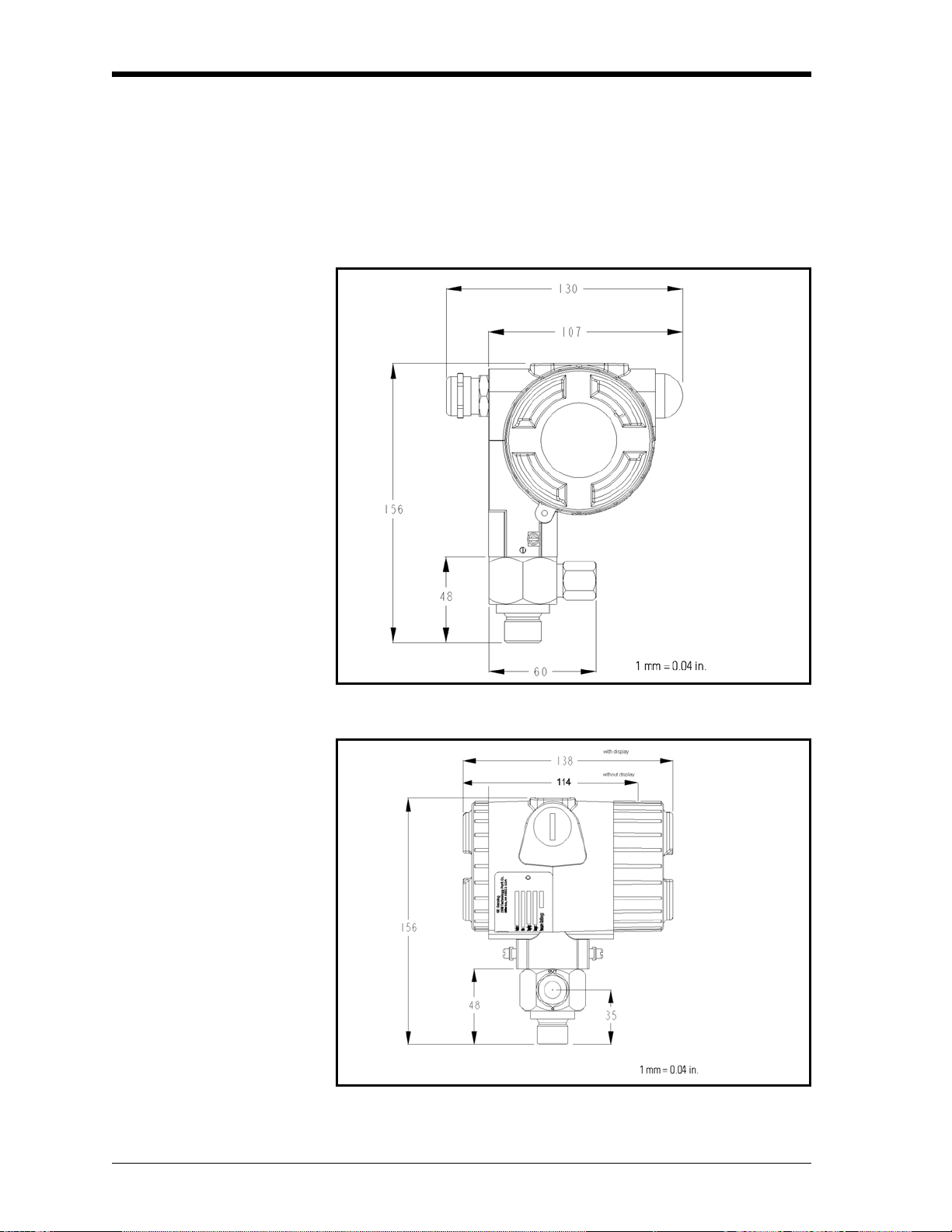
Dimensions Choose a mounting location which allows enough clearance for the
use of tools.
Fig 1-3 below shows installation dimensions for a standard DewPro,
while Figure 1-4 below shows the dimensions for a DewPro with the
optional display/user interface.
Figure 1-3: Standard DewPro Dimensions
Figure 1-4: DewPro with Optional Display/User Interface
1-4 General System Information
Page 15

Chapter 2
Page 16

Installation Guidelines
General Hints. . . . . . . . . . . . . . . . . . . . . . . . . . . . . . . . . . . . . . . . . . . . . . . . . . . 2-1
Method I - Orifice at Outlet . . . . . . . . . . . . . . . . . . . . . . . . . . . . . . . . . . . . . . 2-1
Method II - Orifice at Inlet . . . . . . . . . . . . . . . . . . . . . . . . . . . . . . . . . . . . . . . 2-3
Method III - No Flow Restriction . . . . . . . . . . . . . . . . . . . . . . . . . . . . . . . . . . 2-4
Method IV - Remote Installation . . . . . . . . . . . . . . . . . . . . . . . . . . . . . . . . . . 2-5
Page 17
General Hints Caution!
B e f o r e i n s t a l l a t i o n , p l e a s e r e a d a l l i n s t r u c t i o n s .
The DewPro is designed to be mounted to pressurized
systems. Take necessary precautions when mounting or
removing the DewPro.
November 2005
• Mount the DewPro
particles or condensation from entering the bypass.
• Mount the DewPro
DewPro when removing it from the process pipe in case of
maintenance.
Do not over-tighten! The outlet fitting is connected to the
bypass block with a G 1/4 straight thread (with gasket)
which will seal if the fitting is simply hand-tightened. When
connecting an external device, counter the fitting with a
second wrench when tightening. If the inlet is equipped
with a G 1/2 straight thread and gasket, the seal is
obtained by simply hand-tightening the DewPro®.
If you are installing the DewPro into a pressurized system
(up to 10 bar), depressurize the system before installing or
removing the sensor. Pressurized systems require a
stainless steel compression fitting.
®
vertically whenever possible to prevent
®
after a shutoff valve to depressurize the
Caution!
Caution!
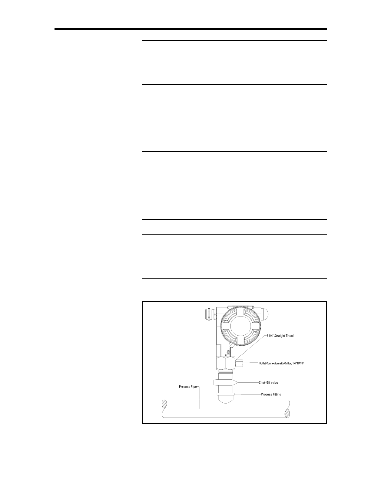
Method I - Orifice at Outlet
Figure 2-1: DewPro Installation with Orifice at the Outlet
Installation Guidelines 2-1
Page 18

November 2005
Pressure Dewpoint Refrigeration air dryers producing general instrument air are typically
specified with a pressure dewpoint rating. The majority of dryers
operate in a dewpoint range between +2°C to +10°C (+35°F to
+50°F). A pressure of 7 to 8 bar (= 100 psig) is very common.
Air Flow The DewPro is designed to measure the pressure dew point. By
restricting the flow at the outlet of the integral bypass with an orifice,
the sensor monitors the dewpoint at process pressure. The bleedoff air
to the atmosphere at 7 to 8 bar (100 psig), is approximately 70 cc/min.
(=4 l/h or =0.14 cfh). For smaller sized dryers of 3m
the air loss is only 0.002% of the air production and is negligible.
Despite the very low flow rate through the bypass as shown in Figure
2-1 on the previous page, the air sample in the DewPro bypass
chamber is refreshed every second due to the small volume design.
As a result, the sensor sees changes in moisture instantaneously.
Due to the low flow rate, the flow velocity is also very low at <0.01
m/sec. (=34m/h).The low flow velocity prevents the inlet filter from
clogging, since there is not enough kinetic energy to push dust
particles into the filter.
3
/min.(=100 cfm)
2-2 Installation Guidelines
Page 19

Method II - Orifice at Inlet
November 2005
Figure 2-2: DewPro with Orifice Restriction at Inlet
In case the application requires the dew point measurement under
atmospheric pressure, the orifice flow restriction is to be mounted at
the inlet of the DewPro
®
bypass.This may not be typical for dryer
applications. The dew point reading will be lower since the water
vapor pressure is reduced by the factor of the pressure drop across the
inlet orifice.
®
In this configuration, the outlet of the DewPro
bypass is not flow
restricted and will be equipped with a 6 mm (1/4”) tube fitting. In
order to prevent back diffusion of water vapor from the ambient air,
five feet of exhaust tubing should be mounted to the tube fitting, or,
better, a diffusion coil from GE Sensing can be used.
Installation Guidelines 2-3
Page 20

November 2005
Method III - No Flow Restriction
Low Pressure Closed Loop
Figure 2-3: DewPro with No Flow Restriction
Closed loop systems, with dew points >-15 °C, may operate at a low
pressure. The air passing through the DewPro bypass is fed back to
the main stream after a pressure drop in the main line.
In this configuration, the DewPro bypass has no flow restriction at the
inlet and outlet. The outlet is equipped with a 6 mm (1/4”) tube fitting
to allow simple connection of the loop tubing.
2-4 Installation Guidelines
Page 21

November 2005
Method IV - Remote Installation
In some cases there may not be enough room to install the DewPro
directly to the process pipe. The tube connection at the inlet allows
mounting the DewPro at a remote location, as shown in Figure 2-4
below. The functions of Methods I-III can be selected.
Figure 2-4: DewPro in Remote Installation
Mounting Brackets The DewPro can be mo unted on a wall, a plate or a pipe using a
bracket available from GE Sensing, as shown in Figure 2-5 below.
Panel Mounting
6.50 in.
(165 mm)
2.76 in.
(70 mm)
Horizontal Pipe Mounti ng
3.23 in.
(82 mm)
4.45 in.
(113 mm)
4.45 in.
(113 mm)
2.76 in.
(70 mm)
4.45 in.
(113 mm)
0.79 in.
(20 mm)
Vertical Pipe Mounting
Horizontal Pipe Mounting
Figure 2-5: DewPro with Various Mounting Brackets
Installation Guidelines 2-5
Page 22

Chapter 3
Page 23

Wiring Instructions
Wiring, General Guidelines. . . . . . . . . . . . . . . . . . . . . . . . . . . . . . . . . . . . . . . 3-1
System Configuration. . . . . . . . . . . . . . . . . . . . . . . . . . . . . . . . . . . . . . . . . . . 3-1
Mounting in Normal Environments . . . . . . . . . . . . . . . . . . . . . . . . . . . . . . . 3-2
Mounting in Environments with Severe Electrical Noise. . . . . . . . . . . . . 3-2
Electrical Connection . . . . . . . . . . . . . . . . . . . . . . . . . . . . . . . . . . . . . . . . . . . 3-3
General Instructions . . . . . . . . . . . . . . . . . . . . . . . . . . . . . . . . . . . . . . . . . . . . 3-3
Page 24

November 2005
Wiring, General Guidelines
Note: If the DewPro is equipped with an optional display/user
interface, please refer to Chapter 4.
Caution!
The DewPro system contains electronic components that
are susceptible to damage by static electricity. Proper
handling procedures must be observed during the
removal, installation, or other handling of internal boards
or devices.
System Configuration Figure 3-1 below shows various power supplies and displays for use
with the DewPro.
Figure 3-1: Power Supplies and Displays for DewPro
Designing the Loop If users provide their own power supply, the voltage at the +/-
terminal of the DewPro should not fall below 12 VDC. The maximum
loop resistance is an important measure for selection of the supply
voltage. Each device connected to the loop causes a voltage drop. For
instance, using a loop-powered display with an input impedance of 50
Ohm will cause a voltage drop of 1 VDC at 20 mA using Ohm's law.
Connecting the loop to a PLC will cause a voltage drop across the
input.
When designing your loop, add up all voltage losses across the
devices connected to the loop and add 12 V. The sum will be the
minimum supply voltage required from the power supply. Calculate
with a 20% safety factor.
Wiring Instructions 3-1
Page 25

November 2005
Mounting in Normal Environments
Mounting in Environments with Severe Electrical Noise
A standard two-wire, stranded cable (shown in Figure 3-2 below) can
be used to interconnect the DewPro with the power source.
Figure 3-2: Standard Cable for Use with DewPro
The DewPro MMR30 meets the EMC requirements of IEC 61326 for
equipment used in industrial locations. The MMR30 passed all tests
to the standards IEC 61000-4- to the performance criterion A. Test
details appear in Chapter 6, Specifications.
Figure 3-3: DewPro with Shielded Signal Cable
3-2 Wiring Instructions
Page 26

November 2005
Electrical Connection Figure 3-4 below shows the DewPro wiring connections.
Figure 3-4: DewPro Wiring Connections
General Instructions 1. Unscrew the cap on the unit.
2. Loosen the cable gland located on the side of the unit.
3. Feed the cable through the conduit opening.
Note: Use a standard signal cable size.
4. Retighten the metal cable gland to meet IP67 and to relieve any
stress on the wire.
5. Verify that a voltage between 12 and 28 V DC is across the
terminals marked + and -.
Note: This is the voltage that appears across the DewPro terminals,
not necessarily the power supply voltage due to voltage loss in
wire length, displays, and indicators.
6. In order to meet EMI/RFI immunity, a two-wire shielded cable
with a common foil shield layer is being used to power the
MMR30. Removing the insulation by 3” allows users to pull back
the foil, clamping it in between the metal cable gland. You must
connect the ground wire to the internal grounding screw.
Wiring Instructions 3-3
Page 27

Chapter 4
Page 28

Optional Display/User Interface
Installation. . . . . . . . . . . . . . . . . . . . . . . . . . . . . . . . . . . . . . . . . . . . . . . . . . . . . 4-1
Description of the DewPro MMR30 Programming Matrix . . . . . . . . . . . . 4-2
Special Functions of the Push Buttons . . . . . . . . . . . . . . . . . . . . . . . . . . . . 4-3
Functions of the Matrix. . . . . . . . . . . . . . . . . . . . . . . . . . . . . . . . . . . . . . . . . . 4-4
Page 29

November 2005
Installation If the DewPro is equipped with an optional display/user interface,
follow the procedure below to access the buttons.
Figure 4-1: DewPro with Display Assembly
DewPro with Display Assembly
1. Unscrew and remove the protective window lid from the top of the
DewPro (as shown in Figure 4-1 above), exposing the display
module below. The buttons V, H, + and - are now accessible.
Replacing the Display 2. The display unit snaps onto the printed circuit board, resting on
four posts. When removing the display, push one post to the
outside, using a small screwdriver, and pull the display out.
3. Then unplug the display cable.
Optional Display/User Interface 4-1
Page 30

November 2005
Description of the DewPro MMR30 Programming Matrix
In the DewPro MMR30 transmitter with display option, a matrixstyle input is used for programming the unit of measure, measuring
range, error status of output, and output adjustment. Each option is
assigned coordinates on the 10 by 10 matrix, specified with V
(vertical), H (horizontal) and a number for each.The following
sections describe the features and usage of the various matrix
locations as they apply to the MMR30.
Figure 4-2: The MMR30 Optional Display
The display of the DewPro MMR30 continuously shows the current
matrix location using the vertical (V) and horizontal (H) coordinates
to designate the row and column, respectively.The bar graph
represents the output current in an analog fashion (refer to Figure 4-2
above). See Appendix A for an enlarged overview of the matrix.
Table 4-1: Matrix Input for Programming
MMR30 H0 H1 H2 H3 H4 H5 H6 H7 H8 H9
Moisture Unit
Loop Range
V0
V1
Display
Moisture
Value
Select
Moisture
Unit
1 = °C
2 = °F
Dewpoint
°C 4 mA
Dewpoint
°C 20
mA
Dewpoint
°F 4 mA
Dewpoint
°F 20 mA
Loop
at Fault
1=110%
2=Hold
0=-10%
Loop Raw
Reading
V2
Constant:
Loop
Hardware
Calibration
Temperature
Unit: Loop 1
Hardware
Calibration
V3
V4
Pressure Constant in
mmHg
Display
Temperature
Value
Select Unit
of Temperature:
0 =°C
1 =°F
Loop D/A
Calibration Low
Loop D/A
Calibration
High
V5
V6
Loop 2
Hardware
Calibration
Access Key
Misc. Setup
V7
V8
V9
Display
Present Error
Previous
Error
Unit ID Software
Versi o n
Reset to
Defaults
50=Reset
Input Locking
50 =
Unlock
System
Reset
50 = Reset
4-2 Optional Display/User Interface
Page 31

November 2005
Description of the
DewPro MMR30
Programming Matrix
(cont.)
You select the desired option by entering the matrix position.
Movement through the matrix is accomplished by using the “V” and
“H” buttons to move to another row or column, as shown in the
example below . At any location where a value may be changed by the
user, the desired value is programmed using the “+” and “-” buttons.
Table 4-2: Matrix Number and Moisture Units
Matrix Moisture Unit
1Td °C
2Td °F
Example To set the dew point value to -10°C for 4 mA (V1 H2 on matrix):
1. Press the V key until the display shows V1.
2. Press the H key until the display shows H2.
3. Use the + o r - ke y to ch ange the num eric value to -10. The digit to
be changed is flashing.
4. Proceed to any part of the matrix.
Special Functions of the Push Buttons
1. Reset to “Normal” Display: Pressing the “V” and “H” buttons
simultaneously returns the user to VH 00 (normal display).
2. Display Only: Note that seven (7) matrix locations are for display
only and may not be changed by the user (refer to Table 4-1 or
Appendix). The “display only” fields are as follows:
• VH 00 = normal display (in dewpoint)
• VH 08 = indicates digitized moisture signal
• VH 40 = temperature display
• VH 90 = during a system alarm, displays the error code for the
fault encountered
• VH 91 = during normal operation, the previous error code is
displayed for reference
• VH 92 = displays the factory issued identification number
• VH 93 = displays the factory issued reference number
designating the device type and software version
3. Default Values
A default value is assigned to each programmable matrix field.
The values are present after a reset to factory programmed data
has been executed (see VH 95).
Optional Display/User Interface 4-3
Page 32

November 2005
Functions of the Matrix This section describes the functions available to the user through the
matrix grouped by common function areas. The function is accessed
by positioning to the specified location within the matrix.
System Administration Functions
1. Unlocking/Locking the Matrix
Location in
Matrix Description of Function
VH
89
This location allows the user to lock and unlock the
matrix input functions. When the matrix is locked,
“V” and “H” keys are still functional but the “+” and
“-” keys are disabled. This prevents unauthorized
modification of any of the user input functions, such
as output ranging or unit selection. Entering the
value “50” in this location unlocks the matrix. Any
other value locks the matrix.
Default: 0
2. System Reset
Location in
Matrix Description of Function
VH
99
This location allows the user to a reset of the system
electronics, similar to removing and re-applying
power to the instrument. No system parameter settings are modified. Entering the value “50” in this
location initiates the reset, and after approximately
five (5) seconds the reset is executed. After the reset,
normal operation is resumed at location VH 00.
3. Transmitter Identification
l
Location in
Matrix Description of Function
VH
92
This location displays the identification number of
the transmitter. The display should read “200.”
4. Software Version
Location in
Matrix Description of Function
VH
93
4-4 Optional Display/User Interface
This location displays the version number (3.00) of
the instrument software.
Page 33

November 2005
Moisture Measurement Functions
5. Display Present Process Value
Location in
Matrix Description of Function
VH
00
6. Select Unit of Measure for Display
Location in
Matrix Description of Function
VH
01
This location displays the present process humidity
value measured by the instrument. The unit of measure for the displayed value (i.e., dewpoint or unit
selected under VH 01) is selected in position VH 01.
The bar graph beneath the numeric display represents the position of the present value within the
range programmed for the selected unit of measure.
This location selects the unit of measure to be used
for the humidity value display. The possible selections are as follows:
1 =°C dewpoint
2 = °F dewpoint
Default: 1
7. Loop #1 at Fault
Location in
Matrix Description of Function
VH
07
This location specifies the state of current output
corresponding to the detection of a fault with either
the humidity sensor or the measurement circuitry.
The possible selections are:
0 = -10% (3.6 mA)
1 = 110% (22 mA)
2 = Hold at previous level
Default: 1
Optional Display/User Interface 4-5
Page 34

November 2005
Moisture Measurement
Functions (cont.)
Setting the Output Range for the Humidity 4-20 mA Output
8. Displaying the Moisture Frequency
Location in
Matrix Description of Function
VH
08
9. Range of Humidity Values
Assign any value to 4 and 20 mA to establish desired output range.
Location in
Matrix Description of Function Default Values
VH
12
VH
13
VH
14
When this location is selected, the A/D counts from
the moisture measurement circuit are displayed.
°C dewpoint 4 mA -15
°C dewpoint 20 mA +85
°F dewpoint 4 mA 5
VH
15
10. Pressure Constant Adjustment
Location in
Matrix Description of Function
VH
30
°F dewpoint 20 mA 185
This location allows the user to enter a value for the
process pressure. The value is entered in mmHg.
This value is only used for the calculation of the unit
grams/kg dry air.
Default: 760
4-6 Optional Display/User Interface
Page 35

November 2005
Setting the Output Range
for the Humidity 4-20 mA
Output (cont.)
11. Calibrating the Current Output
Location in
Matrix Description of Function
VH
38
VH
39
These locations are used to calibrate the 4 mA and
20 mA settings of the humidity output current loop.
This output comes calibrated from the factory and
should not normally need adjustment. To check the
setting, connect a current meter in series with the
power terminals for loop (see Chapter 3). Move to
matrix location VH 38. The output will automatically change to the 4 mA setting. Adjust as necessary using the “+” and “-” keys. Move to location
VH 39. The output will automatically change to the
20 mA setting. Again, adjust as necessary. Move to
any other matrix location to return the output to normal operation.
Note: If the matrix input is locked (VH 89), the calibration values are displayed but the current output
is unaffected.
Temperature Measurement Functions
Attention!
The standard MMR30 does not offer a temperature
measurement output. The second analog output is only
available at special request. These functions only apply to
this special version.
12. Displaying the Measured Temperature
Location in
Matrix Description of Function
VH
40
13. Selecting the Temperature Unit
Location in
Matrix Description of Function
VH
41
Selecting this location displays the present process
temperature. The unit of measure (°C/°F) is the unit
selected in location VH 41 (see Table 4-1 on page 4-
2). The bar graph displays the percentage of output
for the programmed output range.
This location allows the user to select either °C or °F
as the temperature measurement unit to be displayed
in location VH 40. Setting this location to “0”
selects °C, and setting to “1” selects °F.
Default: 0
Optional Display/User Interface 4-7
Page 36

November 2005
Error Codes 14. Display the Present Error Code
Location in
Matrix Description of Function
VH
90
This field displays a number associated with an error
code. If no error condition exists, the location displays “0.” During normal operation, it is possible for
the humidity channel to be in error, yet have a temperature channel read correctly . It is also possible for
the temperature to be in error, but have the humidity
read correctly. If a moisture unit is selected that
needs both humidity and temperature (such as dewpoint) in order to be properly calculated, the error
conditions for Td<-15°C and Td >+85°C will be set.
Follow the instructions on the next page to properly
detect the correct error code.
4-8 Optional Display/User Interface
Page 37

November 2005
Directions for Detecting the Correct Error Code
1. Take the error code display ed at the matrix location VH 90 and
divide it by 16. The digit(s) before the decimal point represent the
error code associated with the temperature channel.
Temperature Error
Bit: 0010
xxxx
Temperature <-15°C
Temperature >+40°C
Output on CH.2 less than 4 mA.
Output on CH.2 greater than 20 mA.
2. To calculate the moisture error code, take the remainder of the
previous division (the digit(s) after the decimal point) and
multiply it by 16.
Moisture Error
Bit: 0111
xxxx
RH <0%
RH >100%
Output on CH.1 less than 4 mA.
Output on CH.1 greater than 20 mA.
3. Use Table 4-3 on the next page to convert both numbers into their
respective bit codes.
Note: Every “1” corresponds to an error. See the example below
T able 4-3 for help when calculating. Please r efer to Chapter 5,
Troubleshooting, for further information.
Optional Display/User Interface 4-9
Page 38

November 2005
Directions for Detecting
the Correct Error Code
(cont.)
Table 4-3: Error Code Conversion Chart
0 0000
1 0001
2 0010
3 0011
4 0100
5 0101
6 0110
7 0111
8 1000
9 1001
10 1010
11 1011
12 1100
13 1101
14 1110
15 1111
Example 1:
Error Code: 1
1. 1/16 = 0.0625 No temperature error
2. 0.0625 x 16 = 1 Moisture error code = 1
3. Error Code Bit Map (0) (1)
0000 0001
+ >> RH < 0% (gas too dry)
Example 2:
Error Code: 39
1. 39/16 = 2.4375 Temperature error code = 2
2. 0.4375 x 16 = 7 Moisture error code = 7
3. Error Code Bit Map (2) (7)
0010 0111
++ >> Moisture Unit Selected
Depends on Temperature
+ >> Output 1 < 4mA
+ >>Temperature > + 85°C
4-10 Optional Display/User Interface
Page 39

Chapter 5
Page 40

Troubleshooting
Problems and Recommended Solutions . . . . . . . . . . . . . . . . . . . . . . . . . . . 5-1
Removing the Filter . . . . . . . . . . . . . . . . . . . . . . . . . . . . . . . . . . . . . . . . . . . . . 5-1
Page 41

November 2005
Problems and Recommended Solutions
Problem: The loop current is outside the range of 4-20 mA, as
shown on display or current meter. (In some cases, 22
mA can be ordered as the fault current.)
Solution: The process dewpoint is out of range. If the dewpoint is
above +85°C (+185°F), the current will go to 22 mA.
Apply dry air for 20 minutes. If the dewpoint doesn't
decrease, consult the factory.
If the dewpoint is below -15°C (+5°F), the current will go
below 4 mA and then to 22 mA as the fault current.
Expose the DewPro to wetter for several minutes. If the
error remains, the cause may be a defective sensor
assembly or an electronics malfunction. Consult the
factory.
Problem: There is no current.
Solution: Check the voltage and polarity across +/- terminals with a
DC voltmeter. If the voltage is within 12-28 V DC,
consult the factory.
Problem: The response time is very slow.
Solution: Verify the flow with an air flowmeter. If the orifice is at
the outlet of a 7 to 8 bar (=100 psig) process pressure, the
air flow should indicate 20 to 30 1/h (500 cc/min., 1 cfh).
If the flow is dramatically lower, the inlet filter may be
clogged. Remove the 2 micron filter and clean it with a
solvent or replace it.
Removing the Filter Figure 5-1 below illustrates filter parts for removal.
Figure 5-1: Filter Parts
Troubleshooting 5-1
Page 42

Chapter 6
Page 43

Technical Specifications
MMR30 Specifications . . . . . . . . . . . . . . . . . . . . . . . . . . . . . . . . . . . . . . . . . . . 6-1
Optional Onboard Display with User Interface. . . . . . . . . . . . . . . . . . . . . 6-2
Page 44

November 2005
MMR30 Specifications
Sensing Element Silicon-based polymer, capacitance principle, IC electronics
Measurement Range -15°C to +85°C (+5°F to +185°F)
Dew Point Accuracy ±1°C (±1.8°F) for dew points above 0°C (+32°F)
Repeatability ±1°C (±1.8°F)
Standard Operating and
-15°C to +85°C (+5°F to + 185°F)
Storage Temperature
Air Bleedoff at 7 to 8 bar (100 psig)
Maximum Operating
Approximately 28 l/h (1 cfh) (volume related to atmospheric
pressure)
17 bar, 1.7 MPa (250 psia)
Pressure
Output Loop current 4 to 20 mA; 16 µA resolution
Flow Block 316 stainless steel (1.440/1.4436) with ½” (12.7 mm) MNPT or G ½
thread (DIN ISO 228) and gasket seal
Wrench Width for Flow
42 mm (1 5/8”)
Block
Electronics Microcontroller operated
Moisture Unit Dew point temperature in °C or °F (hardware selectable)
Supply Power 24 VDC nominal, tolerance 12 to 28 VDC
Protection Type 4X (IP67)
Weight 2 kg (4.4 lbs)
European Compliance Complies with EMC Directive 89/336/EEC and PED 97/23/EC for
DN <25
Technical Specifications 6-1
Page 45

November 2005
Optional Onboard
Display with User
The optional onboard display with user interface uses a matrix
configurator for:
Interface
• range changes
• unit of measure selection
• current loop adjustment
• error diagnostics
• current value selection for fault conditions
• and entering a pressure constant for ppm
EMI/RFI Performance Criterion A:
1. Conducted Emission Test as per CISPR 11 Class A, 2004
2. Radiated Emission Test as per CISPR 11 Class A, 2004
3. Radiated Susceptibility Test as per IEC 61000-4-3, 2002
4. Electrostatic Discharge Test as per IEC 61000-4-2, 2001
.
v
5. Electrical Fast Transient Test as per IEC 61000-4-4, 2004
6. High Energy Surge Immunity Test as per IEC 61000-4-5, 2001
7. Power Frequency Magnetic Field Test as per IEC 61000-4-8, 2001
EMC IEC 61326, Industrial Locations
6-2 Technical Specifications
Page 46

Chapter 7
Page 47

Accessories
Accessories . . . . . . . . . . . . . . . . . . . . . . . . . . . . . . . . . . . . . . . . . . . . . . . . . . . . 7-1
Page 48

Accessories Single power supply
Panel mount display, power supply, no relays
Panel mount display , power supply, two alarms
Panel mount display , power supply, two alarms.
4 to 20 repeating output
Consult GE Sensing for further information.
November 2005
Accessories 7-1
Page 49

Appendix A
Page 50

Matrix Table for Programming
Page 51

November 2005
Table A-1: Matrix Input for Programming
MMR30 H0 H1 H2 H3 H4 H5 H6 H7 H8 H9
Moisture
Unit
Loop Range V1 Dewpoint
V0 Display
Moisture
Value
V2
Select Moisture Unit
1 = °C
2 = °F
°C 4 mA
Dewpoint
°C 20 mA
Dewpoint
°F 4 mA
Dewpoint
°F 20 mA
Loop
at Fault
1=110%
2=Hold
0=-10%
Loop Raw
Reading
Constant:
Loop
Hardware
Calibration
Temperature
Unit: Loop 1
Hardware
Calibration
Loop 2
Hardware
Calibration
Access Key V8 Input
V3 Pressure
Constant in
mmHg
V4 Display
Temperature
Value
V5
V6
V7
Select Unit of
Temperature:
0=°C
1=°F
Loop
D/A
Calibration
Low
Loop
D/A
Calibration
High
Locking
50 = Unlock
Misc. Setup V9 Display
Present Error
Matrix Table for Programming A-1
Previous
Error
Unit ID Software
Version
Reset to
Defaults
50=Reset
System Reset
50 = Reset
Page 52

GE Industrial
Sensing
We, GE Industrial, Sensing
1100 Technology Park Drive
Billerica, MA 01821
USA
declare under our sole responsibility that the
DewPro® MMR30 Moisture Transmitter Probe
®
DewPro
DewPro
DewPro
to which this declaration relates, are in conformity with the following standards:
• EN 61326:1997+A1+A2
®
MMY30 and MMY31 Dew Point Transmitters
®
MMR101 High-Temperature Moisture Transmitter
MMR31 Moisture Analyzer
DECLARATION
OF
CONFORMITY
following the provisions of the 89/336/EEC EMC Directive.
The units listed above and any sensors and ancillary sample handling systems supplied with them do not bear CE
marking for the Pressure Equipment Directive, as they are supplied in accordance with Article 3, Section 3 (sound
engineering practices and codes of good workmanship) of the Pressure Equipment Directive 97/23/EC for DN<25.
September 16, 2005
Date of Issue Mr. Gary Kozinski
Certification & Standards, Lead Engineer
CERT-DOC-H3 (August 2004)
Page 53

GE Industrial
Sensing
Nous, GE Industrial, Sensing
1100 Technology Park Drive
Billerica, MA 01821
USA
déclarons sous notre propre responsabilité que les
DECLARATION
DE
CONFORMITE
DewPro
DewPro
DewPro
rélatif á cette déclaration, sont en conformité avec les documents suivants:
• EN 61326:1997+A1+A2
suivant les régles de la Directive de Compatibilité Electromagnétique 89/336/EEC.
Les matériels listés ci-dessus, ainsi que les capteurs et les systèmes d'échantillonnages pouvant être livrés avec ne
portent pas le marquage CE de la directive des équipements sous pression, car ils sont fournis en accord avec la
directive 97/23/EC des équipements sous pression pour les DN<25, Article 3, section 3 qui concerne les pratiques et
les codes de bonne fabrication pour l'ingénierie du son.
16 septembre 2005
Date d’émission Mr. Gary Kozinski
®
®
MMR30 Moisture Transmitter Probe
®
DewPro
®
MMY30 and MMY31 Dew Point Transmitters
MMR101 High-Temperature Moisture Transmitter
MMR31 Moisture Analyzer
Certification et normes, ingénieur de fil
CERT-DOC-H3 (August 2004)
Page 54

GE Industrial
Sensing
Wir, GE Industrial, Sensing
1100 Technology Park Drive
Billerica, MA 01821
USA
erklären, in alleiniger Verantwortung, daß die Produkte
KONFORMITÄTS-
ERKLÄRUNG
DewPro
DewPro
DewPro
folgende Normen erfüllen:
• EN 61326:1997+A1+A2
gemäß den Europäischen Richtlinien, EMV-Richtlinie Nr.: 89/336/EG.
Die oben aufgeführten Geräte und zugehörige, mitgelieferte Sensoren und Handhabungssysteme tragen keine
CE-Kennzeichnung gemäß der Druckgeräte-Richtlinie, da sie in Übereinstimmung mit Artikel 3, Absatz 3 (gute
Ingenieurpraxis) der Druckgeräte-Richtlinie 97/23/EG für DN<25 geliefert werden.
16. September 2005
Außtellungsdatum Hr. Gary Kozinski
®
®
MMR30 Moisture Transmitter Probe
®
DewPro
®
MMY30 and MMY31 Dew Point Transmitters
MMR101 High-Temperature Moisture Transmitter
MMR31 Moisture Analyzer
Bescheinigung und Normen, Leitungsingenieur
CERT-DOC-H3 (August 2004)
Page 55

USA
1100 Technology Park Drive
Billerica, MA 01821-4111
Web: www.gesensing.com
Ireland
Shannon Industrial Estate
Shannon, County Clare
Ireland
 Loading...