

Page 1

GE
Sensing
DewPro
®
MMR101
High-Temperature Moisture Transmitter
with Two Current Loops
User’s Manual
Page 2
GE
Sensing
DewPro
®
MMR101
High-Temperature Moisture Transmitter
User’s Manual
A40251516B
November 2005
The DewPro® MMR101 Transmitter is a GE General Eastern product. GE General Eastern has joined other GE
high-technology sensing businesses under a new name—GE Sensing.
Page 3

November 2005
Warranty Each instrument manufactured by GE Sensing, Inc. is warranted to be
free from defects in material and workmanship. Liability under this
warranty is limited to restoring the instrument to normal operation or
replacing the instrument, at the sole discretion of GE Sensing, Inc.
Fuses and batteries are specifically excluded from any liability. This
warranty is effective from the date of delivery to the original
purchaser. If GE Sensing, Inc. determines that the equipment was
defective, the warranty period is:
• one year for general electronic failures of the instrument
• one year for mechanical failures of the sensor
If GE Sensing, Inc. determines that the equipment was damaged by
misuse, improper installation, the use of unauthorized replacement
parts, or operating conditions outside the guidelines specified by GE
Sensing, Inc., the repairs are not covered under this warranty.
The warranties set forth herein are exclusive and are in lieu of
all other warranties whether statutory, express or implied
(including warranties of merchantability and fitness for a
particular purpose, and warranties arising from course of
dealing or usage or trade).
Return Policy If a GE Sensing, Inc. instrument malfunctions within the warranty
period, the following procedure must be completed:
1. Notify GE Sensing, Inc., giving full details of the problem, and
provide the model number and serial number of the instrument. If
the nature of the problem indicates the need for factory service,
GE Sensing, Inc. will issue a RETURN AUTHORIZATION number (RA),
and shipping instructions for the return of the instrument to a
service center will be provided.
2. If GE Sensing, Inc. instructs you to send your instrument to a
service center, it must be shipped prepaid to the authorized repair
station indicated in the shipping instructions.
3. Upon receipt, GE Sensing, Inc. will evaluate the instrument to
determine the cause of the malfunction.
Then, one of the following courses of action will then be taken:
• If the damage is covered under the terms of the warranty, the
instrument will be repaired at no cost to the owner and returned.
• If GE Sensing, Inc. determines that the damage is not covered
under the terms of the warranty, or if the warranty has expired, an
estimate for the cost of the repairs at standard rates will be
provided. Upon receipt of the owner’s approval to proceed, the
instrument will be repaired and returned.
iii
Page 4

November 2005
Table of Contents
Chapter 1: General Information
Introduction . . . . . . . . . . . . . . . . . . . . . . . . . . . . . . . . . . . . . . . . . . . . . . . . . . . . . . . . . . . . . . . . . . . . . . . . . . . . . . . 1-1
Unpacking . . . . . . . . . . . . . . . . . . . . . . . . . . . . . . . . . . . . . . . . . . . . . . . . . . . . . . . . . . . . . . . . . . . . . . . . . . . . . . . . . 1-1
Safety Notes . . . . . . . . . . . . . . . . . . . . . . . . . . . . . . . . . . . . . . . . . . . . . . . . . . . . . . . . . . . . . . . . . . . . . . . . . . . . . . . 1-1
Order Code . . . . . . . . . . . . . . . . . . . . . . . . . . . . . . . . . . . . . . . . . . . . . . . . . . . . . . . . . . . . . . . . . . . . . . . . . . . . . . . . 1-2
Instrument Components. . . . . . . . . . . . . . . . . . . . . . . . . . . . . . . . . . . . . . . . . . . . . . . . . . . . . . . . . . . . . . . . . . . . 1-3
Mode of Operation . . . . . . . . . . . . . . . . . . . . . . . . . . . . . . . . . . . . . . . . . . . . . . . . . . . . . . . . . . . . . . . . . . . . . . . . . 1-4
Chapter 2: Installing the MR101
Introduction . . . . . . . . . . . . . . . . . . . . . . . . . . . . . . . . . . . . . . . . . . . . . . . . . . . . . . . . . . . . . . . . . . . . . . . . . . . . . . . 2-1
Manually Setting the Measurement Units. . . . . . . . . . . . . . . . . . . . . . . . . . . . . . . . . . . . . . . . . . . . . . . . . . . . 2-1
Choosing a Mounting Location. . . . . . . . . . . . . . . . . . . . . . . . . . . . . . . . . . . . . . . . . . . . . . . . . . . . . . . . . . . . . . 2-3
Mounting the Unit . . . . . . . . . . . . . . . . . . . . . . . . . . . . . . . . . . . . . . . . . . . . . . . . . . . . . . . . . . . . . . . . . . . . . . . . . . 2-4
Using a Compression Fitting . . . . . . . . . . . . . . . . . . . . . . . . . . . . . . . . . . . . . . . . . . . . . . . . . . . . . . . . . . . . 2-4
Using a Bracket . . . . . . . . . . . . . . . . . . . . . . . . . . . . . . . . . . . . . . . . . . . . . . . . . . . . . . . . . . . . . . . . . . . . . . . . 2-5
Making Electrical Connections . . . . . . . . . . . . . . . . . . . . . . . . . . . . . . . . . . . . . . . . . . . . . . . . . . . . . . . . . . . . . . 2-6
Preparation . . . . . . . . . . . . . . . . . . . . . . . . . . . . . . . . . . . . . . . . . . . . . . . . . . . . . . . . . . . . . . . . . . . . . . . . . . . . 2-6
System Configuration with One or Two 24 VDC Power Supplies . . . . . . . . . . . . . . . . . . . . . . . . . . . 2-8
System Configuration with One 24 VDC Power Supply and Loop Powered Display. . . . . . . . . 2-9
System Configuration with External Power Supply and Display . . . . . . . . . . . . . . . . . . . . . . . . . . 2-10
v
Page 5

November 2005
Table of Contents (cont.)
Chapter 3: Operating the MMR101
Introduction . . . . . . . . . . . . . . . . . . . . . . . . . . . . . . . . . . . . . . . . . . . . . . . . . . . . . . . . . . . . . . . . . . . . . . . . . . . . . . . 3-1
Powering Up . . . . . . . . . . . . . . . . . . . . . . . . . . . . . . . . . . . . . . . . . . . . . . . . . . . . . . . . . . . . . . . . . . . . . . . . . . . . . . . 3-1
Displaying Measurements . . . . . . . . . . . . . . . . . . . . . . . . . . . . . . . . . . . . . . . . . . . . . . . . . . . . . . . . . . . . . . . . . . 3-2
Description of Matrix Options . . . . . . . . . . . . . . . . . . . . . . . . . . . . . . . . . . . . . . . . . . . . . . . . . . . . . . . . . . . . . . . 3-5
System Administration Options . . . . . . . . . . . . . . . . . . . . . . . . . . . . . . . . . . . . . . . . . . . . . . . . . . . . . . . . . 3-5
Moisture Measurement Options. . . . . . . . . . . . . . . . . . . . . . . . . . . . . . . . . . . . . . . . . . . . . . . . . . . . . . . . . 3-6
Temperature Measurement Options . . . . . . . . . . . . . . . . . . . . . . . . . . . . . . . . . . . . . . . . . . . . . . . . . . . . 3-8
Error Codes and Messages. . . . . . . . . . . . . . . . . . . . . . . . . . . . . . . . . . . . . . . . . . . . . . . . . . . . . . . . . . . . . . . . 3-10
Measurement Accuracy . . . . . . . . . . . . . . . . . . . . . . . . . . . . . . . . . . . . . . . . . . . . . . . . . . . . . . . . . . . . . . . . . . . 3-11
Chapter 4: Troubleshooting
Troubleshooting . . . . . . . . . . . . . . . . . . . . . . . . . . . . . . . . . . . . . . . . . . . . . . . . . . . . . . . . . . . . . . . . . . . . . . . . . . . 4-1
Chapter 5: Maintenance
Cleaning. . . . . . . . . . . . . . . . . . . . . . . . . . . . . . . . . . . . . . . . . . . . . . . . . . . . . . . . . . . . . . . . . . . . . . . . . . . . . . . . . . . 5-1
Calibration. . . . . . . . . . . . . . . . . . . . . . . . . . . . . . . . . . . . . . . . . . . . . . . . . . . . . . . . . . . . . . . . . . . . . . . . . . . . . . . . . 5-1
Repairs . . . . . . . . . . . . . . . . . . . . . . . . . . . . . . . . . . . . . . . . . . . . . . . . . . . . . . . . . . . . . . . . . . . . . . . . . . . . . . . . . . . . 5-1
Chapter 6: Specifications
Specifications. . . . . . . . . . . . . . . . . . . . . . . . . . . . . . . . . . . . . . . . . . . . . . . . . . . . . . . . . . . . . . . . . . . . . . . . . . . . . . 6-1
vi
Page 6

Chapter 1
Page 7

General Information
Introduction. . . . . . . . . . . . . . . . . . . . . . . . . . . . . . . . . . . . . . . . . . . . . . . . . . . . 1-1
Unpacking . . . . . . . . . . . . . . . . . . . . . . . . . . . . . . . . . . . . . . . . . . . . . . . . . . . . . 1-1
Safety Notes . . . . . . . . . . . . . . . . . . . . . . . . . . . . . . . . . . . . . . . . . . . . . . . . . . . 1-1
Order Code. . . . . . . . . . . . . . . . . . . . . . . . . . . . . . . . . . . . . . . . . . . . . . . . . . . . . 1-2
Instrument Components . . . . . . . . . . . . . . . . . . . . . . . . . . . . . . . . . . . . . . . . 1-3
Mode of Operation . . . . . . . . . . . . . . . . . . . . . . . . . . . . . . . . . . . . . . . . . . . . . . 1-4
Page 8

November 2005
Introduction The MMR101 is a moisture and temperature transmitter featuring two
patented isolated 4 to 20-mA current loops. The measuring range lies
between 0 to 100% relative humidity at temperatures of up to 150
o
(300
F). This transmitter has been designed for use in low and hightemperature ranges, such as chemical processes, textile production
and the glass, cement and steel industries. This instrument can be
used in pressurized and not pressurized systems with pressures of up
to 10 bar.
o
C
Unpacking Inspect for any damaged packaging and contents. The post office or
freight carrier must be informed of any damage. Damaged
merchandise must be retained until the matter has been settled.
Check that the delivery is complete and agrees with the shipping
documents of your order (refer to nameplate for type and variant).
The delivery comprises:
• DewPro
®
MMR101
• User’s Manual
• Depending on your order: process connection and display
• Calibration certificate
If you have any questions, consult your supplier or the GE Sensing
sales agency in your area (see back cover of these operating
instructions for addresses).
Safety Notes • You should strictly adhere to the notes and warnings in this
manual.
• Operating this instrument in any way other than as described in
this manual may compromise the safety and function of the
measuring instrument.
• Troubleshooting should only be performed by authorized and
trained personnel.
• To prevent accidental startup, remove the unit from service if you
cannot remedy faults.
• Damaged equipment should be clearly identified as such to preven t
danger.
• Repair work must be performed by authorized GE Sensing Service
Personnel.
General Information 1-1
Page 9
November 2005
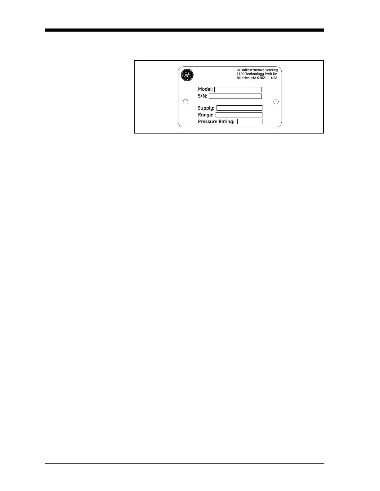
Order Code You can identify the various options for your unit by order code on
the nameplate of the instrument.
Figure 1-1:
Moisture Sensor DewPro MMR101
Certification/Approvals
R Standard (not certified)
A FM IS Class I, II, III; Division 1, Groups A-G, T4
B FM XP-IS Class I, Division 1, Groups A-D, T5
C FM NI Class, Division 2, Groups A-D, T4;
DIP Class II, III; Division 1, Groups E-G, T4
F ATEX II 3G EEx nA IIC T4
S Other
Process Connection
3 1/2” NPT-M compression fitting
8
G
½ compression fitting
6 No mounting hardware
2 ¾” NPT-M compression fitting
4 ¾” x 16 “O” ring seal compression fitting
(UNF thread)
S Other
Nameplate
Moisture output units
R % Relative Humidity
o
C
C Dew Point
o
F
F Dew Point
g/m
3
D
X g/kg
V % by volume
o
W
C Wet bulb Temperature
o
T
F Wet bulb Temperature
S Special Version
1-2 General Information
Page 10

November 2005
Display
1 With Display/User Interface
2 w/o Display, current at error: 22 mA
3 w/o Display, current at error: hold
4 w/o Display, current at error: 3,6 mA
S Special Version
Probe Length
A 16” (406 mm) long
B 9” (229 mm) long
S Special Version
MMR101R R 3 C 2 B (example of order code)
Instrument Components The DewPro MMR101 consists of the following components:
• electronics module in industrial IP 67, type 4X enclosure
• 1/2" stainless steel sensor tube
• Compression fitting, G 1/2 or 1/2" NPT thread
• Sensor:- capacitive polymer sensor for moisture measurement- Pt
1000 for temperature measurement
• Protective filter made of sintered stainless steel with a porosity of
40 pm
• Conduit adapter M20 to 1/2 NPT-M
General Information 1-3
Page 11

November 2005
Mode of Operation The MMR101 measures the relative humidity and the temperature of
the process. The sensor tube is designed for direct measurement in the
process (in-line measurement). The relative humidity is measured
using the capacitive measuring principle. The moisture sensor
consists of a capacitor with two electrodes. The dielectric constant of
an organic dielectric located between the electrodes changes with
relative humidity. The capacitance determined is converted to a
frequency by the microprocessor. This moisture signal is compared to
a calibration table permanently stored in the instrument.The relative
humidity in the process is determined based on this signal. A Pt 1000
sensor is used to measure the process temperature. The process
temperature is available to the user via a second 4 to 20 mA output. It
is also used for moisture measurement temperature compensation. All
the moisture units provided by the instrument are determined from
relative humidity and temperature.
1-4 General Information
Page 12

Chapter 2
Page 13

Installing the MR101
Introduction. . . . . . . . . . . . . . . . . . . . . . . . . . . . . . . . . . . . . . . . . . . . . . . . . . . . 2-1
Manually Setting the Measurement Units . . . . . . . . . . . . . . . . . . . . . . . . . 2-1
Choosing a Mounting Location . . . . . . . . . . . . . . . . . . . . . . . . . . . . . . . . . . . 2-3
Mounting the Unit . . . . . . . . . . . . . . . . . . . . . . . . . . . . . . . . . . . . . . . . . . . . . . 2-4
Making Electrical Connections . . . . . . . . . . . . . . . . . . . . . . . . . . . . . . . . . . . 2-6
Page 14
November 2005
Introduction Installing the MR101 consists of finding a suitable installation
location, mounting the unit and then making the necessary wiring
connections. However, if your unit does not have a display, you
should make sure the moisture units have been configured.
Use the following sections to properly install you unit:
• Selecting the Measurement Units, below
• Choosing a Mounting Location on page 2-3
• Mounting the Unit on page 2-4
• Making Electrical Connections on page 2-5
Manually Setting the
Measurement Units
If your MMR101 is not equipped with a display, your unit will
already be configured for the measurement units you specified at the
time of ordering. Use the steps below to select different units or verify
the units is setup as specified.
Note: The sensor measures r elative humidity and temperatur e. Other
moisture units are derived from these live measurements. The
o
temperature loop is 0 to 150
selectable. See Measurement Accuracy on page 3-11 for more
details on accuracy.
Use the steps below to reset the desired measurement units.
Caution!
If your instrument is connected to power, disconnect it
before performing the following procedure.
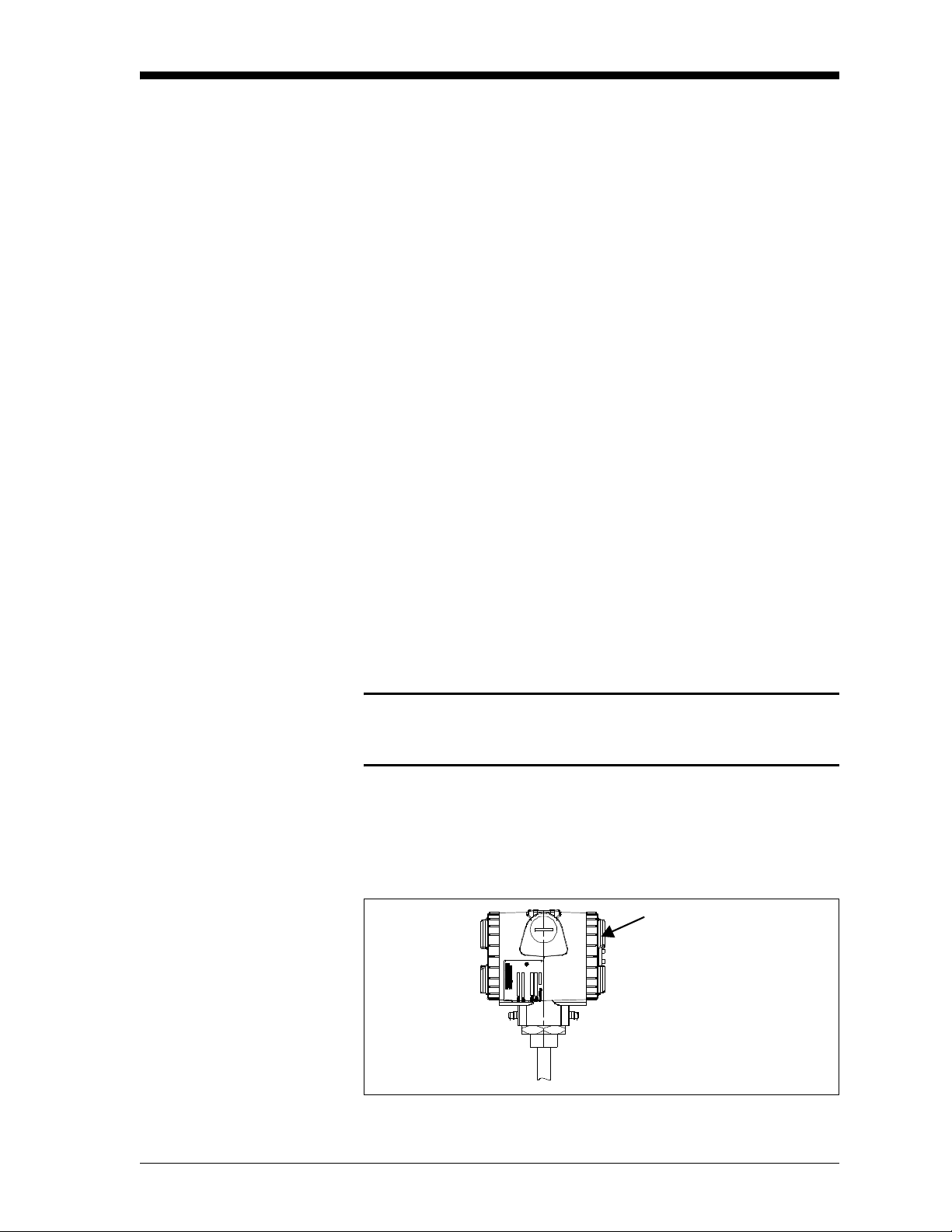
1. If your unit is already installed, disconnect it from the power
supply.
2. Remove the housing cover opposite to the terminal side.
C (32 to 300oF) and is not
Remove
This Cover
Installing the MR101 2-1
Page 15
November 2005
Manually Setting the
Measurement Units
(cont.)
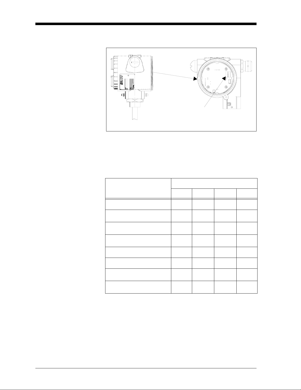
3. Locate the four DIP switches on the printed circuit board.
DIP Switches
(enlarged)
4. Use a pointed object (e.g. a screwdriver) and set switches 1-3
according to the desired output unit (see T able 2-1, below). Switch
No. 4 has no effect.
Table 2-1: DIP Switch Positions for Unit Selection
Switch No.
Unit
1234
Relative Humidity % On On On Dew Point oC
Dew Point oF
Absolute humidity g/m
Off On On -
On Off On -
3
Off Off On -
Mixing ratio g/kg On On Off Volume % Off On Off -
Wet bulb temperature oC
o
Wet bulb temperature
F
On Off Off -
Off Off Off -
2-2 Installing the MR101
Page 16

November 2005
Choosing a Mounting
Location
Choose a mounting location that allows enough clearance for
installation and convenient access during normal operation. Refer to
Figure 2-1, below.
M20 or 1/2“ NPT cable
connections for DC
power supply
5779
129
228
Microprocessor
electronics in IP67
enclosure
129
40m sintered
µ
stainless steel
fliter
Left: MMR101 Assembly 9“ Probe & integrated display/user interface
Right: MMR101 Assembly 16“ Probe, without integrated display/user interface
12.7
12.7
Figure 2-1: Dimension Drawing
412
µ
40m
sintered
stainless
steel
fliter
Installing the MR101 2-3
Page 17

November 2005
Mounting the Unit Caution!
Only trained personnel should install and operate
this unit. Be sure to follow all applicable national
electrical codes and safety codes when installing
this unit, especially for units installed
in hazardous (classified) locations (IS or XP)
You can mount the MMR101 using a:
• Compression Fitting - when installing into a pipe or container.
• Bracket - when measuring trace humidity in ambient air.
Use the appropriate section that follows to select a mounting location
and properly install and mount the MMR101.
Using a Compression
Fitting
Caution!
If you are installing the DewPro into a pressurized
system (up to 10 bar), depressurize the system before
installing or removing the sensor. Pressurized systems
require a stainless steel compression fitting.
1. If you are installing the DewPro into a pressurized system, mount
it after the shut-off valve and then depressurize the pipe/container.
2. The MMR101 is supplied with a stainless steel compression fitting
with a stainless steel ferrule. If you are supplying a fitting, it
should be a stainless steel compression fitting with the following:
• For insertion into pressurized systems, the fitting should
have a 1.471 stainless steel ferrule.
• For un-pressurized systems, the fitting only needs a nylon
ferrule; however, a stainless steel ferrule can be used.
3. Adjust the compression fitting to obtain a minimum sensor
immersion depth of 3 in. (75 mm).
4. Insert the sensor into the pipe/container into the mating connector.
Ideally, the sensor tip should be positioned in the center of the
pipe.
Caution!
When inserting the sensor into the pipe/container,
make sure it does not touch the inside wall
of the pipe/container.
5. Hand-tighten the nut.
6. Using a wrench, tighten the nut 1
properly, the fitting can withstand the specified maximum
pressure.
2-4 Installing the MR101
¼ turns. When tightened
Page 18

November 2005
Using a Bracket When measuring ambient air, the MMR101 can be mounted directly
on a wall, panel or pipe using an optional mounting kit. Mounting kits
can be ordered from the factory. Use Figure 2-2, below to properly
install your unit in the desired configuration.
6.50 in.
(165 mm)
Panel Mounting
2.76 in.
(70 mm)
4.45 in.
(113 mm)
3.23 in.
(82 mm)
4.45 in.
(113 mm)
Vertical Pipe Mounting
0.79 in.
(20 mm)
4.45 in.
(113 mm)
Horizontal Pipe Mounting
2.76 in.
(70 mm)
Horizontal Pipe Mounting
Figure 2-2: Mounting Kit Configurations
Installing the MR101 2-5
Page 19

November 2005
Making Electrical
Connections
The DewPro MMR101 is a loop-powered moisture and temperature
transmitter for two- or four-wire connection being supplied via the
signal line (moisture signal). The first circuit transmits the moisture
unit selected, the second the process temperature. The DewPro can be
optionally supplied from a common or two separate power sources
(1 2 ... 28 V DC). Additional power supply connections are not
required.
Preparation Use the steps below to make electrical connections to the instrument.
Caution!
Make sure that the voltage between the + and -
terminals lies between 12 and 28 V DC.
1. Unscrew the lateral connection cover and remove from the
housing.
2. Loosen the lateral cable gland.
Note: If you are using a cable conduit, remove the cable gland and
replace with the corresponding M20
3. Feed the cable through the cable opening. Use a shielded 4-wire
cable with an outside diameter of 5 mm or greater.
½" NPT adapter.
4. Make connection to the terminal block as shown in Figure 2-3 on
the next page. Connect the cable as follows:
Table: 2-2: Cable Connections
Position Signal
1 Temperature +
2 Temperature 3 Moisture +
4 Moisture 5 External Earth
Ground
6 Internal Earth
Ground
Note: The moisture signal output must always be connected;
connecting the temperature signal output is optional. If the
signal output for temperature is not needed, the corr esponding
terminals should not be used.
2-6 Installing the MR101
Page 20

November 2005
Preparation (cont.) 5. In order to meet EMI/RFI immunity, a 2- or 4-wire shielded cable
with a common foil shield layer is being used to power the
MMR101. Removing the insulation by 3” allows the user to pull
back the foil, clamping it in between the metal cable gland. The
ground wire must be connected to the internal grounding screw.
This way the MMR101 meets EMC requirements according to
IEC 61326, Criterion A (see details under Specifications on page
6-1).
6. Tighten the cable gland to assure protection type IP 67 and to
provide strain relief for the cable.
1 2 3 4 5 6
Figure 2-3: Terminal Block Connections
The DewPro provides various options for making electrical
connections. Use the appropriate section that follows to make
electrical connections.
Installing the MR101 2-7
Page 21

November 2005
System Configuration
with One or Tw o 24 VDC
Power Supplies
Use the figure below to make moisture and temperature connections
using one or two 24 VDC power supplies.
12-28V
12-28V
Temp.
Moisture
Figure 2-4: Connection with One or Two
24 VDC Power Supply
Connection 1 above shows a two wire line with power supply and
moisture signal output (must always be connected).
Connection 2 shows a galvanically separated signal output for
process temperature that can be connected to the same or separate
power source.
2-8 Installing the MR101
Page 22

November 2005
System Configuration
with One 24 VDC Power
Supply and Loop
Powered Display
When making electrical connection for power and the display you
should adhere to the following guidelines:
• The voltage between the + an d - terminals must not drop below
12 V DC.
• Every component connected to the loop causes a voltage drop.
To determine the supply voltage required, add up the voltage
drops of the components connected to the loop and add 12 V.
This sum is the required minimum voltage. A safety margin of
20% should added into the calculated.
• For precision measurement, make sure that both loops are
connected to the power supply at the power supply, do not use
a jumper at the transmitter terminals.
• Adapt the external display to the following measuring ranges
based on the 4 to 20 mA current range:
• 0 to 100% relative humidity
• -40 to 100
• -40 to 212
o
C dew point (up to 150
o
F dew point (up to 300
• 0 to 1000 g/m
3
absolute humidity
o
C for pressurized systems)
o
F for pressurized systems)
• 0 to 1000 g/kg mixing ratio
• 0 to 100% by volume
• -40 to 212
Use the Figure 2-5, below to make moisture and temperature
connections using one or two 24 VDC power supplies.
o
F wet bulb temperature
12...28 VDC
Figure 2-5: Connection with One 24 VDC Power Supply
Installing the MR101 2-9
Page 23

November 2005
System Configuration
with External Power
Supply and Display
Use Figure 2-6, below to make electrical connections for the external
power supply and display.
115/230 VAC
115/230 VAC
Figure 2-6: Connection with External Power Supply and Display
2-10 Installing the MR101
Page 24

Chapter 3
Page 25

Operating the MMR101
Introduction. . . . . . . . . . . . . . . . . . . . . . . . . . . . . . . . . . . . . . . . . . . . . . . . . . . . 3-1
Powering Up . . . . . . . . . . . . . . . . . . . . . . . . . . . . . . . . . . . . . . . . . . . . . . . . . . . 3-1
Displaying Measurements . . . . . . . . . . . . . . . . . . . . . . . . . . . . . . . . . . . . . . . 3-2
Description of Matrix Options . . . . . . . . . . . . . . . . . . . . . . . . . . . . . . . . . . . . 3-5
Error Codes and Messages. . . . . . . . . . . . . . . . . . . . . . . . . . . . . . . . . . . . . . 3-10
Measurement Accuracy . . . . . . . . . . . . . . . . . . . . . . . . . . . . . . . . . . . . . . . . 3-11
Page 26

November 2005
Introduction This section gives a brief description of the MMR101 operation
including powering up and displaying measurements. This section
includes the following:
• Powering Up
• Displaying Measurements
• Measurement Accuracy
Use these instructions to properly operate the MMR101.
Caution!
To ensure the safe operation of this unit, you
must install and operate the MMR101 as described
in this manual. In addition, be sure to follow
all applicable safety codes and regulations
for installing electrical equipment in your area.
Powering Up Caution!
Before powering up make sure that all equipment
in proximity to the unit (e.g. valve, pumps, etc.)
is functioning properly.
The MMR101 has a power supply that accepts 12 to 28 VDC (24
VDC nominal). After making electrical connections, including
grounding, as described in the previous section, Installing the MR101,
connect power. Use the following section to display the desired data.
IMPORTANT: The power line/connection is the main disconnect
device.
Operating the MMR101 3-1
Page 27

November 2005
Displaying
Measurements
If your MR101 is supplied with a display, you can display the desired
measurements using the key located to the left and right of the display
as shown in Figure 3-1, below. Units without the display, must be
manually setup as described in Manually Setting the Measurement
Units on page 2-1.
Figure 3-1: Display and Keys
The available measurements options are arranged in a matrix format.
Each option is assigned coordinates on the 10 by 10 matrix, specified
with V (vertical), H (horizontal) and a number for each. You select
the desired option by entering the matrix position. The matrix, on the
next page, shows all the possible options. See below for an example
of how to program the unit.
Example:
To set the dew point value to 5oC for 4 mA (V1 H3 on matrix):
1. Press the V key until the display shows V1.
2. Press the H key until the display shows H3.
3. Use the + or - key to change the numeric value to 5.
4. Proceed to any part of the matrix.
See Description of Matrix Options on page 3-5 for a description of all
the possible options.
Note: You can return to position V0 H0 from any field by pressing
the V and H keys simultaneously.
3-2 Operating the MMR101
Page 28

November 2005
MMR101 H0 H1 H2 H3 H4 H5 H6 H7 H8 H9
V0
V1
V2
V3
V4
Display
Moisture
Value
%RH
4 mA
Volume %
4 mA
Pressure
Constant in
mmHg
Display
Temp. Value
Select
Display Unit
%RH
20 mA
Volume %
20 mA
Select
Display Unit
o
0 =
C
o
F
1 =
Select
Output Unit
Dew point
o
C 4 mA
o
C Wet bulb
4 mA
Dew point
o
C 4 mA
o
C Wet bulb
20 mA
Dew point
o
F 4 mA
o
F Wet bulb
4 mA
Dew point
o
F 4 mA
o
F Wet bulb
g/m
4 mA
3
20 mA
Temp. 4 mA Temp. 20
mA
Loop # 1 at
Fault
0 = 110%
1 = −10%
2 = Hold
3
g/m
20 mA
Loop # 1 at
Fault
0 = 110%
1 = −10%
2 = Hold
Display
Moisture
Freq.
g/kg
4 mA
Output #1
D/A Cal
4 mA
g/kg
4 mA
Output #1
D/A Cal
20 mA
V5
V6
V7
V8
Display
V9
Matrix Moisture Units: 0=% Relative Humidity 3=g/m
present
Error Code
1=Dew Point
2=Dew Point
o
C4=g/kg7=
o
F5=% by vol.
Software
Version
3
6=oC wet bulb temp.
o
F wet bulb temp.
Output #2
D/A Cal
4 mA
Output #2
D/A Cal
20 mA
Input
Locking
50 = unlock
System
Reset
50 = Reset
Operating the MMR101 3-3
Page 29

November 2005
Description of Matrix
Options
System Administration
Options
The options available can be divided up into the following groups:
• system administration
• moisture measurement
• temperature measurement
• error codes/messages
Use the tables below for a description of each option and the
corresponding matrix coordinates.
Table 3-1: System Administration Options
Location of Matrix Description of Function
Unlock/Lock the Matrix
V8 H9
Unlocks and locks the matrix functions.
When the matrix is locked, the V and H
keys continue to be functional, but the +
and - keys are disabled. This prevents
unauthorized changes to the user
functions. Entering the value, 50 unlocks
the matrix. Entering any other value
locks the matrix.
Default: 0
V9 H9
V9 H3
System Reset
Resets the instrument settings, similar to
switching the instrument off and back on
again. No instrument settings are
changed. Entering a value of 50 in this
position initiates the reset, which is
performed after approx. 5
seconds.Normal operation in matrix
position VH 00 is resumed after the
reset.
Default: 0
Software Version
Displays the software version installed in
the instrument.
Operating the MMR101 3-5
Page 30

November 2005
Moisture Measurement
Options
Table 3-2: Moisture Measurement Options
Location of Matrix Description of Function
Measured Values Display
V0 H0
V0 H1
V0 H2
Displays the measured process humidity
value. The bar graph shows the output
value for the programmed output range
as a percentage.
Selection of the Unit
Unit to be used to display the moisture
value in matrix field V0 H0.
Options available:
0 = % relative humidity
o
C dew point
1 =
o
F dew point
2 =
3 = g/m
3
4 = g/kg
5 = % of volume
o
C wet bulb temperature
6 =
o
F wet bulb temperature
7 =
Default = pre selected based on order
code
Sets the moisture range of the 4 to 20
mA output (circuit 1)
Unit to be used for the 4 to 20 mA
moisture output. The same selections are
available as in position V0 H1. The
display and current output units are
selected independent of each other.
Options available, see V0 H1
Default = pre-selected based on order
code
Loop 1 at fault (circuit 1)
V0 H7
Status of current output 1 according to
error detection by the moisture sensor or
measuring circuit.
Options available:
0 = 110% (22 mA)
1 = -10% (3.6 mA)
2 = hold at previous level
Default: on instruments equipped with
display: 0 on instruments not equipped
with display: selected by order code
3-6 Operating the MMR101
Page 31

November 2005
Moisture Measurement
Options (cont.)
Table 3-2: Moisture Measurement Options (cont.)
Location of Matrix Description of Function
Display of frequency measured (circuit
1)
V0 H8
Displays the current moisture frequency.
Adjustment of moisture range for 4 to
20 mA output (circuit 1)
V1 H0
V1 H1
V1 H2
V1 H3
V1 H4
V1 H5
V1 H6
V1 H7
V1 H8
V1 H9
V2 H0
V2 H1
V2 H2
V2 H3
V2 H4
V2 H5
% RH = 4 mA, default 0
% RH = 20 mA, default 100
o
C dew point = 4 mA, default -40
o
C dew point = 20 mA, default 100
o
F dew point = 4 mA, default -40
o
F dew point = 20 mA, default 212
3
= 4 mA, default 0
g/m
3
= 20 mA, default 1000
g/m
g/kg dry air = 4 mA, default 0
g/kg dry air = 20 mA, default 1000
% by volume = 4 mA, default 0
% by volume = 20 mA, default 100
o
C wet bulb temp. = 4 mA, default -40
o
C wet bulb temp.= 20 mA, default 150
o
F wet bulb temp.= 4 mA, default -40
o
F wet bulb temp.= 20 mA, default 300
V3 H0
V3 H8
V3 H9
Constant pressure adjustment
This function can be used to enter a value
for the process pressure (in mm Hg
column). This value is only needed to
compute the mixing ratio in g/kg.
Default: 760
Adjustment of current output 1
Adjustment of the 4 to 20 mA hardware
settings for the moisture output. This
output is pre adjusted by the factory and
normally does not need readjustment. To
check the setting, connect a current
measuring instrument in series with circuit
1 (see chapter 2). The output signal in
position V3 H8 is automatically switched
to the 4 mA setting, and V3 H9 is
automatically switched to the 20 mA
setting. The + and - keys can be used for
fine adjustment. Move on to any other
matrix field to return the current value
measured.
Operating the MMR101 3-7
Page 32

November 2005
Temperature
Measurement Options
Table 3-3: Temperature Measurement Options
Location of Matrix Description of Function
Current
V4 H0
V4 H1
V4 H5
V4 H6
Displays the temperature measured. The
bar graph shows the output value for the
programmed output range as a percentage.
Selection of unit
Unit of measure to be used to display the
temperature in matrix field V4 H0.
Options available for selection:
o
0 =
C
o
F
1 =
Adjustment of temperature range of 4
to 20 mA output (circuit 2)
Unit value of measure to be used for the 4
to 20 mA temperature output. The value
range for both positions lies between 0
and 150. The output range is always
o
specified in
C independent of the display
unit selected.
Default: 0 (V5 H5) …. 150 (V4 H6)
Loop 2 at fault
V4 H7
Status of current output 2 when an error
has occurred in the temperature measuring
circuit.
Options available for selection:
0 = 110% (22 mA)
1 = - 10% (3.6 mA)
2 = hold at previous level Default: on
instruments equipped with display: 0 on
instruments not equipped with display:
selected by order code.
3-8 Operating the MMR101
Page 33

Temperature
Measurement Options
(cont.)
November 2005
Table 3-3 Temperature Measurement Options (cont.)
Location of Matrix Description of Function
Adjustments of current output 2
V7 H8
V7 H9
Adjustment of 4 to 20 mA hardware
settings for the temperature output. This
output is pre adjusted by the factory and
normally does not need readjustment. To
check the setting, connect a current
measuring instrument in series with
circuit 2. The output signal in position
V7 H8 is automatically switched to the 4
mA setting, and V7 H9 is automatically
switched to the 20 mA setting. The + and
- keys can be used for fine adjustment.
Move on to any other matrix field to
return the output signal to reflect current
measured values.
Default: On instruments not equipped
with display: based on order code
Operating the MMR101 3-9
Page 34

November 2005
Error Codes and
Messages
The MMR101 has a series of error codes and messages that appear on
the display to indicate certain conditions.
Note: Fields that display data cannot be modified. Fields that can be
modified have a flashing digit.
Table 3-4: Error Codes and Messages
Location
of Matrix Description of Function
" - - - - " If this appears in the matrix field, it indicates that the
matrix position is assigned.
V9 H0
Displays the current error code. If no error code is
active, dashes ("- - - ") are displayed in this matrix
position. If several errors exist, the error codes are
displayed using the following priority:
Error Code Error Status
401 Moisture sensor error
201 Relative humidity outside upper
measuring range
202 Relative humidity outside lower
measuring range
203 Temperature outside upper
measuring range
204 Temperature outside lower
measuring range
205 RH loop span too large
206 RH loop span too small
207 Temperature loop span too large
208 Temperature loop span too small
3-10 Operating the MMR101
Page 35

November 2005
Measurement Accuracy The sensor measures relative humidity and temperature. Other
moisture units are derived from these live measurements.
The accuracy of the instrument is specified as a percentage of relative
humidity. Inaccuracy is a result of the temperature dependence of
relative humidity. This dependence is due to physical properties and
is independent of the measuring apparatus. The influence of
temperature fluctuation should be taken into account for relative
humidity, as well as the derived moisture units.
Table 3-5, below shows the influence of temperature fluctuations of
o
± 1
C on relative humidity.
Table 3-5: Change in Relative Humidity
as a Function of the Temperature
Temperature
RH
o
C20
10
o
C30
o
C40
o
C50
10% ± 0,7% ± 0,6% ± 0,5% ± 0,5% ± 0,5%
50% ± 3,5% ± 3,2% ± 3,0% ± 2,6% ± 2,3%
90% ± 6,3% ± 5,7% ± 5,4% ± 4,6% ± 4,1%
o
Note: The temperature loop is 0 to 150
C (32 to 300oF).
o
C
Operating the MMR101 3-11
Page 36

Chapter 4
Page 37

Troubleshooting
Page 38

Troubleshooting
November 2005
Failure Possible Cause Remedy
Current
signal out-
side 4 to
20 mA
range
The sensor circuit has
measured a value which
lies outside the
calibration table range.
This may be caused by
very dry process
conditions (current < 4
mA) or by
condensation effects on
the sensor (current > 20
mA).
Check the display diagram
on instruments equipped
with the optional display
module.
If the signal arrows on
either side are lit or error
code 201 or 202 is
displayed in pos. V9 H0,
this means that the
measuring range has been
exceeded. Remove the
sensor from the process
and expose it to ambient air
or another air source with a
relative humidity between
10 and 90%.
Contact GE Sensing if the
measured value does not
return to the 10 to 90%
range.
The dew point or
another operand is
outside the permissible
range.
All operands are limited by
specific output ranges. The
signal arrows on the
display module only light
up when the relative
humidity lies outside the
calibration range. The
computed quantity , e.g. for
the dew point, may be
outside the operating range
for several combinations of
temperature and relative
humidity
Operation outside these
ranges does not damage the
instrument.
Troubleshooting 4-1
Page 39

November 2005
Failure Possible Cause Remedy
No power Incorrect instrument
connection.
Check the voltage and
polarity at the + and connection terminals. The
voltage should be between
12 and 28 VDC.
Contact GE Sensing if
there is no current flow
even though the voltage
and polarity are correct.
Instru-
ment
response
too slow
The protective filter is
soiled.
Remove the instrument
from the process. Unscrew
the protective filter and
clean it with a solvent (e.g.
hexing, cleaner's naphtha).
If possible, blow clean air
(oil- and dust-free) through
the filter to loosen dirt.
Note: The instrument settings and calibration data are retained in
the event of a power failure thanks to storage in non-volatile
memory.
4-2 Troubleshooting
Page 40

Chapter 5
Page 41

Maintenance
Cleaning . . . . . . . . . . . . . . . . . . . . . . . . . . . . . . . . . . . . . . . . . . . . . . . . . . . . . . . 5-1
Calibration . . . . . . . . . . . . . . . . . . . . . . . . . . . . . . . . . . . . . . . . . . . . . . . . . . . . . 5-1
Repairs . . . . . . . . . . . . . . . . . . . . . . . . . . . . . . . . . . . . . . . . . . . . . . . . . . . . . . . . 5-1
Page 42

November 2005
Cleaning Particulate substances in the process gas may clog the protective
filter. This may impair the function of the sensor.
Remove the filter and clean with a strong (halogen-free) solvent or by
flushing with oil- and dust-free, dry air.
In the case of processes with a high concentration of finely distributed
particles, additional filtering may be required to prevent clogging of
the sintered protective filter.
Make sure that the filter does not contain any solvent residue before
screwing it back onto the sensor.
The sensor element must always be handled very carefully. If soiled,
it may be briefly swished in a solvent (pure hexing, toluene or
acetone).
After cleaning the sensor with solvent, allow sufficient time for it to
dry before reinstalling it.
Calibration Factory Calibration
Fifty-five calibration values covering the entire measuring range are
determined at the factory. NIST-certified reference instruments are
used for calibration (NIST = National Institute for Standardization
Technology). The calibration certificate supplied with the sensor
confirms that the sensor matches the reference values.
Recalibrations
Just like moisture measurement, the recalibration cycle greatly
depends on the operating conditions (contamination, aggressive
media, etc.) and sensor stress. Under normal process conditions, the
sensor check / recalibration should be performed after one to two
years.
This cycle may be longer or shorter depending on operating
conditions and accuracy requirements.
Field Validation
The user can perform a sensor check in the field. This validation takes
place at room temperature (approx. 25
solutions. It is intended as a decision aid in determining whether or
not recalibration or sensor replacement is required.
o
C) using saturated salt
This check should be performed using an GE Sensing test unit with
saturated salt solutions of 11.3 and 75.4% relative humidity that can
be ordered from the factory.
Repairs Repairs must be carried out directly by the manufacturer or by the GE
Sensing Service Engineer.
Maintenance 5-1
Page 43

Chapter 6
Page 44

Specifications
Page 45

Specifications
Parameter Specification
Sensing Element Polymer; capacitance
RH Range 0 to 100%
RH Accuracy
± 2% up 65
Temperature Sensor Platinum RTD
Temperature Accuracy
Temperature Resolution
Operating Temperature
Range
Maximum Operating
± 1.1
o
0.05
Process: 0
Electronics: -40
150 psi (10.2 bar)
Pressure
Electronics Microcontroller operated, loop-powered
Loop Power Supply 24 VDC nominal, 12 to 28 VDC range
o
C (150oF) process temperature
o
C (± 2oF)
C (0.09oF)
o
C to +150oC (+32oF to +300oF)
o
C to +85oC (-40oF to 185oF)
November 2005
Outputs Two fully isolated 4 to 20 mA current loops (moisture and tempera-
Hardware Selectable Units
Standard Temperature
Output
Display Four-digit number display with bar graph and matrix position indica-
Protection Type 4X/IP67
Probe Tube 16-in. (406 mm) Probe: 316 stainless steel, 0.5 in diameter. Adjust-
Typical Mounting Adapter
Sensor Guard 40 micron sintered filter, 316 stainless steel cap
Weight 4.4 lbs (2 kg)
ture) patented (U.S. patent #5,677,476)
0% to 100% RH, -40
o
F or 150oC under system pressure), 0 to 1000 g/m3 absolute
300
o
C to 100oC or -40oF to 212oF dew point (up to
humidity, and 0 to 1000 g/kg mixing ratio dry air, 0 to 100% by vol-
o
ume, -40
o
0
C to 150oC (32oF to 300oF) range
C to 100oC or -40oF to 212oF wet bulb temperature.
tion. Four user interface keys for unit selections, output adjustments
and ranging.
able insertion length from 3 in. (76 mm) to 14.25 in. (362 mm)
9-in. (228 mm) Probe: 3 in. (76 mm) to 7.25 in. (184 mm).
1/2 in. tube
x 1/2 in. NP T-M or G1/2 compression fitting; flanges and
other sizes available upon request.
Specifications 6-1
Page 46

November 2005
Parameter Specification
EMI/RFI Protection Meets IEC 61326
Performance Criterion A:
- Conducted Emission Test as per CISPR 11 Class A, 2004
- Radiated Emission Test as per CISPR 11 Class A, 2004
- Radiated Susceptibility Test as per IEC 61000-4-3, 2002
- Electrostatic Discharge Test as per IEC 61000-4-2, 2001
- Electrical Fast Transient Test as per IEC 61000-4-4, 2004
- High Energy Surge Immunity Test as per IEC 61000-4-5,
2001
- Power Frequency Magnetic Field Test as per IEC 61000-4-8,
2001
Optional Certifications/
Approvals
• FM IS Class I, II, III, Division 1, Groups A, B, C, D, E, F & G , T4
• FM XP-IS Class I, Division 1, Groups A, B, C & D, T5
• FM NI Class I, Division 2, Groups A, B, C & D, T4A
DIP Class II, III, Division 1, Groups E, F & G, T4
• ATEX II 3G EEx nA IIC T4
6-2 Specifications
Page 47

GE Industrial
Sensing
We, GE Industrial, Sensing
1100 Technology Park Drive
Billerica, MA 01821
USA
declare under our sole responsibility that the
DewPro® MMR30 Moisture Transmitter Probe
®
DewPro
DewPro
DewPro
to which this declaration relates, are in conformity with the following standards:
• EN 61326:1997+A1+A2
®
MMY30 and MMY31 Dew Point Transmitters
®
MMR101 High-Temperature Moisture Transmitter
MMR31 Moisture Analyzer
DECLARATION
OF
CONFORMITY
following the provisions of the 89/336/EEC EMC Directive.
The units listed above and any sensors and ancillary sample handling systems supplied with them do not bear CE
marking for the Pressure Equipment Directive, as they are supplied in accordance with Article 3, Section 3 (sound
engineering practices and codes of good workmanship) of the Pressure Equipment Directive 97/23/EC for DN<25.
September 16, 2005
Date of Issue Mr. Gary Kozinski
Certification & Standards, Lead Engineer
CERT-DOC-H3 (August 2004)
Page 48

GE Industrial
Sensing
Nous, GE Industrial, Sensing
1100 Technology Park Drive
Billerica, MA 01821
USA
déclarons sous notre propre responsabilité que les
DECLARATION
DE
CONFORMITE
DewPro
DewPro
DewPro
rélatif á cette déclaration, sont en conformité avec les documents suivants:
• EN 61326:1997+A1+A2
suivant les régles de la Directive de Compatibilité Electromagnétique 89/336/EEC.
Les matériels listés ci-dessus, ainsi que les capteurs et les systèmes d'échantillonnages pouvant être livrés avec ne
portent pas le marquage CE de la directive des équipements sous pression, car ils sont fournis en accord avec la
directive 97/23/EC des équipements sous pression pour les DN<25, Article 3, section 3 qui concerne les pratiques et
les codes de bonne fabrication pour l'ingénierie du son.
16 septembre 2005
Date d’émission Mr. Gary Kozinski
®
®
MMR30 Moisture Transmitter Probe
®
DewPro
®
MMY30 and MMY31 Dew Point Transmitters
MMR101 High-Temperature Moisture Transmitter
MMR31 Moisture Analyzer
Certification et normes, ingénieur de fil
CERT-DOC-H3 (August 2004)
Page 49

GE Industrial
Sensing
Wir, GE Industrial, Sensing
1100 Technology Park Drive
Billerica, MA 01821
USA
erklären, in alleiniger Verantwortung, daß die Produkte
KONFORMITÄTS-
ERKLÄRUNG
DewPro
DewPro
DewPro
folgende Normen erfüllen:
• EN 61326:1997+A1+A2
gemäß den Europäischen Richtlinien, EMV-Richtlinie Nr.: 89/336/EG.
Die oben aufgeführten Geräte und zugehörige, mitgelieferte Sensoren und Handhabungssysteme tragen keine
CE-Kennzeichnung gemäß der Druckgeräte-Richtlinie, da sie in Übereinstimmung mit Artikel 3, Absatz 3 (gute
Ingenieurpraxis) der Druckgeräte-Richtlinie 97/23/EG für DN<25 geliefert werden.
16. September 2005
Außtellungsdatum Hr. Gary Kozinski
®
®
MMR30 Moisture Transmitter Probe
®
DewPro
®
MMY30 and MMY31 Dew Point Transmitters
MMR101 High-Temperature Moisture Transmitter
MMR31 Moisture Analyzer
Bescheinigung und Normen, Leitungsingenieur
CERT-DOC-H3 (August 2004)
Page 50

USA
1100 Technology Park Drive
Billerica, MA 01821-4111
Web: www.gesensing.com
Ireland
Shannon Industrial Estate
Shannon, County Clare
Ireland
 Loading...