

Page 1

GE
Sensing
HygroTrace
Moisture Transmitter
User’s Guide
Page 2
GE
Sensing
HygroTrace
Moisture Transmitter
User’s Guide
916-102A3
September 2007
The HygroTrace Moisture Transmitter is a GE Panametrics product.
GE Panametrics has joined other GE high-technology sensing businesses
under a new name—GE Sensing.
Page 3

September 2007
Warranty
Each instrument manufactured by GE Infrastructure Sensing,
Inc. is warranted to be free from defects in material and
workmanship. Liability under this warranty is limited to
restoring the instrument to normal operation or replacing the
instrument, at the sole discretion of GE. Fuses and batteries
are specifically excluded from any liability. This warranty is
effective from the date of delivery to the original purchaser. If
GE determines that the equipment was defective, the warranty
period is:
• one year from delivery for electronic or mechanical failures
• one year from delivery for sensor shelf life
If GE determines that the equipment was damaged by misuse,
improper installation, the use of unauthorized replacement
parts, or operating conditions outside the guidelines specified
by GE, the repairs are not covered under this warranty.
The warranties set forth herein are exclusive and are in lieu
of all other warranties whether statutory, express or
implied (including warranties or merchantability and fitness
for a particular purpose, and warranties arising from course
of dealing or usage or trade).
iii
Page 4

September 2007
Return Policy
If a GE Infrastructure Sensing, Inc. instrument malfunctions
within the warranty period, the following procedure must be
completed:
1. Notify GE, giving full details of the problem, and provide the
model number and serial number of the instrument. If the
nature of the problem indicates the need for factory
service, GE will issue a RETURN AUTHORIZATION NUMBER
(RAN), and shipping instructions for the return of the
instrument to a service center will be provided.
2. If GE instructs you to send your instrument to a service
center, it must be shipped prepaid to the authorized repair
station indicated in the shipping instructions.
3. Upon receipt, GE will evaluate the instrument to determine
the cause of the malfunction.
Then, one of the following courses of action will then be taken:
• If the damage is covered under the terms of the warranty,
the instrument will be repaired at no cost to the owner and
returned.
• If GE determines that the damage is not covered under the
terms of the warranty, or if the warranty has expired, an
estimate for the cost of the repairs at standard rates will be
provided. Upon receipt of the owner’s approval to proceed,
the instrument will be repaired and returned.
iv
Page 5

September 2007
Table of Contents
Introduction . . . . . . . . . . . . . . . . . . . . . . . . . . . . . . . . . . . . . . . . . . . . . . . 1
Installation . . . . . . . . . . . . . . . . . . . . . . . . . . . . . . . . . . . . . . . . . . . . . . . . 1
Sample System Guidelines. . . . . . . . . . . . . . . . . . . . . . . . . . . . . . 1
Insertion into the Sample System/Process. . . . . . . . . . . . . . . 3
Standard Wiring Connections. . . . . . . . . . . . . . . . . . . . . . . . . . . 4
Digital Communications Wiring Connections . . . . . . . . . . . . 7
Powering Up. . . . . . . . . . . . . . . . . . . . . . . . . . . . . . . . . . . . . . . . . . . 8
Using the HygroTrace . . . . . . . . . . . . . . . . . . . . . . . . . . . . . . . . . . . . . . 9
Keypad Features. . . . . . . . . . . . . . . . . . . . . . . . . . . . . . . . . . . . . . . 9
The Default Display . . . . . . . . . . . . . . . . . . . . . . . . . . . . . . . . . . 10
Unlocking the Keypad . . . . . . . . . . . . . . . . . . . . . . . . . . . . . . . . 11
Accessing the Menus. . . . . . . . . . . . . . . . . . . . . . . . . . . . . . . . . 11
Entering Numeric Values . . . . . . . . . . . . . . . . . . . . . . . . . . . . . 12
Setting Up the Transmitter . . . . . . . . . . . . . . . . . . . . . . . . . . . . . . . 13
Display . . . . . . . . . . . . . . . . . . . . . . . . . . . . . . . . . . . . . . . . . . . . . . 13
4-20 Analog Output and Error Reporting . . . . . . . . . . . . . . 14
Outputs . . . . . . . . . . . . . . . . . . . . . . . . . . . . . . . . . . . . . . . . . . . . . 15
User. . . . . . . . . . . . . . . . . . . . . . . . . . . . . . . . . . . . . . . . . . . . . . . . . 18
Communications. . . . . . . . . . . . . . . . . . . . . . . . . . . . . . . . . . . . . 20
About . . . . . . . . . . . . . . . . . . . . . . . . . . . . . . . . . . . . . . . . . . . . . . . 22
LOCK . . . . . . . . . . . . . . . . . . . . . . . . . . . . . . . . . . . . . . . . . . . . . . . . 22
Menu Item Descriptions . . . . . . . . . . . . . . . . . . . . . . . . . . . . . . . . . . 24
Specifications . . . . . . . . . . . . . . . . . . . . . . . . . . . . . . . . . . . . . . . . . . . 26
General. . . . . . . . . . . . . . . . . . . . . . . . . . . . . . . . . . . . . . . . . . . . . . 26
Electrical . . . . . . . . . . . . . . . . . . . . . . . . . . . . . . . . . . . . . . . . . . . . 27
Mechanical . . . . . . . . . . . . . . . . . . . . . . . . . . . . . . . . . . . . . . . . . . 27
Moisture Sensor. . . . . . . . . . . . . . . . . . . . . . . . . . . . . . . . . . . . . . 28
Certification . . . . . . . . . . . . . . . . . . . . . . . . . . . . . . . . . . . . . . . . . 28
Appendix . . . . . . . . . . . . . . . . . . . . . . . . . . . . . . . . . . . . . . . . . . . . . . . . 29
Diagnostics . . . . . . . . . . . . . . . . . . . . . . . . . . . . . . . . . . . . . . . . . . 29
Service . . . . . . . . . . . . . . . . . . . . . . . . . . . . . . . . . . . . . . . . . . . . . . 30
v
Page 6

September 2007
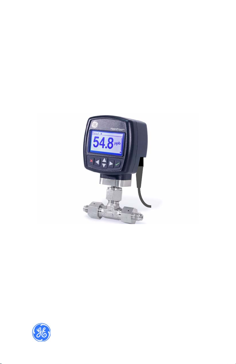
Introduction
The GE Sensing HygroTrace is a compact moisture transmitter
designed for measuring ultra-low water content in the ultra high
purity and semiconductor markets and related applications. The
HygroTrace measures water content in nitrogen or argon gas in
the range of 0 to 100 ppb
calibrated range. The unit features an integrated display and a sixbutton keypad, and is housed in an aluminum enclosure. The
HygroTrace operates on 24 VDC and provides 4-20 mA analog
and RS485 digital outputs.
The HygroTrace uses an aluminum oxide sensor manufactured
with semiconductor techniques. The patented measurement
technique enables the HygroTrace to respond very quickly to
both dry-to-wet and wet-to-dry situations. The technique applies
a temperature pulse to ‘dry’ the sensor. Then, the re-adsorption
rate is measured while holding a constant sensor temperature.
This measurement is proportional to the moisture concentration
in the sample gas. As a result, the HygroTrace offers the
sensitivity and response time needed to effectively measure parts
per billion levels of moisture.
with trending analysis beyond the
v
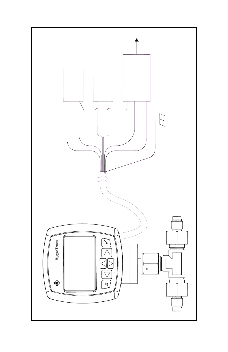
Installation
Sample System Guidelines
The HygroTrace transmitter is typically installed in a sample
system or on the bypass stream of an ultra-high purity gas
distribution system. The factory recommends that the unit be
installed in a sample system to protect the sensor from coming in
contact with damaging elements in the process, and to allow the
transmitter to be removed for service without interrupting the
main process gas flow.
Before constructing a sample system, consult a GE Sensing
applications engineer and adhere to the guidelines below. See
Figure 1 on page 2 for an example of a sample system.
HygroTrace Moisture Transmitter 1
Page 7

September 2007
Sample System Guidelines (cont.)
• A sample system should be kept very simple. It should
contain as few components as possible and all or most of
those components should be located downstream of the
measurement location.
• Sample system components should not be made of material
that will affect measurement. Most common filters and
pressure regulators are not suitable for sample systems
because they have wetted parts that may adsorb or release
moisture, etc. into the sample system. They may also allow
ambient contamination to enter the sample system. If
possible, use stainless steel material for all wetted parts.
• The transmitter should be installed perpendicular to the
sample inlet. For dimensions and other requirements see
Specifications on page 26.
Note: A typical sample system for the hygrometer will use VCR
components.
Note: At least 5 feet of 1/4” tubing, if vented to the atmosphere,
should be installed on the outlet to prevent back diffusion
of ambient moisture into the sample tee cell of the
HygroTrace.
• Sample systems should be leak-tested prior to operation to
verify the integrity of the connections, components and
fittings. Tighten any loose fittings.
IMPORTANT: Caution must be taken when pressurizing or
depressurizing the sample system to prevent
damage to the moisture sensor.
Figure 1: Sample System Example
2 HygroTrace Moisture Transmitter
Page 8

September 2007
Insertion into the Sample System/Process
!CAUTION!
If the HygroTrace is being installed directly into
the process line, consult the factory for proper
installation instructions and precautions before
beginning the following procedure.
!CAUTION!
No maintenance of the sensor can be performed in the
field. Accessing the sensor chamber will break the VCR
seal and should be done only at the factory.
To install the transmitter, refer to Figure 2 below and use a
wrench to thread the female 1/4” fittings of the sample system or
process line onto the 1/4” male VCR fittings of the tee sample
cell configuration.
1/4” VCR (Male)
2 places
Tee Sample Cell
Figure 2: HygroTrace Installation
HygroTrace Moisture Transmitter 3
Page 9
September 2007
Standard Wiring Connections
Note: The HygroTrace is not certified for use in Hazardous
(Classified) locations.
This procedure is for those units not connected to a computer.
The transmitter must be wired using the factory-supplied cable
(two meters in length). If an alternate length is required, please
contact the factory for assistance.
Note: If cables need to be lengthened, r efer to Table 1 on page 5
to splice an extension onto the existing cable. Connect
positive to positive and negative to negative.
Use the following steps to wire the transmitter to the system.
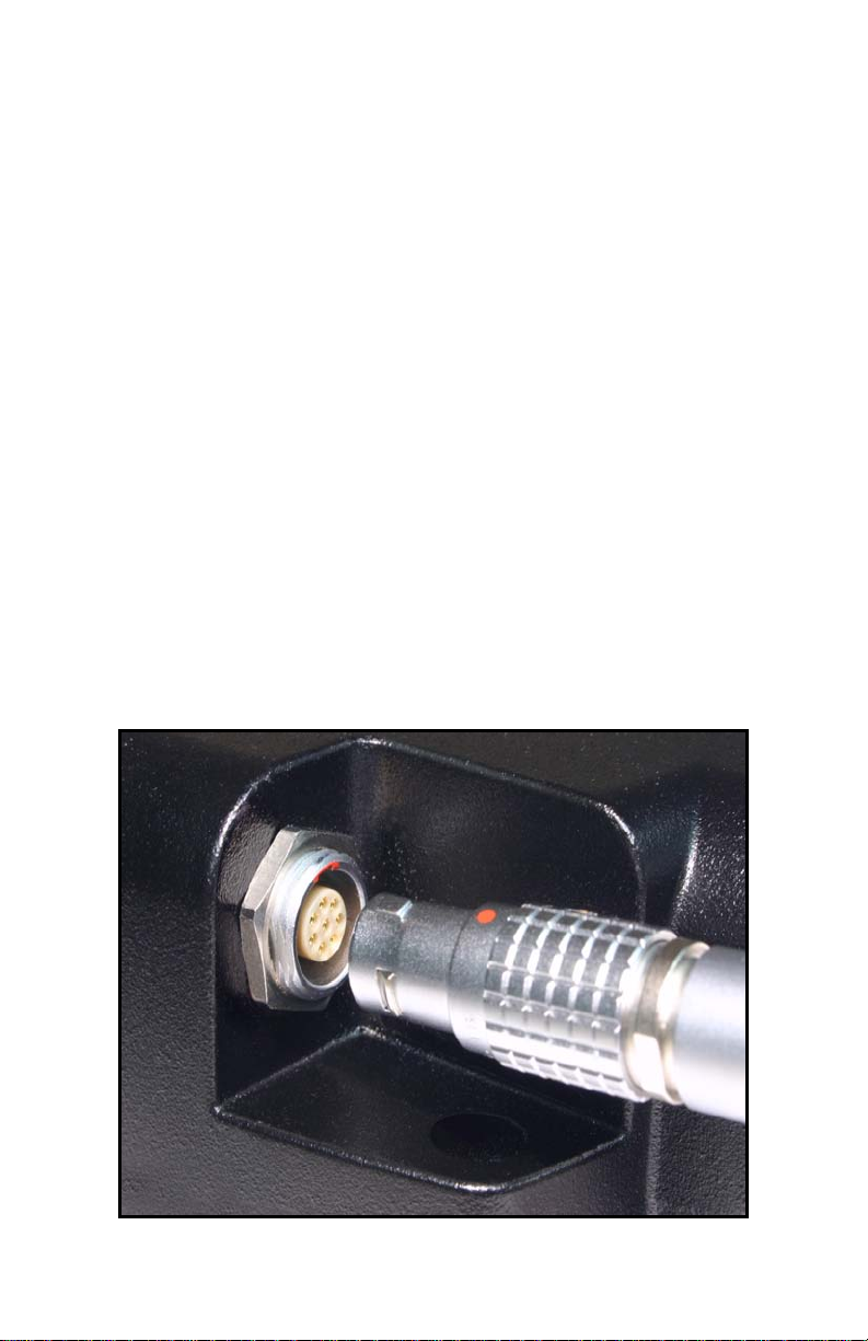
1. Align the red dot with the red mark (see Figure 3 below) and
push the connector on the transmitter cable into the mating
connector on the transmitter module. Make sure the pins are
properly aligned. Once it is inserted, push the cable connector
until it locks into place.
Figure 3: Transmitter Cable Connection
4 HygroTrace Moisture Transmitter
Page 10
September 2007
Standard Wiring Connections (cont.)
2. Using the flying leads at the other end of the transmitt er cable,
connect the transmitter to the power supply and data
acquisition system (DAS) as shown in Figure 4 on page 6.
Refer to Table 1 below for a description of the leads in the
factory-supplied cable.
Table 1: Cable Lead Connections - No PC
Lead Connection Description
Red (+) 24VDC 1 AMP
Black (–) 24VDC 1 AMP
Orange (+) 4-20mA Output
Blue (–) 4-20mA Output
Cable Braid System Ground
3. Trim any unused leads back to the outer cable jacket in order
to remove the bare tinned wire and prevent accidental short
circuits.
The HygroTrace is now ready for operation.
Note: To remove the probe cable, pull back the spring-loaded
sleeve and pull the cable out of the connector.
HygroTrace Moisture Transmitter 5
Page 11
September 2007
+24V 1 AMP
+
RS232
TO PC
RS232
RS485 TO
CONVERTER
POWER
SUPPLY
–
+
4-20mA
METER
–
COMMON
+ RS485
– RS485
SYSTEM
GROUND
RED
BLACK
ORANGE
BLUE
WHITE
GREEN
BRAID
CABLE
Figure 4: Standard Wiring Connections (ref. dwg #702-684)
6 HygroTrace Moisture Transmitter
Page 12

September 2007
Digital Communications Wiring Connections
If the unit is to be operated using PanaView™ instrumentation
software installed on a computer, an RS232/RS485 converter
must be used and the wiring must be set up as follows.
The transmitter must be wired using the factory-supplied cable
(two meters in length).
Note: To lengthen cables, refer to Table 2 below to splice an
extension onto the existing cable. Connect positive to
positive, negative to negative, and ground to ground.
Note: EMI ferrite shielding may be required for communication
through an ungrounded serial port. Please consult the
factory for guidance.
Use the following steps to wire the transmitter to the system.
1. Align the red dot with the red mark (see Figure 3 on page 4)
and push the connector on the transmitter cable into the
mating connector on the transmitter module. Make sure the
pins are properly aligned. Secure the connectors by pushing
the cable connector until it locks in place.
2. Using the flying leads at the other end of the transmitt er cable,
connect the transmitter to the power supply, the data
acquisition system (DAS) and the computer as shown in
Figure 4 on page 6. Refer to Table 2 below for a description of
the leads in the factory-supplied cable.
Table 2: Cable Lead Connections - with PC
Lead Connection Description
Red (+) 24VDC 1 AMP
Black (–) 24VDC 1 AMP
Orange (+) 4-20mA Output
Blue (–) 4-20mA Output
White (+) RS485
Green (–) RS485
Cable Braid System Ground
HygroTrace Moisture Transmitter 7
Page 13

September 2007
Digital Communications Wiring Connections (cont.)
3. Trim any unused leads back to the outer cable jacket in order
to remove the bare tinned wire and prevent accidental short
circuits.
The HygroTrace is now ready for operation.
Note: To remove the probe cable, pull back the spring-loaded
sleeve and pull the cable out of the connector.
Powering Up
After the HygroTrace is wired as described in the previous
sections, power may be applied to the unit. The transmitter takes
up to 60 seconds to initialize and begin normal operation. If the
sensor has been exposed to ambient conditions of less than
10% RH for less than 72 hours, the HygroTrace will meet its
specified accuracy within 24 hours following startup.
8 HygroTrace Moisture Transmitter
Page 14

Using the HygroTrace
Keypad Features
September 2007
Cancel
Left
Figure 5: HygroTrace Keypad
The HygroTrace has only six keys: four arrow keys, a Cancel
key and an Enter key.
Use the arrow keys to navigate among menu choices, and to
increment/decrement numeric entries.
Use the Cancel key to cancel a numeric entry change, or exit
a menu.
Use the Enter key to accept a numeric entry or select a menu
option.
Up
Down
Enter
Right
HygroTrace Moisture Transmitter 9
Page 15

September 2007
The Default Display
Figure 6 on page 11 shows the normal, default display of the
HygroTrace/TFM.
• Menu Prompt Area - Titles, prompts, status displayed here.
• Measurement - 3 ½ digits (0 - 1999). Automatic decimal
placement based on range.
• Unit Symbol - ppb = Parts Per Billion water by volume.
• Keypad Lock Indicator - Unlock sequence required to modify
settings.
• Measurement Progress Bar - HygroTrace takes
~2 minutes to acquire data and complete the measurement.
The progress bar gives a visual indication of the measurement
status.
• Warning/Error Indicator - In the absence of an error, this
region is blank. Errors that effect the quality of the
measurement (e.g. heater failure) are indicated in ALL
CAPITAL letters. Warnings that indicate problems detected
with the measurement are indicated in Mixed Case letters.
Refer to Table 3 below.
Table 3: Warning/Error Messages
No. Label Type Description
0 Status OK ---- No Errors detected.
The calculated PPBv value is greater
Sns Ovr Rng
3
12 Acquiring... WARN
101 HTR FAIL LO ERROR
102 HTR FAIL HI ERROR The heater exceeded 200°C.
Sns Too Wet
204
10 HygroTrace Moisture Transmitter
WARN
WARN
than the highest calibration point,
and is an extrapolation.
Displayed at startup while the
HygroTrace collects data for the first
measurement.
The heater failed to reach the desired
temperature in the time allotted.
The sensor is exposed to excessive
moisture conditions.
Page 16

September 2007
Menu Prompt Area
Measurement
Units Symbol
Warning/Error Indicator
Measurement
Progress Bar
Keypad Lock
Indicator
Figure 6: Default Display
Unlocking the Keypad
After power-on, the HygroTrace keypad is locked. It is necessary
to enter the keypad unlock sequence to make any changes to the
HygroTrace.
Similar to a mobile phone, the HygroTrace will prompt the
operator to unlock if any key is pressed. A passcode is required to
use certain factory service features only.
To unlock the keypad, press Cancel , Enter , Cancel in
sequence.
Accessing the Menus
After successfully unlocking the keypad, the HygroTrace will
display the Main Menu (see Figure 7 on page 12). Use the arrow
keys to highlight the menu item desired. Refer to the Menu Map,
Figure 9 on page 23.
Press Enter to select the highlighted item. Many menu items
will display another menu. Use Cancel to return to the
previous menu page. Pressing Cancel from the Main Menu
will return the screen to the Measurement Display.
HygroTrace Moisture Transmitter 11
Page 17

September 2007
Accessing the Menus (cont.)
Note: Menu items displayed with an ellipsis (…) will bring up
more choices, while those without take immediate action.
Figure 7: Main Menu
Entering Numeric Values
Since the HygroTrace has no numeric keypad, numeric values
are entered using a “combination lock” style of entry:
Use the left arrow key and right arrow key to select the
digit to change. The digit selected will be indicated with a .
Use the up arrow key and down arrow key to increment
or decrement the digit.
Note: If incrementing or decrementing a digit would cause the
numeric value to exceed its allowable range (maximum/
minimum value), the digit will not change.
Press Enter to save the new value and return, or Cancel to
return, leaving the original value intact.
Figure 8: Numeric Entry
12 HygroTrace Moisture Transmitter
Page 18

September 2007
Setting Up the Transmitter
After proper installation, the HygroTrace Transmitter can be set
up to accommodate the user’s requirements. Typically, the user
may need to configure the analog outputs, trim the analog
outputs, and program the digital outputs. Refer to the Menu Map,
Figure 9 on page 23, and complete the following steps. Upon
startup, the HygroTrace proceeds through several displays until a
screen similar to the following appears:
The symbol in the lower right corner
indicates that the screen is locked.
To unlock the screen, press
Cancel, Enter, Cancel.
Note: In most instances; use the Enter key to save an entry and/
or move ahead to the following screen; use the Cancel key
to reject an entry and/or return to the previous screen.
9
Display
When the screen is unlocked, the
Main Menu appears with several
options. To set up the display, select
Display... and press Enter. The
following screen appears:
To show the primary ppb
select Measurement and press
Enter. A screen similar to the
following appears:
Press Cancel to return to the Main
Menu.
display,
v
Diagnostics - has limited access. The service passcode is
required. For a description, see Diagnostics on page 29.
HygroTrace Moisture Transmitter 13
Page 19

September 2007
4-20 Analog Output and Error Reporting
The HygroTrace has a single 4-20 mA analog (recorder) output.
Normally, the output reports the measurement in ppb
user-specified range. The default range is 0-100 ppb
that is, 4 mA represents the zero (0 ppb
the span (100 ppb
The recorder output can exceed this range, within limits. A
measurement greater than the span will be reported up to
20.5 mA, and a reading below the zero will be reported down to
3.8 mA. Faults are indicated by readings outside this range.
) value.
v
), and 20 mA represents
v
using a
v
;
v
These faults will be indicated by a 3.5 mA signal
:
• No Data - transmitter has not completed a measurement cycle,
so it cannot report.
• No Calibration - transmitter was not programmed with
calibration data.
• Out of Range - measurement cannot be determined with the
given calibration.
These faults will be indicated by a 21.1 mA signal
:
• Heater Fail Low - heater failed to reach the operating setpoint.
• Heater Fail High - heater exceeded its operating limit.
Limits are taken from the NAMUR Recommendation NE 043.
Measurement is valid from 3.8 mA to 20.5 mA.
Fault is indicated by ≤3.6 mA or ≥21.0 mA.
The HygroTrace has a special operating mode used to dry the
sensor (see Sensor Dry Down on page 19). When in Dry Down
mode, the unit will report a fixed output of 20.5 mA, the
maximum valid measurement. When returned to normal
operation, the output returns to reporting the actual measurement.
In the case of a measurement exceeding the maximum calibration
value, the output will be limited to the maximum valid signal,
20.5 mA. The HygroTrace will never produce a negative reading
(less than 0 ppb).
14 HygroTrace Moisture Transmitter
Page 20
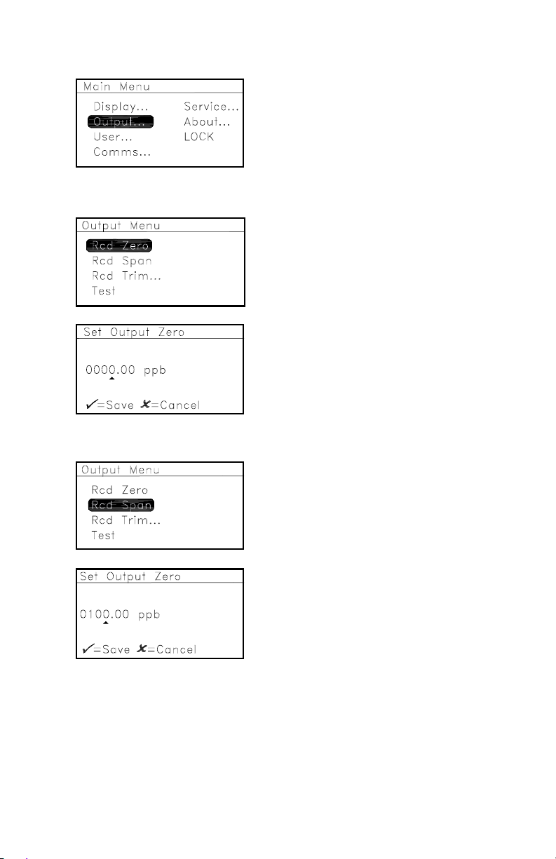
Outputs
Recorder Zero
September 2007
To set up outputs, from the Main
Menu select Output... and press
Enter. The following screen
appears:
To specify the ppb reading
equivalent to 4 mA, select Rcd Zero
and press Enter. A screen similar to
the following appears:
Use the arrow keys to change the
output value. Press Enter to save (or
Cancel to keep the previous value),
and return to the Output Menu.
Recorder Span
To specify the ppb reading
equivalent to 20 mA, select Rcd
Span and press Enter. A screen
similar to the following appears:
Use the arrow keys to change the
output value. Press Enter to save (or
Cancel to keep the previous value),
and return to the Output Menu.
HygroTrace Moisture Transmitter 15
Page 21

September 2007
Recorder Trim
To adjust/calibrate the 4-20 mA
output, select Rcd Trim... and press
Enter. The following screen
appears:
To return an adjusted 4-20mA
calibration to the factory defaults,
press Enter. The following screen
appears.
Note: Resetting the Trim erases any previous values before
calibrating the output.
Select YES or NO and press Enter, or
press Cancel. If you select NO or
press Cancel, the unit returns to the
previous screen and no change is
made to the 4-20mA calibration.
If you select YES, the following screen appears to adjust and
calibrate the 4-20mA signal.
With Trim Zero highlighted, to
adjust the 4 mA output from the
factory default, press Enter and a
screen similar to the following
appears.
Note: The HygroTrace will attempt to output exactly 4.00 mA.
The operator should read the output, in mA, at the DAS or
other indicator, and enter that value as follows.
Use the arrow keys to change the
output value. Press Enter to save (or
Cancel to keep the previous value),
and return to the Recorder Trim
menu.
16 HygroTrace Moisture Transmitter
Page 22

September 2007
Recorder Trim (cont.)
If a new Trim Zero was saved, the
Trim Span is now highlighted. To
adjust the 20 mA output from the
factory default, press Enter and see
a screen similar to the following:
Note: The HygroTrace will attempt to output exactly
20.00 mA. The operator should read the output, in mA, at
the DAS or other indicator, and enter that value in the
following screen.
Use the arrow keys to change the
output value. Press Enter to save (or
Cancel to keep the previous value),
and return to the Recorder Trim
menu. Press Cancel twice to return
to the Main Menu.
Test
To force the 4-20 mA output to a
specified percent of scale, select
Test on the Output Menu and press
Enter. A screen similar to the
following appears.
Use the arrow keys to change the test
value. Press Enter to save (or
Cancel to keep the previous value),
and return to the Output Menu.
Press Cancel to return to the Main
Menu.
HygroTrace Moisture Transmitter 17
Page 23

September 2007
User
PPB Offset
To specify an offset value in PPB
and add to the measured PPB value,
or to dry down the sensor, select
User... on the Main Menu, press
Enter and see the following screen:
Use the arrow keys to enter the user
passcode (2719), press Enter and the
following screen appears. The User
Mode indicator U appears in the
lower right corner of the screen.
T o specify a PPB of fset value, select
PPB Offset, press Enter and the
following screen appears:
U
Use the arrow keys to enter the PPB
offset desired, press Enter and the
screen returns to the User Settings
Menu.
U
Clear PPB Offset
To clear the PPB offset entered
above, select Clear PPB Offset and
press Enter. The following screen
appears. Press Cancel to return to
the Main Menu or proceed to the
U
next option.
Select YES or NO and press Enter, or
press Cancel. If you select NO or
press Cancel, the unit returns to the
previous screen and the PPD offset
is not cleared.
U
If you select YES, the PPB Offset is cleared and the unit returns to
the previous screen.
18 HygroTrace Moisture Transmitter
Page 24

September 2007
Sensor Dry Down
Following factory calibration, the HygroTrace is vacuum
packaged to minimize sensor uptake of ambient moisture during
shipment and storage. Once the unit is installed in the process or
sample system, it is recommended that the user establish a
nominal sample flow of 1 SLM and initiate a manual dry down of
the sensor using the Sensor Dry Down option in the User
Settings Menu.
The initiation of this dry down cycle depends on the exposure of
the unit to ambient moisture conditions. The criteria for exposure
is detailed below . It is recommended that the heater control be set
to 190°C for 24 hours following initial installation. The dry down
cycle must be manually started and stopped by the user.
General rule of thumb: >72 hours @ <10% RH or
>24 hours @ >40% RH
This sensor-drying procedure can be repeated following
prolonged exposure to ambient moisture conditions. This will
ensure the highest accuracy for moisture measurement.
Note: When in Dry Down mode, the unit will report a fixed
output of 20.5 mA, the maximum valid measurement.
When returned to normal operation, the output will return
to reporting the actual measurement.
T o initiate a manual dry down of the
sensor, select Sensor Dry Down in
the User Settings Menu. Press Enter
and the following screen appears:
U
Press Enter to start the Sensor Dry
Down (or press Cancel to not
begin
a sensor dry down cycle) and return
to the previous screen. If you
pressed Enter, the Sensor Dry Down
U
has begun.
Note: The sensor will be heated to and r emain at 190°C until the
user stops this cycle.
HygroTrace Moisture Transmitter 19
Page 25

September 2007
Sensor Dry Down (cont.)
To stop the Sensor Dry Down, select
it again on the User Settings Menu,
press Enter, and this screen appears.
Press Enter to stop the Sensor Dry
Down (or press Cancel to continue)
U
and return to the previous screen.
Note: If you pressed Enter, the Sensor Dry Down has ended.
Communications
Baud Rate
To change the baud rate, select
Comms... on the Main Menu, press
Enter and the following screen
appears:
Select Baud Rate... and press Enter.
A screen similar to the following
appears.
Use the arrow keys to select a new
baud rate and press Enter. The
number at the top right side of the
screen changes. Press Cancel to
return to the Comms Menu.
20 HygroTrace Moisture Transmitter
Page 26

September 2007
Node ID
Note: If more than one HygroTrace is on the RS485 network,
each unit must have a unique ID.
To change the node ID, select Node
ID on the Comms Menu, then press
Enter and the following screen
appears:
Use the arrow keys to change the
node ID value. Press Enter to save
(or Cancel to keep the previous
value), and return to the Comms
Menu.
Test
To test the serial connection over
RS485, select Test and press Enter.
The HygroTrace will transmit a
short message, “HygroTrace Comm
Test - Node 16”, over RS485 for
testing the serial connection.
To return to the Main Menu, press Cancel.
Service - has limited access. The service passcode is required.
For a description of the service menu, see Service on page 30.
HygroTrace Moisture Transmitter 21
Page 27

September 2007
About
To access HygroTrace copyright and software version
information, and instrument data such as unit and sensor serial
numbers, the number of sensor hours and the system uptime:
Select About on the Main Menu
screen and press Enter. The
following screen appears:
+
To access HygroTrace copyright
and serial number information,
select ID on the About HygroTrace
screen and press Enter. A screen
+
similar to the following appears:
To return to the About HygroTrace
menu, press Cancel. To access up
time information, select System
Status and press Enter. A screen
similar to the following appears.
+
To return to the About HygroTrace
menu, press Cancel. T o access
software version information
specific to the unit, select Software
+
Versions and press Enter. A screen
similar to the following appears.
Press Cancel twice to return to the
Main Menu.
+
LOCK
To lock the unit from further
changes, select LOCK on the Main
Menu and press Enter. To restore
access to the unit menus, press
Cancel, Enter, Cancel.
+
22 HygroTrace Moisture Transmitter
Page 28

September 2007
Coeff A
Coeff B
About LOCK
Dump
Update
Params
Service**
Main
User*
57600
Baud Rate
PPB Offset ID
38400
19200
100°C
9600
60°C
50°C
Erase
OFF
150°CHeater Test..
190°C
Resume
Reboot
Cal Data
1200
2400
Reset Trim
Trim Zero
Node ID
Trim Span
Test
Test
Rcd Span
Rcd Trim
Notes:
*User passcode required.
**Service passcode required . Contact factory for assistance.
Display Output Comms
Rcd Zero
Diagnostic**
Figure 9: Menu Map
HygroTrace Moisture Transmitter 23
Page 29

September 2007
Menu Item Descriptions
Display
1. Measurement - Show the primary ppb
display
v
2. Diagnostics - (Service passcode required
)
Output
1. Rcd Zero - Specify the ppb reading equivalent to 4 mA
2. Rcd Span - Specify the ppb reading equivalent to 20 mA
3. Rcd Trim - Adjust/calibrate the 4-20 mA output
a. Reset Trim - Clear trim values prior to recalibrating output
b. Trim Zero - Adjust the 4 mA output
c. Trim Span - Adjust the 20 mA output
4. Test - Force the 4-20 output to a specified percent of scale
User - (User passcode required
)
1. PPB Offset - Enter PPB Offset
2. Clear PPB Offset - Clear PPB Offset
3. Sensor Dry Down - Dry the Sensor
Comms
1. Baud Rate - Specify the data rate for RS485 communications
2. Node ID - Specify the PanaView Network Node ID
3. Test - Force meter to transmit an ID message for test purposes
Service - (Service passcode required
)
1. Update - Update the unit software.
2. Params - Access the parameter storage.
a. Dump - Dump the parameter storage.
b. Erase - Erase the EPROM.
3. Heater Test - Test the heater.
a. 50°C to 190°C - Select the temperature for testing.
b. OFF - Turn the heater off.
c. Resume - Resume normal measurement operation.
24 HygroTrace Moisture Transmitter
Page 30

September 2007
Menu Item Descriptions (cont.)
4. Cal Data - Change the calibration data.
a. Bulk Limit - Set the bulk limit.
b. Cal Curve - Set a calibration point and edit PPB and ZH
values.
c. Extrapolation - Set coefficient A and/or B.
5. Reboot - Reboot and return to the initial screen.
About - Display Product, Copyright, and Version information.
LOCK - Lock the keypad.
HygroTrace Moisture Transmitter 25
Page 31

September 2007
Specifications
General
Measurement Range:
• 0 to 100 ppb
Compatible Gases:
with trend indication beyond the calibrated range
v
• Nitrogen and Argon
Process Gas Temperature Range:
• 14°F to 95°F (–10°C to 35°C)
Storage Temperature:
• –40°F to 158°F (–40°C to 70°C)
Operating Temperature:
• 14°F to 95°F (–10°C to 35°C)
Warm-Up Time:
• Meets specified accuracy within 24 hours, after sensor
exposure <72 hours @ 25°C and 60% RH
Calibrated Uncertainty @ 77°F (25°C):
• ±20% of reading or ±5 ppb
Response Time:
, whichever is greater
v
• Less than 20 min. for 95% of 25 ppb
26 HygroTrace Moisture Transmitter
step change
v
Page 32

Electrical
Power:
• 20 to 28VDC, 20 Watts
Analog Output:
• 4 to 20 mA, 400Ω load max
Digital Output:
• RS485
Output Resolution:
• 14 bits
Display:
• 128 X 64 LED backlit LCD
• Display of primary measurements and diagnostics
Mechanical
September 2007
Sample Connection:
• In-line flow, ¼" male VCR process connection
Sample Flow Rate:
• 1 to 4.3 SCFH (0.5 to 2 SLM)
Operating Pressure:
• 0-10 psig (0 to 0.69 bar)
Proof Pressure:
• 3000 psig (207 bar)
Enclosure:
• Aluminum construction; black color; powder coated finish
• Overall Dimensions (H x W x D): 7.3 in x 4.6 in x 2.5 in
(185 mm x 117 mm x 63.5 mm)
• Weight: 2.5 lbs (1.13 kg)
HygroTrace Moisture Transmitter 27
Page 33

September 2007
Moisture Sensor
Sensor Type:
• Thin-film aluminum oxide moisture sensor
Calibration:
• Each sensor is individually computer-calibrated against known
moisture concentrations.
Calibration Interval:
• Sensor recalibration by GE is recommended every 6 to 12
months depending on the application.
Certification
• Complies with EMC Directive 89/336/EEC and
PED 97/23/EC for DN < 25
• UL 508
Figure 10: Certification Label (for information only)
28 HygroTrace Moisture Transmitter
Page 34

September 2007
Appendix
The Diagnostics and Service menus are intended for factorytrained personnel only, and access is limited by requiring a
service passcode. These menus allow the factory default data,
including calibration data and sensor parameters, to be adjusted.
Please contact an applications or service engineer at GE Sensing
if access to these menus is required. Normal operation of the
HygroTrace does not require access to the information contained
in these menus.
Diagnostics
A Diagnostics Display page can be selected from the Display
Menu (see Figure 11 below), but can be accessed only by using
the service passcode.
= Heating
= Cooling
... = Holding at Temp.
+ = Acquiring Data
= = Calculating Result
Hygrometry
Voltage
Number
of Data
Samples
Heater
Temperature
Menu: x
H:+1.234567 60.2°C
100
N: 85 R :0.855
M:+1.195886e–05
2
Control Status
ppb
Slope
of Fitted Line
Correlation
Coefficient
of Fitted Line
Calculated
Result
Service Mode
Indicator
Figure 11: Diagnostics Display
HygroTrace Moisture Transmitter 29
Page 35

September 2007
!CAUTION!
No maintenance of the sensor can be performed in the
field. Accessing the sensor chamber will break the VCR
seal and should be done only at the factory.
Service
To access the Service Menu, select
Service... on the Main Menu and
press Enter. The following screen
appears:
Use the arrow keys to enter the
Service Passcode. Press Enter and
the following screen appears:
Update
Due to product improvements or software enhancements, it may
be necessary to install new software provided by GE Sensing.
This is done over the RS485 digital communications link, using a
PC application capable of performing an XMODEM file transfer.
Note: For updates, the baud rate setting on the COMMS menu is
ignored. Updates will use the following parameters:
Baud Rate: 38400
Word Size: 8 bits
Stop Bits: 1
Parity: None
Flow Control: None/disabled
To update the instrument software,
select Update on the Service Menu,
press Enter and the following screen
appears:
+
30 HygroTrace Moisture Transmitter
Page 36

September 2007
Update (cont.)
Select YES or NO and press Enter, or
press Cancel. If you select NO or
press Cancel, the unit returns to the
previous screen. If you select YES,
the following screen appears.
+
The HygroTrace software is
updated and the unit reboots (returns
to power up, proceeds through
several initiation displays and
returns to normal operation).
Parameter Storage
Dump
This function transmits the contents of the EEPROM used for
calibration and parameter storage via the RS485 digital link. It is
provided to assist GE Sensing service personnel in maintaining
the product.
To dump the parameter storage,
select Dump, press Enter and the
following message appears at the top
of the screen for a few seconds.
+
When the dump is complete, Param
Storage reappears.
HygroTrace Moisture Transmitter 31
Page 37

September 2007
Erase
Note: Erase will delete ALL calibration and user settings. The
HygroTrace will be incapable of performing accurate
measurements until this data is restored.
Note: This function is provided to assist GE Sensing service
personnel in maintaining the product.
To erase the EPROM, select Erase,
press Enter and the following
message appears at the top of the
screen for a few seconds.
+
Select YES or NO and press Enter, or
press Cancel. If you select NO or
press Cancel, the unit returns to the
previous screen. If you select YES,
the following message appears.
+
When the erasure is complete,
Param Storage reappears. To return
to the Service Menu, press Cancel.
Heater Test
T o perform a test of the heater, select
Heater Test..., press Enter and a
screen similar to the following
appears:
+
Use the arrow keys to select the
appropriate temperature to test, and
press Enter. The temperature in the
upper right corner of the screen
should approximate the one selected.
+
To turn off the test, select OFF and press Enter. The temperature
in the upper right corner of the screen returns to its original value.
To resume normal operation, select RESUME and press Enter.
Press Cancel to return to the Service Menu.
32 HygroTrace Moisture Transmitter
Page 38

September 2007
Calibration Data
T o change the calibration data, select
Cal Data... on the Service Menu,
press Enter and the following screen
appears:
+
Bulk Limit
To set the bulk limit, select it on the
screen and press Enter. The
following screen appears:
+
Use the arrow keys to change to the
desired value and press Enter (or
Cancel to keep the previous value).
The screen returns to the Cal Data
menu.
+
Calibration Curve
To edit the calibration curve, select Cal Curve... on the Cal Data
menu and press Enter. The following screen appears:
To set a calibration point, highlight
Select Cal Point, press Enter and the
following screen appears.
+
Use the arrow keys to enter the
desired calibration point to change
and press Enter (or Cancel to keep
the previous value). The screen
+
returns to Edit Cal Curve.
Proceed in the same way to Edit PPB Value and/or ZH Value to
change the PPB and/or ZH value for a particular calibration point.
Then select the next calibration point and repeat the process.
When Edit Cal Curve is complete, press Cancel to return to the
Cal Data menu.
HygroTrace Moisture Transmitter 33
Page 39
September 2007
Extrapolation
Reboot
To set coefficients A and/or B, select
Extrapolation... and press Enter.
Select the coefficient to change,
press Enter and a screen similar to
the following appears:
+
Use the arrow keys to change to the
desired value and press Enter (or
Cancel to keep the previous value).
The screen returns to the
+
Extrapolation menu. Press Cancel
twice to return to the Service Menu.
T o reboot the meter and return to the
initial screen, select Reboot and
press Enter. The following screen
appears.
+
Select YES or NO and press Enter, or
press Cancel. If you select NO or
press Cancel, the unit returns to the
previous screen. If you select YES, a
reboot occurs.
+
Note: The HygroTrace returns to power up, proceeds through
several initiation displays and returns to normal
operation.
34 HygroTrace Moisture Transmitter
Page 40

USA
1100 Technology Park Drive
Billerica, MA 01821-4111
Web: www.gesensing.com
Ireland
Sensing House
Shannon Free Zone East
Shannon, Co. Clare
Ireland
 Loading...