

Page 1
GE
Sensing
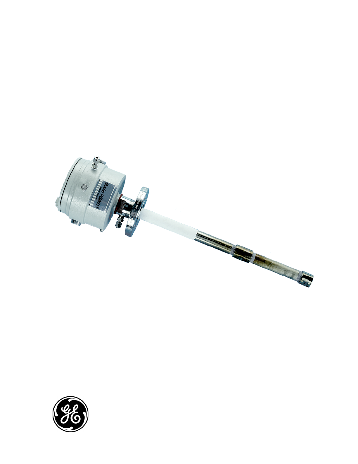
FGA311
Panametrics In Situ Flue Gas Oxygen Analyzer
User’s Manual
910-160C1
March 2006
The FGA 311 In Situ Flue Gas Analyzer is a GE Panametrics product. GE Panametrics has joined other GE
high-technology sensing businesses under a new name—GE Industrial, Sensing.
Page 2

March 2006
Warranty Each instrument manufactured by GE Infrastructure Sensing, Inc. is
warranted to be free from defects in material and workmanship.
Liability under this warranty is limited to restoring the instrument to
normal operation or replacing the instrument, at the sole discretion of
GE Infrastructure Sensing, Inc. Fuses and batteries are specifically
excluded from any liability. This warranty is effective from the date of
delivery to the original purchaser. If GE Infrastructure Sensing, Inc.
determines that the equipment was defective, the warranty period is:
• one year for general electronic failures of the instrument
• one year for mechanical failures of the sensor
If GE Infrastructure Sensing, Inc. determines that the equipment was
damaged by misuse, improper installation, the use of unauthorized
replacement parts, or operating conditions outside the guidelines
specified by GE Infrastructure Sensing, Inc., the repairs are not
covered under this warranty.
The warranties set forth herein are exclusive and are in lieu of
all other warranties whether statutory, express or implied
(including warranties of merchantability and fitness for a
particular purpose, and warranties arising from course of
dealing or usage or trade).
Return Policy If a GE Infrastructure Sensing, Inc. instrument malfunctions within the
warranty period, the following procedure must be completed:
1. Notify GE Infrastructure Sensing, Inc., giving full details of the
problem, and provide the model number and serial number of the
instrument. If the nature of the problem indicates the need for
factory service, GE Infrastructure Sensing, Inc. will issue a RETURN
AUTHORIZATION number (RA), and shipping instructions for the
return of the instrument to a service center will be provided.
2. If GE Infrastructure Sensing, Inc. instructs you to send your
instrument to a service center, it must be shipped prepaid to the
authorized repair station indicated in the shipping instructions.
3. Upon receipt, GE Infrastructure Sensing, Inc. will evaluate the
instrument to determine the cause of the malfunction.
Then, one of the following courses of action will then be taken:
• If the damage is covered under the terms of the warranty, the
instrument will be repaired at no cost to the owner and returned.
• If GE Infrastructure Sensing, Inc. determines that the damage is not
covered under the terms of the warranty, or if the warranty has
expired, an estimate for the cost of the repairs at standard rates
will be provided. Upon receipt of the owner’s approval to proceed,
the instrument will be repaired and returned.
iii
Page 3

March 2006
Table of Contents
Chapter 1: General Information
Introduction. . . . . . . . . . . . . . . . . . . . . . . . . . . . . . . . . . . . . . . . . . . . . . . . . . . . . . . . . . . . . . . . . . . . . . . . . . . . 1-1
Principles of Operation . . . . . . . . . . . . . . . . . . . . . . . . . . . . . . . . . . . . . . . . . . . . . . . . . . . . . . . . . . . . . . . . . 1-3
The Oxygen Sensor . . . . . . . . . . . . . . . . . . . . . . . . . . . . . . . . . . . . . . . . . . . . . . . . . . . . . . . . . . . . . . . . . . . . . 1-3
The Heater Control Circuit . . . . . . . . . . . . . . . . . . . . . . . . . . . . . . . . . . . . . . . . . . . . . . . . . . . . . . . . . . . . . . 1-5
Chapter 2: Installation
Introduction. . . . . . . . . . . . . . . . . . . . . . . . . . . . . . . . . . . . . . . . . . . . . . . . . . . . . . . . . . . . . . . . . . . . . . . . . . . . 2-1
Unpacking the Unit . . . . . . . . . . . . . . . . . . . . . . . . . . . . . . . . . . . . . . . . . . . . . . . . . . . . . . . . . . . . . . . . . . . . . 2-1
Line Power Requirements. . . . . . . . . . . . . . . . . . . . . . . . . . . . . . . . . . . . . . . . . . . . . . . . . . . . . . . . . . . . . . . 2-2
Selecting the Site . . . . . . . . . . . . . . . . . . . . . . . . . . . . . . . . . . . . . . . . . . . . . . . . . . . . . . . . . . . . . . . . . . . . . . . 2-2
Mounting the Analyzer. . . . . . . . . . . . . . . . . . . . . . . . . . . . . . . . . . . . . . . . . . . . . . . . . . . . . . . . . . . . . . . . . . 2-3
Wiring the Analyzer. . . . . . . . . . . . . . . . . . . . . . . . . . . . . . . . . . . . . . . . . . . . . . . . . . . . . . . . . . . . . . . . . . . . . 2-6
Wiring the Line Power . . . . . . . . . . . . . . . . . . . . . . . . . . . . . . . . . . . . . . . . . . . . . . . . . . . . . . . . . . . . . . 2-6
Wiring the Control Signals. . . . . . . . . . . . . . . . . . . . . . . . . . . . . . . . . . . . . . . . . . . . . . . . . . . . . . . . . . . 2-8
Factory Connections. . . . . . . . . . . . . . . . . . . . . . . . . . . . . . . . . . . . . . . . . . . . . . . . . . . . . . . . . . . . . . . . 2-9
Reference Air and Calibration Gas Lines . . . . . . . . . . . . . . . . . . . . . . . . . . . . . . . . . . . . . . . . . . . . . . . . . 2-9
Chapter 3: Operation and Programming
Introduction. . . . . . . . . . . . . . . . . . . . . . . . . . . . . . . . . . . . . . . . . . . . . . . . . . . . . . . . . . . . . . . . . . . . . . . . . . . . 3-1
Preventing Common Problems . . . . . . . . . . . . . . . . . . . . . . . . . . . . . . . . . . . . . . . . . . . . . . . . . . . . . . . . . . 3-1
Powering Up . . . . . . . . . . . . . . . . . . . . . . . . . . . . . . . . . . . . . . . . . . . . . . . . . . . . . . . . . . . . . . . . . . . . . . . . . . . 3-2
Taking Measurements . . . . . . . . . . . . . . . . . . . . . . . . . . . . . . . . . . . . . . . . . . . . . . . . . . . . . . . . . . . . . . . . . . 3-3
Data Records . . . . . . . . . . . . . . . . . . . . . . . . . . . . . . . . . . . . . . . . . . . . . . . . . . . . . . . . . . . . . . . . . . . . . . . . . . 3-3
Menu Map . . . . . . . . . . . . . . . . . . . . . . . . . . . . . . . . . . . . . . . . . . . . . . . . . . . . . . . . . . . . . . . . . . . . . . . . . . . . . 3-3
Programming Options . . . . . . . . . . . . . . . . . . . . . . . . . . . . . . . . . . . . . . . . . . . . . . . . . . . . . . . . . . . . . . . . . . 3-3
Programming with Manual Switches . . . . . . . . . . . . . . . . . . . . . . . . . . . . . . . . . . . . . . . . . . . . . . . . . . . . 3-4
Description of Switches and LEDs . . . . . . . . . . . . . . . . . . . . . . . . . . . . . . . . . . . . . . . . . . . . . . . . . . . 3-5
Manual Programming Instructions . . . . . . . . . . . . . . . . . . . . . . . . . . . . . . . . . . . . . . . . . . . . . . . . . . 3-6
Programming from a Computer Terminal. . . . . . . . . . . . . . . . . . . . . . . . . . . . . . . . . . . . . . . . . . . . . . . . 3-8
RS232 Serial Port Settings. . . . . . . . . . . . . . . . . . . . . . . . . . . . . . . . . . . . . . . . . . . . . . . . . . . . . . . . . . . 3-9
The OPTS Menu. . . . . . . . . . . . . . . . . . . . . . . . . . . . . . . . . . . . . . . . . . . . . . . . . . . . . . . . . . . . . . . . . . . . . 3-9
Trim Menu . . . . . . . . . . . . . . . . . . . . . . . . . . . . . . . . . . . . . . . . . . . . . . . . . . . . . . . . . . . . . . . . . . . . . . . . 3-11
Extra Menu. . . . . . . . . . . . . . . . . . . . . . . . . . . . . . . . . . . . . . . . . . . . . . . . . . . . . . . . . . . . . . . . . . . . . . . . 3-12
Chapter 4: Calibration
Introduction. . . . . . . . . . . . . . . . . . . . . . . . . . . . . . . . . . . . . . . . . . . . . . . . . . . . . . . . . . . . . . . . . . . . . . . . . . . . 4-1
Recommended Calibration Gas . . . . . . . . . . . . . . . . . . . . . . . . . . . . . . . . . . . . . . . . . . . . . . . . . . . . . . . . . 4-1
Measuring the Calibration Response . . . . . . . . . . . . . . . . . . . . . . . . . . . . . . . . . . . . . . . . . . . . . . . . . . . . 4-2
The Calibration Gas System. . . . . . . . . . . . . . . . . . . . . . . . . . . . . . . . . . . . . . . . . . . . . . . . . . . . . . . . . . . . . 4-2
Calibrating the Oxygen Sensor . . . . . . . . . . . . . . . . . . . . . . . . . . . . . . . . . . . . . . . . . . . . . . . . . . . . . . . . . . 4-4
Calibrating with the Manual Switches. . . . . . . . . . . . . . . . . . . . . . . . . . . . . . . . . . . . . . . . . . . . . . . . 4-4
Calibrating with a PC Connection. . . . . . . . . . . . . . . . . . . . . . . . . . . . . . . . . . . . . . . . . . . . . . . . . . . . 4-5
Resume Operation . . . . . . . . . . . . . . . . . . . . . . . . . . . . . . . . . . . . . . . . . . . . . . . . . . . . . . . . . . . . . . . . . . . . . 4-6
v
Page 4

March 2006
Table of Contents (cont.)
Chapter 5: Troubleshooting
Introduction . . . . . . . . . . . . . . . . . . . . . . . . . . . . . . . . . . . . . . . . . . . . . . . . . . . . . . . . . . . . . . . . . . . . . . . . . . . 5-1
Troubleshooting Guide . . . . . . . . . . . . . . . . . . . . . . . . . . . . . . . . . . . . . . . . . . . . . . . . . . . . . . . . . . . . . . . . . 5-1
Sensor/Heater Wiring . . . . . . . . . . . . . . . . . . . . . . . . . . . . . . . . . . . . . . . . . . . . . . . . . . . . . . . . . . . . . . . . . . 5-3
Temperature Problems . . . . . . . . . . . . . . . . . . . . . . . . . . . . . . . . . . . . . . . . . . . . . . . . . . . . . . . . . . . . . . . . . 5-3
ER2 Error Code . . . . . . . . . . . . . . . . . . . . . . . . . . . . . . . . . . . . . . . . . . . . . . . . . . . . . . . . . . . . . . . . . . . . . 5-4
ER3 Error Code . . . . . . . . . . . . . . . . . . . . . . . . . . . . . . . . . . . . . . . . . . . . . . . . . . . . . . . . . . . . . . . . . . . . . 5-5
ER4 Error Code . . . . . . . . . . . . . . . . . . . . . . . . . . . . . . . . . . . . . . . . . . . . . . . . . . . . . . . . . . . . . . . . . . . . . 5-6
Output Problems . . . . . . . . . . . . . . . . . . . . . . . . . . . . . . . . . . . . . . . . . . . . . . . . . . . . . . . . . . . . . . . . . . . . . . . 5-7
All Outputs Inactive. . . . . . . . . . . . . . . . . . . . . . . . . . . . . . . . . . . . . . . . . . . . . . . . . . . . . . . . . . . . . . . . . 5-7
No RS232 Output. . . . . . . . . . . . . . . . . . . . . . . . . . . . . . . . . . . . . . . . . . . . . . . . . . . . . . . . . . . . . . . . . . . 5-8
Oxygen Reading Problems. . . . . . . . . . . . . . . . . . . . . . . . . . . . . . . . . . . . . . . . . . . . . . . . . . . . . . . . . . . . . . 5-9
ER1 Error Code . . . . . . . . . . . . . . . . . . . . . . . . . . . . . . . . . . . . . . . . . . . . . . . . . . . . . . . . . . . . . . . . . . . . . 5-9
Oxygen Percentage Always Reads 20.93 . . . . . . . . . . . . . . . . . . . . . . . . . . . . . . . . . . . . . . . . . . . 5-10
Oxygen Percentage Unchanged for more than 15 Minutes . . . . . . . . . . . . . . . . . . . . . . . . . . 5-11
Oxygen Reading Lower Than Expected . . . . . . . . . . . . . . . . . . . . . . . . . . . . . . . . . . . . . . . . . . . . . 5-11
Oxygen Reading Higher Than Expected. . . . . . . . . . . . . . . . . . . . . . . . . . . . . . . . . . . . . . . . . . . . . 5-11
Chapter 6: Service and Maintenance
Introduction . . . . . . . . . . . . . . . . . . . . . . . . . . . . . . . . . . . . . . . . . . . . . . . . . . . . . . . . . . . . . . . . . . . . . . . . . . . 6-1
Probe Tip Replacement. . . . . . . . . . . . . . . . . . . . . . . . . . . . . . . . . . . . . . . . . . . . . . . . . . . . . . . . . . . . . . . . . 6-1
Cover Removal and Reinstallation. . . . . . . . . . . . . . . . . . . . . . . . . . . . . . . . . . . . . . . . . . . . . . . . . . . . . . . 6-2
Fuse Replacement . . . . . . . . . . . . . . . . . . . . . . . . . . . . . . . . . . . . . . . . . . . . . . . . . . . . . . . . . . . . . . . . . . . . . 6-3
Sensor/Heater Sub-Assembly Replacement . . . . . . . . . . . . . . . . . . . . . . . . . . . . . . . . . . . . . . . . . . . . . 6-5
Removing the Sensor/Heater Sub-Assembly . . . . . . . . . . . . . . . . . . . . . . . . . . . . . . . . . . . . . . . . . 6-5
Installing the Sensor/Heater Sub-Assembly . . . . . . . . . . . . . . . . . . . . . . . . . . . . . . . . . . . . . . . . . . 6-6
Printed Circuit Board Replacement . . . . . . . . . . . . . . . . . . . . . . . . . . . . . . . . . . . . . . . . . . . . . . . . . . . . . . 6-7
Removing the Printed Circuit Board . . . . . . . . . . . . . . . . . . . . . . . . . . . . . . . . . . . . . . . . . . . . . . . . . 6-7
Installing the Printed Circuit Board . . . . . . . . . . . . . . . . . . . . . . . . . . . . . . . . . . . . . . . . . . . . . . . . . . 6-8
EPROM Replacement . . . . . . . . . . . . . . . . . . . . . . . . . . . . . . . . . . . . . . . . . . . . . . . . . . . . . . . . . . . . . . . . . . . 6-9
Spare Parts List . . . . . . . . . . . . . . . . . . . . . . . . . . . . . . . . . . . . . . . . . . . . . . . . . . . . . . . . . . . . . . . . . . . . . . . 6-11
Chapter 7: Specifications
Performance. . . . . . . . . . . . . . . . . . . . . . . . . . . . . . . . . . . . . . . . . . . . . . . . . . . . . . . . . . . . . . . . . . . . . . . . . . . 7-1
Operation. . . . . . . . . . . . . . . . . . . . . . . . . . . . . . . . . . . . . . . . . . . . . . . . . . . . . . . . . . . . . . . . . . . . . . . . . . . . . . 7-1
Functional . . . . . . . . . . . . . . . . . . . . . . . . . . . . . . . . . . . . . . . . . . . . . . . . . . . . . . . . . . . . . . . . . . . . . . . . . . . . . 7-2
Physical . . . . . . . . . . . . . . . . . . . . . . . . . . . . . . . . . . . . . . . . . . . . . . . . . . . . . . . . . . . . . . . . . . . . . . . . . . . . . . . 7-2
Appendix A: The Nernst Equation
Introduction . . . . . . . . . . . . . . . . . . . . . . . . . . . . . . . . . . . . . . . . . . . . . . . . . . . . . . . . . . . . . . . . . . . . . . . . . . . A-1
Equilibrium Conditions. . . . . . . . . . . . . . . . . . . . . . . . . . . . . . . . . . . . . . . . . . . . . . . . . . . . . . . . . . . . . . . . . . A-1
The FGA 311 . . . . . . . . . . . . . . . . . . . . . . . . . . . . . . . . . . . . . . . . . . . . . . . . . . . . . . . . . . . . . . . . . . . . . . . . . . . A-2
vi
Page 5

March 2006
Table of Contents (cont.)
Appendix B: FGA 311 Drawings
Appendix C: CE Mark Compliance
Overview . . . . . . . . . . . . . . . . . . . . . . . . . . . . . . . . . . . . . . . . . . . . . . . . . . . . . . . . . . . . . . . . . . . . . . . . . . . . . . C-1
EMC Compliance . . . . . . . . . . . . . . . . . . . . . . . . . . . . . . . . . . . . . . . . . . . . . . . . . . . . . . . . . . . . . . . . . . . . . . . C-1
LVD Directive. . . . . . . . . . . . . . . . . . . . . . . . . . . . . . . . . . . . . . . . . . . . . . . . . . . . . . . . . . . . . . . . . . . . . . . . . . . C-1
Appendix D: Data Records
General Information . . . . . . . . . . . . . . . . . . . . . . . . . . . . . . . . . . . . . . . . . . . . . . . . . . . . . . . . . . . . . . . . . . . .D-1
User Settings. . . . . . . . . . . . . . . . . . . . . . . . . . . . . . . . . . . . . . . . . . . . . . . . . . . . . . . . . . . . . . . . . . . . . . . . . . . D-1
Test and Calibration Data. . . . . . . . . . . . . . . . . . . . . . . . . . . . . . . . . . . . . . . . . . . . . . . . . . . . . . . . . . . . . . .D-2
Service Record . . . . . . . . . . . . . . . . . . . . . . . . . . . . . . . . . . . . . . . . . . . . . . . . . . . . . . . . . . . . . . . . . . . . . . . . . D-3
vii
Page 6

Chapter 1
Page 7

General Information
Introduction. . . . . . . . . . . . . . . . . . . . . . . . . . . . . . . . . . . . . . . . . . . . . . . . . . . . 1-1
Principles of Operation . . . . . . . . . . . . . . . . . . . . . . . . . . . . . . . . . . . . . . . . . . 1-3
The Oxygen Sensor . . . . . . . . . . . . . . . . . . . . . . . . . . . . . . . . . . . . . . . . . . . . . 1-3
The Heater Control Circuit . . . . . . . . . . . . . . . . . . . . . . . . . . . . . . . . . . . . . . . 1-5
Page 8

March 2006
Introduction The FGA 311 In Situ Flue Gas Oxygen Transmitter monitors the
combustion efficiency of a boiler or furnace by measuring the
percentage of oxygen in the flue gases. This self-contained instrument
is installed so that its zirconium oxide oxygen sensor is located
directly in the stream of the flue gases. The measurements may be
recorded via the built-in 4-20 mA output or transmitted to a computer
terminal via the built-in RS232 interface.
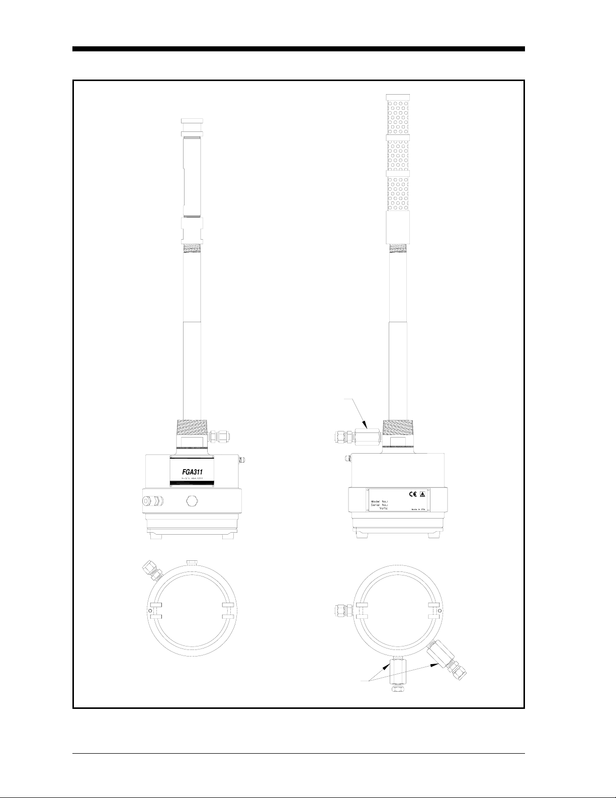
The FGA 311 is available with either the standard weatherproof
enclosure or the optional explosion-proof enclosure, as shown in
Figure 1-1 on page 1-2. However, the operation and the internal
components are the same for both configurations.
The FGA 311 consists of the following sub-assemblies:
• An aluminum enclosure, which includes a breather port, the unit’s
mounting threads, a calibration gas connection and a reference air
connection. In addition, the enclosure houses the printed circuit
board and provides two ports for electrical conduit or cable glands.
• All of the electrical components, including the replaceable fuse,
are mounted on the printed circuit board (PCB). All electrical
connections for the line power, 4-20 mA recorder output and
RS232 interface are made to the PCB.
• A probe assembly that extends into the flue gas stream.
• A heater sub-assembly that maintains the oxygen sensor at the
proper operating temperature for efficient operation.
• A zirconium oxide oxygen sensor to measure the percentage of
oxygen in the flue gases.
• A filter assembly that protects the oxygen sensor from particulates
in the flue gas stream.
The FGA 311 has been designed to permit troubleshooting,
maintenance and adjustment of the instrument without removing the
unit from the flue.
General Information 1-1
Page 9
March 2006
Standard
(Weatherproof)
Explosion-Proof
(Flameproof)
Side Views
Flame Arrestor
R
I
S
R
O
V
U
S
T
T
E
N
S
I
O
N
N
D
E
S
I
G
R
E
N
E
U
O
S
A
P
E
N
D
O
N
O
T
O
P
E
N
E
L
W
I
H
End Views
N
O
D
N
E
P
H
I
W
L
E
N
E
P
O
T
O
A
S
O
U
E
N
E
R
G
I
S
E
D
N
O
I
S
N
E
T
S
U
V
O
R
S
I
R
Flame Arrestors
Figure 1-1: The FGA 311 Enclosures
1-2 General Information
Page 10
March 2006
Principles of Operation In an ideal combustion process, a precise ratio of air to fuel is burned
efficiently to yield only heat, water vapor, and carbon dioxide.
However, because of burner aging, imperfect air to fuel mixtures,
variable firing rates and/or inaccurate ignition timing, this situation
rarely happens.
A sure sign of a less than ideal combustion process is the presence of
excess oxygen in the flue gases. The level of this excess oxygen is
easily monitored with the FGA 311 In Situ Flue Gas Oxygen
Transmitter, and the information can then be used to make the
necessary adjustments to improve the efficiency of the combustion
process. The following two major components are included in the
FGA 311 analyzer:
• a zirconium oxide oxygen sensor
• a loop-controlled heater circuit
These components are described in the sections that follow.
The Oxygen Sensor The inside and outside of the zirconium oxide oxygen sensor are
coated with a porous platinum catalyst, forming two electrodes. Flue
gases flow past the outside of the sensor, while atmospheric air
circulates freely on the inside of the sensor. The atmospheric air is
used as the reference gas for the oxygen measurements. See the
oxygen sensor sub-assembly shown in Figure 1-2 below.
At the normal operating temperature (650° to 1100°C) of the sensor,
the oxygen molecules in the atmospheric reference air (20.93%
oxygen) are electrochemically reduced at the inner electrode. The
resulting oxygen ions seek an equilibrium with the lower oxygen
concentration on the sample gas side of the sensor, by migrating
through the porous ceramic toward the outer electrode.
Packing ScrewSleeveO-Ring
O-Ring Packing Oxygen Cell
Figure 1-2: The FGA 311 Oxygen Sensor
General Information 1-3
Page 11
March 2006
The Oxygen Sensor
(cont.)
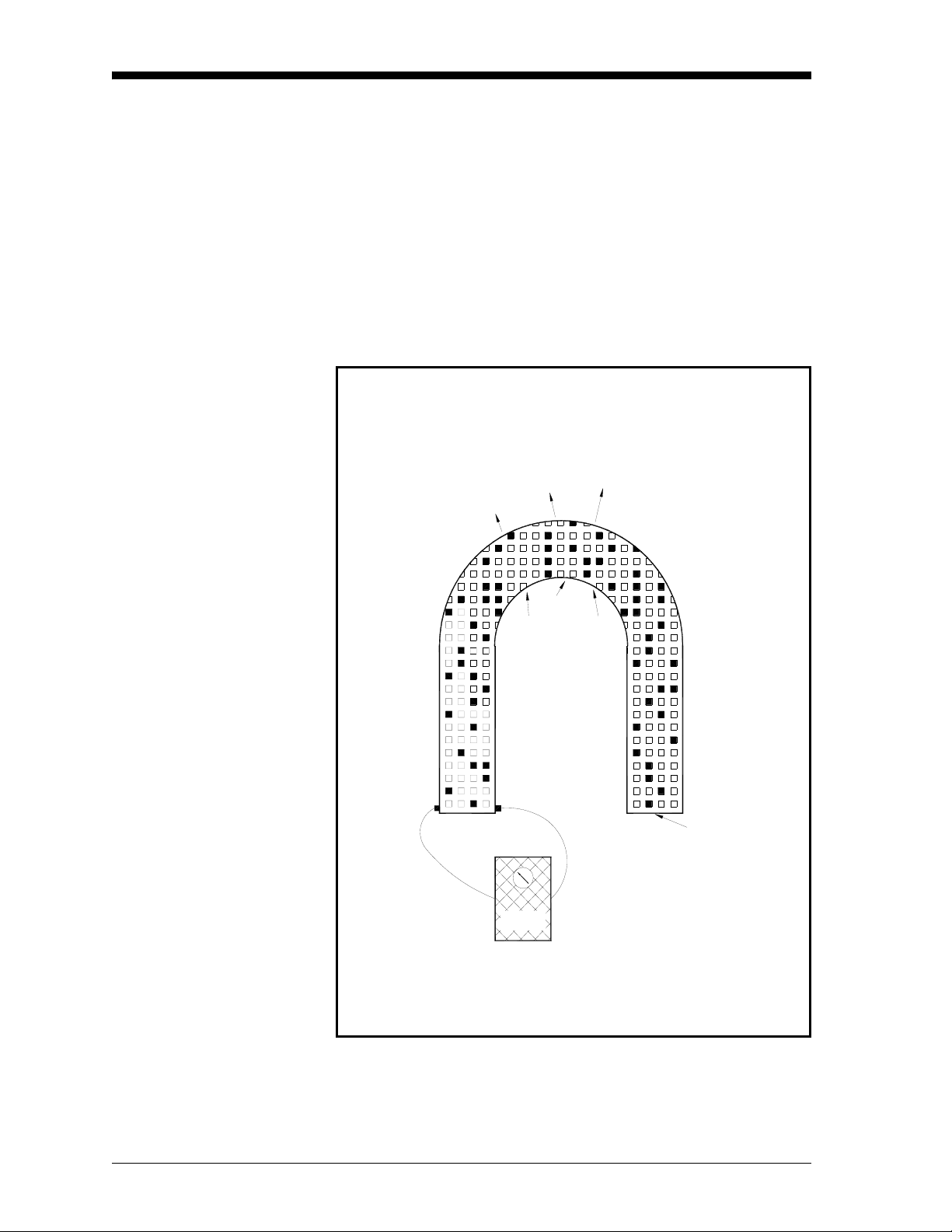
At the outer electrode, the oxygen ions give up their extra electrons
and revert to oxygen molecules, before being swept away by the flue
gas stream. This exchange of electrons at the electrodes generates a
voltage gradient across the sensor. See Figure 1-3 below.
The lower the concentration of oxygen in the flue gases, the greater
the rate of ion migration through the ceramic and the higher the
resulting voltage gradient across the sensor. In fact, the sensor’s
voltage output rises logarithmically as the percentage of oxygen in
the flue gases decreases. This enables the FGA 311 to accurately
measure very small levels of oxygen in the flue gases.
Oxygen ions migrate through the Zirconium Oxide
from Inside to Outside
O
2
O
O
2
2
O
2
O
2
From Outside
Electrode
When O concentration in sample gas falls,
cell voltage rises with increased O migration rate.
Volts
2
O
2
Zirconium Oxide Ceramic
with Lattice Imperfections
From Inside
Electrode
2
Figure 1-3: Oxygen Migration Through the Sensor
1-4 General Information
Page 12

March 2006
The Heater Control Circuit
The oxygen sensor temperature in the FGA 311 is maintained by a
heater, which is part of a complex temperature control loop. This
circuit constantly monitors the oxygen sensor temperature, compares
it to the set point temperature (700°C), and turns the heater ON or
OFF accordingly. The specific type of control circuit used is called a
Proportional Integral Derivative (PID) loop, because of the three
adjustable parameters involved:
• Proportional Band: Because the system cannot respond
instantaneously to temperature changes, the actual temperature of
the oxygen sensor oscillates about the set point. In general,
increasing the proportional band reduces the magnitude of these
temperature oscillations.
• Integral Action: A consequence of increasing the proportional
band is the introduction of an offset between the set point and the
control point. The integral portion of the control loop acts to move
the control point back toward the set point within a specified
period of time. Thus, decreasing this integration time reduces the
offset more quickly.
• Derivative Action: The derivative portion of the control loop
applies a corrective signal based on the rate at which the actual
temperature is approaching the set point. In effect, the derivative
action reduces overshoot by counteracting the control signal
produced by the proportional and integral parameters.
The heater control circuit is configured at the factory for optimum
performance. Because of the strong interaction between the three
parameters involved, properly setting up the PID loop is a very
complex matter. As a result, randomly changing the P, I and/or O
parameters can seriously degrade the performance of the FGA 311.
IMPORTANT: Always contact the factory before attempting to
change the default P, I and/or O values.
General Information 1-5
Page 13

Chapter 2
Page 14

Installation
Introduction. . . . . . . . . . . . . . . . . . . . . . . . . . . . . . . . . . . . . . . . . . . . . . . . . . . . 2-1
Unpacking the Unit . . . . . . . . . . . . . . . . . . . . . . . . . . . . . . . . . . . . . . . . . . . . . 2-1
Line Power Requirements. . . . . . . . . . . . . . . . . . . . . . . . . . . . . . . . . . . . . . . . 2-2
Selecting the Site . . . . . . . . . . . . . . . . . . . . . . . . . . . . . . . . . . . . . . . . . . . . . . . 2-2
Mounting the Analyzer . . . . . . . . . . . . . . . . . . . . . . . . . . . . . . . . . . . . . . . . . . 2-3
Wiring the Analyzer . . . . . . . . . . . . . . . . . . . . . . . . . . . . . . . . . . . . . . . . . . . . . 2-6
Reference Air and Calibration Gas Lines. . . . . . . . . . . . . . . . . . . . . . . . . . . 2-9
Page 15
March 2006
Introduction This chapter gives directions for the proper installation and wiring of
the FGA 311. The following specific topics are included:
• unpacking the unit
• selecting the site
• mounting the analyzer
• wiring the analyzer
!WARNING!
To ensure safe operation of the FGA 311, it must be
installed and operated as described in this manual. In
addition, be sure to follow all applicable local safety codes
and regulations for installing electrical equipment.
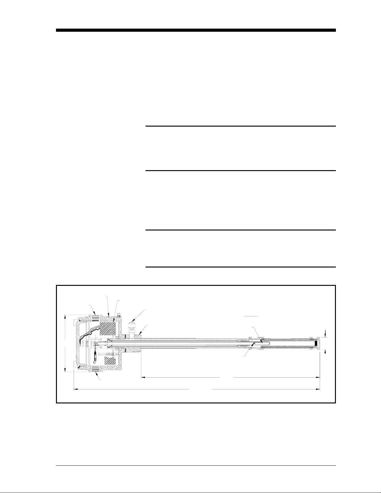
Unpacking the Unit Remove the analyzer from its shipping container and make sure that
all items on the packing slip have been received. If anything is
missing, contact the factory immediately. The analyzer, as shown in
Figure 2-1 below, is shipped fully assembled and ready to install.
3/4" NPT
6"
Enclosure
6
6
5
5
4
4123
123
3/4" NPT
Caution!
When unpacking the analyzer, be careful not to damage
the probe. It is covered with a porous ceramic filter that
will easily crack if it is knocked against a hard surface.
PC Board
Calibration Gas Inlet
1-1/2" NPT
26-1/4"
Heater
19"
Probe
Sensor
Figure 2-1: The FGA 311 In Situ Flue Gas Analyzer
1-1/4"
Installation 2-1
Page 16

March 2006
Line Power Requirements Each FGA 311 analyzer is factory-configured for the proper line
voltage, as specified at the time of purchase. The available options
include the following:
• Japan = 100 VAC
• U.S.A. = 110/120 VAC
• Europe = 220 VAC
• Australia = 240 VAC.
Caution!
To change the line voltage to the unit, contact the factory
for instructions. DO NOT make such a change without first
obtaining proper instructions.
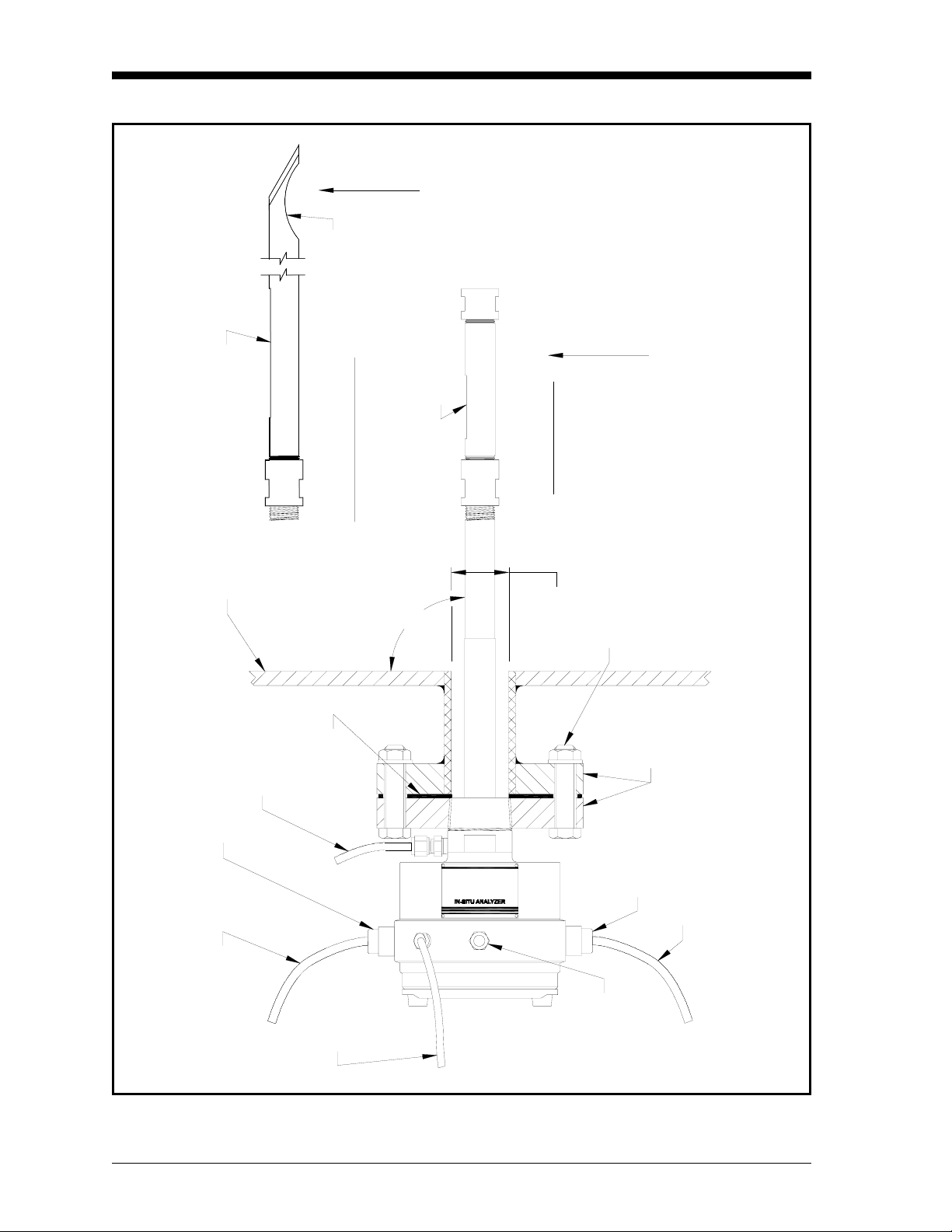
Selecting the Site Environmental and installation factors should already have been
discussed with a GE Sensing applications engineer or field sales
person before the FGA 311 arrives.The analyzer must be installed
either in a furnace or boiler wall or in a flue duct. Ideally, the end of
the probe assembly should extend approximately 1 ft (30.5 cm) into
the flue gas stream. Also, the analyzer should be positioned so that
the probe holes are on the downstream side of the probe (see
Figure 2-2 on page 2-4).
• For furnaces, locate the analyzer close to the combustion zone,
typically within the radiant section and always before the
convection section. Make sure that the probe’s maximum operating
temperature is not exceeded and that the probe is not situated in a
non-homogeneous flue gas mixture.
IMPORTANT: If the ambient temperature in the vicinity of the probe
can exceed 650°C (1202°F), a high temperature
probe assembly is required.
• For boilers, locate the analyzer downstream of the heat exchanger
and just before the economizer air heater, if one is installed. The
analyzer should not be placed downstream of any air heater,
because of possible air leaks that can cause inaccurate readings.
In general, the sample point should be an area of high turbulence,
which will ensure a good homogeneous mixture of the flue gases.
Conditions to be avoided would include air leaks upstream of the
sample point and dead spaces in the vicinity of the sample point.
2-2 Installation
Page 17

March 2006
Mounting the Analyzer The FGA 311 has integral male 1-1/2” NPT mounting threads. This
permits a flange to be threaded onto the analyzer, and the resulting
assembly is then bolted to a mating flange on the furnace/boiler wall
or flue duct.
Note: For installations where the FGA 311 may be exposed to water
or other fluids, install the unit with the breather (see
Figure 2-2 on page 2-4) facing downward.
Do not use any thread sealant during the installation. Upon
heating, Teflon tape will melt and other sealants may emit
gases that interfere with the oxygen readings.
Carefully follow the instructions on page 2-5 to mount the FGA 311
In Situ Flue Gas Oxygen Transmitter. The unit may be mounted in
either a horizontal or vertical orientation.
IMPORTANT: Direct mounting of the FGA 311 into a threaded hole
using its mounting threads is not recommended.
Always use a mounting flange.
To prepare the installation site for mounting the analyzer, complete
the following preliminary steps:
1. Fasten a short section of pipe having at least a 2” inside diameter
into the process wall.
IMPORTANT: Make sure that the pipe is long enough to permit
installation of the flange mounting hardware and that
the flange is oriented with its bolt holes straddling
the vertical and horizontal center lines.
2. Weld a mating flange onto the end of the pipe, as shown in
Figure 2-2 on page 2-4.
Note: Standard available factory options include 3”-300 lb ANSI,
4”-150 lb ANSI and DN80 PN16 mounting flanges. A
separate mating flange can also be supplied with the unit.
Installation 2-3
Page 18
March 2006
GAS
FLOW
Input Scoop
GAS
Holes
Holes
FLOW
Standard Probe
Mounting Wall
Cable Gland
Calibration
1m, 1.5m & 2m Probes
90°
2" Min.
Hardware
Flanges
Gas Line
Gasket
FG311
Cable Gland
Control Cable
Power Cable
Reference
Air Line
Breather
Figure 2-2: Flange Mounting the FGA 311
2-4 Installation
Page 19

March 2006
Mounting the Analyzer
(cont.)
Before mounting the FGA 311 analyzer assembly onto the mating
flange, mark the enclosure in line with the probe holes. Then,
complete the following steps:
IMPORTANT: The probe holes must be positioned on the
downstream side of the probe. See Figure 2-2 on
page 2-4 for the proper orientation.
1. Slide the gasket over the probe assembly and up against the
mounting flange on the analyzer.
Note: Be sure to use a suitable high temperature gasket for this
application.
2. Orient the analyzer so the probe holes are properly positioned on
the downstream side of the probe, and slide the probe through the
hole in the mounting wall until the two flanges meet.
3. Secure the analyzer in place by fitting bolts into the matching
flange mounting holes and fastening the bolts with nuts and
washers. Make sure that the gasket is properly positioned between
the two flanges.
This completes the mounting of the FGA 311. The required external
connections are discussed in the following sections.
Installation 2-5
Page 20

March 2006
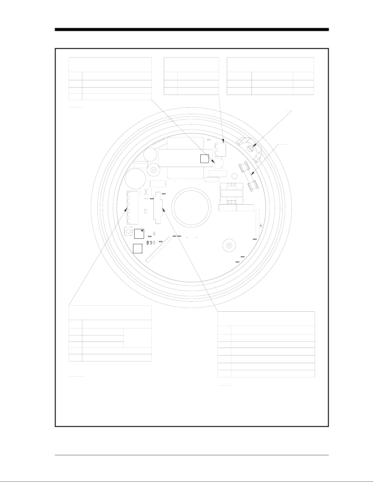
Wiring the Analyzer Connect the power and control signal wiring as described below and
as shown in Figure 2-3 on page 2-7, which shows the printed circuit
board mounted within the open FGA 311 enclosure. The necessary
connectors are supplied with the unit, and they are plugged into the
mating connectors on the printed circuit board prior to shipment. DO
NOT power up the unit until instructed to do so!
ATTENTION EUROPEAN CUSTOMERS!
In order to meet CE Mark requirements, all electrical cables
must be installed as described in Appendix C, CE Mark
Compliance.
Wiring the Line Power Use one of the 3/4” NPT connections on the enclosure for installation
of the power cable gland or conduit. The FGA 311 has been preset at
the factory for the line voltage specified at the time of purchase.
Never connect a different line voltage to the unit without first
obtaining instructions from the factory.
!WARNING!
Improper connection of the power line or connection to the
wrong voltage may result in an electrical hazard.
Note: For compliance with the European Union’s Low Voltage
Directive (73/23/EEC), this unit requires an external power
disconnect device such as a switch or circuit breaker. The
disconnect device must be marked as such, clearly visible,
directly accessible, and located within 1.8 m (6 ft) of the
FGA 311.
The FGA 311 is designed to comply with the LVD Directive
per the requirements of EN 61010 with the following
exception: The 230 VAC unit passes with a test voltage of
1,800 VAC. (Refer to Table D.10 of Annex D in EN 61010.)
Connect the line power to terminal block TB1, as shown in Figure 2-3
on page 2-7, by completing the following steps:
1. Connect the
2. Connect the
LINE (black) lead to pin #1 on TB1.
NEUTRAL (white) lead to pin #2 on TB1.
3. Connect the
GROUND (green) lead to the earth ground screw inside
the enclosure.
Proceed to the next section to wire the control signals.
2-6 Installation
Page 21
March 2006
Heater Connections
J3 Terminal Block
Pin
1
2
3
Description
Heater
No Connection
Heater
NOTE: These connections are made
at the factory.
U15
+
C1
1
E4
TB2
MODE
CAL
S3
ADJ
S1
S2
TB1 Power*
Terminal Block
Description
Pin
1
Line
Neutral
2
Power Voltage Options
Factory Installed
Power Jumpers Fuse
115V W1,W3,W4,W5 1/2A
W2,W6230V 1/4A
*Ground wire goes to
earth gnd connection.
6
7
8
2
3
C1
+
C2
U5
1
3
9
2
1
R
U
V
0
1
E
4
3
R
1
FAULT
10E85
2
1
S
S
D
D
W4
W6 W5
E6
J2
4
E11 E12
S
D
E9
25
3
S
D
J1
W2
1
703-1216
T1
TB1
E3
1
W3
J3
C16
F1
3
L1
4
C15
U18
5
S
D
E7
E2
E1
E5
3
1
5
4
W1
RT1
C14
1
2
Fuse
RS232 Analog Output
TB2 Terminal Block
Pin Description
1Return
2 Receive
3Send
4 4-20 mA Out–
5 4-20 mA Out+
RS232
Thermocouple and Sensor
J2 Terminal Block
Pin
1
Thermocouple +
2
Thermocouple –
3
Zirconium Oxide Oxygen Sensor +
Zirconium Oxide Oxygen Sensor –
4
Description
Future Use (CJC+)5
NOTES:
1. PC Board may be oriented differently,
depending on how the unit is installed.
Future Use (CJC–)6
NOTE: These connections are made
at the factory.
2. J1 is reserved for future use.
(Shown with sensor/heater assembly and cable removed for clarity.)
Figure 2-3: Connections to the FGA 311 PC Board
Installation 2-7
Page 22

March 2006
Wiring the Control Signals Use the remaining 3/4” NPT port on the FGA 311 enclosure for
connecting the control cable gland or conduit. For cable runs of less
than 5 m (16.4 ft), standard twisted pair cable may used for these
connections. However, shielded cable should be used for longer cable
lengths and/or for CE Mark compliance.
IMPORTANT: This symbol indicates Caution - risk of electric
shock:
The control signal connections are made to the printed circuit board
on terminal block TB2, as shown in Figure 2-3 on page 2-7. To make
the necessary connections, complete the following steps:
1. Connect the RS232 serial port leads to TB2 as follows:
Note: The serial port connection should be made with a GE Sensing
#704-668 cable assembly or its equivalent. To assemble an
equivalent cable, refer to Figure B-6 in Appendix B of this
manual.
a. Connect the
Ground lead (the green wire from pin #5 of the
DB9 connector on the PC) to pin #1.
b. Connect the
Receive lead (the red wire from pin #2 of the DB9
connector on the PC) to pin #2.
c. Connect the
Transmit lead (the white wire from pin #3 of the
DB9 connector on the PC) to pin #3.
2. Connect the 4-20 mA analog output leads to TB2 as follows:
a. Connect the 4-20 mA
b. Connect the 4-20 mA
Return (-) lead to pin #4.
Signal (+) lead to pin #5.
Proceed to the next section for a description of the internal, factoryinstalled wiring.
2-8 Installation
Page 23

March 2006
Factory Connections In addition to the user connections described above, the following
connections are made at the factory to terminal blocks J2 and J3.
• Thermocouple connections to J2 on pins #1 (+) and #2 (-).
• Oxygen sensor connections to J2 on pins #3 (+) and #4 (-).
• Heater connections to J3 on pins #1 and #3.
For reference purposes only, these factory connections are shown in
Figure 2-3 on page 2-7.
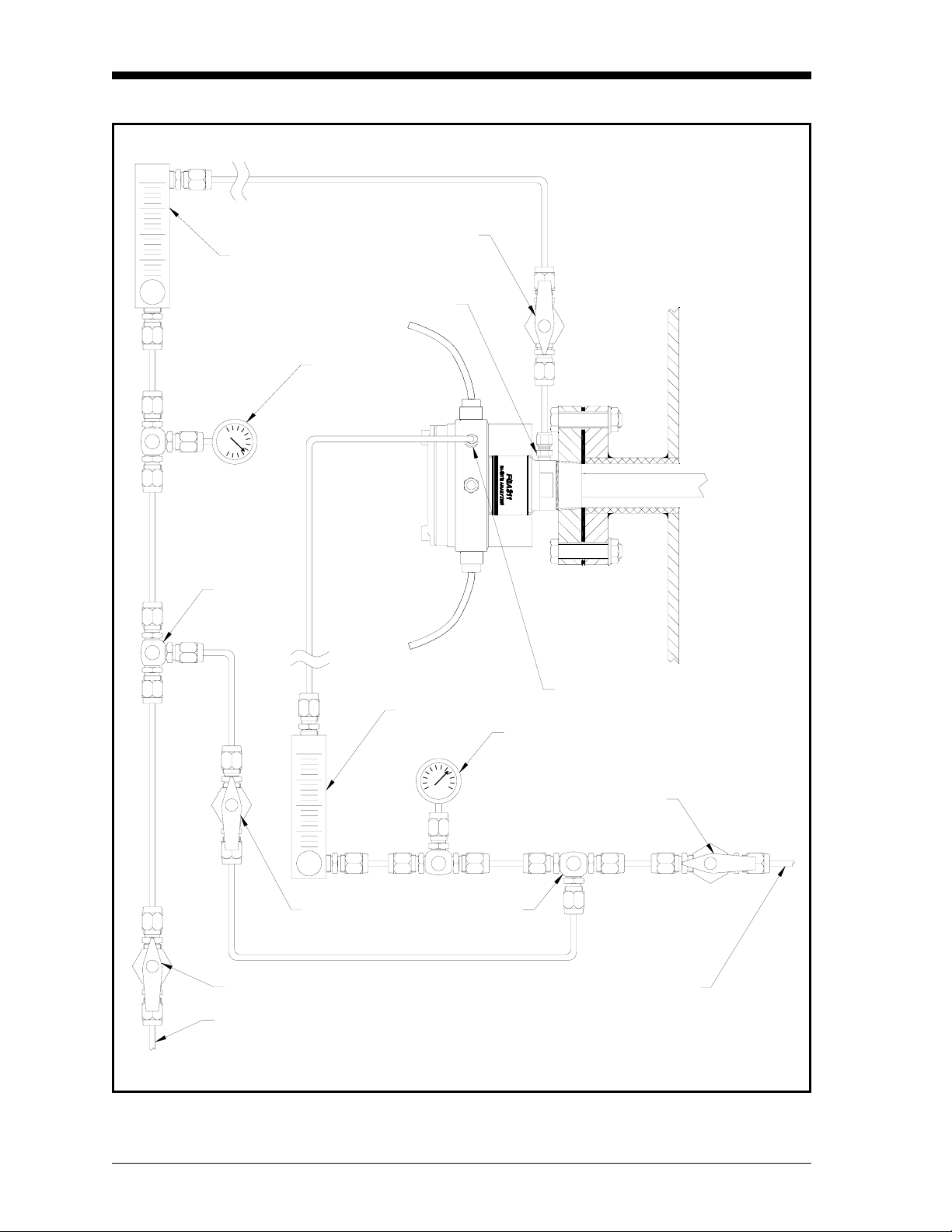
Reference Air and Calibration Gas Lines
During normal operation, the FGA 311 requires a constant supply of a
reference air for the zirconium oxide oxygen sensor. The
recommended gas for this purpose is instrument air (containing
20.93% oxygen) at a flow rate of 20-50 cc/min. Connect this gas
supply, with 1/4” tubing, to the 1/4” compression fitting provided.
Refer to Figure 2-4 on page 2-10 for the location of this connector.
Also, a separate gas supply is required for calibration of the
instrument. This line should be connected, with 1/4” tubing, to the
remaining 1/4” compression fitting on the FGA 311. See Figure 2-4
on page 2-10 for the location of this connector.
Note: The calibration gas port must remain capped, if no permanent
plumbing is attached. See Chapter 4, Calibration, for a
discussion of the recommended calibration gases and
procedures.
In addition to the basic reference air and calibration gas lines, a
variety of ancillary equipment is recommended. A typical system that
will ensure efficient and reliable operation of the FGA 311 is
illustrated in Figure 2-4 on page 2-10.
Installation 2-9
Page 24
March 2006
Valve
Flowmeter
Calibration Gas Inlet
Gauge
Tee
Valve
Valve
Calibration Gas Supply
Reference Air Inlet
Flowmeter
Gauge
Valve
Tee
Reference Air Supply
Figure 2-4: A Typical FGA 311 System
2-10 Installation
Page 25

Chapter 3
Page 26

Operation and Programming
Introduction. . . . . . . . . . . . . . . . . . . . . . . . . . . . . . . . . . . . . . . . . . . . . . . . . . . . 3-1
Preventing Common Problems . . . . . . . . . . . . . . . . . . . . . . . . . . . . . . . . . . . 3-1
Powering Up . . . . . . . . . . . . . . . . . . . . . . . . . . . . . . . . . . . . . . . . . . . . . . . . . . . 3-2
Taking Measurements. . . . . . . . . . . . . . . . . . . . . . . . . . . . . . . . . . . . . . . . . . . 3-3
Data Records. . . . . . . . . . . . . . . . . . . . . . . . . . . . . . . . . . . . . . . . . . . . . . . . . . . 3-3
Menu Map . . . . . . . . . . . . . . . . . . . . . . . . . . . . . . . . . . . . . . . . . . . . . . . . . . . . . 3-3
Programming Options. . . . . . . . . . . . . . . . . . . . . . . . . . . . . . . . . . . . . . . . . . . 3-3
Programming with Manual Switches. . . . . . . . . . . . . . . . . . . . . . . . . . . . . . 3-4
Programming from a Computer Terminal . . . . . . . . . . . . . . . . . . . . . . . . . 3-8
Page 27

March 2006
Introduction Since the FGA 311 In Situ Flue Gas Oxygen Transmitter is a
monitoring device, operation of the installed analyzer is simple. Once
it has been properly installed and set up, it will simply begin taking
readings. However, the analyzer should be allowed to warm up for at
least one hour (three hours if possible) prior to use. See Chapter 2,
Installation, if all of the required installation requirements have not
yet been completed.
Calibration of the unit should be checked once or twice a week for the
first month of operation and once every 2-3 months thereafter. See
Chapter 4, Calibration, for the correct procedures.
!WARNING!
To ensure safe operation of the FGA 311, it must be
installed and operated as described in this manual. In
addition, be sure to follow all applicable local safety codes
and regulations for installing electrical equipment
Preventing Common Problems
Because of the extreme conditions in monitoring flue gases and the
complexity of the FGA 311’s measurement techniques, some simple
precautions should be taken with the instrument. Failure to observe
these basic procedures can lead to operational difficulties.
Compliance with the following instructions will help to eliminate
such common problems:
• Do not use pipe thread compounds on any part of the FGA 311.
Many pipe thread compounds emit combustible vapors that may
cause inaccurate readings.
• Do not handle the sensor assembly any more than is absolutely
necessary. Although some scratches on the platinum electrode can
be tolerated, rubbing the coating should be avoided. Also, the
transfer of skin oils to the electrode can cause erroneous readings.
• Scrubbing the sensor while washing it or washing a hot sensor can
damage or destroy it. Clean the sensor only by rinsing it with clean
water, after the sensor has cooled.
• Installing a cold probe assembly into a hot flue gas stream can
cause damage to the filter and/or sensor. Always allow the probe
assembly to gradually heat up to normal operating temperature,
before subjecting it to hot flue gases.
If any problems not covered in this manual are encountered, contact a
GE Sensing representative for assistance.
Operation and Programming 3-1
Page 28

March 2006
Powering Up Before powering up the unit, start the flow of reference air. Be sure
that the reference air source is connected to the correct port, as shown
in Figure 2-4 on page 2-9. As stated in Chapter 2, Installation, the
recommended reference air is instrument air (20.93% oxygen) at a
flow rate of 20-50 cc/min.
Note: The zirconium oxide oxygen sensor can not provide accurate
readings without a known oxygen percentage on the reference
side of the cell. Allow the reference air to flow for at least five
minutes prior to operation.
Power may now be applied to the unit. Since the FGA 311 does not
have its own power switch, the main disconnect must be used to
power the analyzer on. Simply place this switch in the ON position,
and allow the analyzer to warm up for at least one hour (three hours if
possible) before taking any readings.
Note: For compliance with the European Union’s Low Voltage
Directive (73/23/EEC), this unit requires an external power
disconnect device such as a switch or circuit breaker. The
disconnect device must be marked as such, clearly visible,
directly accessible, and located within 1.8 m (6 ft) of the
FGA 311.
The FGA 311 is designed to comply with the LVD Directive
per the requirements of EN 61010 with the following
exception: The 230 VAC unit passes with a test voltage of
1,800 VAC. (Refer to Table D.10 of Annex D in EN 61010.)
The red fault light (DS4) and one of the green oxygen range
indicators (DS1, DS2 or DS3) on the printed circuit board will blink
until the FGA 311 has reached its normal operating temperature of
700°C. Then, the fault light will go out and the range indicator will
glow steadily.
3-2 Operation and Programming
Page 29

March 2006
Taking Measurements After the FGA 311 has warmed up, the voltage output of the
zirconium oxide oxygen sensor will vary logarithmically with the
oxygen concentration in the flue gases, according to the Nernst
equation (see Appendix A, The Nernst Equation, for details):
20.93
EmV()48.274
In Equation 3-1 above, “E” is the voltage in millivolts generated by
the sensor at an operating temperature of 700°C.
The built-in thermocouple temperature sensor in the FGA 311
automatically adjusts the constant used in the Nernst equation to
reflect the precise actual temperature of the oxygen sensor. In
addition, the non-linear output voltage signal generated by the oxygen
sensor is internally converted into a linear 4-20 mA output current
signal, which is sent to pins 4 and 5 of terminal block TB2. The 4-20
mA current range corresponds to a flue gas oxygen range of 0% to the
programmed O
ammeter or a recording device to these terminals, the oxygen content
of the flue gases may be continuously monitored.
range (5, 10 or 25%). By connecting a digital
2
-------------
log•=
%O
2
(3-1)
Data Records Appendix D, Data Records, at the back of this manual provides
several tables for entering all of the relevant data pertaining to the
installation and programming of the FGA 311. Be sure to maintain
the accuracy of this data on a regular basis. In the event of problems
with the unit, the data records may provide valuable information to
assist in the troubleshooting procedure.
Menu Map A complete menu map of the FGA 311’s built-in software is shown in
Figure 3-3 on page 3-22. Refer to this figure as needed to supplement
the step-by-step programming instructions that follow.
Programming Options The following two methods for programming the FGA 311 In Situ
Flue Gas Oxygen Transmitter may be used to navigate through the
User Program:
• manual switches, which are located inside the enclosure, on the
analyzer’s printed circuit board
• a terminal or computer, utilizing the unit’s built-in RS232 serial
interface
Note: The entire
programming switches.
EXTRA menu is not accessible via the manual
Operation and Programming 3-3
Page 30
March 2006
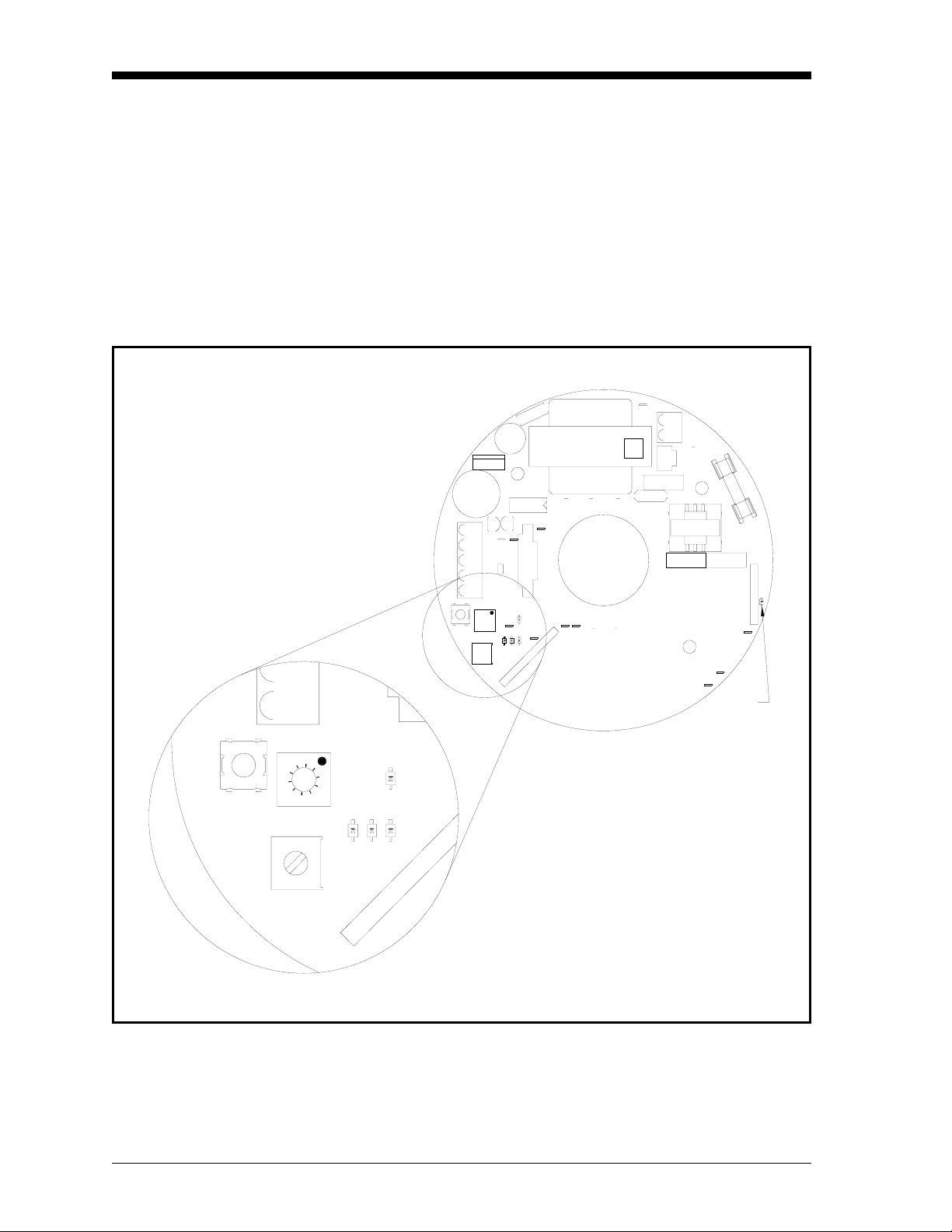
Programming with Manual Switches
CAL
S3
MODE
9
8
7
6
5
4
Manual programming of the FGA 311 is accomplished with a series
of switches and LEDs located on the printed circuit board. These
components, which are shown in Figure 3-1 below, may be accessed
by removing the cover from the FGA 311.
Although the menu map shown in Figure 3-3 on page 3-22 does apply
to both the manual programming mode and the RS232 programming
mode, some of the programming options are not available via the
manual switches. Specifically, the entire EXTRA menu can not
accessed via the PC board switches.
6
78
W2
W1
T1
TB1
E3
1
W3
C14
J3
C16
F1
3
L1
4
C15
U18
E7
E2
E1
E5
3
1
5
RT1
1
2
DS5
0
1
2
3
TB2
S1
5 10
E8
1
FAULT
4
S
D
25
E9
2
3
1
C
U15
+
C2
1
U5
+
C1
1
CAL
S3
TB2
MODE
ADJ
9
2
1
R
U
V
E4
0
1
E
4
3
R
1
S1
FAULT
10E85
25
3
2
1
S
S
S
D
D
D
S2
34
W4
W6 W5
E6
J2
4
E11 E12
S
D
E9
1
J1
703-1216
5
S
D
1
2
3
S
S
S
D
D
S2
D
ADJ
Figure 3-1: Circuit Board Switches and LEDs
3-4 Operation and Programming
Page 31

March 2006
Description of Switches and LEDs
The following switches and lights will be found on the printed circuit
board of the FGA 311:
• MODE Switch S1: a 10-position rotary switch that is used to select
the desired menu option.
• ADJ Switch S2: a rotary encoder switch used to adjust the value of
numeric menu options selected with Switch S1.
• CAL Switch S3: a push-button switch used to enter and exit
programming mode and to confirm the programming option set
with Switch S1.
• DS1-DS3: three green LEDs that are used to indicate the selected
oxygen range setting.
• DS4: a red LED that is used as a fault indicator.
• DS5: a yellow LED that indicates the heater duty cycle.
The specific menu options that may be selected with the 10-position
rotary
MODE Switch S1 are listed in Table 3-1 below.
Table 3-1: MODE Switch S1 Positions
Switch Position Menu Option
0TST
1AIR
2GAS
3RNG
4TRIM_O2 4mA
5 TRIM_O2 20mA
6Not Used
7Not Used
8Not Used
9Not Used
Note: Only six of the ten positions on Switch S1 (0-5) are currently
active. Positions 6–9 are not used at this time.
Navigating through the FGA 311’s built-in User Program software is
easily accomplished by completing the detailed steps in the following
section.
Operation and Programming 3-5
Page 32

March 2006
Manual Programming Instructions
Use the following instructions to program the FGA 311 with the
printed circuit board switches:
Set Switch S1 = 0 Push
CAL Switch S3 and hold for 5
seconds to access the TST option.
The red Fault LED (
DS4) will light
if the sensor is bad, or the three
green LEDs (
DS1-DS3) will light if
the sensor is good. Press Switch S3
and hold for 5 seconds to
EXIT
programming mode.
Set Switch S1 = 1 Push
CAL Switch S3 and hold for 5
seconds to set the AIR calibration.
A green LED will blink until the
calibration is complete. Press
Switch S3 and hold for 5 seconds
to
EXIT programming mode.
IMPORTANT: Always complete the
attempting the
LED may glow temporarily during the
AIR calibration before
GAS calibration. Also, The red fault
GAS
calibration procedure.
Set Switch S1 = 2 Push
CAL Switch S3 and hold for 5
seconds to set the
Adjust the value with
GAS calibration.
ADJ Switch
S2 until a green LED starts
blinking. Press Switch S3 and hold
for 5 seconds to EXIT programming
mode.
Note: Refer to Chapter 4, Calibration, for a detailed description of
the calibration procedures.
Set Switch S1 = 3 Push
CAL Switch S3 and hold for 5
seconds to access the RANGE
option. The current O
range LED
2
will blink. Adjust the value with
ADJ Switch S2 until the green
LEDs start blinking. Press Switch
S3 and hold for 5 seconds to EXIT
programming mode.
3-6 Operation and Programming
Page 33

Manual Programming
Instructions (cont.)
March 2006
Set Switch S1 = 4 Push
CAL Switch S3 and hold for 5
seconds to access the TRIM_O2
4mA option. Adjust the value with
ADJ Switch S2 until the output
signal reads 4 mA. Press Switch
S3 and hold for 5 seconds to EXIT
programming mode.
Note: For the TRIM_O2 function, always adjust the 4 mA setting
before
the 20 mA setting. This will ensure optimum accuracy
of the instrument.
Set Switch S1 = 5 Push
CAL Switch S3 and hold for 5
seconds to access the TRIM_O2
20mA option. Adjust the value
with
ADJ Switch S2 until the
output signal reads 20 mA. Press
Switch S3 and hold for 5 seconds
to EXIT programming mode.
After the programming has been completed, reinstall the cover on the
FGA 311 enclosure. Do not operate the FGA 311 permanently with
the cover removed.
Operation and Programming 3-7
Page 34

March 2006
Programming from a Computer Terminal
In the following instructions, the actual terminal screen display is
shown in the left column, while the required user response is shown
in the right column. Keyboard inputs are indicated by square brackets
(i.e. [ESC] means to press the “escape key” on the keyboard). Also, to
change a displayed numeric value, use the
[+] and [-] keys to adjust the
current value to the desired setting.
For reference, the screen display of a typical menu line is shown in
Figure 3-2 below. This figure pictures the menu line that appears on
the terminal screen, as soon as the User Program has been accessed.
Note the location of the selection brackets, which highlights the
current menu choice.
Menu Choices
TRIM EXTRA[OPTS]
Selection Brackets
Figure 3-2: A Typical Menu Line
Navigating through the User Program is easy, using the keystrokes in
Table 3-2 below and the instructions in the following sections.
Table 3-2: Computer Terminal Keyboard Entries
Desired Action Keyboard Entry
Move from run mode to programming mode [ESC]
Move from programming mode to run mode
Move selection brackets
Enter numerical data
Confirm selection or entry
Start entry over again
Move up one level in program
[ESC]
[SPACE]
, [-]
[+]
[ENTER]
[BACKSPACE]
[BACKSPACE]
Note: The use of any keys on the keyboard other than those listed in
Table 3-2 above will not be recognized by the FGA 311. Any
such keyboard entries will simply be ignored by the analyzer.
[+] is a shifted key, and the [SHIFT] key must be held while
Also,
striking it.
3-8 Operation and Programming
Page 35

March 2006
RS232 Serial Port Settings Before the FGA 311 may be programmed via its built-in RS232
interface, the serial port of the personal computer (PC) must be
configured to the following specifications:
• 9600 Baud
• 8 Data Bits
• 1 Stop Bit
• No Parity
• Xon/Xoff Flow Control
Note: If the RS232 connection still does not work, try reversing the
leads on pins 2 and 3 of terminal block
Refer to the computer’s documentation for the correct procedures to
configure and access the serial port. Then, proceed to the next section
to begin programming the analyzer.
The OPTS Menu Use the following procedure to move through the OPTS menu.
TB2.
RUN 20.93% O2 700.0C Press
Note: While in the
time by pressing the
[OPTS] TRIM EXTRA Make sure
OPTS menu, you may return to run mode at any
[ESC] key.
[ESC] to move from run mode
to the main menu.
OPTS is highlighted and
then press
[ENTER].
Oxygen Sensor Test IMPORTANT: The oxygen sensor test must be done while the
instrument is measuring
[TST] AIR GAS RNG Make sure TST is highlighted and
then press
TEST PASSED xxx.x% One of these two screens will
appear. Press
TEST FAILED xxx.x%
to the
GAS (not AIR).
[ENTER].
[BACKSPACE] to return
OPTS menu.
Press
[ESC] to return to run mode, or proceed to the next section to
continue programming the
Operation and Programming 3-9
OPTS menu.
Page 36

March 2006
Air Measurement
Calibration
TST [AIR] GAS RNG Press [SPACE] to select AIR and
then press
[ENTER].
Gas Measurement
Calibration
AIR 20.93%O2 xxx.xC Press
[ENTER] to accept the new
offset value and
return to the
just press
OPTS menu.
the
[BACKSPACE] to
OPTS menu. To abort,
[BACKSPACE] to return to
Note: Refer to Chapter 4, Calibration, for a detailed description of
the calibration procedures.
[ESC] to return to run mode, or proceed to the next section to
Press
continue programming the
OPTS menu.
TST AIR [GAS] RNG Press [SPACE] to select GAS and
then press
GAS [x.xx]%O2 xxx.xC Adjust the
and
[ENTER].
O2 value with the [+]
[-] keys. Press [ENTER] to
accept the new value and
[BACKSPACE] to return to the OPTS
menu. To abort, just press
[BACKSPACE] to return to the OPTS
menu.
Press [ESC] to return to run mode, or proceed to the next section to
continue programming the
OPTS menu.
Set Oxygen Range
TST AIR GAS [RNG] Press [SPACE] to select RNG and
then press
[O2_RNG] TEMP_RNG Make sure
then press
5% [10%] 25% Press
oxygen range and press
Press
RNG menu.
3-10 Operation and Programming
[ENTER].
O2_RNG is selected and
[ENTER].
[SPACE] to select the desired
[ENTER].
[BACKSPACE] to return to the
Page 37

March 2006
Trim Menu Use the following procedure to move through the TRIM menu.
Trim Oxygen Output
RUN 20.93%O2 700.0C Press
[ESC] to move from run mode
to the User Program.
Note: While in the
time by pressing the
OPTS [TRIM] EXTRA Press
TRIM menu, you may return to run mode at any
[ESC] key.
[SPACE] to select TRIM and
then press
[ENTER].
[TRIM_O2] TRIM_TEMP Make sure TRIM_O2 is highlighted
and press
[ENTER].
Note: For the TRIM_O2 function, always adjust the 4 mA setting
before the
20 mA setting. This will ensure that the instrument
operates at optimum accuracy.
TRIM_O2 mA: [4] 20 Make sure “
then press
4” is highlighted and
[ENTER].
4mA_O2 [xxx] ADJUST Using
[+] and [-], adjust the value
to obtain an output signal of 4 mA.
[ENTER] to accept the new
Press
value. Press
[BACKSPACE] to back
up one menu level.
TRIM_O2 mA: 4 [20] Press
20mA_O2 [xxx] ADJUST Using
[SPACE] to select “20” and
then press
[ENTER].
[+] and [-], adjust the value
to obtain an output signal of 20
mA. Press
new value. Press
[ENTER] to accept the
[BACKSPACE]
twice to return to the
Press
[ESC] to return to run mode, or proceed to the next section to
continue programming the
TRIM menu.
TRIM menu.
Operation and Programming 3-11
Page 38

March 2006
Extra Menu Use the following procedure to move through the EXTRA menu.
RUN 20.93%O2 700.0C Press [ESC] to move from run mode
to the User Program.
Selecting Terminal Type
Note: While in the
time by pressing the
OPTS TRIM [EXTRA] Press
[COM] ERR PID FRZ RESP OFST
[TTY] ANSI Press
EXTRA menu, you may return to run mode at any
[ESC] key.
[SPACE] to select EXTRA and
then press
[ENTER].
Make sure COM is selected and
then press
[SPACE] to select the desired
option and then press
return to the
[BACKSPACE].
[ENTER].
[ENTER]. To
EXTRA menu, press
Note: Select TTY to interface the FGA 311 with a Teletype terminal,
or select ANSI to use a computer terminal that communicates
via the standard ASCII character set. For most modern
personal computers, select the ANSI option.
[ESC] to return to run mode, or proceed to the next section to
Press
continue programming the
EXTRA menu.
3-12 Operation and Programming
Page 39

Error Handling Set Up
March 2006
COM [ERR] PID FRZ RESP OFST
Press [SPACE] to select ERR and
then press
[ENTER].
This sub-menu permits set up of the responses of the FGA 311 to
various error situations. The following error states may be configured
via this menu:
• ER1: the Sensor Failure! error message.
• ER2: the Warning: Warming Up! error message.
• ER3: the Open Thermocouple! error message.
• ER4: the Heater Failure! error message.
When all of the desired error handling options have been set, press
[ESC] to return to run mode, or proceed to the next section to continue
programming the
Proceed to the desired section(s) now to set any or all of the available
error handling functions.
EXTRA menu.
ER1: the
Sensor Failure! error message
[ER1] ER2 ER3 ER4 Make sure ER1 is highlighted and
then press
[ENTER].
Proceed to either the “Disable ER1” or “Set ER1” prompt.
[ER1-OFF] ER1-SET To disable
[Disable ER1]
is highlighted and then press
[ENTER]. Press [BACKSPACE] to back
ER1, make sure ER1-OFF
up one menu level.
ER1-OFF [ER1-SET] To set
[SET ER1]
ER1, press [SPACE] to select
ER1_SET and press [ENTER].
ER1 [xx.x] mA Enter the desired value and press
[ENTER]. Press [BACKSPACE] to back
up one menu level.
Operation and Programming 3-13
Page 40

March 2006
Error Handling Set Up
(cont.)
ER2: the Warning: Warming Up! error message.
ER1 [ER2] ER3 ER4 Press
[SPACE] to select ER2 and
then press
[ENTER].
Proceed to either the “Disable ER2” or “Set ER2” prompt.
[ER2-OFF] ER2-SET To disable
[Disable ER2]
is highlighted and then press
[ENTER]. Press [BACKSPACE] to back
ER2, make sure ER2-OFF
up one menu level.
ER2-OFF [ER2-SET] To set
[SET ER2]
ER2, press [SPACE] to select
ER2_SET and press [ENTER].
ER2 [xx.x] mA Enter the desired value and press
[ENTER]. Press [BACKSPACE] to back
up one menu level.
ER3: the
ER1 ER2 [ER3] ER4 Press
Open Thermocouple! error message.
[SPACE] to select ER3 and
then press
[ENTER].
Proceed to either the “Disable ER3” or “Set ER3” prompt.
[ER3-OFF] ER3-SET To disable
[Disable ER3]
is highlighted and then press
[ENTER]. Press [BACKSPACE] to back
ER3, make sure ER3-OFF
up one menu level.
ER3-OFF [ER3-SET] To set
[SET ER3]
ER3, press [SPACE] to select
ER3_SET and press [ENTER].
ER3 [xx.x] mA Enter the desired value and press
[ENTER]. Press [BACKSPACE] to back
up one menu level.
3-14 Operation and Programming
Page 41

March 2006
Error Handling Set Up
(cont.)
ER4: the Heater Failure! error message.
ER1 ER2 ER3 [ER4] Press
[SPACE] to select ER4 and
then press
[ENTER].
Proceed to either the “Disable ER4” or “Set ER4” prompt.
[ER4-OFF] ER4-SET To disable
[Disable ER4]
is highlighted and then press
[ENTER]. Press [BACKSPACE] to back
ER4, make sure ER4-OFF
up one menu level.
ER4-OFF [ER4-SET] To set
[SET ER4]
ER4, press [SPACE] to select
ER4_SET and press [ENTER].
ER4 [xx.x] mA Enter the desired value and press
[ENTER]. Press [BACKSPACE] to back
up one menu level.
Operation and Programming 3-15
Page 42

March 2006
Set Up Heater Control Although the default values for the P and I parameters of the
FGA 311 PID heater control circuit are suitable for most applications,
it may sometimes be necessary to fine-tune these parameters. Refer to
Chapter 1, General Information, for a discussion of the PID circuit. If
an adjustment is indicated, proceed as follows:
IMPORTANT: Always consult the factory before changing the P
and/or I values.
COM ERR [PID] FRZ RESP OFST
Press [SPACE] to select PID and
then press
[ENTER].
Proceed to the appropriate section to set the desired parameter.
SET: specify the temperature set point (normally 700°C).
[SET] P I O DEFAULT Make sure
then press
SET is highlighted and
[ENTER].
SET [xxx] Degrees C Enter the desired set point value
and press
Press
[ESC] to return to run mode, or proceed to the next section to
continue programming the
PID sub-menu.
[ENTER].
P: set the proportional band value.
SET [P] I O DEFAULT Press
[SPACE] to select “P” and then
press
[ENTER].
P [xxx] Degrees C Enter the desired proportional
band value and press
[ESC] to return to run mode, or proceed to the next section to
Press
continue programming the
3-16 Operation and Programming
PID sub-menu.
[ENTER].
Page 43

March 2006
Set Up Heater Control
(cont.)
I: set the integration time value.
SET P [I] O DEFAULT Press
[SPACE] to select “I” and then
[ENTER].
press
I [xxx] Seconds Enter the desired integration time
value and press
Press
[ESC] to return to run mode, or proceed to the next section to
continue programming the
PID sub-menu.
[ENTER].
O: set the overheat value.
SET P I [O] DEFAULT Press
[SPACE] to select “O” and then
[ENTER].
press
P [xxx] Degrees C Enter the desired overheat value
and press
[ENTER].
Note: The overheat value should be set to the highest process
temperature (acceptable values are 600 – 1200°C). The
default value is 820°C.
Press
[ESC] to return to run mode, or proceed to the next section to
continue programming the
DEFAULT: restore the factory default
PID sub-menu.
SET, P, I and O values.
SET P I O [DEFAULT] To restore the default values, press
[SPACE] to select DEFAULT and press
[ENTER].
[ESC] to return to run mode, or proceed to the next section to
Press
continue programming the
EXTRA menu.
Operation and Programming 3-17
Page 44

March 2006
Freeze a Reading In some situations, it may be helpful to freeze an output reading for
viewing at a more convenient time. To accomplish this, perform the
following steps:
COM ERR PID [FRZ] RESP OFST
[FREEZE] UNFREEZE Press
Press [SPACE] to select “FRZ”
and then press
[SPACE] to select the desired
menu choice and press
Press
[BACKSPACE] to back up one
[ENTER].
[ENTER].
menu level.
[ESC] to return to run mode. If FREEZE was selected above, the
Press
output display will constantly show the last good reading, until the
UNFREEZE option is selected in this sub-menu.
Setting the Response Time The response time of the FGA 311 may be adjusted using this sub-
menu. A shorter response time will provide by more accurate data by
updating the display more frequently, but a longer response time will
provide a more stable display that is free from flicker.
COM ERR PID FRZ [RESP] OFST
Press [SPACE] to select RESP
and then press
[ENTER].
RESP [xx] Seconds Enter the desired response time
(values from 1 to 30 seconds are
acceptable) and press
[ESC] to return to run mode, or return to a previous section to
Press
continue programming the
PID sub-menu.
[ENTER].
3-18 Operation and Programming
Page 45

March 2006
Setting the Duty Cycle/
Offset
The offset value is subtracted from the “Raw O2 mV” value with the
difference showing in the “O2 mV” value. The amount of duty cycle/
offset table entries can range from 0 to 5 and they do not have to be
entered in any type of order. The calculation of the offset value to
subtract depends on the following cases:
1. One duty cycle/offset entry only: The offset entry in this case
will be used universally, that is, the same offset will be used no
matter what the duty cycle.
2. More that one activated entry and measured duty cycle falls
between two entered duty cycle values from the table: The
software will choose the closest duty cycle values above and
below the measured duty cycle. The offset value will be
interpolated based on the chosen entries.
3. Measured duty cycle value falls above or below any table
value: The offset value will clamp to the lowest or highest table
entry in terms of duty cycle.
4. No entry activated or whole table de-activated: The offset value
will be zero.
COM ERR PID FRZ RESP [OFST]
Press [SPACE] to select "OFST”
and then press
[ENTER].
Use Offset Table YES [NO] Observe the Offset enable Yes/
No menu and press the “D” key.
Run time data should appear or disappear depending on the prior
setting. Selecting “NO” from the offset enable choices will give a
message of “DUTY CYCLE OFFSET TABLE ENABLED.” No table
should appear below (that is, if “D” had been pressed to clear any
previous display of the table).
Use Offset Table [YES] NO Press
[SPACE] to select “YES”
and then press
[ENTER].
The offset table should appear at the bottom of the screen. The offset
table gives the user entered Duty Cycle values with their
corresponding offset values. Also the line above the table headers
should read that the offset is enabled in addition to displaying the
current % duty cycle reading and the calculated offset value.
Operation and Programming 3-19
Page 46

March 2006
Setting the Duty Cycle/
Offset (cont.)
DC/Ofst Entries [1] 2 3 4 5 Select number “1” from the DC/
Offset Entries menu and press
[ENTER].
Use Entry 1 [YES] NO Select “Yes” for Use Entry 1 and
press
[ENTER].
Choosing “Yes” activates a DC/Offset entry and will be used for
offset calculations. The table entry for entry 1 should now show
“Enabled.” The offset reading above the table should now display a
value other than zero.
Entry 1 [DC] Offset To change the DC value, select
“DC” and press
[ENTER].
Entry 1 DC [Offset] To change the Offset value,
select “Offset” and press
[ENTER].
All entries (1-5) are edited in the same way. Press
[ESC] to return to
run mode.
3-20 Operation and Programming
Page 47

TST
TST PASSED xxx.x%
TST FAILED xxx.x%
COM
TTY
ANSI
ER1
ER1_OFF
ER1_SET
March 2006
ER1 xx.x mA
OPTS
TRIM
AIR
GAS
RNG
TRIM_O2
AIR 20.93% O2 xxx.xC
GAS x.xx%O2 xxx.xC
O2_RNG
TRIM_O2 mA: 4 20
5 10 25
4mA_O2 xxx ADJUST
20mA_O2 xxx ADJUST
ERR
PID
ER2
ER3
ER4
SET
P
I
ER2_OFF
ER2_SET
ER3_OFF
ER3_SET
ER4_OFF
ER4_SET
SET xxx Degrees C
P xxx Degrees C
I xxx Seconds
ER2 xx.x mA
ER3 xx.x mA
ER4 xx.x mA
Figure 3-3: FGA 311 Menu Map
O O xxx Degrees C
EXTRA*
* not accessible
using
manual switches
FRZ
RESP
OFST [1] 2 3 4 5
The user will respond "Yes" or "No" to some options.
DEFAULT
FREEZE
UNFREEZE
RESP xx Seconds
DUTY CYCLE
OFFSET
Operation and Programming 3-21
Page 48

Chapter 4
Page 49

Calibration
Introduction. . . . . . . . . . . . . . . . . . . . . . . . . . . . . . . . . . . . . . . . . . . . . . . . . . . . 4-1
Recommended Calibration Gas . . . . . . . . . . . . . . . . . . . . . . . . . . . . . . . . . . 4-1
Measuring the Calibration Response. . . . . . . . . . . . . . . . . . . . . . . . . . . . . . 4-2
The Calibration Gas System. . . . . . . . . . . . . . . . . . . . . . . . . . . . . . . . . . . . . . 4-2
Calibrating the Oxygen Sensor . . . . . . . . . . . . . . . . . . . . . . . . . . . . . . . . . . . 4-4
Resume Operation . . . . . . . . . . . . . . . . . . . . . . . . . . . . . . . . . . . . . . . . . . . . . . 4-6
Page 50

March 2006
Introduction As stated in Chapter 3, Operation and Programming, the calibration
of the FGA 311 In Situ Flue Gas Oxygen Transmitter should be
checked once or twice a week during the first month of operation and
every 2-3 months thereafter. Changes in calibration may result from
aging of the oxygen sensor, and within limits, temperature calibration
adjustments can compensate for such variations.
!WARNING!
To ensure safe operation of the FGA 311, it must be
installed and operated as described in this manual. In
addition, be sure to follow all applicable local safety codes
and regulations for installing electrical equipment.
IMPORTANT: This symbol indicates Caution - risk of electric
shock:
Recommended Calibration Gas
Calibration of the FGA 311 analyzer requires a calibration gas of
precisely known composition. The following calibration gas is
recommended by GE Sensing:
• 5.0% O
+ 95.0% N
2
2
Note: The calibration gas cylinder must be certified as to the exact
composition of the gas.
A 5.0% O
calibration gas should produce an oxygen sensor voltage
2
output of 30.0 ± 1.5 mV, at the usual sensor operating temperature of
700°C. The corresponding 4-20 mA analog output will depend on the
programmed oxygen range, as shown in Table 4-1 below.
Table 4-1: Calibration Gas Current Outputs
O
Range 0% O
2
2
5% O
2
Max.% O
2
5% 4.0 mA 20.0 mA 20.0 mA
10% 4.0 mA 12.0 mA 20.0 mA
25% 4.0 mA 7.2 mA 20.0 mA
Other calibration gases may be used, as long as the oxygen content of
the calibration gas is approximately equal to the oxygen percentage in
the flue gases to be measured. Of course the voltage output of the
oxygen sensor and the corresponding 4-20 mA analog output will
differ from those noted above. Also, these values will vary if the
oxygen sensor temperature is different from the standard 700°C.
Calibration 4-1
Page 51

March 2006
Measuring the Calibration Response
Refer to Appendix A, The Nernst Equation, to calculate the expected
oxygen sensor output voltage at whatever O
% and operating
2
temperature are being used. Calculate the corresponding 4-20 mA
analog output signal using Equation 4-1 below.
oxygen percentage
current (mA) 4=16
For example, if the calibration gas is 2% O
------------------------ ---------------------
•+
range setting
and the O2 range is set to
2
(4-1)
5%, the mA output should be 4 + 16 (2/5) = 10.4 mA. Figure 4-1 on
page 4-3 shows a graphical representation of the procedure. For the
same example, pick the applicable range curve (R = 5). Then, move
from the chosen oxygen percentage (2.0) on the horizontal axis up to
the range curve, and move across to the vertical axis to read the
correct analog output (10.4 mA).
To monitor the analyzer’s response to the calibration gas, remove the
lead from pin 4 (–) or pin 5 (+) on terminal block TB2 and install a
digital ammeter between the removed lead and the pin. The current
should measure within ±0.3 mA of the 5% O
readings listed in Table
2
4-1 on page 4-1. Alternatively, the oxygen sensor voltage output may
be measured directly by connecting a digital voltmeter across pins 3
(+) and 4 (–) of terminal block J2.
The Calibration Gas System
The calibration gas should be introduced to the FGA 311 by a system
similar to the one shown in Figure 2-4 on page 2-10. The calibration
port plug that is supplied with the FGA 311 must be removed and a
temporary connection made, to calibrate the oxygen sensor. However,
if a permanent connection is preferred, it should be as short as
possible and it should include an isolation valve next to the
calibration gas port on the analyzer.
IMPORTANT: The reference air supply to the FGA 311 must be
maintained at its normal flow rate throughout the
calibration procedure.
To accurately calibrate the FGA 311, a calibration gas flow rate of
approximately 1000 cc/min (2.1 SCFH) is required. Flow rates lower
than this may result in unstable readings, and higher flow rates may
cause excessive cooling of the oxygen sensor.
Caution!
Do not use a calibration gas flow rate higher than
2000 cc/min (4.2 SCFH). Such flow rates will cool the
oxygen sensor and lead to inaccurate readings
or even cause damage to the sensor.
4-2 Calibration
Page 52

March 2006
)
A
m
(
T
N
E
R
R
U
C
T
U
P
T
U
O
20
R = 5 R = 10 R = 25
19
18
17
16
15
14
13
12
11
10
9
8
7
6
5
4
0 5 10 15 20 25
PERCENT OXYGEN
Figure 4-1: Oxygen Sensor Calibration Output
Calibration 4-3
Page 53

March 2006
Calibrating the Oxygen Sensor
Calibrating with the Manual Switches
To calibrate the FGA 311’s oxygen sensor, either of the two
programming methods described in Chapter 3, Operation and
Programming, may be used. Proceed to the appropriate section for the
chosen programming method.
Note: Make sure that the analyzer has been powered on and has
been allowed to warm up for at least one hour before
attempting to calibrate the oxygen sensor.
To calibrate the analyzer with the manual switches located on the
FGA 311 circuit board, complete the following steps:
Note: See Chapter 3, Operation and Programming, for general
information on using the manual switches.
1. Establish a flow of atmospheric
air into the calibration port for at
least five minutes at a flow rate of 1000 cc/min (2 SCFH). This air
may be obtained by tapping a line off the reference air source. See
Figure 2-4 on page 2-10, for a suggested piping arrangement.
2. Perform an
a. Set
AIR calibration as follows:
Mode Switch S1 to position 1 (AIR) and wait for the output
reading to stabilize at 20.93%.
b. Push
CAL Switch S3 and hold until the green range LED’s
begin to blink (about five seconds).
c. When the green LED stops blinking (about 30 seconds), the
calibration is complete. Press
CAL Switch S3 and hold for
5 seconds (until the LED’s stop blinking) to EXIT programming
mode.
d. Verify that the output reading of the analyzer indicates an
oxygen level of 20.93% ± 0.1%.
3. Stop the flow of atmospheric air to the calibration port and begin
the flow of the chosen calibration gas. Allow this flow to continue
for at least five minutes at a flow rate of 1000 cc/min (2.1 SCFH).
4. Perform the
a. Set
b. Push
GAS calibration as follows:
Mode Switch S1 to position 2 (GAS).
CAL Switch S3 and hold until the green range LED begins
to blink (about five seconds).
4-4 Calibration
Page 54

March 2006
Calibrating with the
Manual Switches (cont.)
Calibrating with a PC Connection
c. Using ADJ Switch S2, adjust the output reading of the analyzer
to indicate the correct oxygen percentage within 0.1%, as
described earlier in this chapter.
Note: After each adjustment, wait for the reading to stabilize before
performing any additional adjustments.
d. Press
CAL Switch S3 and hold for 5 seconds (until the LED’s
stop blinking) to EXIT programming mode.
5. Stop the flow of calibration gas to the unit.
The FGA 311 In Situ Flue Gas Oxygen Transmitter is now properly
calibrated and ready for use.
To calibrate the analyzer with a personal computer (PC) connected
via the RS232 port, complete the following steps:
Note: See Chapter 3, Operation and Programming, for general
information on using the PC connection.
1. Establish a flow of atmospheric
air into the calibration port for at
least five minutes at a flow rate of 1000 cc/min (2 SCFH). This air
may be obtained by tapping a line off the reference air source. See
Figure 2-4 on page 2-10, for a suggested piping arrangement.
2. Perform an
a. Press
b. Using the
highlighted and then press
c. Use the
[ENTER]. Wait for the reading to stabilize.
d. Press
e. Press
AIR calibration as follows:
[ESC] to move from run mode to the User Program.
[SPACE] key if necessary, make sure OPTS is
[ENTER].
[SPACE] key to select the AIR option, and then press
[ENTER] to accept the new offset value.
[ESC] to leave the User Program and return to run mode.
3. Stop the flow of atmospheric air to the calibration port and begin
the flow of the chosen calibration gas. Allow this flow to continue
for at least five minutes at a flow rate of 1000 cc/min (2.1 SCFH).
Calibration 4-5
Page 55

March 2006
Calibrating with a PC
4. Perform the GAS calibration as follows:
Connection (cont.)
a. Press
b. Using the
c. Use the
d. Use the
Note: After each adjustment, wait for the reading to stabilize before
e. Press
f. Press
5. Stop the flow of calibration gas to the unit.
The FGA 311 In Situ Flue Gas Oxygen Transmitter is now properly
calibrated and ready for use.
[ESC] to move from run mode to the User Program.
[SPACE] key if necessary, make sure OPTS is
highlighted and then press
[SPACE] key to select the GAS option, and then press
[ENTER].
[+] and [–] keys to adjust the O2 value to correspond
[ENTER].
with the known oxygen content of the calibration gas.
performing any additional adjustments.
[ENTER] to accept the new oxygen value.
[ESC] to leave the User Program and return to run mode.
Resume Operation If a temporary calibration gas connection was made, disconnect the
calibration gas line and reinstall the plug on the calibration gas port.
If a permanent calibration gas connection was installed, close the
shut-off valve. Then, normal operation of the analyzer may be
resumed.
4-6 Calibration
Page 56

Chapter 5
Page 57

Troubleshooting
Introduction. . . . . . . . . . . . . . . . . . . . . . . . . . . . . . . . . . . . . . . . . . . . . . . . . . . . 5-1
Troubleshooting Guide . . . . . . . . . . . . . . . . . . . . . . . . . . . . . . . . . . . . . . . . . . 5-1
Sensor/Heater Wiring . . . . . . . . . . . . . . . . . . . . . . . . . . . . . . . . . . . . . . . . . . . 5-3
Temperature Problems . . . . . . . . . . . . . . . . . . . . . . . . . . . . . . . . . . . . . . . . . . 5-3
Output Problems . . . . . . . . . . . . . . . . . . . . . . . . . . . . . . . . . . . . . . . . . . . . . . . 5-7
Oxygen Reading Problems . . . . . . . . . . . . . . . . . . . . . . . . . . . . . . . . . . . . . . . 5-9
Page 58

March 2006
Introduction The FGA 311 In Situ Flue Gas Oxygen Transmitter has been designed
to overcome most of the problems commonly associated with
monitoring flue gases. However, because of the corrosive and
extreme conditions under which the instrument must operate, some
difficulties may still be encountered. Procedures for resolving such
situations are discussed in this chapter. If the required information can
not be found in this chapter, contact the factory for assistance.
Two modes of error reporting have been built into the FGA 311
software:
• a fault indicator that is mounted on the printed circuit board
• an error message system that is accessible via the RS232 interface
Additional troubleshooting clues may be found by observing any
unusual readings from the 4-20 mA output on terminal block TB2.
!WARNING!
To ensure safe operation of the FGA 311, the instrument
must be installed and operated as described in this
manual. In addition, be sure to follow all applicable local
safety codes and regulations for installing electrical
equipment.
The procedures in this manual should be performed only
by trained service personnel.
Troubleshooting Guide All of the most commonly encountered indicators of an operational
problem with the FGA 311 are listed in Table 5-1 on page 5-2. Refer
to this table as the initial source of information regarding a specific
problem. The table will indicate the location of a more detailed
discussion of the problem and its solution.
IMPORTANT: This symbol indicates Caution - risk of electric
shock:
When working within the FGA 311 enclosure, be aware that full line
voltage is present at terminal block TB1 on the printed circuit board,
if the power is still applied to the unit. Be sure to observe any
warnings noted in the individual troubleshooting sections of this
chapter. Refer to Chapter 6, Service and Maintenance, for the location
and/or replacement of any components mentioned during the
troubleshooting procedure.
Troubleshooting 5-1
Page 59

March 2006
Table 5-1: Troubleshooting Guide
Problem Description Possible Cause(s) Go To:
ER2: “Warning: Warming Up!” replaces
“RUN” on the PC and the red fault LED
flashes two times on the FGA 311
Temperature Problems
1. insufficient warm-up time allowed
2. defective heater or thermocouple
3. defective wiring or PC board
page 5-4
ER3: “Open Thermocouple!” replaces “RUN”
on the PC and the red fault LED flashes
1. defective thermocouple
2. defective wiring or PC board
three times on the FGA 311
ER4: “Heater Failure!” replaces “RUN” on the
PC and the red fault LED flashes four times
1. defective heater
2. defective wiring or PC board
on the FGA 311
Output Problems
no response from the FGA 311 (4-20 mA,
RS232 and PC Board LEDs show no output)
1. no power to unit
2. blown fuse
3. defective PC board
no RS232 output, but the PC board LEDs
and the 4-20 mA output are active
1. defective wiring
2. defective EPROM
Oxygen Reading Problems
ER1: “Sensor Failure!” replaces “RUN” on the
PC and the red fault LED glows constantly
on the FGA 311
1. defective oxygen sensor
2. wiring problem
3. defective PC board
percent oxygen always reads 20.93% 1. air leak in plumbing
2. defective wiring or PC board
percent oxygen is stuck on same reading
for more than 15 minutes
1. display left in
2. clogged filter
FREEZE mode
page 5-5
page 5-6
page 5-7
page 5-8
page 5-9
page 5-10
page 5-11
oxygen reading is lower than expected 1. combustibles in sample gas page 5-11
oxygen reading is higher than expected 1. leak in plumbing page 5-11
5-2 Troubleshooting
Page 60

March 2006
Sensor/Heater Wiring As an aid in following the troubleshooting procedures described in
this chapter, the wiring connections for the FGA 311 sensor/heater
sub-assembly are shown in Figure 5-1 below.
Pin #
1
2
3
4
5
6
Color
Black
Pink
Yellow
Red
Red
Red
6
5
4
3
2
1
Description
O2 (-)
O2 (+)
TC (+)
TC (-)
Heater
Heater
6
5
4
3
2
1
Figure 5-1: Sensor/Heater Connections
Temperature Problems If the FGA 311 has difficulty in achieving or maintaining the normal
operating temperature of 700°C, the problem will be indicated in two
ways:
• the red fault LED located on the printed circuit board will begin to
flash
• if the FGA 311’s RS232 interface is connected to a computer, the
standard measurement screen will show one of the built-in error
messages.
Proceed to the appropriate sub-section for detailed information on
specific temperature problems.
Troubleshooting 5-3
Page 61

March 2006
ER2 Error Code When the ER2 error code is generated, the red fault LED on the
printed circuit board will begin to flash in groups of two flashes each
and the following message screen will be sent to the computer via the
RS232 interface:
ER2 20.93% O2 700.0C
ER2 replaces RUN on the
measurement mode screen.
Although as long as three hours may be required to achieve a stable
output, the FGA 311 should reach normal operating temperature in
about 30 min. When the proper operating temperature has been
reached, the
ER2 error message is replaced by the normal
measurement screen.
Note: The actual
Warning: Warming Up! message only appears on the
multi-line diagnostic PC screen.
If this message is displayed on the screen, complete the following
troubleshooting steps:
1. Allow at least thirty minutes for the unit to warm up. If the
ER2
error message persists beyond the 30-minute warm-up time,
proceed to step 2.
2. Usually, a defective heater or thermocouple will generate its own
error message. However, it is helpful to verify the integrity of
these components now by completing the following steps:
!WARNING!
Disconnect the main power from the unit and allow at least
two hours for the system to cool down before proceeding
with the following steps.
a. Pull the connector from the end of the sensor/heater sub-
assembly. Using a digital multimeter, measure the resistance
between the two heater connections (pins 5 and 6, on the
sensor/heater assembly. The reading should be about 375 ohms
for a 110 VAC heater or 1,180 ohms for a 220 VAC heater. If
the reading is significantly higher, the heater is defective and
the sensor/heater sub-assembly must be replaced (see “Sensor/
Heater Sub-Assembly Replacement” on page 6-5).
IMPORTANT: Do not
measure the heater resistance on the loose
connector, which contains the wires going to the PC
board.
b. If the heater appears to be good, reinstall the connector on the
end of the sensor/heater sub-assembly and proceed to step 3.
5-4 Troubleshooting
Page 62

March 2006
ER2 Error Code (cont.) 3. If sufficient warm-up time has been allowed and the heater is
good, then the problem is the result of faulty wiring or a defective
printed circuit board. Proceed as follows:
a. Refer to Chapter 2, Installation, including the wiring diagram
in Figure 2-3, and to Figure 5-1 on page 5-3. Make sure that all
of the wires have been connected to the proper terminal blocks.
Also, carefully inspect the wiring for shorts and be certain that
all of the cable connectors are properly seated in their terminal
blocks. Lastly, verify that each individual lead is still firmly
seated in its connector.
b. If no wiring problems were discovered in the step above, the
circuit board is defective and it must be replaced (see “Printed
Circuit Board Replacement” on page 6-7).
ER3 Error Code When the ER3 error code is generated, the red fault LED on the
printed circuit board will begin to flash in groups of three flashes each
and the following message screen will be sent to the PC via the
RS232 interface:
ER3 20.93% O2 700.0C
ER3 replaces RUN on the
measurement mode screen.
Note: The actual
Open Thermocouple message will appears on the
multi-line diagnostic PC screen.
If this message is displayed on the screen, complete the following
troubleshooting steps:
!WARNING!
Disconnect the main power from the unit and allow at least
two hours for the system to cool down before proceeding
with the following steps.
1. Pull the connector from the end of the sensor/heater sub-assembly.
Using a digital multimeter, measure the resistance between the
two thermocouple leads (pins 3 and 4, on the sensor/heater
assembly). If the reading indicates an open circuit, the
thermocouple is defective and the sensor/heater sub-assembly
must be replaced (see “Sensor/Heater Sub-Assembly
Replacement” on page 6-5). If the thermocouple does not show an
open circuit, proceed to step 2.
Troubleshooting 5-5
Page 63

March 2006
ER3 Error Code (cont.) IMPORTANT: Do not measure the thermocouple resistance on the
loose connector, which contains the wires going to
the PC board.
2. If the thermocouple is good, then the problem is the result of
faulty wiring or a defective printed circuit board.
a. Refer to Chapter 2, Installation, including the wiring diagram
in Figure 2-3, and to Figure 5-1 on page 5-3. Make sure that all
of the wires have been connected to the proper terminal blocks.
Also, carefully inspect the wiring for shorts and be certain that
all of the cable connectors are properly seated in their terminal
blocks. Lastly, verify that each individual lead is still firmly
seated in its connector.
b. If no wiring problems were discovered above, the circuit board
is defective and it must be replaced (see “Printed Circuit Board
Replacement” on page 6-7).
ER4 Error Code When the ER4 error code is generated, the red fault LED on the
printed circuit board will begin to flash in groups of four flashes each
and the following message screen will be sent to the PC via the
RS232 interface:
ER4 20.93% O2 700.0C
ER4 replaces RUN on the
measurement mode screen.
Note: The actual
Heater Failure! message only appears on the multi-
line diagnostic PC screen.
If this message is displayed on the screen, complete the following
troubleshooting steps:
!WARNING!
Disconnect the main power from the unit and allow at least
two hours for the system to cool down before proceeding
with the following steps.
1. Pull the connector from the end of the sensor/heater sub-assembly.
Using a digital multimeter, measure the resistance between the
two heater connections (pins 5 and 6, on the sensor/heater subassembly). The reading should be about 375 ohms for a 110 VAC
heater or 1,180 ohms for a 220 VAC heater. If the reading is
significantly higher than this, the heater is defective and the
sensor/heater sub-assembly must be replaced (see “Sensor/Heater
Sub-Assembly Replacement” on page 6-5).
5-6 Troubleshooting
Page 64

March 2006
ER4 Error Code (cont.) IMPORTANT: Do not measure the thermocouple resistance on the
loose connector, which contains the wires going to
the PC board.
2. If the heater appears to be good, reinstall the connector on the end
of the sensor/heater sub-assembly. The problem is likely the result
of faulty wiring or a defective printed circuit board, and the
following steps should be completed.
a. Refer to Chapter 2, Installation, including the wiring diagram
in Figure 2-3, and to Figure 5-1 on page 5-3. Make sure that all
of the wires have been connected to the proper terminal blocks.
Also, carefully inspect the wiring for shorts and be certain that
all of the cable connectors are properly seated in their terminal
blocks. Lastly, verify that each individual lead is still firmly
seated in its connector.
b. If no wiring problems were discovered in the step above, the
circuit board is defective and it must be replaced (see “Printed
Circuit Board Replacement” on page 6-7).
Output Problems If one or more of the analyzer’s outputs is completely non-functional,
proceed with the instructions in this section.
All Outputs Inactive If the analyzer is completely inactive (i.e. there is no RS232 or 4-20
mA signal output and all of the LEDs on the printed circuit board are
off), there is a power failure in the system. Proceed as follows:
IMPORTANT: This symbol indicates Caution - risk of electric
shock:
1. Check the input power to the PC board as follows:
a. Remove the plastic cover from the fuse holder.
b. Use a digital AC voltmeter to check the power into the printed
circuit board. Place one of the voltmeter leads on the ground
terminal inside the FGA 311 enclosure and place the other
voltmeter lead on the end of the fuse holder closest to terminal
block TB1 on the printed circuit board.
c. The above test point is the direct input line to the printed circuit
board, and full line voltage should be present there. If there is
no voltage at that point, check the power source, the main
disconnect and the connections to terminal block TB1.
d. If there is full line voltage reaching the PC board, proceed to
the next step.
Troubleshooting 5-7
Page 65

March 2006
All Outputs Inactive (cont.) 2. Check the fuse as follows:
a. Place one of the voltmeter leads on the ground terminal inside
the FGA 311 enclosure and place the other voltmeter lead on
the end of the fuse holder farthest from terminal block TB1 on
the printed circuit board.
b. If full line voltage is not present at the above test point, the fuse
is defective and must be replaced (see “Fuse Replacement” on
page 6-3).
c. If there is full line voltage at the test point, proceed to the next
step.
3. The presence of full line voltage at both ends of the fuse holder
indicates that the proper power is reaching the printed circuit
board. Therefore, the printed circuit board is defective and must be
replaced (see “Printed Circuit Board Replacement” on page 6-7).
No RS232 Output If the analyzer is operating normally, but the RS232 interface is not
functioning, proceed with the following steps:
1. Carefully inspect the RS232 cable connections within the FGA
311’s enclosure. Make sure there are no shorts caused by faulty
wiring at the connector to terminal block TB2 on the printed
circuit board. Also, verify that positive contact is being made by
the leads to pins 1-3 of this terminal block. If these connections
are secure, proceed to the next step.
2. At the PC end of the RS232 cable, make sure that the DB9
connector is securely installed on the serial port of the computer.
Refer to the computer’s documentation and the FGA 311’s RS232
interface parameters (see “RS232 Serial Port Settings” on page 3-
9). If the RS232 interface has been properly established, in
accordance with these requirements, proceed to the next step.
Note: Frequently, reversing leads 2 and 3 of the RS232 connection
on terminal block TB2 will solve this type of problem.
3. The EPROM is defective and must be replaced (see “EPROM
Replacement” on page 6-9).
5-8 Troubleshooting
Page 66

March 2006
Oxygen Reading Problems
The generation of inaccurate oxygen readings by the FGA 311 will be
indicated in two ways:
• the red fault LED located on the printed circuit board will begin to
flash and the ER1 error code will be generated on a PC that is
connected via the RS232 serial port.
• unusual or unexpected oxygen percentages will be read at the
4-20 mA output terminals (pins 4-5) on terminal block TB2.
Proceed to the appropriate sub-section for detailed information on
specific oxygen reading problems.
ER1 Error Code When the ER1 error code is generated, the red fault LED on the PC
board flashes in groups of one flash each and the following message
screen will be sent to the PC via the RS232 interface:
ER1 20.93% O2 700.0C
Note: The actual
line diagnostic PC screen.
Sensor Failure! message only appears on the multi-
ER1 replaces RUN on the
measurement mode screen.
If this message is displayed on the screen, complete the following
troubleshooting steps:
!WARNING!
Disconnect the main power from the unit and allow at least
two hours for the system to cool down before proceeding
with the following steps.
1. Check the oxygen sensor as follows:
a. Remove the electrical connector from the end of the sensor/
heater sub-assembly (see Figure 5-1 on page 5-3).
b. Using a digital multimeter, measure the resistance between the
oxygen sensor connections (pins 1 and 2, on the sensor/heater
sub-assembly connector).
IMPORTANT: Do not
loose connector, which contains the wires going to
the PC board.
measure the oxygen sensor resistance on the
Troubleshooting 5-9
Page 67

March 2006
ER1 Error Code (cont.) c. If the reading indicates an open circuit, the oxygen sensor is
defective and the entire sensor/heater sub-assembly must be
replaced (see “Sensor/Heater Sub-Assembly Replacement” on
page 6-5).
d. If the oxygen sensor is good, reinstall the connector on the end
of the sensor/heater sub-assembly and proceed to step 2.
2. Check the wiring and the printed circuit board as follows:
a. Carefully inspect the connector at terminal block J2 on the
printed circuit board for shorts and/or wires that are not
securely seated in the connector. Pay particular attention to the
oxygen sensor leads at pins 3-4 of this connector.
b. Carefully inspect the connector on the end of the sensor/heater
sub-assembly for shorts and/or wires that are not securely
seated in the connector. Pay particular attention to the oxygen
sensor leads at pins 1-2 of this connector.
c. If no wiring problems were discovered in the step above, the
circuit board is defective and must be replaced (see “Printed
Circuit Board Replacement” on page 6-7).
Oxygen Percentage Always Reads 20.93
This condition is somewhat unusual, and it is probably caused by a
leak in the plumbing, a defect in the printed circuit board, or defective
wiring. To isolate the problem, complete the following steps:
1. A leak in the plumbing may cause the reference air to become
contaminated with the process flue gases. When the zirconium
oxide oxygen sensor has the same oxygen content on both sides of
the cell, its output will be 0.0 mV, which will generate a 4-20 mA
signal that converts to 20.93% oxygen. Find and correct any
plumbing leaks that could cause the above contamination to occur.
If the problem persists, proceed to the next step.
2. Check for shorts in the oxygen sensor wiring at pins 1 and 2 on the
sensor/heater sub-assembly connector and at pins 3 and 4 of
terminal block J2 on the printed circuit board.
3. If no plumbing leaks or oxygen sensor wiring shorts were found,
remove the connector from the end of the sensor/heater subassembly. Using a digital voltmeter, measure the voltage across
pins 1 (-) and 2 (+) on the sensor/heater sub-assembly (not the
loose connector). If this voltage is 0.0 mV, the 20.93% oxygen
reading is valid. If some non-zero voltage is read, the printed
circuit board is defective and must be replaced (see “Printed
Circuit Board Replacement” on page 6-7).
5-10 Troubleshooting
Page 68

March 2006
Oxygen Percentage Unchanged for more than 15 Minutes
Oxygen Reading Lower Than Expected
It is possible that the flue gas composition really is this stable.
However, if such is not the case, there are two likely causes for this
problem.
1. The analyzer may have accidentally been left in
Refer to Chapter 3, Operation and Programming, and select the
UNFREEZE option from the EXTRA menu. If the unit was not in
FREEZE mode, proceed to the next step.
2. The porous filter on the end of the probe assembly may have
become clogged. If this is the case, the probe tip will have to be
cleaned or replaced (see “Probe Tip Replacement” on page 6-1).
The zirconium oxide oxygen sensor will respond to combustibles
such as CO, H
generating several millivolts of additional voltage output. Although
the FGA 311 will accurately process this information, the resulting
oxygen reading will be lower than expected. Some possible sources
of such contamination are:
or other hydrocarbons in the sample gases by
2
FREEZE mode.
• oil or grease in the plumbing system
• pipe thread compound on the fittings
Oxygen Reading Higher Than Expected
• oil or grease on the oxygen sensor due to handling the sensor with
bare hands
• excess fuel in the burner.
Resolve the problem be finding and eliminating the source of the
contaminating combustibles.
The likely cause of an oxygen reading that is higher than expected is a
gas leak that permits the reference air to become contaminated with
the process flue gases. This contamination will lower the millivolt
output of the zirconium oxide oxygen sensor, and the 4-20 mA output
signal will indicate an oxygen percentage that is higher than expected.
Although the FGA 311 will accurately process this information, the
result will not reflect the actual oxygen content of the flue gases. To
correct the problem, find and correct any plumbing leaks that could
cause the above contamination to occur.
Troubleshooting 5-11
Page 69

Chapter 6
Page 70

Service and Maintenance
Introduction. . . . . . . . . . . . . . . . . . . . . . . . . . . . . . . . . . . . . . . . . . . . . . . . . . . . 6-1
Probe Tip Replacement. . . . . . . . . . . . . . . . . . . . . . . . . . . . . . . . . . . . . . . . . . 6-1
Cover Removal and Reinstallation . . . . . . . . . . . . . . . . . . . . . . . . . . . . . . . . 6-2
Fuse Replacement . . . . . . . . . . . . . . . . . . . . . . . . . . . . . . . . . . . . . . . . . . . . . . 6-3
Sensor/Heater Sub-Assembly Replacement . . . . . . . . . . . . . . . . . . . . . . . 6-5
Printed Circuit Board Replacement . . . . . . . . . . . . . . . . . . . . . . . . . . . . . . . 6-7
EPROM Replacement . . . . . . . . . . . . . . . . . . . . . . . . . . . . . . . . . . . . . . . . . . . . 6-9
Spare Parts List. . . . . . . . . . . . . . . . . . . . . . . . . . . . . . . . . . . . . . . . . . . . . . . . 6-11
Page 71

March 2006
Introduction Although the FGA 311 has been engineered for long, trouble-free
service, some components may require occasional replacement. The
FGA 311 has been designed for quick and easy field replacement of
these components, when it does become necessary.
Probe Tip Replacement The only field-replaceable external component of the FGA 311 is the
probe tip. The probe tip may become clogged or cracked over time
and require cleaning or replacement. If this is the case, refer to
Figure 6-1 below and complete the following steps:
1. Power down the unit and allow approximately two hours for it to
cool down to ambient temperature.
!WARNING!
Disconnect the main power from the unit and allow at least
two hours for the system to cool down before proceeding
with the following steps.
3/4" NPT Thread
Probe Base
2. Disconnect all electrical and mechanical lines from the analyzer.
3. Remove the unit from the flue. See Chapter 2, Installation, for
details on mounting the analyzer to the flue wall.
4. Unthread the existing probe tip from the end of the probe base.
5. Either clean the existing probe tip or, if it is damaged, secure a
replacement.
Note: Do not use a thread sealant on the probe threads. However, a
dry, high-temperature, graphite-based lubricant may be used.
Probe Tip
(for 19" probe)
Figure 6-1: Probe Tip Replacement
Service and Maintenance 6-1
Page 72

March 2006
Filter Replacement
(cont.)
Cover Removal and Reinstallation
6. Apply the thread lubricant to the probe threads and securely
tighten the probe tip onto the end of the probe base.
7. Reinstall the FGA 311 into the flue wall. See Chapter 2,
Installation, for specific instructions.
8. Reconnect all electrical and mechanical lines to the analyzer body.
9. Apply power to the unit and let it heat back up to the normal
operating temperature of 700°C. This should take approximately
thirty minutes.
Normal operation of the FGA 311 may now be resumed.
All other field-replaceable components are located within the FGA
311’s enclosure, and the unit need not be removed from the flue stack
to service these items. The first step in replacing these parts is to
remove the cover from the enclosure. Refer to Figure 6-2 below and
complete the following steps:
Slot
N
E
P
A
S
O
U
V
R
I
R
S
O
U
S
T
E
N
S
I
O
N
D
O
N
O
T
O
P
E
N
W
H
I
L
E
E
N
E
R
G
I
S
E
D
O-Ring
Ground Screw
S
M
e
o
r
d
i
a
e
l
l
N
V
N
o
o
o
.
l
.
:
t
:
s
:
M
a
d
e
i
n
U
S
A
Cover
Set Screw
Figure 6-2: Cover Removal
Enclosure
6-2 Service and Maintenance
Page 73

March 2006
Cover Removal and
Reinstallation (cont.)
1. Loosen (do not remove) the locking set screw that is located near
one of the slots on the cover.
IMPORTANT: These symbols indicate Caution - dangerously hot
surfaces and risk of electric shock, respectively:
2. Place a large screwdriver or similar tool across the two slots
located on the cover. Using the screwdriver as a lever, begin to
rotate the cover in a counterclockwise direction. Once the cover
has been loosened, continue to unthread it by hand and pull the
cover away from the enclosure.
3. Complete whatever maintenance is required within the enclosure,
as instructed later in this chapter.
4. Make sure that the o-ring is still in place on the cover, and thread
the cover back into the enclosure. Using the large screwdriver
across the slots, tighten the cover securely.
5. Lock the cover in place by tightening the set screw located near
one of the slots.
The FGA 311 may now be placed back into service.
Fuse Replacement To replace the fuse in the FGA 311, refer to Figure 6-3 on page 6-4
and complete the following steps:
1. Disconnect the main power from the analyzer.
!WARNING!
Disconnect the main power from the unit and allow at least
two hours for the system to cool down before proceeding
with the following steps.
2. Remove the cover from the enclosure, as described above.
3. Pull the soft plastic protective cover off the fuse holder.
4. Pull the fuse out of its holder and replace it with a new fuse. See
Chapter 7, Specifications, for the correct fuse to use.
5. Reinstall the protective plastic cover over the fuse holder.
6. Reinstall the cover, as described above. Power up the unit and
allow it to warm up for at least one hour.
Service and Maintenance 6-3
Page 74

March 2006
Power Leads
Fuse
Fuse Cover
Heater Leads
Standoff
Thermocouple Leads
RS232 Leads
Sensor/Heater Connector
Gas Hose
S
5
D
1
U
1
8
2
E
5
1
1
L
4
3
1
F
C
3
J
1
4
R
1
3
T
3
E
1
T
8
7
6
2
3
1
C
1
5
W
5
W
4
6
W
3
4
1
5
U
+
C
2
9
VR2
5
1
U
+
C
6
1
C
1
2
6
E
2
J
0
1
E
1
U
1
C
1
R34
E
D
4
O
E
M
L
A
C
1
E
5
E
7
E
Standoff
W
1
1
1
E
T
L
DS4
U
A
F
8
E
1
S
3
S
6
1
2
1
0
7
1
1
9
J
E
5
2
DS3
0
1
DS2
DS1
5
2
S
J
D
A
Sensor/Heater Assy.
Sensor Leads
END VIEW
4-20 mA Leads
Standoff
Gas Hose
Sensor/Heater Connector
SECTION
SIDE VIEW
Figure 6-3: Internal View of Enclosure
J3
6
5
4
3
2
1
TB1
6
5
4
3
2
1
Standoff
EPROM
Sensor/Heater Assy.
J2
PC Board
TB2
6-4 Service and Maintenance
Page 75

March 2006
Sensor/Heater SubAssembly Replacement
Removing the Sensor/ Heater Sub-Assembly
If either the heater, the thermocouple or the oxygen sensor becomes
defective, the sensor/heater sub-assembly must be replaced. To do so,
refer to Figure 6-3 on page 6-4 and proceed to the next section.
IMPORTANT: Never disassemble or attempt to repair the sensor/
heater sub-assembly in the field. The entire subassembly must be replaced as a complete unit.
Remove the defective sensor/heater sub-assembly as follows:
1. Power down the FGA 311 and allow at least two hours for the unit
to cool down to ambient temperature. Remove the cover from the
enclosure, as described on page 6-3.
!WARNING!
Disconnect the main power from the unit and allow at least
two hours for the system to cool down before proceeding
with the following steps.
2. Pull the 1/8” black calibration gas hose off the calibration gas
fitting on the sensor/heater sub-assembly.
3. Pull the 6-wire connector off the end of the sensor/heater sub-
assembly.
4. Grasp the black plastic block at the end of the sensor/heater sub-
assembly, and turn it counterclockwise until it comes free from the
threads in the base of the enclosure.
Caution!
The exposed ends of the oxygen cell are easily damaged
if they strike a hard surface.
Also, do not handle the exposed ends of the oxygen cell
with bare fingers, as deposits of skin oils and/or salts
may seriously impair the sensor’s operation.
5. Carefully, pull the sensor/heater sub-assembly straight out of the
enclosure.
Proceed to the next section for instructions on installing the sensor/
heater sub-assembly.
Service and Maintenance 6-5
Page 76

March 2006
Installing the Sensor/ Heater Sub-Assembly
Refer to Figure B-4 in Appendix B, for an illustration of the sensor/
heater sub-assembly. To install the new assembly, refer to Figure 6-3
on page 6-4 and complete the following steps:
1. Carefully, slide the sensor/heater sub-assembly straight into the
opening at the base of the enclosure.
Caution!
The exposed ends of the oxygen cell are easily damaged, if
they strike a hard surface. Also, do not handle the exposed
ends of the oxygen cell with bare fingers, as deposits of
skin oils and/or salts may seriously impair the sensor’s
operation.
2. Grasp the black plastic block at the end of the sensor/heater sub-
assembly, and screw the assembly into the threads at the base of
the enclosure. Proper tightening of the assembly requires that it be
turned clockwise until it is hand-tight and then turned an
additional 1/4 turn.
3. Attach the 6-wire connector to the end of the sensor/heater sub-
assembly.
4. Push the 1/8” black calibration gas hose onto the calibration gas
fitting on the sensor/heater sub-assembly.
5. Reinstall the cover on the enclosure, as described on page 6-3, and
power up the FGA 311.
After the unit has heated up to its normal operating temperature of
700°C (about thirty minutes), data taking may be resumed.
6-6 Service and Maintenance
Page 77

March 2006
Printed Circuit Board Replacement
Removing the Printed Circuit Board
If the printed circuit board becomes defective, replace it by referring
to Figure 6-3 on page 6-4 and completing the steps that follow.
Remove the defective printed circuit board as follows:
1. Power down the FGA 311 and allow at least two hours for the unit
to cool down to ambient temperature. Remove the cover from the
enclosure, as described on page 6-3.
!WARNING!
Disconnect the main power from the unit and allow at least
two hours for the system to cool down before proceeding
with the following steps.
2. Remove the sensor/heater sub-assembly, as described on page 6-5.
3. Pull the 3-wire connector off terminal block J3 and the 6-wire
connector off terminal block J2, on the printed circuit board.
Remove the sensor/heater cable assembly from the enclosure.
4. Disconnect all ground leads from the two grounding lugs on the
inside of the FGA 311’s enclosure.
5. Pull the 2-wire line power connector from terminal block TB1 on
the PC board. In a similar manner, pull the 5-wire control signal
connector from terminal block TB2 on the PC board.
6. Using a 1/4” nutdriver, remove the two standoffs that secure the
printed circuit board to the bottom of the enclosure.
7. Carefully pull the printed circuit board out of the enclosure. It will
be necessary to angle the board slightly to work it past the two
grounding lugs on the sides of the enclosure.
Service and Maintenance 6-7
Page 78

March 2006
Installing the Printed Circuit Board
Refer to Figure B-3 in Appendix B, for an illustration of the printed
circuit board. To install the new printed circuit board, refer to
Figure 6-3 on page 6-4 and completing the following steps:
1. With the component side facing away from the enclosure, insert
the PC board into the enclosure. Angle the board as required to get
it past the two grounding lugs on the sides of the enclosure.
2. Secure the printed circuit board to the base of the enclosure by
installing the two standoffs with a 1/4” nutdriver.
IMPORTANT: The printed circuit board may be installed in two
different orientations that are rotated 180° from each
other. Orient the board so that the fuse is located
near the power cable.
3. Plug the power connector and the control signal connector into
terminal block TB1 and terminal block TB2 on the printed circuit
board, respectively. These connectors are polarized and can only
be inserted into the terminal blocks in the proper orientation.
4. Reconnect all ground leads to the two grounding lugs on the inside
of the enclosure.
5. Reinstall the sensor/heater cable assembly by connecting the
3-wire connector to terminal block J3 and the 6-wire connector to
terminal block J2, on the printed circuit board.
6. Install the sensor/heater sub-assembly, as described on page 6-6.
7. Reinstall the cover on the enclosure, as described on page 6-3, and
power up the FGA 311.
After the unit has heated up to its normal operating temperature of
700°C (about thirty minutes), data taking may be resumed.
6-8 Service and Maintenance
Page 79

March 2006
EPROM Replacement To permit software upgrades and to allow replacement of a damaged
EPROM, the EPROM chip (U3) has been socketed on the solder side
of the printed circuit board. Refer to Figure 6-4 below and complete
the following steps to replace the EPROM:
CR4
+
U10
-
7
1
U
5
C
C34
C8
2
1
R
1
U11
1
4
R
C
R10
C30
C23
C17
3
3
R
U9
C29
U8
C28
C25
U2
R21
1
1
C
R1
R4 R3
C10
R13
Q2
R6
2
8
1
R
U
1
3
9
2
2
C
C
R
C36
2
7
2
C12
R
R
2
6
2
1
C
U
R5
R2
U7
U6
4
1
VR1
R
8
C31
1
C
5
1
C19
R
5
2
9
R
R
U13
4
2
6
R
1
R
C35
Q1
9
0
3
1
2
3
R
C
C
0
2
8
2
3
1
R
C
R
Q4
7
1
R
Q3
EPROM
Notch
CR3
+
7
2
R
U14
8
2
R
U3
6
6
2
2
R
C
XU3
R32
1
3
R
Q5
C37
C7
Y1
C24
C6
0
3
R
R29
U4
C27
U1
Figure 6-4: Solder Side of PC Board
1. Power down the FGA 311 and allow at least two hours for the unit
to cool down to ambient temperature. Remove the cover from the
enclosure, as described on page 6-3.
!WARNING!
Disconnect the main power from the unit, and allow
at least two hours for the system to cool down,
before proceeding with the following steps.
2. Remove the printed circuit board, as described on page 6-7.
3. Turn the printed circuit board over to the solder side and locate the
socketed EPROM (U3). Using the end of a paper clip or similar
object, carefully pry the EPROM (U3) out of its socket. Pry the
chip out evenly by lifting it a little at a time at each of the four
corners, in sequence.
Service and Maintenance 6-9
Page 80

March 2006
EPROM Replacement
(cont.)
Remove the new EPROM from its anti-static packaging, and install it
by completing the following steps:
Caution!
The EPROM is easily damaged by static electricity.
Before handling the chip, touch an earth ground to
discharge any static electricity and install a grounding
strap on your wrist. Also, avoid touching the pins on the
EPROM with bare fingers, as skin oils can prevent proper
electrical contact with the socket.
1. Align the notch on the EPROM with the notch on its socket, and
firmly press the EPROM into the socket on the printed circuit
board until it is evenly and completely seated.
2. Reinstall the PC board, as described on page 6-8.
3. Reinstall the cover on the enclosure, as described on page 6-3, and
power up the FGA 311.
After the unit has heated up to its normal operating temperature of
700°C (about thirty minutes), data taking may be resumed.
6-10 Service and Maintenance
Page 81

March 2006
Spare Parts List The components necessary to maintain and repair the FGA 311 are
readily available from the factory. The descriptions and part numbers
for the major components are listed in Table 6-1 below.
Table 6-1: Spare Parts List
Description Part No. Qty. Notes
PC Board 703-1216 1 ------
EPROM 707-247 1 -----Fuse (1/4 A) 193-054-03 1 for 115 VAC
Fuse (1/2 A) 193-054-04 1 for 230 VAC
Sensor/Heater Assy 705-765-02 1 115 VAC
Sensor/Heater Assy 705-765-03 1 230 VAC
19” Probe Tip 705-800-02 1 Normal Temp.
19” Probe Tip 705-800-03 1 High Temp.
19” Probe Tip 422-011-01 1 XP, Normal Temp.
19” Probe Tip 422-011-02 1 XP, High Temp.
1m Probe Tip 422-034-01 1 316SS, Normal Temp.
1m Probe Tip 422-034-02 1 Inconel, High Temp.
1.5m Probe Tip 422-034-03 1 316SS, Normal Temp.
1.5m Probe Tip 422-034-04 1 Inconel, High Temp.
2m Probe Tip 422-034-05 1 316SS, Normal Temp.
2m Probe Tip 422-034-06 1 Inconel, High Temp.
To purchase replacement parts, have the serial number of the unit
available and contact GE Sensing for assistance.
Service and Maintenance 6-11
Page 82

Chapter 7
Page 83

Specifications
Performance . . . . . . . . . . . . . . . . . . . . . . . . . . . . . . . . . . . . . . . . . . . . . . . . . . . 7-1
Operation. . . . . . . . . . . . . . . . . . . . . . . . . . . . . . . . . . . . . . . . . . . . . . . . . . . . . . 7-1
Functional . . . . . . . . . . . . . . . . . . . . . . . . . . . . . . . . . . . . . . . . . . . . . . . . . . . . . 7-2
Physical. . . . . . . . . . . . . . . . . . . . . . . . . . . . . . . . . . . . . . . . . . . . . . . . . . . . . . . . 7-2
Page 84

Performance Accuracy:
March 2006
3% of reading or 0.1% O
Measurement Resolution:
Output 4–20 mA: 0.01 mA
RS232 Terminal Interface:
0.01% O
2
Response Time:
Less than 5 seconds for 63% of step change
Measurement Range:
Fully field-selectable via RS232 interface or on-board switches
0–5% O
0–10% O
0–25% O
2
2
2
Operation Process Temperature:
Standard: 150 ° to 650°C (300° to 1200°F)
2
High Temperature: 150° to 1050°C (300° to 1920°F)
Ambient (Electronics) Temperature:
–20° to 70°C (–4° to 160°F)
Calibration Methods:
Semi-automatic by push-button
RS232 interface
Digipot adjustment
Recommended Calibration Gas Mixture:
Zero Gas: 5.0% O
, balance N
2
2
(depends on application and range)
Span Gas: 20.93% O
, balance N
2
2
Flow Rate: 2,000 cc/min (4 SCFH)
Reference Air:
Composition: instrument air (20.93% O
),
2
regulated to 3 psi (20 kPa)
Flow Rate: 20 to 50 cc/min (0.04 to 0.11 SCFH)
Specifications 7-1
Page 85

March 2006
Functional Output:
4–20 mA Analog Output: isolated, 600 ohm maximum
Digital Output: RS232 communications
Power Input:
115 VAC
230 VAC,
Power Consumption:
75 W
Process Connection:
Standard: 1½” NPTM
Optional: 2” and larger flanges
Physical Materials:
Enclosure: Epoxy-coated aluminum
Probe: Process wetted or welded parts
Standard temperature: 316 SS
High temperature: Inconel® alloy
Probe Lengths:
19 inch probe
1 meter probe
1.5 meter probe
2 meter probe
Probe Weight:
19” probe = 6.8 kg (15 lb)
Probe Mounting:
Orientation: vertical or horizontal, 1 1/2” NPT
Type: flange (available in most common sizes)
7-2 Specifications
Page 86

Physical (cont.) Hazardous Area Certifications:
Weatherproof: NEMA-4X, IP66
Explosion-proof / Flameproof:
C_US Certification No. 1622936
Class I, Div. 1, Groups B, C, D
T6 (electronic housing)
T4 (sensor probe)
ISSeP02ATEX028 X, Electronics:
II 2 GD EEx d IIB T6
ISSeP02ATEX028 X, Process:
II 2 GD d IIB T2
European Compliance:
Complies with EMC Directive 89/336/EEC and 73/23/EEC LVD
(Installation Category II, Pollution Degree 2) and PED 97/23/EC
March 2006
for DN<25.
Specifications 7-3
Page 87

Appendix A
Page 88

The Nernst Equation
Introduction. . . . . . . . . . . . . . . . . . . . . . . . . . . . . . . . . . . . . . . . . . . . . . . . . . . . A-1
Equilibrium Conditions . . . . . . . . . . . . . . . . . . . . . . . . . . . . . . . . . . . . . . . . . . A-1
The FGA 311. . . . . . . . . . . . . . . . . . . . . . . . . . . . . . . . . . . . . . . . . . . . . . . . . . . . A-2
Page 89

March 2006
Introduction The FGA 311 In Situ Flue Gas Oxygen Transmitter uses the Nernst
Equation to calculate the oxygen content of the flue gas. When a
Yttrium-doped zirconium oxide ceramic is heated to a temperature
above 650°C
, it becomes an electrolytic conductor as vacancies in the
crystal lattice permit oxygen ions to diffuse into the ceramic.
If there are different oxygen partial pressures on the two sides of the
ceramic cell, oxygen ions will migrate along the resulting
concentration gradient. This constitutes a transfer of electrons from
one face of the ceramic to the other. If the transferred charge is
allowed to accumulate, it gives rise to a potential gradient acting in
the opposite direction, thus tending to oppose further diffusion.
Equilibrium Conditions Under equilibrium conditions, the potential gradient exactly balances
the concentration gradient. Porous coatings of a platinum catalyst on
both surfaces of the ceramic cell serve as electrodes, while still
allowing the oxygen molecules to penetrate the coating and diffuse
into the ceramic. The measured voltage drop across the cell can be
directly related to the ratio of the two oxygen partial pressures by
means of Equation A-1, the Nernst Equation, below:
RT
12
-------nF
E
p
1
-----
ln•=
p
2
where,
F = the Faraday = 96,484.56 coulombs
T = absolute temperature = °K
R = gas constant = 8.31441 volt-coulomb/mole- °K
n = # electrons transferred per molecule = 4/mole
ln = natural logarithm = 2.303 log
10
p1 = O2 partial pressure on reference gas side = 0.2093
p
= O2 partial pressure on flue gas side
2
= voltage on reference face with respect to the flue gas face
E
12
(0-1)
The Nernst Equation A-1
Page 90

March 2006
The FGA 311 The Nernst Equation specifically applicable to the FGA 311 analyzer
is obtained by substituting the above values into the general equation,
converting the natural logarithm to the common logarithm (base 10)
and converting the units for E
A-2 below.
mV( ) 0.049605 T•
E
12
The FGA 311 measures the temperature at the sensor and
automatically inserts the correct value into the Nernst Equation. For
example, at the usual operating sensor temperature of 700°C,
Equation A-3 below is used.
E12mV( ) 48.274
The voltage drop across the zirconium oxide sensor, as calculated
from the Equation A-3 above, is then sent to the linearizer circuit.
This circuit produces a linear 4-20 mA output that represents the
percentage of oxygen in the flue gas, and this signal is available to the
user at pins 4-5 of terminal block TB2 on the printed circuit board.
to millivolts. This results in Equation
12
0.2093
----------------
log•=
log•=
0.2093
---------------p
2
p
2
(0-2)
(0-3)
A-2 The Nernst Equation
Page 91

Appendix B
Page 92

FGA 311 Drawings
FGA 311 Assembly (Weatherproof) . . . . . . . . . . . . . . . . . . . . . . . . . . . . . . . B-1
FGA 311 Assembly (Explosion-Proof) . . . . . . . . . . . . . . . . . . . . . . . . . . . . . . B-2
FGA 311 Printed Circuit Board. . . . . . . . . . . . . . . . . . . . . . . . . . . . . . . . . . . . B-3
FGA 311 Heater Sub-Assembly . . . . . . . . . . . . . . . . . . . . . . . . . . . . . . . . . . . B-4
RS232 Cable Assembly . . . . . . . . . . . . . . . . . . . . . . . . . . . . . . . . . . . . . . . . . .B-5
Page 93

March 2006
Figure B-1: FGA 311 Weatherproof Assembly (Drawing 705-764, Sheet 1)
FGA 311 Drawings B-1
Page 94

March 2006
PANAMETRICS
Figure B-2: FGA 311 Explosion-Proof Assembly (Drawing 705-764, Sheet 2)
FGA 311 Drawings B-2
Page 95

CAL
S3
C1
March 2006
6
2
78
3
1
C
U15
+
1
VR2
C2
U19
+
U5
1
3
4
W4
E6
E4
E10
J2
R34
TB2
MODE
ADJ
S1
E8
51025
DS2
DS1
S2
1
FAULT
DS3
DS4
E9
J1
E11 E12
1
W2 W1
703-1216
T1
TB1
E3
1
W3
3
J3
1
5
W5W6
RT1
C14
1
F1
3
CR3
R27
R28
L1
2
E7
E1
4
R26
R32
U3
C26
XU3
R31
Q5
U4
R29
Y1
C37
C7
C24
C6
R30
C15C16
U18
DS5
E2
-+
U14
C5
CR4
-+
U10
C4
R11
U17
C30
C23
U9
C29
U11
R10
C17
R33
R1
R4 R3 R2
U8
C28
C8
R12
C10
R13
Q2
R6
C11
C12
U7
VR1
C31
R8
U12
C9
R23
C21R7
C36
Q1
R22
C22
R5
C32
U16
Q3
R25
R24
R20
C19
R9
C20 R16
R17
U13
Q4
R14
C18
R15
C35
C33
R19
R18
E5
C27
U1
C25
U2
C34
R21
U6
Figure B-3: FGA 311 Printed Circuit Board
COMPONENT SIDE SOLDER SIDE
FGA 311 Drawings B-3
Page 96

March 2006
Figure B-4: FGA 311 Heater Assembly (Drawing 705-766)
FGA 311 Drawings B-4
Page 97

March 2006
Figure B-5: RS232 Cable Assembly (Drawing 704-668)
FGA 311 Drawings B-5
Page 98

Appendix C
Page 99

CE Mark Compliance
Overview . . . . . . . . . . . . . . . . . . . . . . . . . . . . . . . . . . . . . . . . . . . . . . . . . . . . . .C-1
EMC Compliance. . . . . . . . . . . . . . . . . . . . . . . . . . . . . . . . . . . . . . . . . . . . . . . . C-1
LVD Directive. . . . . . . . . . . . . . . . . . . . . . . . . . . . . . . . . . . . . . . . . . . . . . . . . . . C-1
Page 100

March 2006
Overview For CE Mark compliance, the analyzer must meet both the EMC and
LVD directives.
IMPORTANT: CE Mark compliance is required only for units used
in EEC countries.
EMC Compliance For EMC compliance, the electrical connections must be shielded and
grounded as shown in Table C-1 below. After all the necessary
electrical connections have been made, seal unused cable entry holes
with standard conduit plugs or equivalent.
Note: If the instructions in this appendix are followed, your unit will
comply with the EMC Directive 89/336/EEC.
Table C-1: Wiring Modifications for EMC Compliance
Connection Wiring Modification
1. When connecting the power, select the cable
entry closest to the chassis ground.
Power
Input/Output
2. Use shielded cable* to connect the power to the
FGA311 enclosure. Connect the shield to the
nearest chassis ground terminal.
3. Connect the power line ground wire to the
nearest chassis ground terminal.
1. Use shielded cable* to interconnect the FGA
311 enclosure with any external I/O devices.
2. Connect the shields to the nearest chassis
ground terminal.
*Wires enclosed in a properly-grounded metal conduit do not
require additional shielding.
LVD Directive For compliance with the European Union’s LVD, the analyzer
requires an external power disconnect device such as a switch or
circuit breaker. The disconnect device must be marked as such,
clearly visible, directly accessible, and located within 1.8 m (6 ft) of
the FGA 311. It must be clearly marked as being the disconnect
device for the analyzer.
Note: If the instructions in this appendix are followed, your unit will
comply with the Low Voltage Directive 73/23/EEC with the
following exception: the 230 VAC unit passes with a test
voltage of 1,800 VAC (refer to Table D.10 of Annex D in
EN61010).
CE Mark Compliance C-1
 Loading...