

Page 1

GE
Sensing
FGA 311
Panametrics In Situ Flue
Gas Oxygen Transmitter
FGA 311 is a Panametrics
product. Panametrics has joined
other GE high-technology sensing
businesses under a new name
_
GE Industrial, Sensing.
An in situ oxygen transmitter for use in:
• Natural gas or oil-fired utility boilers
• Natural gas or oil-fired process heaters
Applications
Features
• In situ flue gas transmitter
• Fast, easy installation and service
• Weatherproof and explosion-proof packages
• Field-programmable ranges
• RS232 communications
• Temperatures up to 1920°F (1050°C)
• Leave-in-place housing—replace sensor without
uncoupling flange from process
g
Page 2
GE
Sensing
Panametrics In Situ Oxygen Flue Gas
Transmitter
The FGA 311 is a simple, low-cost, in situ, flue gas
oxygen transmitter. The zirconium oxide oxygen sensor is
installed directly into the flue stack or furnace wall. For
low-temperature applications, a heater is included to
maintain a constant temperature on the zirconium oxide
sensor. The FGA 311 is available in both weatherproof
and explosion proof configurations. Typical applications
for the FGA 311 include natural gas-fired utility and
municipal boilers, as well as natural gas-fired process
heaters. The FGA 311 is ideal for boiler and furnace
manufacturers due to its low-cost, basic transmitter
configuration.
Easy Installation
The FGA 311 can be supplied with standard NPT fittings
or it can be mounted on existing process flanges, making
installation quick, easy and inexpensive.
The electrical connections for the FGA 311 are as simple
as 115 to 230 VAC for power and a 4 to 20 mA
output signal.
Easy Configuration
Output ranges for the FGA 311 are user-selectable via a
switch or the RS232 interface to accommodate changing
measurement needs.
Easy Troubleshooting
Users can quickly connect the FGA 311’s RS232 interface
to a PC and view detailed diagnostics via terminal
emulation. The FGA 311’s microprocessor can report
sensor mV output, heater temperature and other system
status information, allowing the user to determine
quickly any necessary corrective action.
Easy Removal and Replacement of
Sensor and Heater Assembly
Particulates and the corrosives of most flue gases are
very harsh to instrumentation located within the process.
Conventional in situ flue gas oxygen transmitters require
removal of the whole analyzer from the sample point to
replace the sensor and heater assembly. The unique
design of the FGA 311 makes the replacement easy. The
cover on the transmitter housing is unscrewed, the wire
harnesses are disconnected, and the sensor and heater
assembly are unscrewed and removed. The sensor and
heater can then slide out. The transmitter housing and
probe remain in place, reducing labor time and effort for
any sensor and heater replacement needs.
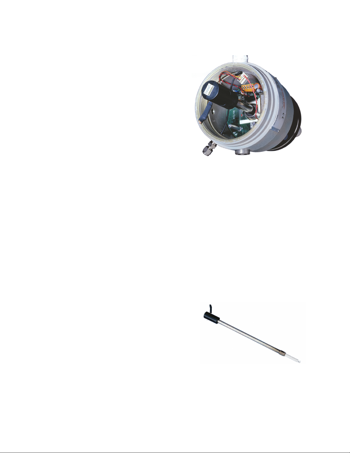
Sensor and heater assembly
Inside the FGA 311 transmitter
Page 3

GE
Sensing
FGA 311
Specifications
Calibration gas inlet
Explosion proof version of FGA 311 in situ oxygen flue gas transmitter.
Performance
Accuracy
±3% of reading or 0.1% O
2
Measurement Resolution
Output 4 to 20 mA: 0.01 mA
RS232 Terminal Interface
0.01% O
2
Response Time
Less than 5 seconds for 63% of step change
Measurement Range
Fully field selectable via RS232 interface or onboard
switches:
• 0% to 5% O
2
• 0% to 10% O
2
• 0% to 25% O
2
Temperature
Process
• Standard: 300°F to 1200°F (150°C to 650°C)
• High temperature: 300°F to 1920°F (150°C to 1050°C)
Electronics
–4°F to 160°F (–20°C to 70°C) ambient
Flame arrestor
1 1/2 in NPT
External
ground screw
1.45 in
(368.3 mm)
19 in
(482.6 mm)
7.75 in
(196 mm)
3/4 in NPT
6.07 in (154.2 mm)
Breather
Flame arrestor
END VIEW
Calibration
Methods
• Semiautomatic by push-button
• RS232 interface
• Digipot adjustment
Recommended Gas Mixtures
5.0% O2, balance N2(dependent on application and
range)
Calibration Gas Flow
2000 cc/min (4 SCFH)
Reference Air
20 to 50 cc/min, clean, dry instrument quality air
(20.93% O2), regulated to 3 psi (0.2 bar)
Page 4

GE
Sensing
FGA 311
Specifications
Functional
Output
• Analog output: 4 to 20 mA DC, 600 S maximum,
isolated
• Digital output: RS232 communications
Power Consumption
• 115 VAC, 75 W
• 230 VAC, 135 W
Process Connection
• Standard: 1 1/2 in NPTM
• Optional: 2 in (50 mm) and larger flanges
Physical
Materials
• Probe: Process wetted or welded parts
• Standard temperature: 316 stainless steel
• High-temperature: Inconel®alloy
Enclosure
Epoxy-coated aluminum
Dimensions
15 lb (6.8 kg); 19 in (482.6 mm) probe length
Mounting
Vertical or horizontal, 1 1/2 in NPT, flanges available in
most sizes
©2005 GE. All rights reserved.
920-027C
All specifications are subject to change for product improvement without notice.
GE®is a registered trademark of General Electric Co. Other company or product
names mentioned in this document may be trademarks or registered trademarks
of their respective companies, which are not affiliated with GE.
www.gesensing.com
g
Hazardous Location Certifications
Explosion-proof/flameproof:
Class I, Division 1, Groups B,C&D
T6 (electronic housing)
T4 (sensor probe)
ISSeP02ATEX028 X, Electronics:
II 2 GD EEx d IIB T6
ISSeP02ATEX028 X, Process:
II 2 GD EEx d IIB T2
Environmental
Weatherproof Type 4x/IP66
European Compliance
Complies with EMC Directive 89/336/EEC, 73/23/EEC LVD
(Installation Category II, Pollution Degree 2)
Order Information
Record selected option in blank indicated at bottom of form.
FGA 311 In Situ Flue Gas Analyzer
Package
1 Weatherproof
2 Explosion-proof; 19 in (0.5 m) only
Power
1 115 V
2 230 V
Probe Length
1 19 in (0.5 m)
2 39 in (1 m)
3 60 in (1.5 m)
4 79 in (2 m)
Temperature
1 Standard temperature, 1202°F (650°C)
maximum
2 High temperature, 1922°F (1050°C)
maximum
Special
0 None
1 Special (consult GE)
FGA 311
-
__ __ __-__ __ Use this number to order product
 Loading...