

Gentec-EO QE, XLE4 User Manual

2
WARRANTY
First Year Warranty
The Gentec-EO thermal power and energy detectors carry a one-year warranty (from date of shipment)
against material and /or workmanship defects when used under normal operating conditions. The
warranty does not cover recalibration or damages related to misuse.
Gentec-EO will repair or replace at its option any wattmeter or joulemeter which proves to be defective
during the warranty period, except in the case of product misuse.
Any unauthorized alteration or repair of the product is also not covered by the warranty.
The manufacturer is not liable for consequential damages of any kind.
In the case of a malfunction, contact the local Gentec-EO distributor or nearest Gentec-EO office to
obtain a return authorization number. Return the material to the address below.
All customers:
Gentec-EO, Inc.
445 St-Jean-Baptiste, Suite 160
Quebec, QC, G2E 5N7
Canada
Tel: (418) 651-8003
Fax: (418) 651-1174
Email: service@gentec-eo.com
Web: www.gentec-eo.com
Lifetime Warranty
Gentec-EO will warranty any thermal power and energy detector head for its lifetime as long as it has
been returned for recalibration annually from the date of shipment. This warranty includes parts and labor
for all routine repairs including normal wear under normal operating conditions.
Gentec-EO will inspect and repair the detector during the annual recalibration. Exceptions to repair at
other times will be at Gentec-EO’s option.
Not included is the cost of annual recalibration or consequential damages from using the detector.
The only condition is that the detector head must not have been subject to unauthorized service or
damaged by misuse. Misuse would include, but is not limited to; laser exposure outside Gentec-EO’s
published specifications, physical damage due to improper handling, and exposure to hostile
environments. Hostile environments would include, but are not limited to excessive temperature,
vibration, humidity (>80%), or surface contaminants; exposure to flame, solvents or water; and connection
to improper electrical voltage.
QE Series Joulemeter Instruction Manual Version 3.0 April 2014

3
TABLE OF CONTENTS
WARRANTY .......................................................................................................2
TABLE OF CONTENTS ......................................................................................3
LIST OF ILLUSTRATIONS .................................................................................4
1 GENERAL INFORMATION 5
1.1 . INTRODUCTION 5
1.2 . QE SERIES “SMART INTERFACE” CONNECTOR 6
1.3 . QE4, QE12, QE25, QE50, QE65 AND QE-B SERIES
SPECIFICATIONS 8
1.3.1 .. Specifications for the QE12, QE 25, QE50, QE65 and QE
95 MB 9
1.3.2 .. Specifications for QE4, QE12, QE 25 and QE 50 MT 15
1.3.3 .. Specifications for the QE8-B MT and BL 20
1.3.4 .. Specifications for QE4-BL 22
1.3.5 .. Specifications for XLE4 23
2 OPERATING INSTRUCTIONS 24
2.1 . When used with compatible monitor 24
2.1.1 .. General Instructions 24
2.1.2 .. Working at other wavelengths than 1.064µm (except with
QED attenuator / diffuser) 25
2.1.3 .. Working with QED attenuator / diffuser. 26
2.2 . When using an oscilloscope: 26
2.2.1 .. General Instructions 26
2.2.2 .. Working at other wavelengths than 1.064µm 27
3 DAMAGE TO THE OPTICAL ABSORBER MATERIALS 30
4 OPTIONAL ACCESSORIES 32
4.1 . QED ATTENUATOR / DIFFUSER 32
4.2 . Other Accessories: 33
5 APPENDIX A 34
5.1 . QED/12/25/50/65/95 34
6 APPENDIX B 36
6.1 . Recycling and separation procedure for WEEE directive 2002/96/EC. 36
6.2 . Separation: 36
7 DECLARATION OF CONFORMITY 37
QE Series Joulemeter Instruction Manual Version 3.0 April 2014

4
LIST OF ILLUSTRATIONS
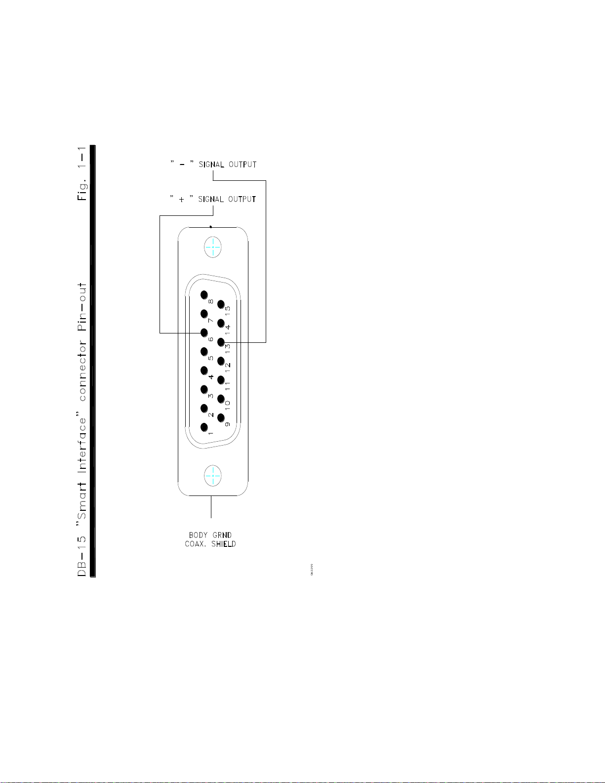
Fig. 1-1 DB-15 “Smart Interface” connector Pin-out .............................................................. 7
Fig. 2-1 Joulemeter setup ........................................................................................................ 28
Fig. 4-1 QED ATTENUATOR SPECIFICATIONS..................................................................... 31
QE Series Joulemeter Instruction Manual Version 3.0 April 2014

5
1 GENERAL INFORMATION
1
2
3
1.1 INTRODUCTION
The Gentec-EO QE Series is a robust line of high performance and high accuracy pyroelectric
joulemeters. Each modular unit is built for durability, compactness and ease of operation.
The QE optical absorber exhibits high damage thresholds and can operate at high rep-rates. The
QE series can be used to even higher energy levels with QED attenuator / diffuser.
The QE Series benefits from the use of a DB-15 male, “Smart Interface” connector, containing an
EEPROM (Erasable Electrical Programmable Read-Only Memory) programmed with the
calibration sensitivity, the spectral correction factors at different wavelengths and other data
relating to the specific QE Series joulemeter head. This connector permits the monitor to
automatically adjust to the characteristics of the joulemeter being connected.
The C0 version of the QE series (with BNC connector) does not have the “Smart Interface”
function. These joulemeters cannot be used with monitor. They must be used with an
oscilloscope or an OEM acquisition system.
All QE Serie are also available with the the INTEGRA USB Connector. This option only needs a
Computer or tablet PC using the PC-GENTEC-EO. It also a Smart Interface programmed with
the calibration sensitivity, the spectral correction factors at different wavelengths and other data
relating to the specific QE Series joulemeter head.
Every QE Series joulemeter features high intrinsic responsivity and high insensitivity to
electromagnetic interference.
The QE Series also offers an exceptionally wide dynamic range and permits energy
measurement from UV to far IR.
QE Series joulemeters are designed for user-friendly energy measurement of pulsed lasers with
monitor.
QE Series joulemeters require no power source. They can also be used with 1 M1 input
impedance oscilloscopes2 (or fast chart recorders). The calibrated V/J sensitivity is documented
in the calibration certificate of each unit. The spectral correction of this sensitivity is also
documented in the “Personal wavelength correction” certificate.
Each probe3 also includes a standard optical stand and post. An appropriate damage test target
is provided, as a safety precaution, for all QE models.
The capacitance of the cable linking the joulemeter to the electronic readout and the readout input
impedance (capacitance and resistance) constitute the total impedance load seen by the detector. The
total load capacitance, excluding the integral cable should be 30 pfd.
A DB-15 to BNC adaptor is required.
For the CO version, the post and stand are optional.
QE Series Joulemeter Instruction Manual Version 3.0 April 2014

6
QE - series
4
5
The QE series are modular low-profile heads, designed for ease of installation in tight optical
setups.
These detectors have square apertures, providing better compatibility with rectangular beam
profiles, such as pulsed gas lasers.
A corner mounting thread permits diagonal mounting of the heads to accommodate longer
rectangular beams.
These heads can be used with an optional finned heatsink to extend the power range.
The QE Series can also be used with QED optional attenuator / diffuser4 for improved
compatibility with high-energy lasers.
QE -QED series
The QE-QED series are calibrated with QED installed, they can be used from 0.3 to 2.1µm, but
cannot be used without attenuator.
1.2 QE SERIES “SMART INTERFACE” CONNECTOR 5
The DB-15 male “Smart Interface” connector contains an EEPROM (Erasable Electrical Programmable
Read-Only Memory) programmed with the calibration sensitivity and other data relating to the specific
QE joulemeter in use. Faster set-ups are obtained because the monitor automatically adjust to the
characteristics of the joulemeter, when the “Smart Interface” is connected to the monitor. The cable length
is 3 feet.
The DB-15 “Smart Interface” connector pin-out is (see Fig. 1-1):
1- USED BY MONITORS
2- " " " "
3- " " " "
4- " " " "
5- " " " "
6- “+” SIGNAL OUTPUT
7- ‘’-’’ SUPPLY VOLTAGE QE8 ONLY
8- USED BY MONITORS
9- ‘’+’’ SUPPLY VOLTAGE QE8 ONLY
10- USED BY MONITORS
11- " " " "
12- " " " "
13- “-“ SIGNAL OUTPUT
14- USED BY MONITORS
15- " " " "
SHELL- COAX. SHIELD / BODY GRND
See optional accessories section.
Does not apply to the C0 version.
QE Series Joulemeter Instruction Manual Version 3.0 April 2014
7
NOTE : Consult Gentec-EO for supply voltage requirements.
1.2.2 Integra USB connector
The Integra USB Connector is an integrated monitor that allows to plug the head directly into a
computer. It has the same serial commands as the MAESTRO and a few extra one’s (see the PCGentec-EO Manual) and uses the same PC-Gentec-EO software. All specifications are the same.
The cable length is 6 feet.
QE Series Joulemeter Instruction Manual Version 3.0 April 2014

8
1.3 QE4, QE12, QE25, QE50, QE65 AND QE-B SERIES SPECIFICATIONS
The following specifications are based on a one-year calibration cycle, an operating temperature of 15 to
28ºC and a relative humidity not exceeding 80%. Storage 5 to 45 ºC and relative humidity not exceeding
80%.
QE Series Joulemeter Instruction Manual Version 3.0 April 2014
9
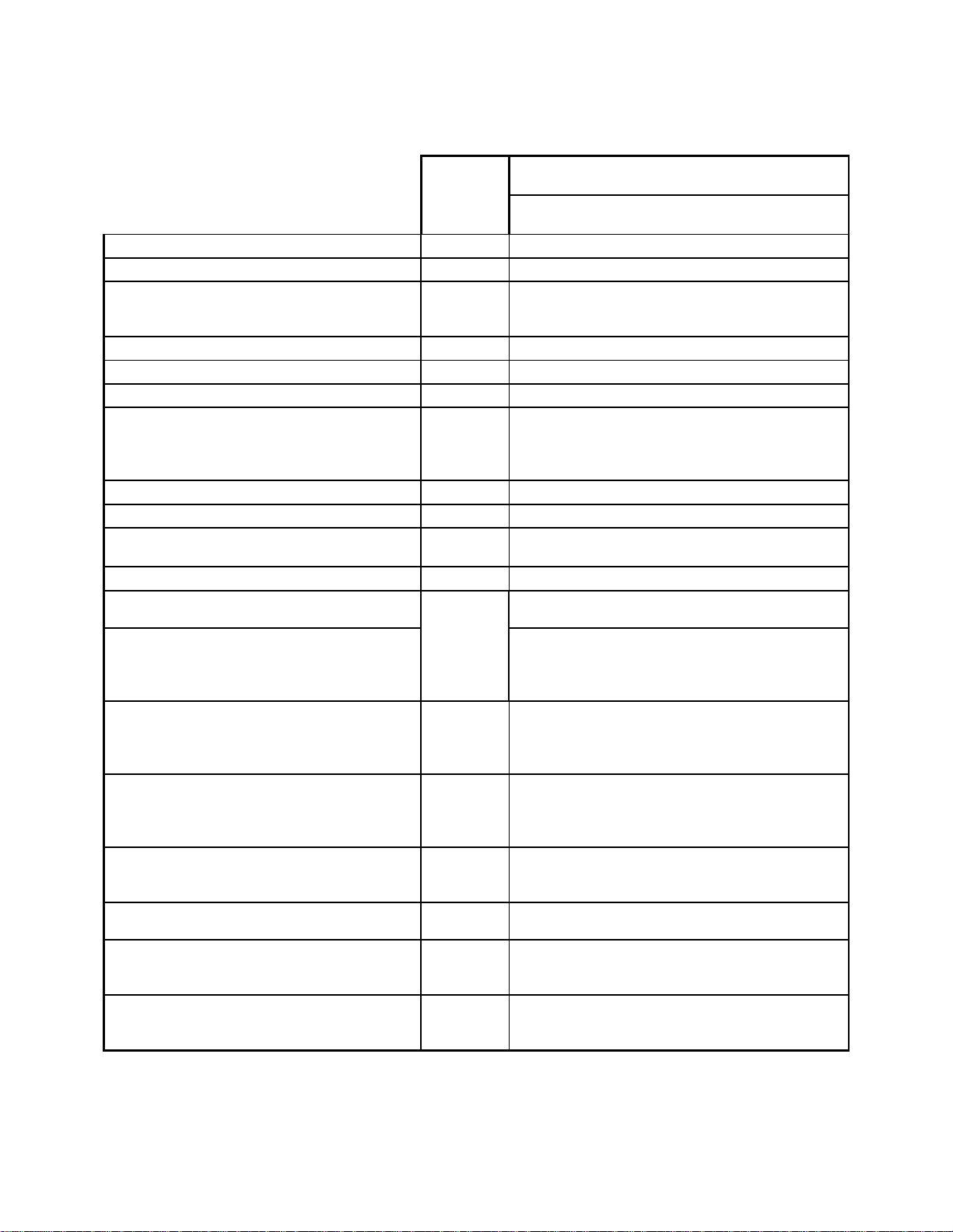
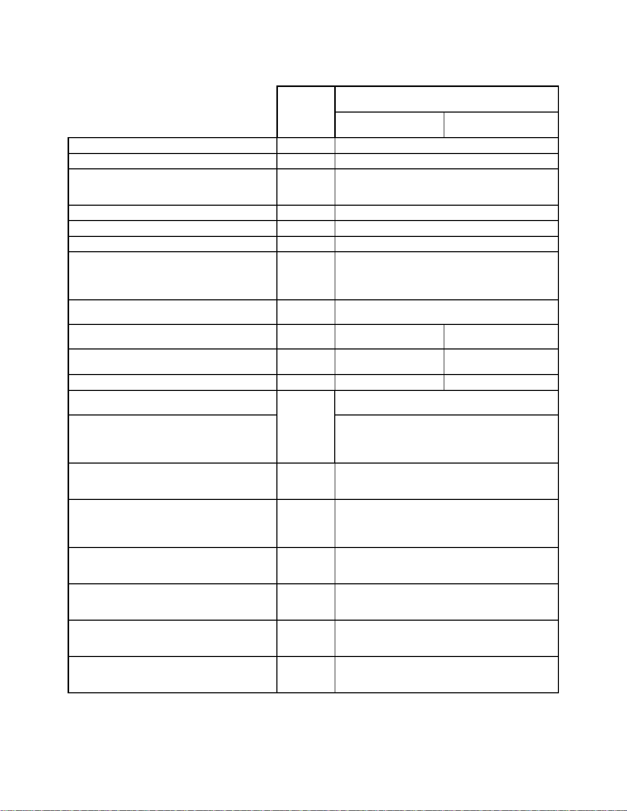
1.3.1 Specifications for the QE12, QE 25, QE50, QE65 and QE 95 MB
Footnotes
Model
QE12LP-S-MB
QE12LP-H-MB
Optical Absorber MB
Spectral Range
1, 8
0.19 – 20 µm
Calibrated Spectral Range
(Optional)
(QE-QED Series)
1, 8
0.248 – 2.5 µm
10.6 µm
0.3 – 2.1 µm
Typical Sensitivity
2, 7
60 V/J
Calibration Uncertainty
7, 2, 8, 9, 11
± 3%
Repeatability
< 0.5 %
Max. Pulse Energy 1.064 µm
0.266 µm
With QED @ 1.064 µm
QED @ 0.266 µm
3, 12
0.85 J
0.7 J
3.9 J
0.81 J
Noise Equivalent Energy (NEE) (Typ)
2, 11
0.7 µJ
Max. Repetition Rate
2, 5, 11
300 Hz
Typical Rise Time
(0-100%)
2, 11
550 µsec
Max. Pulse Width (Typ)
2, 6, 10, 11
400 µsec
Max. Energy Density
12
600 mJ/cm2 @ 1.064µm, 7ns, 10 Hz
500 mJ/cm2 @ 266nm, 7ns, 10 Hz
Max. Energy Density with QED
16 J/cm2 @1064nm, 7nsec, Single shot
8 J/cm2 @1064nm, 7nsec, 10Hz
6 J/cm2 @532nm, 7nsec, 10Hz
1 J/cm2 @266nm, 7nsec, 10Hz
Max. Average Power
Detector Alone (QE12xP-S-MB):
With optional Heatsink (QE12xP-H-MB):
12, 13
3 W (7.5 W with QED)
5 W (12.5 W with QED)
Max. Power Density
Detector Alone (QE12xP-S-MB):
With optional Heatsink (QE12xP-H-MB):
With QED :
10 W/cm² @ 3 W
10 W/cm² @ 5 W
600 W/cm²
Dimensions (H x W x D)
Detector Alone (QE12xP-S-MB):
With optional Heatsink (QE12xP-H-MB):
36 x 36 x 14 mm
36 x 36 x 33 mm
Weight : Detector Alone (QE12xP-S-MB):
With Optional Heatsink (QE12xP-H-MB):
87 g
117 g
Aperture Size QE
12:
QED 12:
12 x 12 mm
9 x 9 mm
Aperture Area Size QE
12:
QED 12:
1.4 cm
2
0.81 cm2
QE Series Joulemeter Instruction Manual Version 3.0 April 2014
10
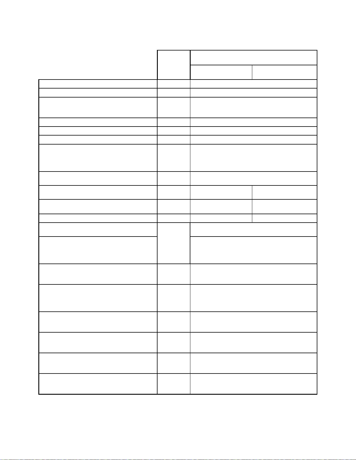
Footnotes
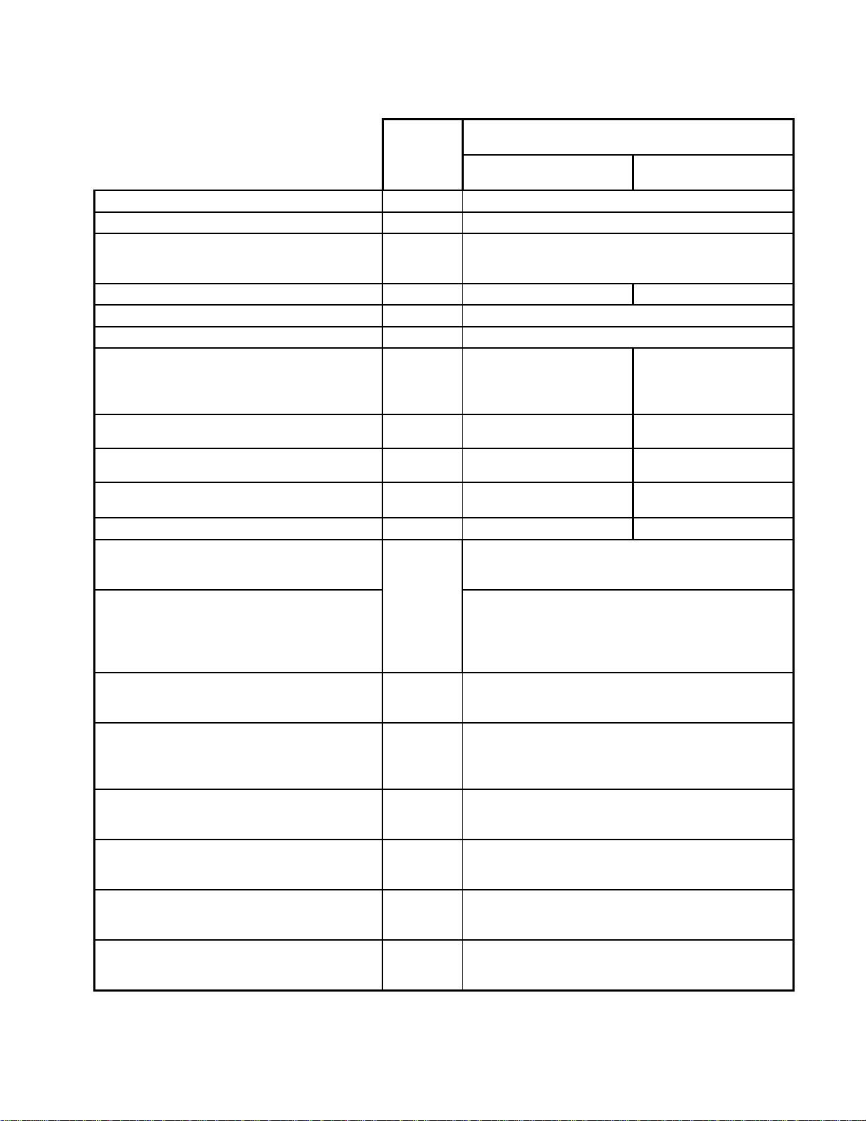
Model
QE25SP-S-MB
QE25SP-H-MB
QE25LP-S-MB
QE25LP-H-MB
Optical Absorber MB
Spectral Range
1, 8
0.19 – 20 µm
Calibrated Spectral Range
(Optional)
(QE-QED Series)
1, 8
0.248 – 2.5 µm
10.6 µm
0.3 – 2.1 µm
Typical Sensitivity
2, 7
10 V/J
Calibration Uncertainty
7, 2, 8, 9, 11
± 3%
Repeatability
< 0.5 %
Max. Pulse Energy 1.064 µm
0.266 µm
With QED @ 1.064 µm
QED @ 0.266 µm
3, 12
3.75 J
3.1 J
23 J
4.8 J
Noise Equivalent Energy (NEE)
(Typ)
2, 11
4 µJ
Max. Repetition
Rate
2, 5, 11
800 Hz
300 Hz
Typical Rise Time
(0-100%)
2, 11
200 µsec
550 µsec
Max. Pulse Width (Typ)
2, 6, 10, 11
150 µsec
400 µsec
Max. Energy Density
12
600 mJ/cm2 @ 1.064µm, 7ns, 10 Hz
500 mJ/cm2 @ 266nm, 7ns, 10 Hz
Max. Energy Density with QED
16 J/cm2 @1064nm, 7nsec, Single shot
8 J/cm2 @1064nm, 7nsec, 10Hz
6 J/cm2 @532nm, 7nsec, 10Hz
1 J/cm2 @266nm, 7nsec, 10Hz
Max. Average Power
Detector Alone (QE25xP-S-MB):
With optional Heatsink (QE25xP-H-MB):
12, 13
5 W (15 W with QED)
10 W (30 W with QED)
Max. Power Density
Detector Alone (QE25xP-S-MB):
With optional Heatsink (QE25xP-H-MB):
With QED :
10 W/cm² @ 5 W
10 W/cm² @ 10 W
600 W/cm²
Dimensions (H x W x D)
Detector Alone (QE25xP-S-MB):
With optional Heatsink (QE25xP-H-MB):
50 x 50 x 14 mm
50 x 50 x 52.5 mm
Weight
Detector Alone (QE25xP-S-MB):
With Optional Heatsink (QE25xP-H-MB):
120 g
187 g
Aperture Size
QE 25:
QED 25:
25 x 25 mm
22 x 22 mm
Aperture Area Size
QE 25:
QED 25:
6.25 cm
2
4.84 cm2
QE Series Joulemeter Instruction Manual Version 3.0 April 2014
11
Footnotes
Model
QE50SP-S-MB
QE50SP-H-MB
QE50LP-S-MB
QE50LP-H-MB
Optical Absorber MB
Spectral Range
1, 8
0.19 – 20 µm
Calibrated Spectral Range
(Optional)
(QE-QED Series)
1, 8
0.248 – 2.5 µm
10.6 µm
0.3 – 2.1 µm
Typical Sensitivity
2, 7
3 V/J
Calibration Uncertainty
7, 2, 8, 9, 11
± 3%
Repeatability
< 0.5 %
Max. Pulse Energy 1.064 µm
0.266 µm
With QED @ 1.064 µm
QED @ 0.266 µm
3, 12
15 J
12.5 J
85 J
22 J
Noise Equivalent Energy (NEE)
(Typ)
2, 11
10 µJ
Max. Repetition
Rate
2, 5, 11
500 Hz
200 Hz
Typical Rise Time
(0-100%)
2, 11
300 µsec
900 µsec
Max. Pulse Width (Typ)
2, 6, 10, 11
225 µsec
675 µsec
Max. Energy Density
12
600 mJ/cm2 @ 1.064µm, 7ns, 10 Hz
500 mJ/cm2 @ 266nm, 7ns, 10 Hz
Max. Energy Density with QED
16 J/cm2 @1064nm, 7nsec, Single shot
8 J/cm2 @1064nm, 7nsec, 10Hz
6 J/cm2 @532nm, 7nsec, 10Hz
1 J/cm2 @266nm, 7nsec, 10Hz
Max. Average Power
Detector Alone (QE50xP-S-MB):
With optional Heatsink (QE50xP-H-MB):
12, 13
10 W (25 W with QED)
20 W (45 W with QED)
Max. Power Density
Detector Alone (QE50xP-S-MB):
With optional Heatsink (QE50xP-H-MB):
With QED :
10 W/cm² @ 10 W
5 W/cm² @ 20 W
600 W/cm²
Dimensions (H x W x D)
Detector Alone (QE50xP-S-MB):
With optional Heatsink (QE50xP-H-MB):
75 x 75 x 15 mm
75 x 75 x 44 mm
Weight
Detector Alone (QE50xP-S-MB):
With Optional Heatsink (QE50xP-H-MB):
209 g
338 g
Aperture Size
QE 50:
QED 50:
50 x 50 mm
47 x 47 mm
Aperture Area Size
QE 50:
QED 50:
25 cm
2
22.09 cm2
QE Series Joulemeter Instruction Manual Version 3.0 April 2014
12
Footnotes
Model
QE65LP-S-MB
QE65LP-H-MB
QE65ELP-S-MB
QE65ELP-H-MB
Optical Absorber
MB
Spectral Range
1, 8
0.19 – 20 µm
Calibrated Spectral Range
(Optional)
(QE-QED Series)
1, 8
0.248 – 2.5 µm
10.6 µm
0.3 – 2.1 µm
Typical Sensitivity
2, 7
4 V/J
1.5 V/J
Calibration Uncertainty
7, 2, 8, 9, 11
± 3%
Repeatability
< 0.5 %
Max. Pulse Energy 1.064 µm
0.266 µm
With QED @ 1.064 µm
QED @ 0.266 µm
3, 12
25 J
20 J
125 J
35 J
50 J
(µs pulse, single shot)
200 J
(µs pulse, single shot)
Noise Equivalent Energy (NEE)
(Typ)
2, 11
10 µJ
20 µJ
Max. Repetition
Rate
2, 5, 11
100 Hz
20 Hz
Typical Rise Time
(0-100%)
2, 11
1000 µsec
6000 µsec
Max. Pulse Width (Typ)
2, 6, 10, 11
700 µsec
5000 µsec
Max. Energy Density
12
1200 mJ/cm2 @ 1064nm, 150µs, 10 Hz
600 mJ/cm2 @ 1064nm, 7ns, 10 Hz
500 mJ/cm2 @ 266nm, 7ns, 10 Hz
Max. Energy Density with QED
14 J/cm2 @1064nm, 150µs, 10Hz
16 J/cm2 @1064nm, 7ns, Single shot
8 J/cm2 @1064nm, 7ns, 10Hz
6 J/cm2 @532nm, 7ns, 10Hz
1 J/cm2 @266nm, 7ns, 10Hz
Max. Average Power
Detector Alone (QE65xP-S-MB):
With optional Heatsink (QE65xP-H-MB):
12, 13
12 W (30 W with QED)
40 W (90 W with QED)
Max. Power Density
Detector Alone (QE65xP-S-MB):
With optional Heatsink (QE65xP-H-MB):
With QED :
10 W/cm² @ 12 W
5 W/cm² @ 40 W
600 W/cm²
Dimensions (H x W x D)
Detector Alone (QE65xP-S-MB):
With optional Heatsink (QE65xP-H-MB):
90 x 90 x 20 mm
90 x 90 x 94 mm
Weight
Detector Alone (QE65xP-S-MB):
With optional Heatsink (QE65xP-H-MB):
440 g
900 g
Aperture Size
QE 65:
QED 65:
65 x 65 mm
62 x 62 mm
Aperture Area Size
QE 65:
QED 65:
42 cm
2
38 cm2
QE Series Joulemeter Instruction Manual Version 3.0 April 2014
 Loading...