

Page 1
Page 2

Revision 1.5 II
Warranty
First Year Warranty
The Gentec-EO thermal power detectors carry a one-year warranty (from date of shipment) against
material and /or workmanship defects when used under normal operating conditions. The warranty does
not cover recalibration, or damages related to misuse.
Gentec-EO will repair or replace at our option any FLASH which proves to be defective during the
warranty period; except in the case of product misuse.
Any unauthorized alteration or repair of the product is also not covered by the warranty.
The manufacturer is not liable for consequential damages of any kind.
In the case of a malfunction, contact your local Gentec-EO distributor or the nearest Gentec-EO office to
obtain a return authorization number. Return the material to the appropriate address below.
Contacting Gentec Electro-Optics Inc.
To help us answer your calls more efficiently please have the model number of the detector you are
using, ready before calling Customer Support.
All customers:
Gentec-EO, Inc.
445 St-Jean-Baptiste, Suite 160
Quebec, QC, G2E 5N7
Canada
Tel: (418) 651-8003
Fax: (418) 651-1174
Email: [email protected]
Web: www.gentec-eo.com
Lifetime Warranty
Gentec-EO will guarantee any FLASH detector for its lifetime, as long as it has been returned for
recalibration annually, from the shipment date. This warranty includes parts and labor for all routine
repairs including normal wear under normal operating conditions.
Gentec-EO will inspect and repair the detector during the annual recalibration. Repairs at other times will
be at Gentec-EO’s option.
The cost of annual recalibration, or consequential damages from using the detector, is not included.
The only condition is that the detector must not have been subject to unauthorized service or damaged by
misuse. Misuse would include, but is not limited to: laser exposure outside Gentec-EO’s published
specifications, physical damage due to improper handling, and exposure to hostile environments. Hostile
environments would include, but are not limited to: excessive temperature, vibration, humidity, or surface
contaminants; exposure to flame, solvents or water; and connection to improper electrical voltage.
FLASH Series Instruction Manual Gentec Electro-Optics Inc. All rights reserved
Page 3

Revision 1.5 III
SAFETY INFORMATION
Do not use the Flash if the device looks damaged, or if you suspect that the Flash is not operating
properly.
The user must wait for a while before handling the head of the detector after power is applied.
Surfaces of the detector’s head get very hot and there is a risk of injury if they are not allowed to cool
down.
Note: This equipment has been tested and found to comply with the limits for a Class B digital
device, pursuant to part 15 of the FCC Rules. These limits are designed to provide
reasonable protection against harmful interference in a residential installation. This
equipment generates, uses, and can radiate radio frequency energy and, if not installed
and used in accordance with the instructions, may cause harmful interference to radio
communications. However, there is no guarantee that interference will not occur with a
particular installation. If this equipment does cause harmful interference to radio or
television reception, which can be determined by turning the equipment off and on, it is
suggested to try to correct the interference by taking one or more of the following steps:
• Reorient or relocate the receiving antenna.
• Increase the distance between the equipment and receiver.
• Connect the equipment to an outlet that is on a different circuit than the receiver.
• Consult the dealer or an experienced radio/TV technician for help.
Caution: Changes or modifications not expressly approved in writing by Gentec-EO Inc. may
void the user’s authority to operate this equipment.
TABLE OF CONTENTS
FLASH Series Instruction Manual Gentec Electro-Optics Inc. All rights reserved
Page 4

Revision 1.5 IV
WARRANTY ................................................................................................................................................. II
TABLE OF CONTENTS .............................................................................................................................. III
1. FLASH SERIES HANDHELD LASER PROBE ................................................................................... 1
1.1 Introduction ................................................................................................................................................................................................. 1
1.2 Basic operating instructions (Power mode) ............................................................................................................................................... 2
1.3 Basic operating instructions (Energy mode) .............................................................................................................................................. 2
1.4 Replacing the batteries ................................................................................................................................................................................ 4
1.4 Flash series specifications ................................................................................................................................................................................ 4
1.4.1 Power mode ................................................................................................................................................................................................ 5
1.4.2 Energy mode............................................................................................................................................................................................... 5
2 OPERATING INSTRUCTIONS ............................................................................................................ 6
2.1 Activation of the device and measuring the power of a laser ................................................................................................................... 7
2.2 Semi-continuous mode (Does not work in energy mode [Joule]) ............................................................................................................. 8
2.3 Wavelength selection (CO2 / YAG / Other) ............................................................................................................................................... 9
2.4 User’s self calibration (see Appendix A for typical wavelength correction factors) ............................................................................... 9
2.5 LCD backlight............................................................................................................................................................................................ 10
2.6 Error Cases ............................................................................................................................................................................................... 10
2.7 Displays over 10000 W (Only for the FLASH-10K) ................................................................................................................................ 11
2.8 Using the FLASH in energy mode ............................................................................................................................................................ 11
2 GENERAL INFORMATION ............................................................................................................... 13
2.1 General instructions ................................ ................................................................ ................................................................ .................. 13
2.2 Safety operation notes ............................................................................................................................................................................... 14
2.3 Damage to the optical absorber material ................................................................................................................................................. 14
DECLARATION OF CONFORMITY ........................................................................................................... 16
APPENDIX A: TYPICAL WAVELENGTH CORRECTION ........................................................................ 17
APPENDIX B: OPTIONAL FLASH STAND ............................................................................................... 18
APPENDIX C: WEEE DIRECTIVE ............................................................................................................. 19
FLASH Series Instruction Manual Gentec Electro-Optics Inc. All rights reserved
Page 5

Revision 1.5 1
1. FLASH SERIES HANDHELD LASER PROBE
1.1 Introduction
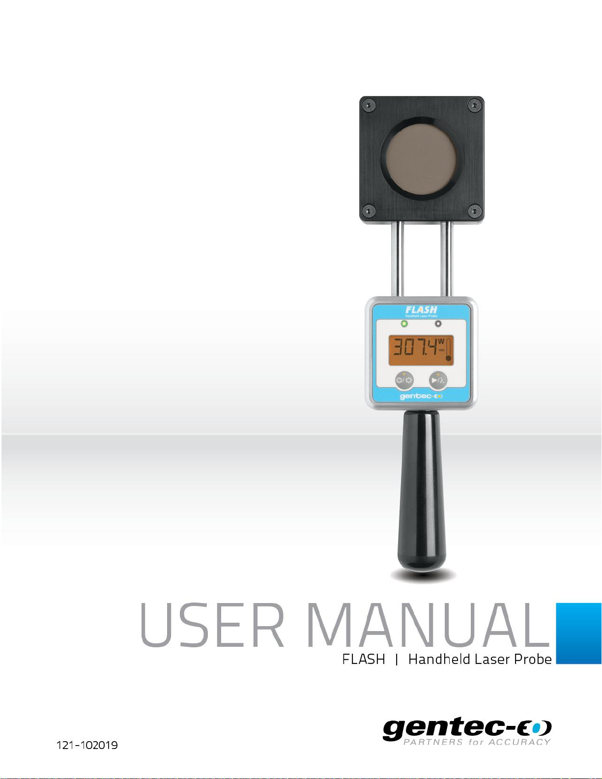
The Gentec-EO Flash Series Handheld laser probe family includes the Flash-500-55, the Flash-50010S-IPL, the Flash-500-20R5-IPL, the Flash-3K-55, the Flash-6K-55 and the Flash-10K-55.
- The Flash-500-55 detector has dimensions of 88 mm x 35 mm x 335 mm and an
aperture of 55 mm.
- The Flash-500-10S-IPL detector has dimensions of 88 mm x 35 mm x 335 mm and an
aperture of 10X10 mm.
- The Flash-500-20R5-IPL detector has dimensions of 88 mm x 35 mm x 335 mm and
an aperture of 20X5 mm.
- The Flash-3K-55 detector has dimensions of 88 mm x 45 mm x 335 mm and an
aperture of 55 mm.
- The Flash-6K-55 detector has dimensions of 88 mm x 36 mm x 335 mm and an
aperture of 55 mm.
- The Flash-10K-55 detector has dimensions of 88 mm x 46 mm x 335 mm and an
aperture of 55 mm.
- The high power surface absorber sensors are designed for use at high average power
densities.
The Flash detectors can measure between
- ±0.1 W (noise equivalent power) and 500 W of average power for Flash-500-55
±0.5 J (noise equivalent energy) and 350 J of energy for the Flash-500-10S-IPL,
Flash-500-20R5-IPL or FLASH-500-55 in energy mode
- ±5 W (noise equivalent power) and 3000 W of average power for Flash-3K-55
- ±20 W (noise equivalent power) and 6000 W of average power for Flash-6K-55
- ±30 W (noise equivalent power) and 10000 W of average power for Flash-10K-55
Flash detectors can be supplied with a stand (optional).
For cases where the Flash detector doesn’t have an ajustement or a calibration at a specific
wavelength in one of the three pre-set modes(CO2, YAG, Other), you can use your ‘’Wavelength
Correction Factor‘’ to adjust the power you read to a power corrected for a particular wavelength with
the detector self-calibration function.
Call your nearest Gentec-EO distributor to repair and/or to recalibrate the Flash. For Gentec-EO’s
nearest office contact information, see p. II, Contacting Gentec Electro-Optics Inc.
FLASH Series Instruction Manual Gentec Electro-Optics Inc. All rights reserved
Page 6
Revision 1.5 2
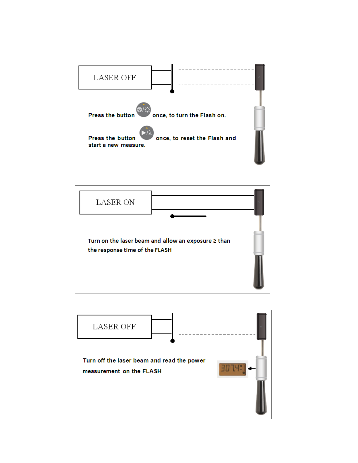
1.2 Basic operating instructions (Power mode)
A)
B)
C)
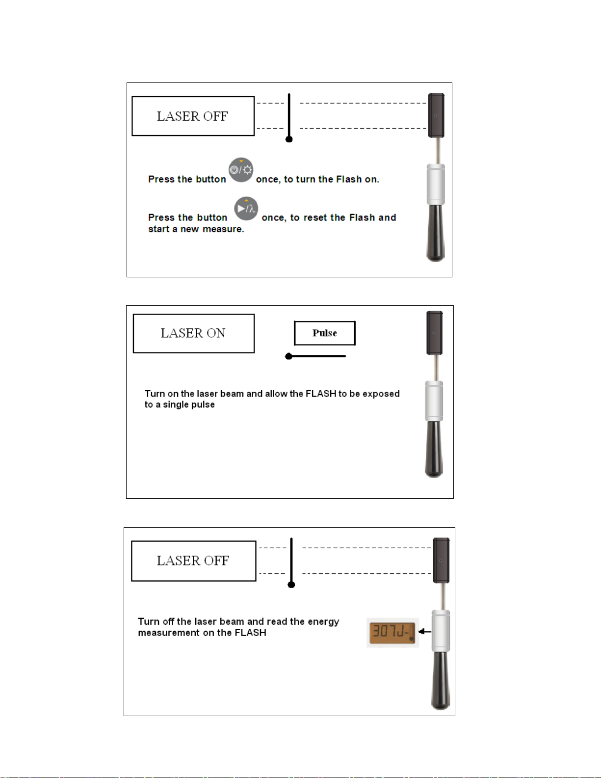
1.3 Basic operating instructions (Energy mode)
FLASH Series Instruction Manual Gentec Electro-Optics Inc. All rights reserved
Page 7
Revision 1.5 3
A)
B)
C)
FLASH Series Instruction Manual Gentec Electro-Optics Inc. All rights reserved
Page 8

Revision 1.5 4
1.4 Replacing the batteries
When the low battery indicator ( ) appears on the LCD you can still take around 300 measurements
with the Flash power meter.
To replace the 2 x AA batteries that power the Flash unscrew the 4 Phillips screws on the back of the
monitor and open up the casing.
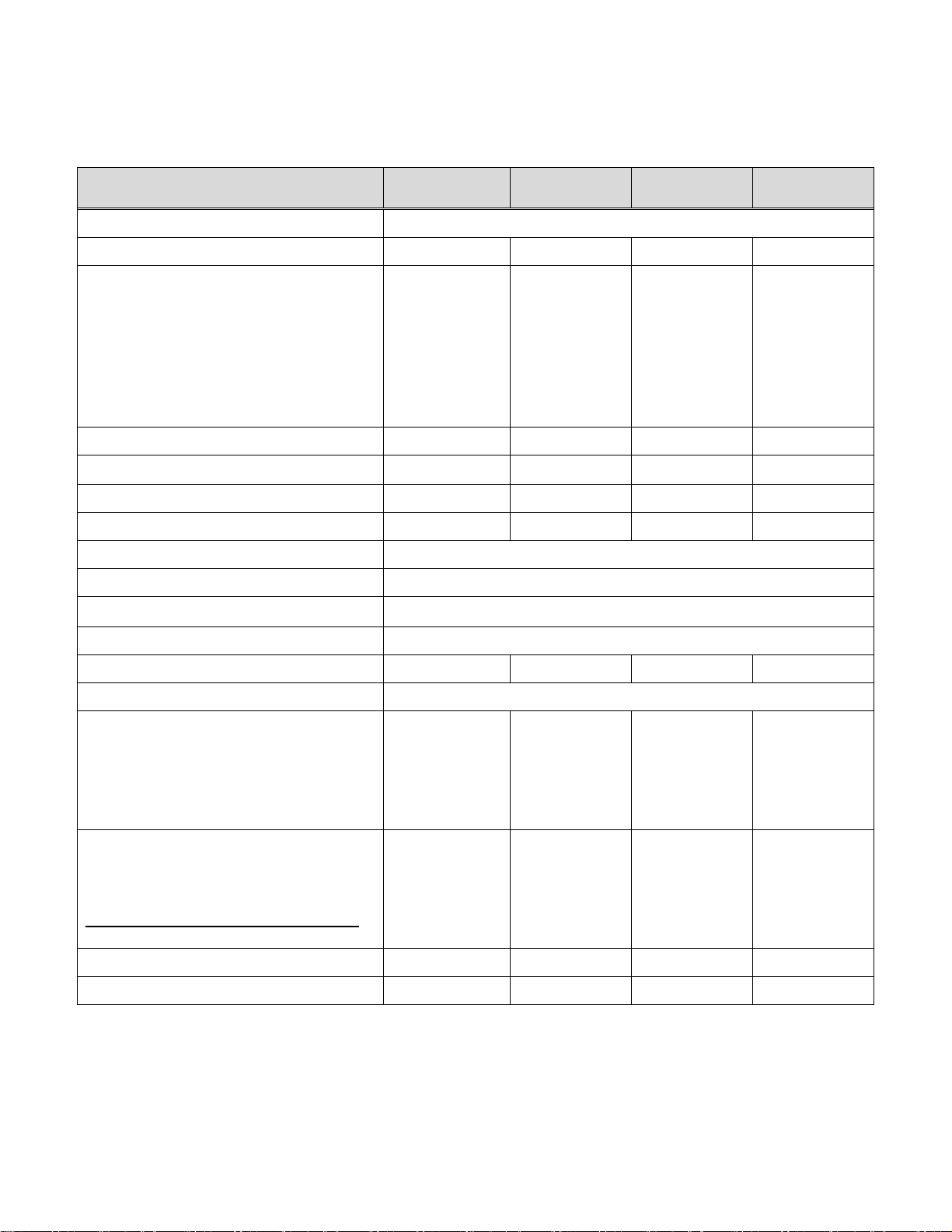
1.4 Flash series specifications
Figure 1 : Batteries compartment
FLASH Series Instruction Manual Gentec Electro-Optics Inc. All rights reserved
Page 9
Revision 1.5 5
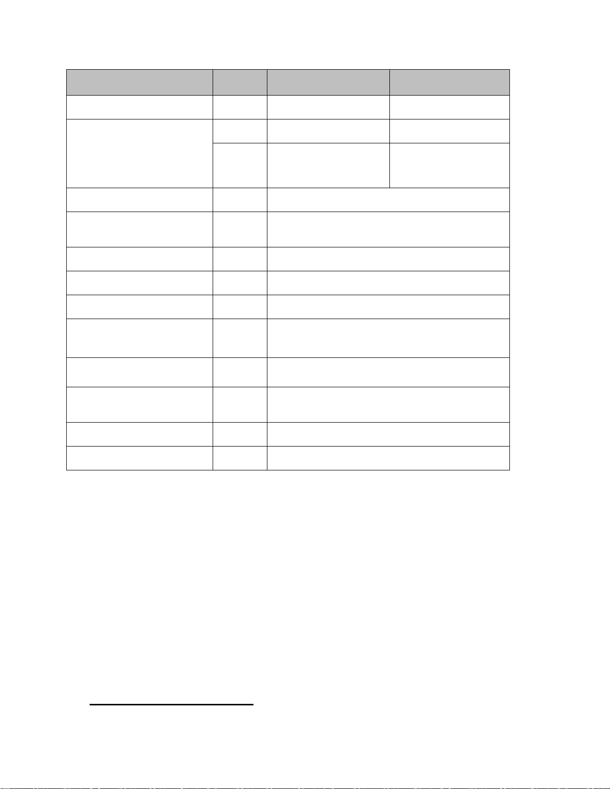
Parameter
2
FLASH-500-55
FLASH-3K-55
FLASH-6K-55
FLASH-10K-55
Spectral range
0.19-20 µm
Power Range
0.1 - 500 W
5 - 3000 W
20 – 6000 W
30 – 10 000 W
Maximum Average Power Density1064nm CW
At 100 W average power
At 500 W average power
At 3000 W average power
At 6000 W average power
At 10000 W average power
25 KW/cm2
5.0 KW/cm2
7.0 KW/cm2
5.0 KW/cm2
8.0 KW/cm2
7.0 KW/cm2
7.0 KW/cm2
5.5 KW/cm2
Display Numerical Resolution
0.1W
1W
1W
1W
1
Measurement Accuracy
3%
5%
5%
5%
Noise Equivalent Power (NEP)
0.1W
5W
20W
30W
Maximum Allowable Absorber Temp.
65°C
65°C
75°C
75°C
Battery
2 x AA
Battery Life
5000 measurements
Operating Temperature range
10 to 40 °C < 80% Relative humidity
Storage Temperature range
10 to 60 °C < 90% Relative humidity
Response time
5 s
10 s
5 s
5 s
Maximum Laser Beam Diameter
Ø 55 mm
Maximum number of readings before
probe must be cooled
[for 25°C starting temp.]
100W 25
200W 12
300W 8
500W 5
0.5KW 6
1KW 3
1.5KW 2
3KW 1
1KW 6
2KW 3
3KW 2
6KW 1
1KW 10
2KW 5
5KW 2
10KW 1
Maximum esposure time before probe
must be cooled to 25°C
[for 25°C starting temp.]
(This is the total time for all the readings)
100W 200s
200W 100s
300W 60s
500W 40s
0.5KW 72s
1KW 36s
1.5KW 24s
3KW 12s
1KW 36s
2KW 18s
3KW 12s
6KW 6s
1KW 60s
2KW 30s
5KW 12s
10KW 6s
Weight [g]
930
1240
1520
2150
Dimensions [mm]
88X35X335
88X45X335
88X36X335
88X46X335
1.4.1 Power mode
Specifications are subject to change without notice.
1
Over 10KW the numerical resolution is 0.1KW
2
The FLASH-500-10S/20R5-IPL and the FLASH-500-55-W-IPL have the same specifications that the FLASH-500-55 except for the
measurement accuracy and wavelength range. For these instruments typical power sensitivity is used.
1.4.2 Energy mode
See power mode specifications for operating and storage temperature ranges.
FLASH Series Instruction Manual Gentec Electro-Optics Inc. All rights reserved
Page 10
Revision 1.5 6
Parameter
FLASH-500-10S/20R5-IPL
1
FLASH-500-55-W-IPL
Spectral range
µm
0.19-20
0.19-2.5
-Optical aperture
cm2 1 23.76
mm
10S : 10X10mm
20R5 : 20X5mm
Ø 55mm
Typical sensitivity
mV/J
0.013
Typical Power sensitivity /
Typical Energy sensitivity
J/W
5
Response Time
s
2
Minimum repetition period s 15
Maximum pulse width
ms
433
Energy range
(For 1.064µm ; 10ms pulse)
J
2 - 350
Maximum Average Power
Density-1064nm CW @ 10W
KW/cm2
45
Pulsed Laser Damage
Thresholds (10ms)
J/cm2
175
Noise equivalent energy
mJ
500
Accuracy
%
± 5
1
The FLASH-500-55 has the same specifications that the FLASH-500-55-W-IPL except for the accuracy and
wavelength range.
For the Flash-500-55, FLASH-3K-55, FLASH-6K-55 and FLASH-10K-55 typical energy sensitivity is used.
Energy calibration is available on special request for any Flash model.
2 OPERATING INSTRUCTIONS
Laser power detection is completely automatic. There is no need for an external timer.
FLASH Series Instruction Manual Gentec Electro-Optics Inc. All rights reserved
Page 11
Revision 1.5 7
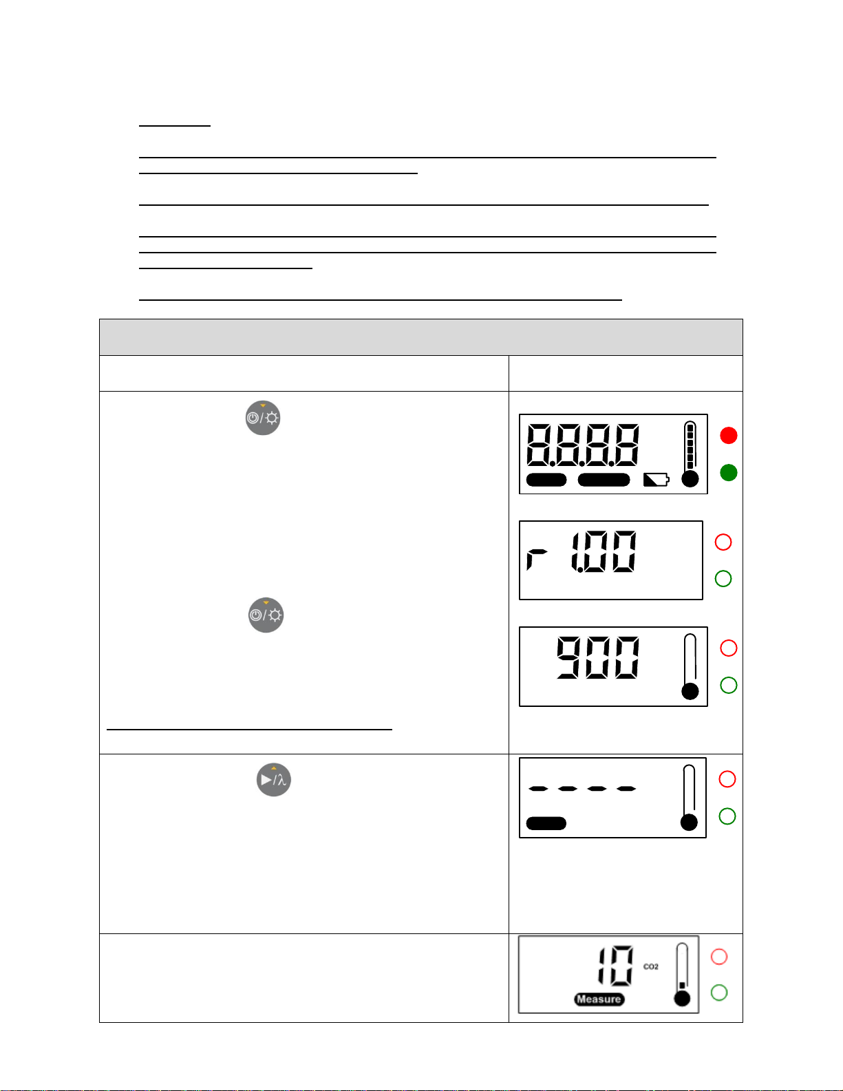
2.1 Activation of the device and measuring the power of a laser
(1) Place the FLASH on the measurement surface.
(2) Press the button once, to turn the FLASH on.
State 2.1 : The FLASH turns on and does a lamp test (all
segments of the LCD, the backlight and the 2 LEDs are ON).
State 2.2 : Displays the software revision number. The 2
LEDs and backlight are OFF.
State 2.3 : Displays the last measurement taken. The 2
LEDs and backlight are still OFF.
If you hold the button during the startup, the FLASH will
display the software revision number until the button is released.
It is recommended to leave the FLASH stabilize for 30 seconds
after startup before starting a new measure.
Do not turn the FLASH on with the laser on.
State 2.1
CO2
YAG
W
!
Measure
Ready
Other
State 2.2
State 2.3
CO2
W
(3) Press the button once, to reset the FLASH and
start a new measure.
The FLASH displays the icon « Ready » and « ---- » waiting
to detect an increase in temperature (the laser signal). The
2 LEDs are OFF.
Note : The only way to exit this mode is to make a measure or to
shut down the device (see step (6)).
CO2
W
Ready
(4) When the FLASH detects an increase in temperature
(the laser signal), it automatically starts the measure,
displays the icon « Measure » and a countdown of the
number of seconds remaining to complete the
WARNING:
WHEN ‘’HOT’’ APPEAR ON THE SCREEN TURN OFF THE LASER BEAM IMMEDIATELY
TO PREVENT DAMAGING THE DETECTOR
Be careful not to exceed the maximum levels and densities stated in the specifications.
The handle on the flash is for carrying purposes only. It is not recommended for the
user to hold the Flash during measurements. Extreme caution must be taken during
laser power measurement.
Gentec-EO is not responsible for any damage or injury caused by misuse.
FLASH Series Instruction Manual Gentec Electro-Optics Inc. All rights reserved
Page 12
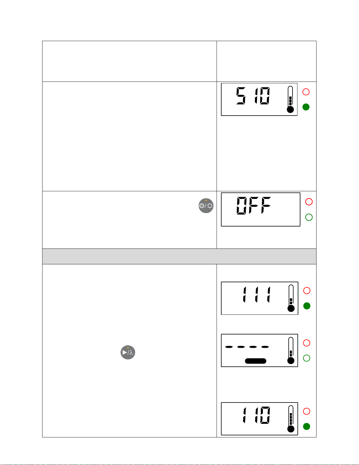
Revision 1.5 8
measurement. The 2 LEDs are OFF.
The countdown is 5 seconds for the FLASH-500, the FLASH6K, the FLASH-10K and 10 seconds for the FLASH-3K. The
thermometer is continously updated independently of the mode.
(5) As soon as the measurement is completed, the FLASH
displays the measured value and turns the backlight and
the green LED ON for 10 seconds.
Immediately after the measured value is displayed, the laser
beam can be turned off.
The red LED will be ON instead of the green LED if a
measurement error occurred. (See the error section for details).
When the green LED is off, the next measurement can be done
by returning to step (3) described above.
The value is kept on display until a new measurement is started.
(The last measurement is stored in the FLASH’s nonvolatile
memory).
CO2
W
(6) To turn the FLASH off, press and hold the button
for 3 seconds. The FLASH temporarily displays « OFF » and
turns off completely.
The FLASH turns off automatically after 5 minutes of inactivity.
2.2 Semi-continuous mode (Does not work in energy mode [Joule])
The semi-continuous mode allows no stabilization time between
two measurements.
The semi-continuous mode can be used only after a
measurement if the laser beam is still on and the max
temperature is not reached. The semi-continuous mode is
disabled when the FLASH is in error case (see section 2.6).
State 1 : Do a first measure with standard mode as
described above and let the laser ON.
State 2 : Press the button to do a fast measurement.
(No countdown)
State 3 : The second measure (semi-continuous mode) is
then displayed.
State 1
CO2
W
State 2
CO2
Measure
State 3
CO2
W
FLASH Series Instruction Manual Gentec Electro-Optics Inc. All rights reserved
Page 13
Revision 1.5 9
2.3 Wavelength selection (CO2 / YAG / Other)
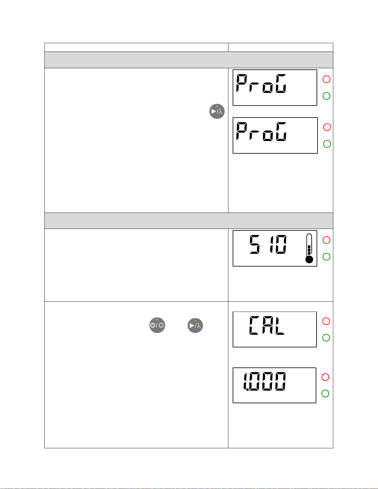
The default wavelength is YAG. If there is a calibration at
another wavelength, the default wavelength is the calibrated
one.
To change the wavelength, press and hold the button
for 3 seconds. After 3 seconds, the FLASH displays the text
« Prog » and changes the active wavelength to the next one
(Other).
The new wavelength (CO2 / YAG / Other) flashes for 3
seconds, then the device returns to the normal display (last
measure).
To select the 3rd wavelength available (CO2), you must repeat
the same procedure (long press of 3 seconds…).
The new selection is stored in the FLASH’s nonvolatile memory.
Note: The wavelength selection function is not available when
the FLASH is in “Ready” or “Measure” mode.
YAG
Other
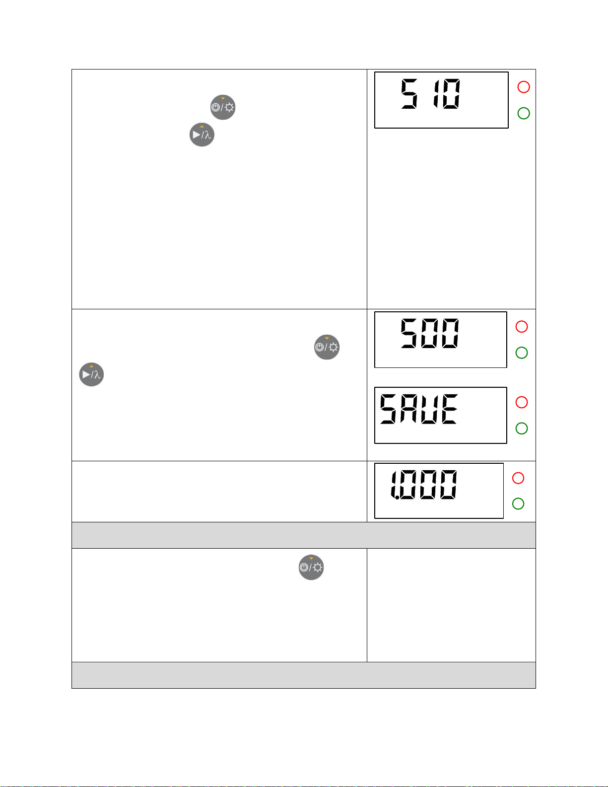
2.4 User’s self calibration (see Appendix A for typical wavelength correction factors)
Wavelength selection (section 2.3) shall be performed first to
select the appropriate wavelength mode (CO2 / YAG / Other).
(1) To adjust the sensitivity of the FLASH, first take a
measurement as described above.
Note: The self calibration is not available when the FLASH is in
“Ready” or “Measure” mode.
CO2
W
(2) When the measurement is completed, press and hold
simultaneously the 2 buttons and for 3
seconds to enter the self calibration mode.
State 2.1 : The FLASH displays the text « CAL » for 1
second.
State 2.2 : Then it displays the correction factor for 1
second.
The correction factor’s default value is 1.000 for the 3 modes
(CO2 / YAG / Other). Factory calibration also sets the correction
factor for the newly calibrated wavelength to 1.000.
State 2.1
State 2.2
CO2
FLASH Series Instruction Manual Gentec Electro-Optics Inc. All rights reserved
Page 14
Revision 1.5 10
(3) The FLASH then displays the value in watts of the last
mesurement. Press the button to decrease the
displayed value or the button to increase it, until the
desired value is reached.
Each time you press the button the correction factor increases or
decreases by 0.001 (0.1% of the full scale).
The adjustment range is from -25% to +25%. Pressing for more
than 1 second on either of the 2 keys is a typematic (a fast
increase or decrease).
After 3 seconds of inactivity, the FLASH alternates the displayed
values between the correction factor and the new value of the
last measure in watts. The self calibration can be made with
either the correction factor or the power of the last measurement
in watts.
CO2
W
(4) To save the adjusted correction factor and exit the
calibration mode, press and hold the 2 buttons and
simultaneously for 3 seconds. The text « SAVE » will
be displayed for 1 second before exiting the calibration
mode.
After 10 seconds of inactivity the device exits the self calibration
mode automatically, without saving the changes.
CO2
W
(5) To return to the factory calibrated value, the user must
enter the self calibration mode and set the correction factor
to 1.000.
CO2
2.5 LCD backlight
To light up the backlight, press the button (once).
Pressing the button again will turn off the backlight (toggle
mode).
The backlight automatiquely turns off after 30 seconds.
2.6 Error Cases
FLASH Series Instruction Manual Gentec Electro-Optics Inc. All rights reserved
Page 15
Revision 1.5 11
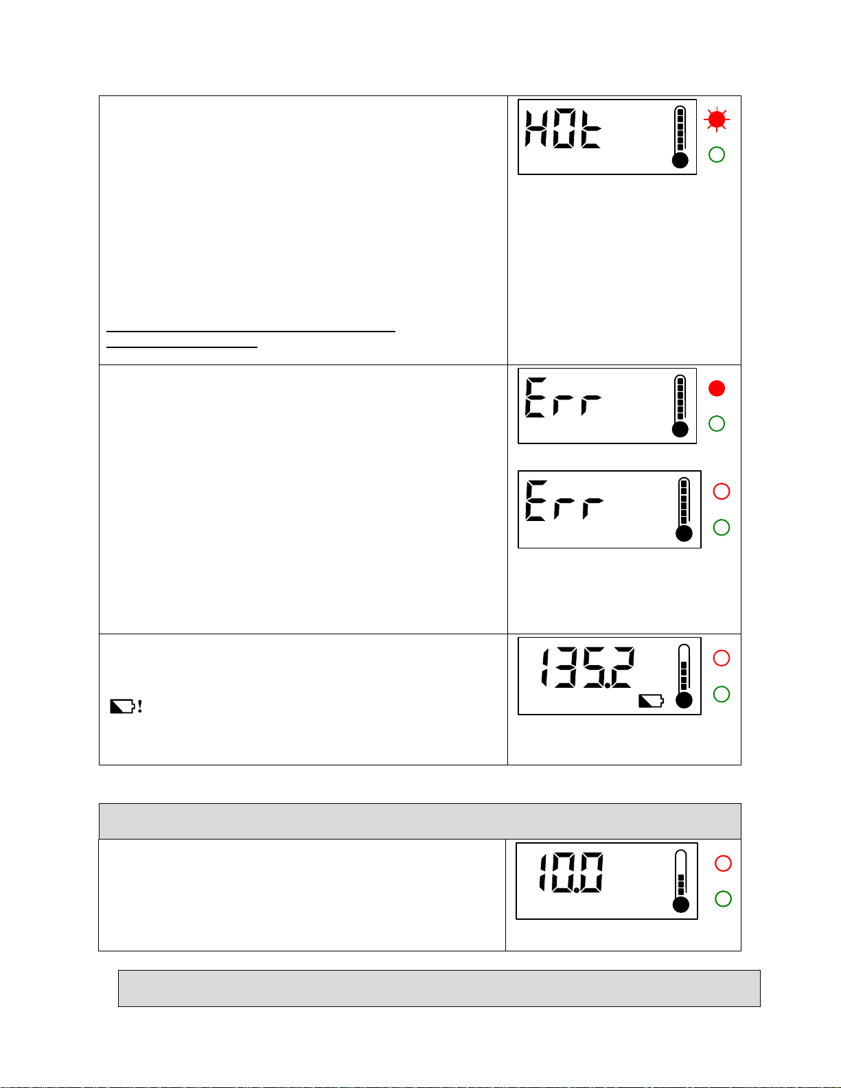
Error “Too hot” :
The FLASH continously checks the power meter head’s
temperature. If the temperature exceeds the specification
(65oC or 75°C), the graphic bar of the thermometer will be
full, the red LED will blink and the FLASH will alternately
display « HOT » and the lastest measurement. No further
measurement is permitted as long as the device is in this
error state. To exit this error, let the power meter head cool
down.
Turning off the device, does not remove the error state.
Do not immerse the detector head’s in water
(see page II : Warranty)
CO2
W
Error “Over range” :
If the FLASH is used to measure a power more that 5% over
its maximum range, or if the maximum temperature (65oC or
75oC) is reached during the measure, « Err » will appear.
Accordingly, the display will alternate between « Err » and
« Hot » if the temperature exceeds (65oC).
Also the red LED will light up instead of the green LED at
the end of the measurement.
The last valid measure is kept in nonvolatile memory until a new
valid one is taken. To exit this error, perform a new
measurement or turn off the FLASH and turn it back on.. The
head of the FLASH must also cool down if the maximum
temperature has been reached.
CO2
W
CO2
W
Error “Low Bat” :
When the battery voltage is too low, the « Low Bat » icon (
) appears.
See section 1.3 of this manuel to replace the batteries.
CO2
W
!
2.7 Displays over 10000 W (Only for the FLASH-10K)
In the special case of the FLASH-10K over 10000 W, the
display changes for the Kilowatts instead of the watts (The
maximum of the display is 12.0KW) .
Exemple : The image at the right is 10.0KW and not 10.0W.
CO2
W
2.8 Using the FLASH in energy mode
FLASH Series Instruction Manual Gentec Electro-Optics Inc. All rights reserved
Page 16
Revision 1.5 12
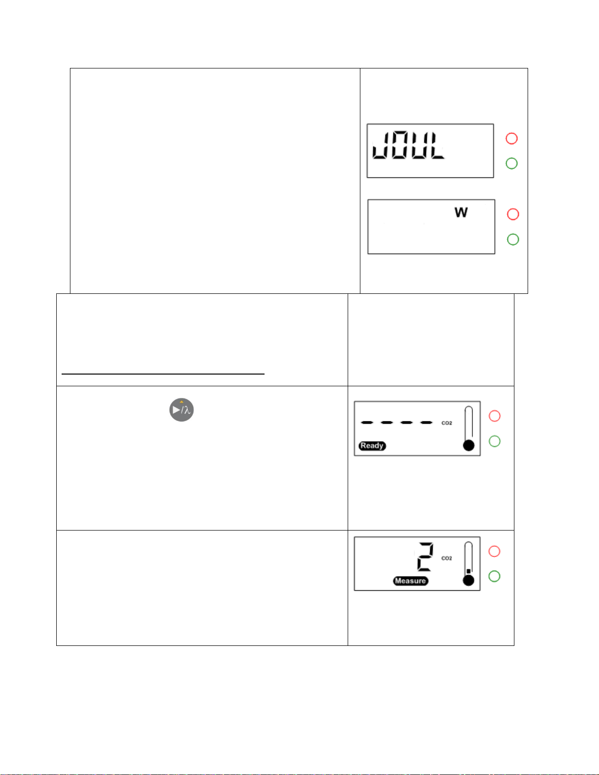
(1) To change the mode from power to energy or to
energy to power, first turn the FLASH off, Then turn the
FLASH on by pressing and holding the two buttons.
If the initial mode was power the FLASH displays
« JOUL » and changes its status for the energy mode.
If the initial mode was energy the FLASH displays « W »
and changes its status for the power mode.
The mode of the FLASH will stay the same as long as the
procedure described above is not executed.
(2) Place the FLASH on the measurement surface.
It is recommended to leave the FLASH stabilize for 30 seconds
after startup before starting a new measure.
Do not turn the FLASH on with the laser on.
(3) Press the button once to reset the FLASH and
start a new measure.
The FLASH displays the icon « Ready » and « ---- » waiting
to detect an increase in temperature (the laser signal). The
2 LEDs are OFF.
Note : The only way to exit this mode is to make a measure or to
shut down the device (see step (6)).
(4) When the FLASH detects an increase in temperature
(the laser pulse), it automatically starts the measure,
displays the icon « Measure » and a countdown of the
number of seconds remaining to complete the
measurement. The 2 LEDs are OFF.
The countdown is 2 seconds for the all the Flash-500. The
thermometer is continously updated independently of the mode.
FLASH Series Instruction Manual Gentec Electro-Optics Inc. All rights reserved
Page 17
Revision 1.5 13
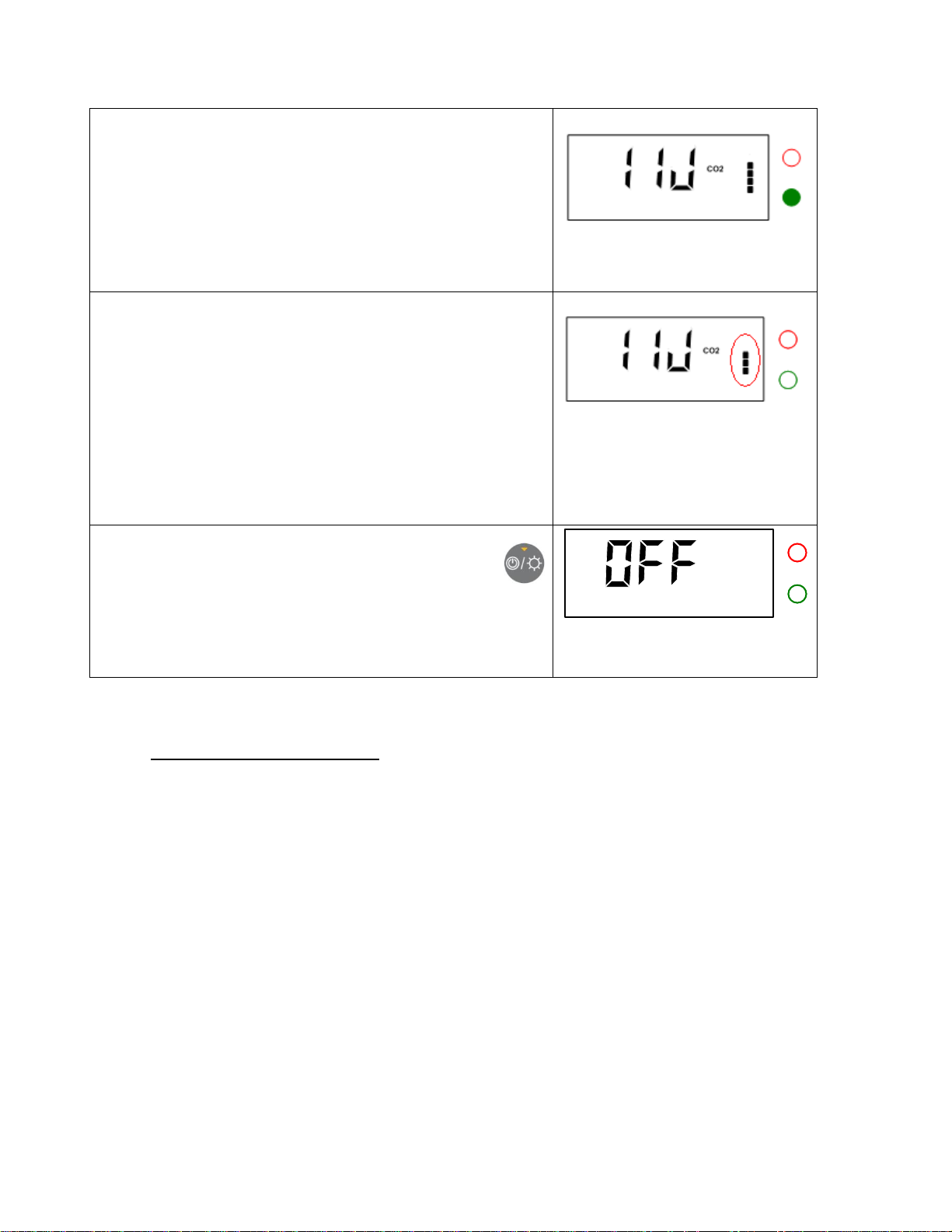
(5) As soon as the measurement is completed, the FLASH
displays the measured value and turns the backlight and
the green LED ON for 10 seconds.
The red LED will be ON instead of the green LED if a
measurement error occurred. (See the error section for details).
When the progress bar at the right of the screen is gone, the
next measurement can be done by returning to step (3)
described above.
The value is kept on display until a new measurement is started.
(The last measurement is stored in the FLASH’s nonvolatile
memory).
The progress bar indicates the time left of the 15 seconds rest
time of the detector. It is not possible to start another
measurement in until the countdown is over.
(6) To turn the FLASH off, press and hold the button
for 3 seconds. The Flash temporarily displays « OFF » and
turns off completely.
The FLASH turns off automatically after 5 minutes of inactivity.
2 GENERAL INFORMATION
2.1 General instructions
To ensure a long lifetime of accurate measurements, the FLASH powermeter should be maintained within
the following ambient conditions:
Storage environment temperature: 10 to 60°C, RH < 90%
Operating environment temperature: 10 to 40ºC, RH < 80%.
It is possible to store and operate your Gentec-EO FLASH powermeter beyond this range. For any
specific requirements, please contact your local Gentec-EO representative.
For the most accurate measurements, center the beam on the sensor face. The beam diameter on the
sensor should ideally be the same size as the beam diameter of the original calibration, which
corresponds to >98% encircled power centered on 50% of the sensor’s surface (this complies with the
International Electrotechnical Commission standard #1040: "Power and Energy Measuring Detector...").
Refer to the calibration certificate for the exact calibration beam diameter.
FLASH Series Instruction Manual Gentec Electro-Optics Inc. All rights reserved
Page 18

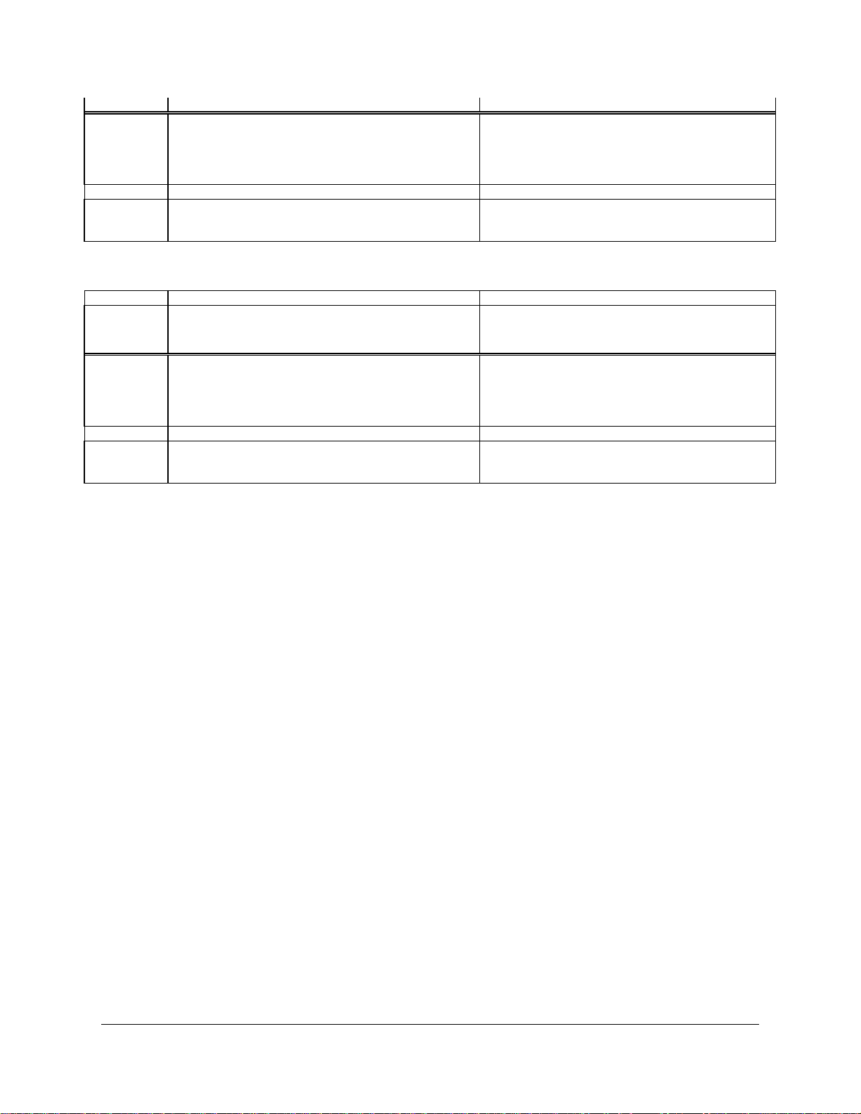
Revision 1.5 14
Laser
FLASH-500-55
FLASH-3K-55
Beam
Damage
Damage 1/e²
Min. 1/e²
Damage
Damage 1/e²
Min. 1/e²
Power
Threshold 1
Beam Diam.
2,3
Beam Diam. 2
,3,4
Threshold 1
Beam Diam.2
,3
Beam Diam.2
,3,
4
1
2
3
4
2.2 Safety operation notes
Diffusive surfaces : When using the FLASH be aware of the diffused back reflection ~ 5-15%.
Specular surfaces : When using the FLASH with the windows ‘’W’’ option be aware of the diffused back
reflection ~ 8-10%.
As on any diffusive surface, the light on the sensor coating is scattered more or less uniformly as a
Lambertian diffuser. It is recommended to use the head with a black protective sleeve to limit wide-angled
diffused reflections.
Safety laser glasses recommended.
Detector temperature while in operation: During usage, the detector head can become hot enough to
cause burns.
2.3 Damage to the optical absorber material
Damage to the optical absorber material is usually caused by exceeding the manufacturer's specified
maximum incident average power density. Refer to the specifications from section 1.4 of this manuel.
The FLASH series can measure up to 10kW. The beam diameter should always be as large as possible
to avoid damage to the absorber. We recommend between 70% and 90% of the nominal head
aperture, e.g. 4.6-5.2 cm in diameter for both Flash power meters.
In any case, the beam’s incident area should not be less than 10% of the detector’s aperture. Please
contact Gentec-EO to make measurements with such smaller beams.
The damage threshold is decreasing with the laser beam power. The following table calculates the
diameter corresponding to the damage threshold for a Gaussian beam profile. The “minimum 1/e² beam
diameter” is calculated to obtain a peak intensity 50% lower than the damage threshold and should be
considered as the “safe” minimum diameter. If there are “hot spots” in the beam profile, they must be
considered in the calculation of the peak intensity.
Yag 1,064 µm
Peak Intensity.
For Gaussian beam profile, the peak intensity is twice the beam power.
Diameter of a circle corresponding to 86% of the entire beam power.
Including a security factor of 50%
FLASH Series Instruction Manual Gentec Electro-Optics Inc. All rights reserved
Page 19
Revision 1.5 15
[kW]
[kW/cm²]
[cm]
[cm]
[kW/cm²]
[cm]
[cm]
0.1
25
0.1
0.2
0.5 5 0.5
0.8
7.0
0.6
0.9
1
6.5
0.7
1.0
2
5.7
1.0
1.4
3
5.0
1.3
1.9
FLASH-6K-55
FLASH-10K-55
3
8.0
1.3
1.9
6
7.0
1.9
2.6
7.0
1.9
2.6
10
5.5
2.6
3.3
Laser
FLASH-500-55
FLASH-3K-55
Beam
Damage
Damage 1/e²
Min. 1/e²
Damage
Damage 1/e²
Min. 1/e²
Power
Threshold 1
Beam Diam.
2,3
Beam Diam. 2
,3,4
Threshold 1
Beam Diam.2
,3
Beam Diam.2
,3,
4
[kW]
[kW/cm²]
[cm]
[cm]
[kW/cm²]
[cm]
[cm]
0.1
8.3
0.2
0.4
0.5
1.7
0.9
1.5
2.3
1.6
2.4
1
2.2
1.9
2.6
2
1.9
2.7
3.7
3
1.7
3.5
5.0
FLASH-6K-55
FLASH-10K-55
3
2.6
1.8
2.5 6
2.3
2.5
3.5
2.3
2.5
3.5
10
1.8
3.5
5.0
CO2 10.6 µm
Damage may also be caused if you use a detector with a contaminated absorber surface.
Slight discoloration of the coating may occur, but this does not affect the calibration.
In the event of major damage to the coating, the FLASH Series sensors can be recoated. Contact
your local Gentec-EO representative for information on repair and recalibration. See p. II
Contacting Gentec Electro-Optics Inc.
FLASH Series Instruction Manual Gentec Electro-Optics Inc. All rights reserved
Page 20
Revision 1.5 16
Standard
Description
Performance
Criteria
CISPR 11
Limits and methods of measurement of radio interference
characteristics of information technology equipment. Testing
and measurements of radiated emission.
Class B
EN 61000-4-2
Electromagnetic compatibility (EMC) – Part 4: Testing and
measurements techniques- Section 4.2: Electrostatic
discharge.
Class A
EN 61000-4-3
Electromagnetic compatibility (EMC) – Part 4: Testing and
measurements techniques- Section 3: Radiated, Radio
Frequency immunity.
Class A
ENV 50204
Radiated Electromagnetic field from digital radio telephonesimmunity test 900MHz pulsed
Class A
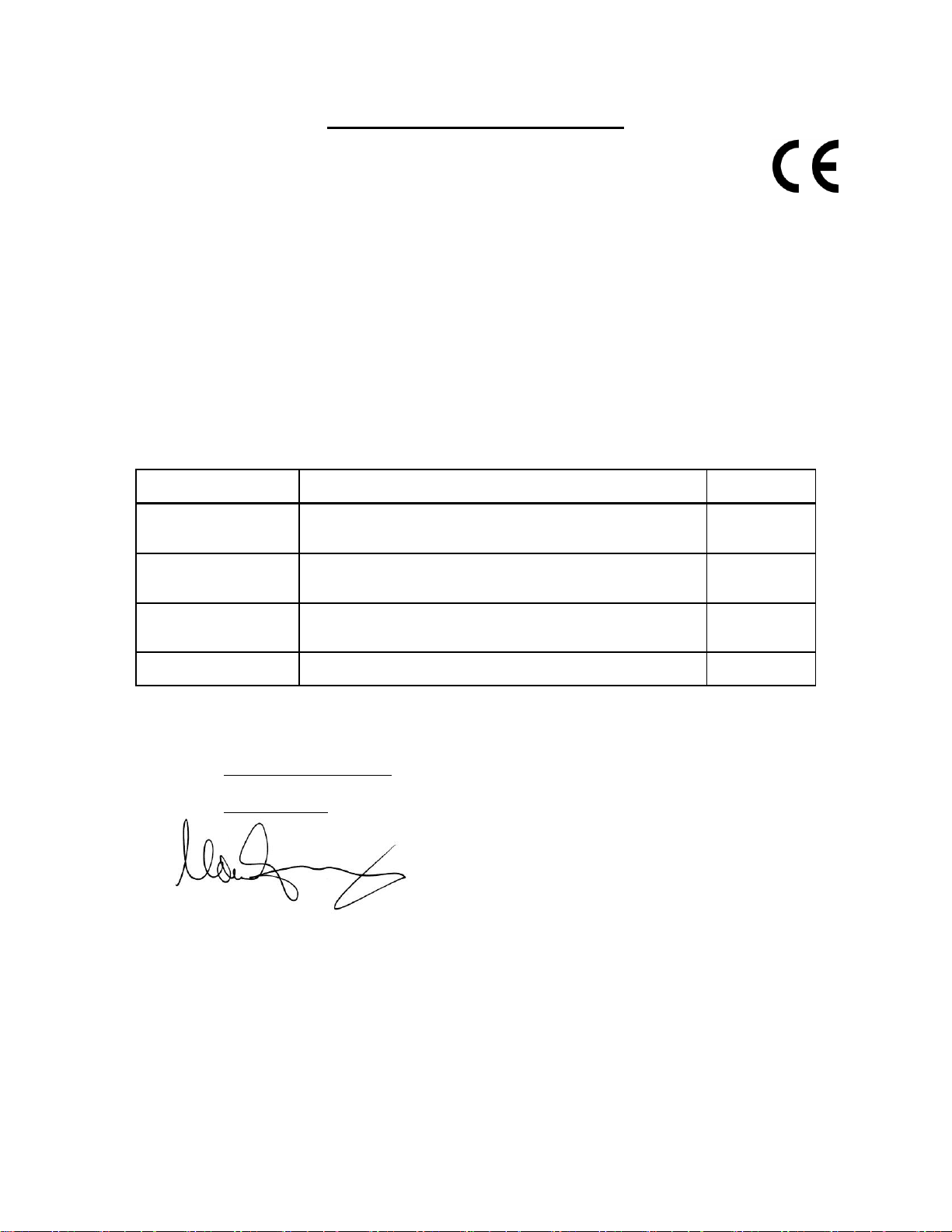
DECLARATION OF CONFORMITY
Application of Council Directive(s): 2004/108/EC EMC Directive
Manufacturer’s Name: Gentec Electro Optics, Inc.
Manufacturer’s Address: 445 St-Jean Baptiste, suite 160
Québec,QC, Canada G2E 5N7
European Representative Name: Laser Components S.A.S.
Representative’s Address: 45 bis Route des Gardes
92190 Meudon (France)
Type of Equipment: Laser Power Meter
Model No.: FLASH
Year of test & manufacture: 2010
Standard(s) to which Conformity is declared:
EN 61326-1:2006
I, the undersigned, hereby declare that the equipment specified above
conforms to the above Directive(s) and Standard(s).
Place: Québec (Québec)
Date : January 7, 2010
(President)
FLASH Series Instruction Manual Gentec Electro-Optics Inc. All rights reserved
Page 21
Revision 1.5 17
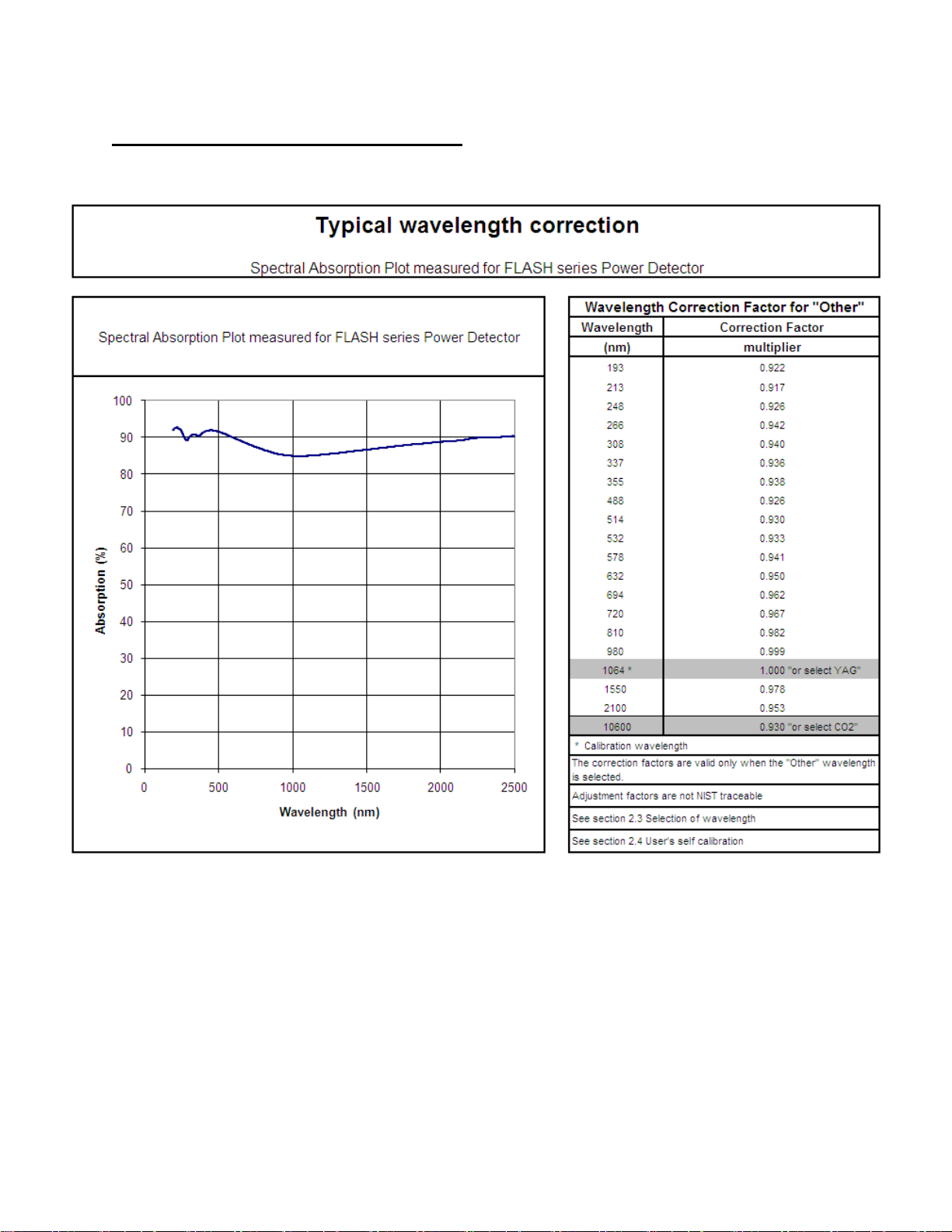
Appendix A: Typical wavelength correction
The typical wavelength correction is valid with the standard calibration only. For custom product refer to
the certificate of calibration.
FLASH Series Instruction Manual Gentec Electro-Optics Inc. All rights reserved
Page 22
Revision 1.5 18
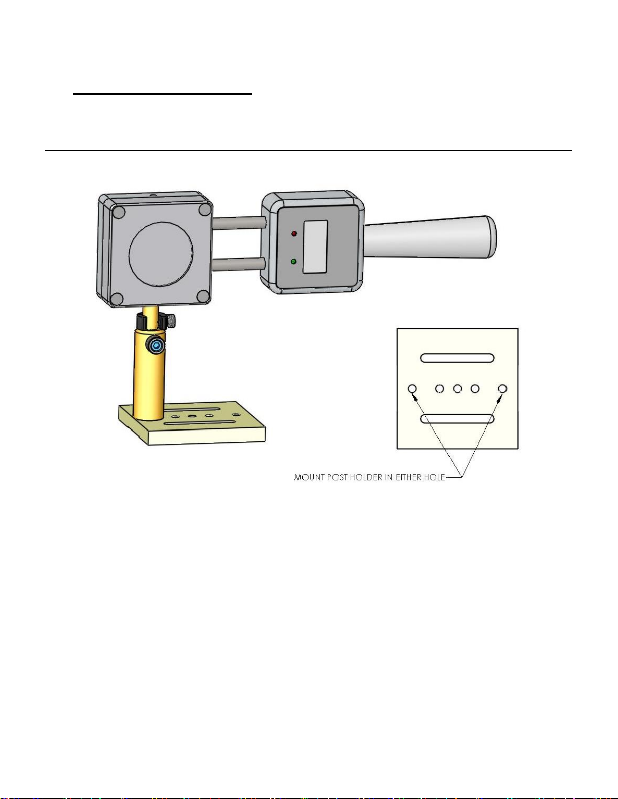
Appendix B: Optional Flash Stand
The following figure show how the stand should be assemble.
FLASH Series Instruction Manual Gentec Electro-Optics Inc. All rights reserved
Page 23

Revision 1.5 19
Appendix C: WEEE directive
- Recycling and separation procedure for WEEE directive 2002/96/EC:
This section is used by the recycling center when the detector reaches the end of its life.
Removing the insulation or troubling the inside of the monitor will void the detector warranty.
The complete Detector contains:
1 Detector
1 instruction manual
1 calibration certificate
- Separation:
Paper : Manual and certificate
Printed circuit board:
inside the Detector,
Aluminum: Detector casing.
Plastic: parts inside the Detector.
FLASH Series Instruction Manual Gentec Electro-Optics Inc. All rights reserved
Page 24
 Loading...