

Page 1
Page 2

Version 2.2 ii
Warranty
First Year Warranty
The Gentec-EO power and energy detectors carry a one-year warranty (from date of shipment) against
material and /or workmanship defects when used under normal operating conditions. The warranty does
not cover recalibration or damages related to misuse.
Gentec-EO will repair or replace at its option any wattmeter or joulemeter which proves to be defective
during the warranty period, except in the case of product misuse.
Any unauthorized alteration or repair of the product is also not covered by the warranty.
The manufacturer is not liable for consequential damages of any kind.
In the case of a malfunction, contact the local Gentec-EO distributor or nearest Gentec-EO office to obtain
a return authorization number. Return the material to the appropriate address below.
Contacting Gentec Electro-Optics Inc.
To help us answer your calls more efficiently please have the model number of the detector you are
using ready before calling Customer Support.
All customers:
Gentec-EO, Inc.
445 St-Jean-Baptiste, Suite 160
Quebec, QC, G2E 5N7
Canada
Tel: (418) 651-8003
Fax: (418) 651-1174
Email: [email protected]
Web: www.gentec-eo.com
Lifetime Warranty
Gentec-EO will warranty any power and energy detector head for its lifetime as long as it has been
returned for recalibration annually from the date of shipment. This warranty includes parts and labor for all
routine repairs including normal wear under normal operating conditions.
Gentec-EO will inspect and repair the detector during the annual recalibration. Exceptions to repair at
other times will be at Gentec-EO’s option.
Not included is the cost of annual recalibration or consequential damages from using the detector.
PH Series Instruction Manual Gentec Electro-Optics Inc. All rights reserved
Page 3

Version 2.2 iii
The only condition is that the detector head must not have been subject to unauthorized service or
damaged by misuse. Misuse would include, but is not limited to, laser exposure outside Gentec-EO’s
published specifications, physical damage due to improper handling, and exposure to hostile
environments. Hostile environments would include, but are not limited to excessive temperature,
vibration, humidity, or surface contaminants; exposure to flame, solvents or water; and connection to
improper electrical voltage.
TABLE OF CONTENTS
WARRANTY.................................................................................................................... II
First Year Warranty .................................................................................................................................................. ii
Lifetime Warranty ...................................................................................................................................................... ii
TABLE OF CONTENTS ................................................................................................. III
LIST OF ILLUSTRATIONS ............................................................................................ IV
LIST OF TABLES .......................................................................................................... IV
1 PH SERIES PHOTO DETECTORS ............................................................................ 1
1.1 INTRODUCTION ................................................................................................................................................ 1
1.2 PHOTO DETECTOR CONNECTORS ............................................................................................................... 2
1.2.1 DB-15 “intelligent” connector ........................................................................................................................ 2
1.2.2 Dimensions ..................................................................................................................................................... 3
1.3 PH SERIES SPECIFICATIONS .......................................................................................................................... 4
1.4 PH-B SERIES SPECIFICATIONS ...................................................................................................................... 6
1.5 PE-B SERIES SPECIFICATIONS ...................................................................................................................... 8
2 OPERATING INSTRUCTIONS ............................................................................................................................ 8
2.1 WITH GENTEC-EO MONITORS ..................................................................................................................... 9
2.2 QUICK POWER MEASUREMENT PROCEDURE ........................................................................................ 9
3 DAMAGE TO THE OPTICAL ABSORBER MATERIAL ........................................... 10
4 ERROR SOURCES................................................................................................... 10
4.1 OFFSET ............................................................................................................................................................... 10
4.2 OFFSET DRIFT DUE TO TEMPERATURE ................................................................................................. 10
PH Series Instruction Manual Gentec Electro-Optics Inc. All rights reserved
Page 4

Version 2.2 iv
4.3 SATURATION .................................................................................................................................................... 12
4.3.1 Procedure with a known transmission value filter .......................................................................................... 12
4.3.2 Attenuator calibration procedure ................................................................................................................... 12
4.4 MEASUREMENT OF THE AVERAGE POWER OF A PULSE LASER BEAM....................................... 12
4.5 WAVELENGTH ................................................................................................................................................. 12
4.5.1 Example ........................................................................................................................................................ 13
LIST OF ILLUSTRATIONS
FIG. 1-1 PHOTO DETECTOR DIMENSIONS. .......................................................................................................... 3
FIG 1-2 TYPICAL GE TEMPERATURE DEPENDENCE VS THE WAVELENGTH ................................ ........... 11
FIG 1-3 TYPICAL SI AND SIUV TEMPERATURE DEPENDENCE VS THE WAVELENGTH ......................... 11
FIG. 1-4 PH100-SI TYPICAL SPECTRAL RESPONSE .......................................................................................... 14
FIG. 1-5 PH100-SIUV, PH10B-SI, PE10B-SI TYPICAL SPECTRAL RESPONSE ................................................ 14
FIG. 1-6 PH20-GE, PH5B-GE, PE5B-GE TYPICAL SPECTRAL RESPONSE ..................................................... 15
FIG. 1-7 PE3B-IN TYPICAL SPECTRAL RESPONSE .......................................................................................... 15
LIST OF TABLES
TABLE I. MEASURING RANGES OF GENTEC-EO PH PHOTO DETECTORS ................................................... 1
TABLE II. MEASURING RANGES OF GENTEC-EO PH-B AND PE-B PHOTO DETECTORS ........................... 1
TABLE III. THE DB-15 CONNECTOR PIN-OUT..................................................................................................... 2
TABLE IV. PH SERIES SPECIFICATIONS FOR GENTEC-EO MONITORS ......................................................... 4
PH Series Instruction Manual Gentec Electro-Optics Inc. All rights reserved
Page 5

Version 2.3
1
Table I. Measuring ranges of Gentec-EO PH photo detectors
Configuration
PH100-Si series
PH100-SiUV series
PH20 series
Detector alone
0.3 nW to 30 mW
0.3 nW to 4 mW
2 nW to 30 mW
With OD-0.3 attenuator
With OD-1 attenuator
-
3 nW to 300 mW
0.6 nW to 8 mW
3 nW to 38 mW
-
20 nW to 300 mW
With OD-2 Attenuator
30 nW to 750 mW
30 nW to 30 mW
200 nW to 500 mW
Note: quoted maximum ranges are average power at the 1064 nm wavelength for PH100-Si and PH20-Ge, 532 nm for PH100-
SiUV, and 850 nm for PH100-SiUV with OD-2
quoted minimum ranges are average power at the 980nm for PH100-Si, 850 nm for PH-100-SiUV and 1550 nm for PH20-
Ge (Minimum ranges = 30 X NEP)
Table II. Measuring ranges of Gentec-EO PH-B and PE-B photo detectors
PH10B-Si →
1.5nW to 200µW
PE10B-Si →
1.5 pJ to 0.15µJ
PH5B-Ge →
1.2nW to 40µW
PE5B-Ge →
PE3B-Si →
PE3B-In →
500 fJ to 3.0nJ
8 fJ to 30pJ
15 fJ to 300pJ
Note PH : quoted minimum and maximum ranges are average power at the 633nm for PH10-Si and 1310nm for PH5B-Ge
(Minimum ranges = 30 X NEP). The M-Link was used for those ranges.
Note PH : quoted minimum and maximum ranges are average power at the 633nm for PE10/3B-Si and 1310nm for PE3/5B-Ge/In
(Minimum ranges = NEE). The M-Link was used for those ranges.
1 PH SERIES PHOTO DETECTORS
1.1 INTRODUCTION
The Gentec-EO Photo Detector family includes nine photo detectors sensors..
The PH100-Si, PH100Si-HA detectors use a silicon photodiode.
The PH100-SiUV, PH10B-Si, PE10B-Si, PE3B-Si detectors also use a silicon photodiode but have
enhanced sensitivity at shorter wavelengths.
The PH20-Ge, PH5B-Ge, PE5B-Ge detectors use a germanium photodiode.
The PE3B-In detectors use a InGaAs photodiode.
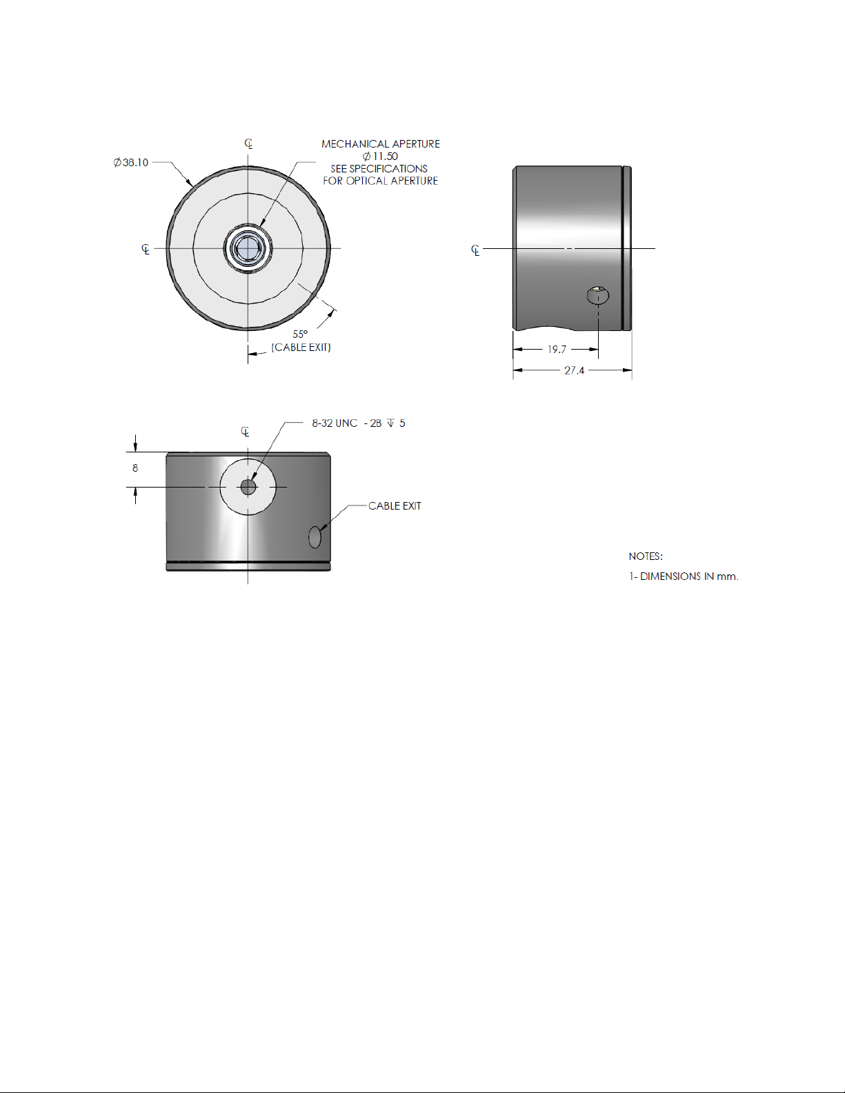
All detector heads are 27.4mm thick by 38.1 mm in diameter.
The PH and PE series are supplied with a 180 cm long flexible cable terminated with a DB-15
"intelligent" male connector, for use with Gentec-EO Monitors.
NOTE: To eliminate possible damage, do not carry the detector using the connector cable.
The PH and PE photo detectors may also be supplied with a stand.
PH Series Instruction Manual Gentec Electro-Optics Inc. All rights reserved
Page 6

Version 2.3
2
Table III. The DB-15 connector pin-out
1- USED BY MONITORS
2- " " "
3- " " "
4- " " "
5- " " "
6- + Output signal
7- ‘’-’’ SUPPLY VOLTAGE PH-B/PE-B ONLY
8- USED BY MONITORS
9- ‘’+’’ SUPPLY VOLTAGE PH-B/PE-B ONLY
10- USED BY MONITORS
11- " " "
12- " " "
13- - Output signal
14- USED BY MONITORS
15- " " "
SHELL - BODY GRND
Call your nearest Gentec-EO distributor to replace the sensor or to recalibrate the head. See p. ii,
Contacting Gentec Electro-Optics Inc.
1.2 PHOTO DETECTOR CONNECTORS
1.2.1 DB-15 “intelligent” connector and INTEGRA connector.
The DB-15 male "intelligent" and INTEGRA connectors contains an EEPROM (Erasable Electrical
Programmable Read-Only Memory) that stores information such as the model of the detector, the
calibration sensitivity of the available spectral range with or without attenuator and the applicable
scales for that specific PH and PE Series head. Wavelengths are not available where the sensor
physical properties don’t allow it.
The Gentec-eo monitors or PC-GENTEC-EO use the data in those connectors to adjust their
characteristics automatically to the power sensor being connected. No calibration procedure is
required when installing the power heads, allowing for faster set-up.
NOTE : Consult Gentec-Eo for supply voltage requierements
PH Series Instruction Manual Gentec Electro-Optics Inc. All rights reserved
Page 7
Version 2.3
3
1.2.2 Dimensions
FIG. 1-1 PHOTO DETECTOR DIMENSIONS.
PH Series Instruction Manual Gentec Electro-Optics Inc. All rights reserved
Page 8
Version 2.3
4
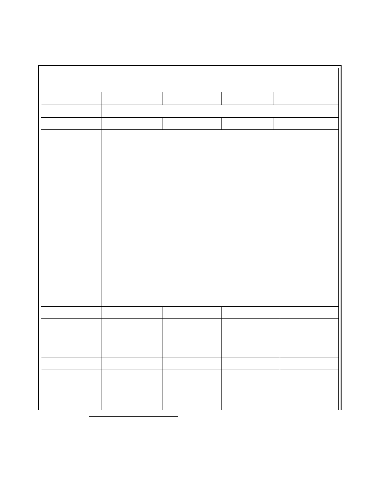
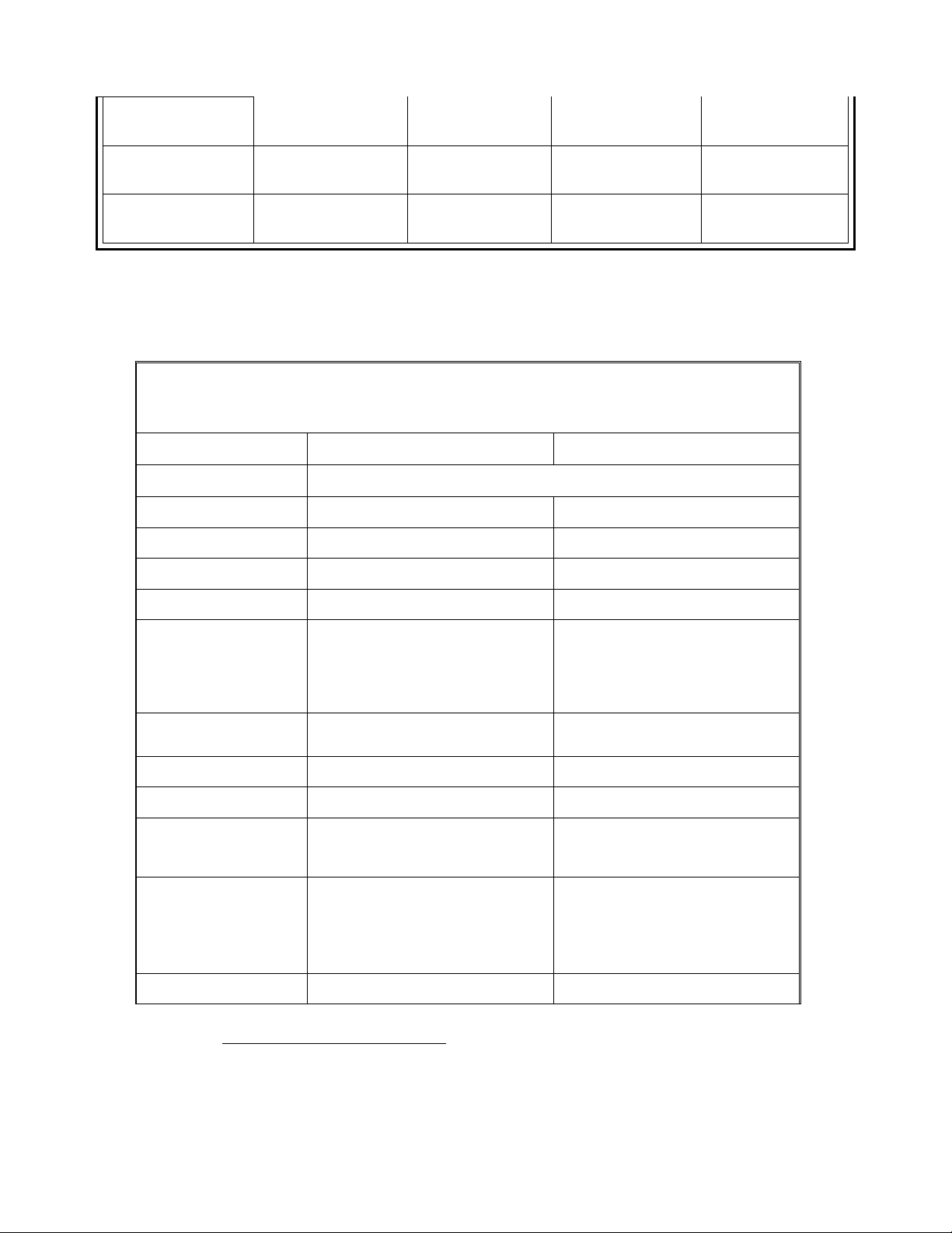
Table IV. PH Series Specifications for Gentec-eo Monitors
Detector
PH100-Si-HA
PH100-Si
PH100-SiUV
PH20-Ge
Monitor Compatibility
Maestro, M-Link, P-Link, Uno, Tuner, Solo 2, Solo PE
Absorber
Silicon
Silicon
Silicon UV
Germanium
Bandwidth
(20 mA to 1 mA) 31 kHz
(1 mA to 20 A) 31 kHz
(20 A to 2 A) 31 kHz
(2 A to 0.1 A) 29 Hz
(0.1 A to 1 nA) 16 Hz
(Bandwidth Sampling Rate 50kHz, 2048 average values.)
Integra :
(25 mA to 1 uA) 32 kHz
( 1 uA to 1 nA) 340 Hz
Secondary stage: 3 Hz
Minimum repetition
rate for average power
measurements of a
pulse laser
(20 mA to 1 mA) 155 kHz
(1 mA to 20 A) 155 kHz
(20 A to 2 A) 155 kHz
(2 A to 0.1 A) 145 Hz
(0.1 A to 1 nA) 80 Hz
Integra :
(25 mA to 1 uA) 155 kHz
( 1 uA to 1 nA) 1700 Hz
Spectral range
350 to 1080 nm
320 to 1100 nm
210 to 1080 nm
800 to 1650 nm
Peak sensitivity
980 nm
980 nm
980 nm
1550 nm
Maximum Power typ.
[@ Power Density]
36 mW
[36 mW/cm2]
(@ 1064 nm)
36 mW
[36 mW/cm2]
(@ 1064 nm)
4 mW
[65 mW/cm2]
(@ 532 nm)
30 mW
[< 320 mW/cm2]
(@ 1064 nm)
Minimum Powera
0.3 nW @ 980 nm
0.3 nW @ 980 nm
0.3 nW @ 850 nm
2 nW @ 1550 nm
Damage threshold
[Maximum Average
Power Density]
100 W/cm2
100 W/cm2
100 W/cm2
100 W/cm2
Typical Detector
saturation currentb
6.3 mA/cm2
6.3 mA/cm2
17.6 mA/cm2
140mA/cm2
a
1.3 PH SERIES SPECIFICATIONS
Warm-up until the reading without laser power is stable for several minutes before offset nulling (zeroing the
display). Null the offset after each new power up. Half an hour warm-up is recommended for measuring low powers.
Temperature ±0.5 degrees.display). Null the offset after each new power up. Half an hour warm-up is
recommended for measuring low powers. Temperature ±0.5 degrees. Minimum Power = 30 X NEP
PH Series Instruction Manual Gentec Electro-Optics Inc. All rights reserved
Page 9
Version 2.3
5
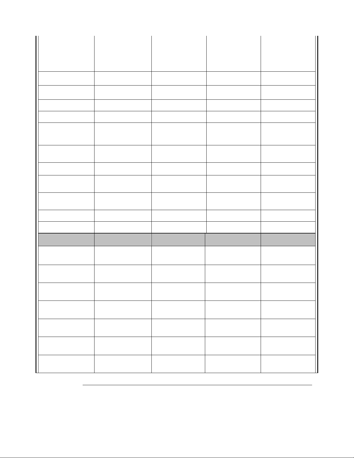
Uncertainty
350-399 nm: ±6.0%
400-449 nm : ±2.0%
450-940 nm : ±1.5%
941-980 nm : ±2.0%
981-1049 nm: ±5%
1050-1080 nm: ±7%
320-399 nm: ±6.5%
400-899 nm : ±2.5%
900-999 nm : ±3.5%
1000-1049 nm: ±5%
1050-1100 nm: ±7%
210-219 nm : ±8%
220-399 nm : ±6.5%
400-899 nm : ±2.5%
900-999 nm : ±3.5%
1000-1049 nm: ±5%
1050-1080 nm: ±7%
800-1650 nm: ±3.5%
Resolution
1.5 pW
Integra: 1 fW
1.5 pW
Integra: 1 fW
1.5 pW
Integra: 1 fW
1.5 pW
Integra: 1 fW
Temperature offset
dependence, typical
20 pA/°C
20 pA/°C
20 pA/°C
100 pA/°C
Aperture
10 mm diameter
10 mm diameter
10 mm diameter
5 mm diameter
Active Area
0.9 cm2
0.9 cm2
0.9 cm2
0.2 cm2
Response time10-90%
0.2 sec
Integra: 0.45 sec
0.2 sec
Integra: 0.45 sec
0.2 sec
Integra: 0.45 sec
0.2 sec
Integra: 0.45 sec
Beam Position
Dependence
±1% @ 780 nm
±3% @ 1064 nm
±1% @ 780 nm
±3% @ 1064 nm
±1% @652 nm
±3% @ 1064 nm
± 1 % @ 1064 nm
±3% @ 800 nm
Noisec (peak to peak)
5 pA
5 pA
5 pA
60 pA
Noise equivalent
power (NEP)
10 pW @ 980nm
10 pW @ 980nm
10 pW @ 850nm
60 pW @ 1550nm
Dimensions
27.4mm x 38.1mm
dia.
27.4mm x 38.1mm
dia.
27.4mm x 38.1mm
dia.
27.4mm x 38.1mm
dia.
Weight
130 g
130 g
130 g
130 g
Sensitivity, typical
0.5 A/W @ 980 nm
0.5 A/W @ 980 nm
0.45 A/W @ 850 nm
0.98 A/W @ 1550 nm
With attenuator
PH100-Si -
OD1/OD2
PH100-Si -
OD1/OD2
PH100-SiUV –
OD0.3/OD1/OD2
PH20-Ge-
OD1/OD2
Maximum Power typ.
w/ OD-0.3 d
-
-
11 mW @ 300 nm
-
Minimum Powera
w/ OD-0.3
-
-
0.6 nW @ 850 nm
-
Spectral range
w/ OD-0.3
-
-
210 to 1080 nm
-
Maximum Power typ.
w/ OD-1
300 mW @ 1064 nm
300 mW @ 1064 nm
38 mW @ 532 nm
300 mW @ 1064 nm
Minimum Powera
w/ OD-1
6 nW @ 980 nm
6 nW @ 980 nm
6 nW @ 850 nm
20 nW @ 1550 nm
Spectral range
w/ OD-1
420 to 1080 nm
400 to 1100 nm
400 to 1080 nm
900 to 1650 nm
Maximum Power typ.
w/ OD-2
0.75 W @ 1064 nm
0.75 W @ 1064 nm
30 mW @ 850 nm
0.50 W @ 1064 nm
b
c
d
Prior to reaching ±3% linearity error
Lowest scale . Nominal value. Depends on environmental electromagnetic interference. Typical noise on all the
Integra scales: 0.06% of Fullscale , maximum noise in the 1uA to 3 uA range: 0.4% of the Fullscale.
Damage Threshold: 0.025 J/cm2 (355 nm, 10 ns, 10 Hz)
PH Series Instruction Manual Gentec Electro-Optics Inc. All rights reserved
Page 10
Version 2.3
6
Minimum Powera
w/ OD-2
60 nW @ 980 nm
60 nW @ 980 nm
60 nW @ 850nm
200 nW @ 1550 nm
Spectral range
w/ OD-2
630 to 1080 nm
630 to 1100 nm
630 to 1080 nm
950 to 1650 nm
Uncertainty w/ OD-0.3,
1 or OD-2 attenuator
420-980 nm: ±4%
981-1049 nm: ±5%
1050-1080 nm: ±7%
400-1049 nm: ±5%
1050-1100 nm: ±7%
210-1049 nm: ±5
1050-1080 nm: ±7%
±5%
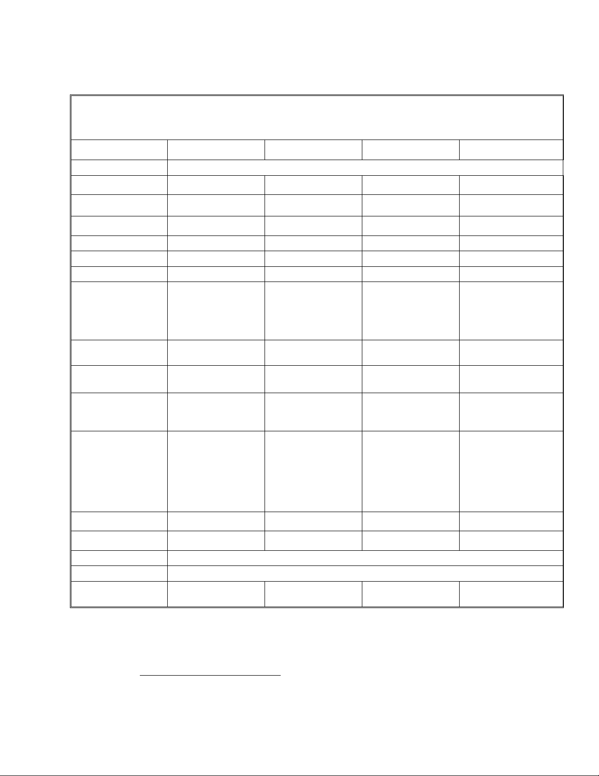
Table V. PH-B Series Specifications for Gentec-eo Monitors
Detector
PH10B-Si
PH5B-Ge
Monitor Compatibility
Maestro, M-Link, S-Link
Absorber
Silicon UV
Germanium
Spectral range
210 to 1080 nm
800 to 1650 nm
Peak sensitivity
980nm
1550nm
Sensitivity, typical
15 kV/W @ 633nm
80 kV/W @ 1047 nm
Maximum measurable
power
M-Link : 200 µW
S-Link : 175 µW
Maestro : 150 µW
(@ 633nm)
M-Link : 40 µW
S-Link : 30 µW
Maestro : 25 µW
(@ 1310 nm)
Maximum Average
Power Density
65 mW/cm2
(@ 532 nm)
<320 mW/cm2
(@ 1064 nm)
Noise equivalent power
50 pW (@ 633nm)
40 pW (@ 1310nm)
Minimum Powere
1.5 nW (@ 633nm)
1.2 nW (@ 1310nm)
Damage threshold
[Maximum Average Power
Density]
100 W/cm2
100 W/cm2
Uncertainty
210 - 219 nm: ±8.0%
220 - 399 nm: ±6.5%
400 - 899 nm: ±2.5%
900 - 999 nm: ±3.5%
1000-1049 nm: ±5.0%
1050-1080 nm: ±7.0%
800- 1650 nm : ±3.5%
Aperture
10 mm diameter
5 mm diameter
e
Specifications subject to change without notice.
1.4 PH-B SERIES SPECIFICATIONS
Warm-up until the reading without laser power is stable for several minutes before offset nulling (zeroing the
display). Null the offset after each new power up. Half an hour warm-up is recommended for measuring low powers.
Temperature ±0.5 degrees.display). Null the offset after each new power up. Half an hour warm-up is
recommended for measuring low powers. Temperature ±0.5 degrees. Minimum Power = 30 X NEP
PH Series Instruction Manual Gentec Electro-Optics Inc. All rights reserved
Page 11

Version 2.3
7
Active Area
0.9 cm2
0.2 cm2
Rise time 0-100%
≤ 0.2 sec
≤ 0.2 sec
Dimensions
38.1mm Ø x 27.4 mm
Weight
91 g
Beam Position
Dependence
±1% @ 652 nm
±3% @ 1064 nm
±1% @ 1064 nm
±3% @ 800 nm
PH Series Instruction Manual Gentec Electro-Optics Inc. All rights reserved
Page 12
Version 2.3
8
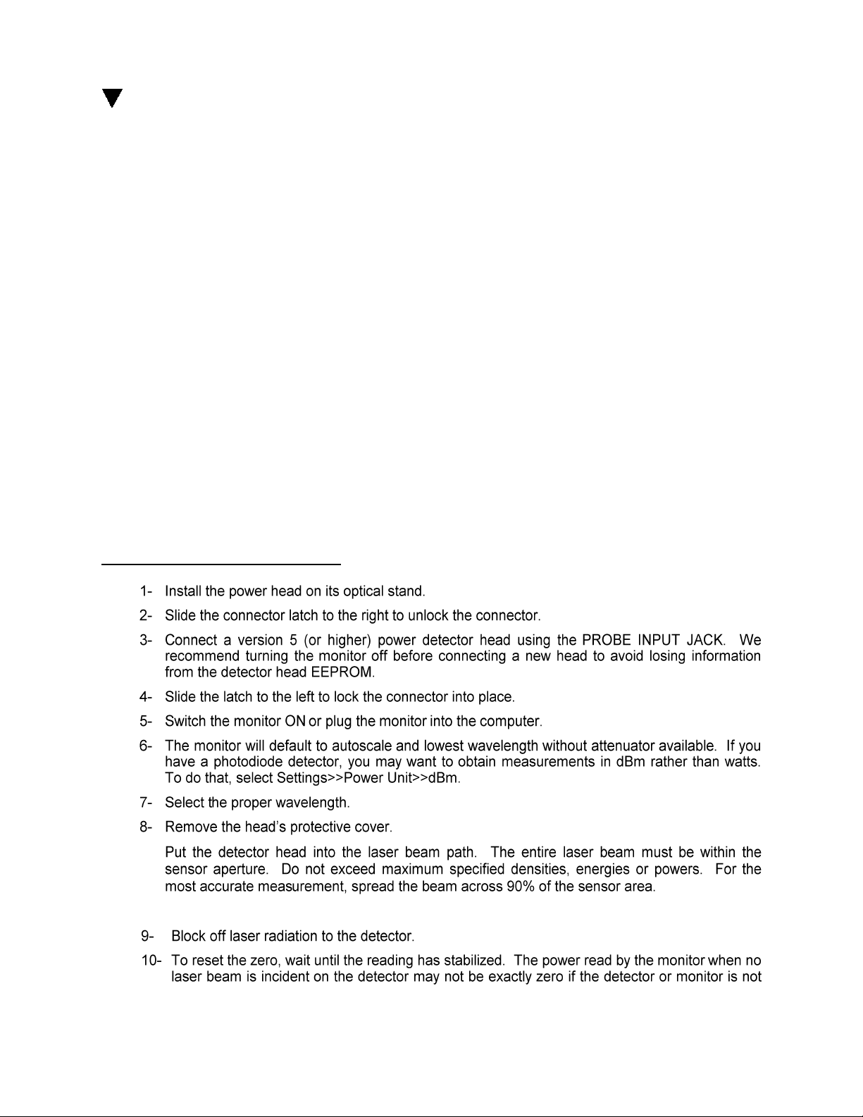
Table VI. PE-B Series Specifications for Gentec-eo Monitors
Detector
PE10B-Si
PE5B-Ge
PE3B-Si
PE3B-In
Monitor Compatibility
Maestro, M-Link, S-Link
Absorber
Silicon UV
Germanium
Silicon UV
InGaAs
Spectral range
210 to 1080 nm
800 to 1650 nm
210 to 1080 nm f
900 to 1700 nm
f
Sensitivity, typical
20 MV/J @ 634 nm
1 GV/J @ 1310 nm
100 GV/J @ 634 nm
10 GV/J @ 1310 nm
Rise Time (0-100%)
30 µs
25 µs
15 µs
12 µs
Max Repetition Rate
1000 Hz
1000 Hz
1000 Hz
1000 Hz
Max Pulse Width
10 µs
10 µs
10 µs
10 µs
Maximum
Measurable Energy
M-Link : 0.15 µJ
S-Link : 0.13 µJ
Maestro : 0.11 µJ
(@ 634nm)
M-Link : 3.0 nJ
S-Link : 2.5 nJ
Maestro : 2.0 nJ
(@ 1310 nm)
M-Link : 30 pJ
S-Link : 25 pJ
Maestro : 20 pJ
(@ 634 nm)
M-Link : 300 pJ
S-Link : 250 pJ
Maestro : 200 pJ
(@ 1310 nm)
Maximum Energy
Density
5 µJ/cm
2
5 µJ/cm2
n/a
n/a
Max Average Power
Density (@ 1064nm)
65 mW/cm2
(@ 532 nm)
<320 mW/cm2
(@ 1064 nm)
n/a
n/a
Noise Equivalent
Energy
1.5 pJ @ 634nm
1 pJ @ 1310 nm
8 fJ @ 634nm
30 fJ@ 1310nm
Uncertainty
210 - 219 nm: ±8.0%
220 - 399 nm: ±6.5%
400 - 899 nm: ±2.5%
900 - 999 nm: ±3.5%
1000 -1049 nm:
±5.0%
1050-1080 nm:
±7.0%
800-1650 nm: ±3.5%
±4% only @ 634 nm
±4% only @ 1310 nm
Effective Aperture
10 mm Ø
5 mm Ø
3 mm Ø
3 mm Ø
Active Area
0.9 cm2
0.2 cm2
0.07 cm2
0.07 cm2
Dimensions
38.1mm Ø x 27.4Dmm
Weight
91 g
Beam Position
Dependence
±1% @ 652 nm
±3% @ 1064 nm
±1% @ 1064 nm
±3% @ 800 nm
n/a
n/a
f
1.5 PE-B SERIES SPECIFICATIONS
2 OPERATING INSTRUCTIONS
The photodiode is calibrated at one wavelength and spectrally correted according to a typical
curve.
PH Series Instruction Manual Gentec Electro-Optics Inc. All rights reserved
Page 13
Version 2.3
9
2.1 WITH GENTEC-EO MONITORS
To operate the PH and PE Series photo detector, connect the detector head to the input socket on
Gentec-eo monitors with the cable supplied by Gentec-EO before turning the monitor on. (See
monitor’s instruction manual.)
Adjust the reading to zero before measurements for best accuracy. See procedure in section 2.2
below.
If you are using the fiber optic adapter, put the black protective cover on the detector head before
making the offset nulling.
If you want to subtract the room light do the offset nulling with the cover off.
2.2 QUICK POWER MEASUREMENT PROCEDURE
This section will show you the fastest way of making a laser power measurement with Gentec-eo monitors
and power detector.
The monitor automatically recognizes all Gentec-EO photo detectors heads of version 5 or higher. Then
the monitor automatically downloades all custom technical data for the detector from the EEPROM in the
DB-15 connector. This data includes sensitivity, model, serial number, version, wavelength correction
factors, and time response.
Quick power measurement procedure:
Adjusting the zero (steps 8 to 10)
PH Series Instruction Manual Gentec Electro-Optics Inc. All rights reserved
Page 14

Version 2.3
10
Set Diode Zero or Zero Offset or Offset
ok
3 DAMAGE TO THE OPTICAL ABSORBER MATERIAL
Damage to the optical absorber material is usually caused by exceeding the manufacturer's specified
maximum incident in the average power density.
Refer to the specifications pages for the PH Series power head specifications.
Cleaning: Use Alcohol and a clean cotton cloth.
4 ERROR SOURCES
The photodiode and monitor are NIST traceable. Several errors source may affect your
measurements.
4.1 OFFSET
Zero the offset before any measurement as described in Section 2.2 above. Otherwise all
measurements will include a component not related to the laser power. This will add a systematic
error to absolute power measurements. This error may disappear from relative power
measurements. When you subtract two measurements made under identical conditions, the offset in
the second measurement cancels the offset in the first if they are identical. We recommend zeroing
the offset for all measurements to eliminate any drift that occurs between measurements.
4.2 OFFSET DRIFT DUE TO TEMPERATURE
The Photodiode Shunt Resistor is sensitive to temperature, this affects the offset value. When
making very low power level measurements, allow your system to warm up for 30 minutes or until the
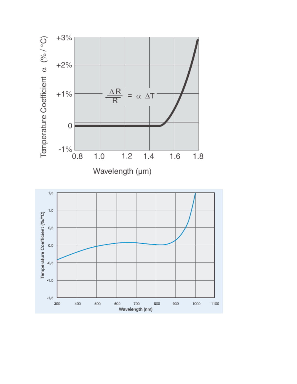
offset power is stable for several minutes. The sensitivity of the phodiode also has temperature
dependence. See Fig 1-2 and Fig 1-3 for the typical temperature sensitivity dependence over the
spectral range for Ge, Si and SiUV.
PH Series Instruction Manual Gentec Electro-Optics Inc. All rights reserved
Page 15
Version 2.3
11
FIG 1-2 TYPICAL GE TEMPERATURE DEPENDENCE VS THE WAVELENGTH
FIG 1-3 TYPICAL SI AND SIUV TEMPERATURE DEPENDENCE VS THE WAVELENGTH
PH Series Instruction Manual Gentec Electro-Optics Inc. All rights reserved
Page 16

Version 2.3
12
SlopeSensySensitivit
LOWdesired
*
__
LOWDESIRED
)(
)(
__
LOWHIGH
LOWHIGH
SensSens
Slope
4.3 SATURATION
The maximum power varies with wavelength, power density and from one diode to another. When
making measurements near the saturation power, you must verify the saturation effect with a
calibrated Filter.
4.3.1 Procedure with a known transmission value filter
Make the measurement with and without the filter.
Your power ratio should be equal to the transmission value of the filter.
4.3.2 Attenuator calibration procedure
Make sure your stable power source is far below the saturation point.
Make the measurement with and without the filter.
The transmission value is the ratio of the measurement with filter / without filter.
4.4 MEASUREMENT OF THE AVERAGE POWER OF A PULSE LASER BEAM
Conditions to be met:
The repetition rate must be at least 5 times the analog Bandwidth (see table IV).
The peak power must not saturate the detector.
To know if the detector is saturated, use procedure 4.3.1. Be careful when making the attenuator
calibration in pulse mode. The peak power must be in the linear region of the photodiode.
Peak power = Energy per pulse / pulse width. Energy per pulse = Average power / repetition rate.
4.5 WAVELENGTH
The photodiode response varies with wavelength. You may select your wavelength with the
Settings/Wavelength menu of the monitor or enter you wavelength in the Settings/Custom menu of
the monitor.
If you decide to use the photo detector without a Gentec-EO monitor, you will have to use the
sensitivity given by the photo detector calibration certificate to calculate the power on you laser beam.
If your wavelength is not given by the calibration certificate, you will have to make a linear
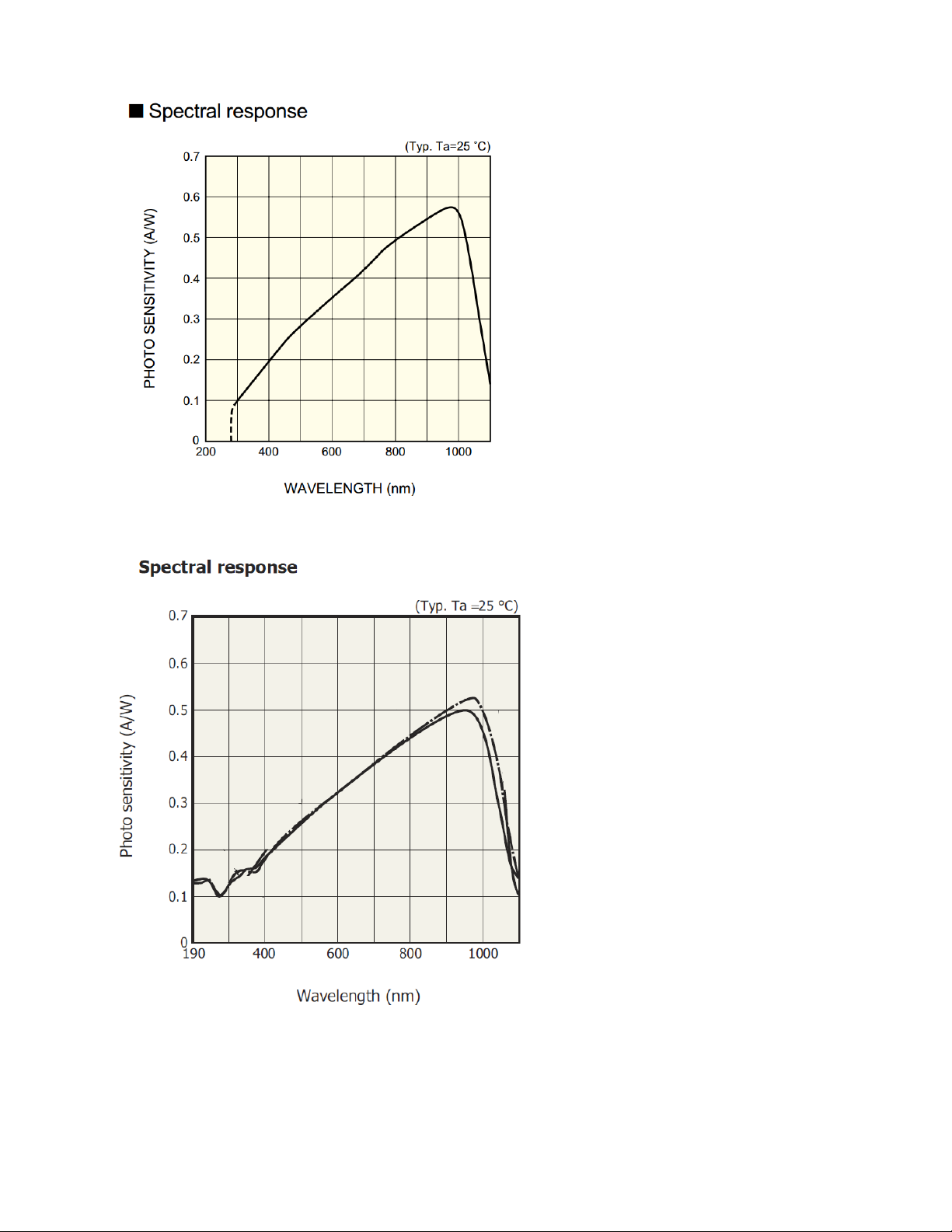
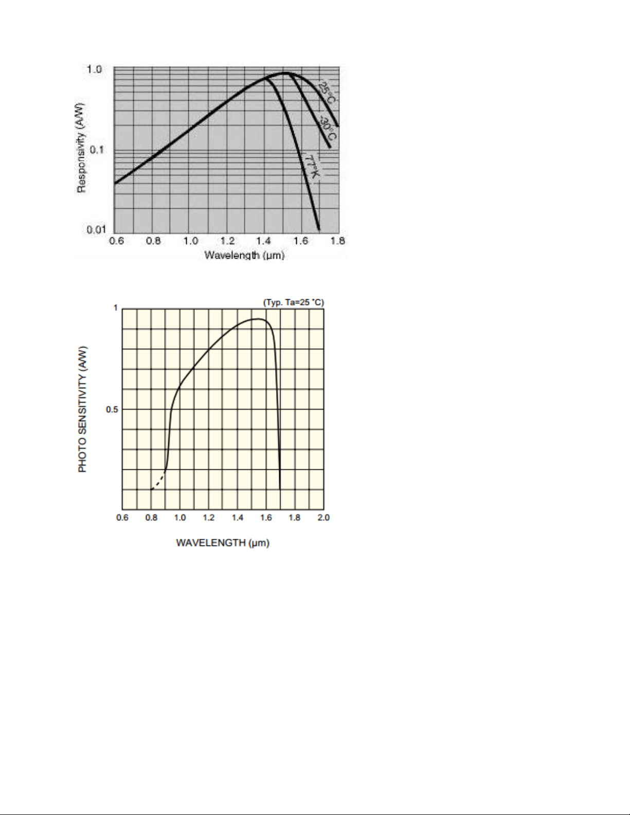
interpolation between two of the available calibration values. Fig. 1-4, Fig. 1-5 and Fig. 1-6 shows
the typical spectral response.
Linear interpolation formula:
Sensitivity
desired_
: The sensitivity at the desired wavelength.
PH Series Instruction Manual Gentec Electro-Optics Inc. All rights reserved
Page 17
Version 2.3
13
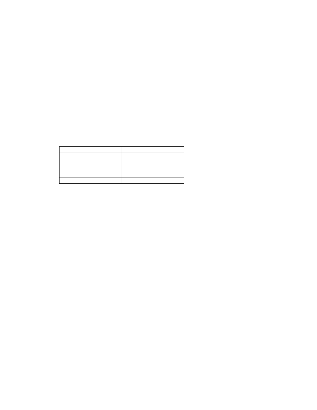
Wavelength (nm)
Sensitivity (A/W)
620
0.32
630
0.35
640
0.37
650
0.40
660
0.43
Slope: The slope of the linear interpolation.
Sens
Sens
LOW
HIGH
DESIRED
: Sensitivity at
LOW_λ
: Sensitivity at
HIGH_λ
LOW
HIGH
.
.
: The next lowest available wavelength near your desired wavelength.
: The next highest available wavelength near your desired wavelength.
: Desired Wavelength.
: The difference between the desired wavelength and the inferior wavelength.
4.5.1 Example
You have a PH100-Si and your laser is at 632.8 nm.
See your CERTIFICATE OF CALIBRATION for the sensitivity of your power detector as a function of
the wavelength.
632.8 nm is between 630 nm and 640 nm therefore,
Sens
Sens
LOW
HIGH
= 0.35 A/W
LOW_λ
= 0.37 A/W
HIGH_λ
= 630 nm
= 640 nm
: 632.8 - 630 = 2.8 nm
Slope: (0.37-0.35)/(640-630) = 0.002
Sensitivity
desired_
: 0.35 + 2.8 * 0.002= 0.356 A/W
PH Series Instruction Manual Gentec Electro-Optics Inc. All rights reserved
Page 18
Version 2.3
14
FIG. 1-4 PH100-SI, PH100-SI-HA TYPICAL SPECTRAL RESPONSE
FIG. 1-5 PH100-SIUV, PH10B-SI, PE10B-SI TYPICAL SPECTRAL RESPONSE
PH Series Instruction Manual Gentec Electro-Optics Inc. All rights reserved
Page 19
Version 2.3
15
FIG. 1-6 PH20-GE, PH5B-GE, PE5B-GE TYPICAL SPECTRAL RESPONSE
FIG. 1-7 PE3B-IN TYPICAL SPECTRAL RESPONSE
PH Series Instruction Manual Gentec Electro-Optics Inc. All rights reserved
Page 20

Version 2.3
16
Appendix A: WEEE directive
1.1 Recycling and separation procedure for WEEE directive 2002/96/EC:
This section is used by the recycling center when the detector reaches its end of life. Breaking
the calibration seal or opening the monitor will void the detector warranty.
The complete Detector contains
1 Detector with wires or DB-15.
1 instruction manual
1 calibration certificate
1 Electronic PCB (Integra option)
1 Plastic enclosure (Integra option)
1.2 Separation:
Paper : Manual and certificate
Wires: Cable Detector.
Printed circuit board: inside the Detector or DB-15, no need to separate (less then 10 cm2).
Aluminum: Detector casing. Inside the integra enclosure, no need to separate (less then 10
cm2).
Aluminum: Detector casing.
Plastic: Integra enclosure.
PH Series Instruction Manual Gentec Electro-Optics Inc. All rights reserved
Page 21
Version 2.3
17
PH Series Instruction Manual Gentec Electro-Optics Inc. All rights reserved
 Loading...