

Page 1
Page 2

Warranty
First Year Warranty
The Gentec-EO thermal power and energy detectors carry a one-year warranty (from date of shipment)
against material and /or workmanship defects when used under normal operating conditions. The
warranty does not cover recalibration or damages related to misuse.
Gentec-EO will repair or replace at its option any wattmeter or joulemeter which proves to be defective
during the warranty period, except in the case of product misuse.
Any unauthorized alteration or repair of the product is also not covered by the warranty.
The manufacturer is not liable for consequential damages of any kind.
In the case of a malfunction, contact the local Gentec-EO distributor or nearest Gentec-EO office to
obtain a return authorization number. Return the material to the appropriate address below.
Contacting Gentec Electro-Optics Inc.
To help us answer your calls more efficiently please have the model number of the detector you are
using ready before calling Customer Support.
All customers:
Gentec-EO, Inc.
445 St-Jean-Baptiste, Suite 160
Quebec, QC, G2E 5N7
Canada
Tel: (418) 651-8003
Fax: (418) 651-1174
Email: [email protected]
Web: www.gentec-eo.com
Lifetime Warranty
Gentec-EO will warranty any thermal power and energy detector head for its lifetime as long as it has
been returned for recalibration annually from the date of shipment. This warranty includes parts and labor
for all routine repairs including normal wear under normal operating conditions.
Gentec-EO will inspect and repair the detector during the annual recalibration. Exceptions to repair at
other times will be at Gentec-EO’s option.
Not included is the cost of annual recalibration or consequential damages from using the detector.
The only condition is that the detector head must not have been subject to unauthorized service or
damaged by misuse. Misuse would include, but is not limited to, laser exposure outside Gentec-EO’s
published specifications, physical damage due to improper handling, and exposure to hostile
environments. Hostile environments would include, but are not limited to excessive temperature,
vibration, humidity, or surface contaminants; exposure to flame, solvents or water; and connection to
improper electrical voltage.
Page 3

Version 5.0 II
TABLE OF CONTENTS
WARRANTY .................................................................................................................... I
First Year Warranty ....................................................................................................................................................i
Lifetime Warranty ........................................................................................................................................................i
TABLE OF CONTENTS .................................................................................................. II
LIST OF ILLUSTRATIONS ............................................................................................ III
1 ULTRA SERIES UP POWER DETECTORS .............................................................. 1
1.1 INTRODUCTION ................................................................................................................................................ 1
1.2 POWER DETECTOR CONNECTORS .............................................................................................................. 2
1.2.1 DB-15 “intelligent” connector ......................................................................................................................... 2
1.2.4 OEM Molex connector (E0 version) ................................................................................................................ 3
1.2.5 Molex connector (MT version) ........................................................................................................................ 4
1.2.6 Molex-BNC (BT version) ................................................................................................................................ 5
1.2.7 Molex connector without amplification or anticipation (M0 version) ............................................................. 6
1.2.8 Trim pot (CP version) ...................................................................................................................................... 6
1.3 ULTRA SERIES UP, XLP SERIES SPECIFICATIONS .................................................................................. 7
1.4 UP CALORIMETER MODE SPECIFICATIONS .......................................................................................... 24
1.5 UP POTENTIOMETER POSITIONS ............................................................................................................... 26
1.6 USING A CUSTOMER-SUPPLIED HEAT SINK ........................................................................................... 27
2 OPERATING INSTRUCTIONS ................................................................................. 30
2.1 WITH ANY GENTEC-EO MONITOR............................................................................................................ 31
2.2 WITHOUT A GENTEC-EO MONITOR ......................................................................................................... 31
2.3 SAFETY OPERATION NOTES.............................................................................. 32
Diffusive surfaces ................................................................................................................................................... 32
Detector temperature while in operation ................................................................................................................. 32
3 DAMAGE TO THE OPTICAL ABSORBER MATERIAL ........................................... 32
APPENDIX A: WEEE DIRECTIVE................................................................................ 33
DECLARATION OF CONFORMITY ............................................................................. 34
APPENDIX B: USING THE XLP12 WITH THE XLP12 FILTER: .................................. 35
APPENDIX C: USING THE XLP12 WITH AN OPTICAL FIBER ADAPTOR: .............. 36
Ultra Series UP Instruction Manual Gentec Electro-Optics Inc. All rights reserved
Page 4

Version 5.0 III
LIST OF ILLUSTRATIONS
FIG. 1-1 DB-15 CONNECTOR PIN-OUT ................................................................................................................... 2
FIG. 1-2 BNC CONNECTOR ...................................................................................................................................... 3
FIG. 1-3 MOLEX CONNECTOR PIN-OUT IN E0 VERSION .................................................................................. 3
FIG. 1-4 MOLEX CONNECTOR PIN-OUT IN MT VERSION ................................................................................. 4
FIG. 1-5 MOLEX CONNECTOR PIN-OUT IN MT-B VERSION ............................................................................. 4
FIG. 1-6 FEMALE MOLEX CONNECTOR KIT FOR MT AND MO VERSIONS .................................................. 4
FIG. 1-7 MOLEX CONNECTOR PIN-OUT IN BT VERSION .................................................................................. 5
FIG. 1-8 MOLEX CONNECTOR PIN-OUT IN M0 VERSION ................................................................................. 6
FIG. 1-9 MAX AVERAGE POWER DENSITY FOR UP WITH H-TYPE ABSORBER AT 1.064 µM. ................. 22
FIG. 1-10 MINIMUM BEAM SIZES FOR UP WITH H-TYPE ABSORBER AT 1.064 µM. .................................. 23
FIG. 1-11 POTENTIOMETER POSITIONS ............................................................................................................. 26
FIG. 1-12 TAPPED HOLE POSITIONS FOR UP12E, WITHOUT PCB ................................................................. 28
FIG 1-13 TAPPED HOLE POSITIONS FOR UP19K ................................................................................................ 28
FIG 1-14 TAPPED HOLE POSITIONS FOR UP25N, UP50N(M), UP55N(M), AND UP60(M) ............................. 29
FIG. 1-15 XLP12 FILTER SPECIFICATIONS .......................................................................................................... 35
FIG. 1-16 USING AN OPTICAL FIBER ADAPTOR ............................................................................................... 36
Ultra Series UP Instruction Manual Gentec Electro-Optics Inc. All rights reserved
Page 5

Version 5.0
1
Unit
Aperture
Exterior
dimensions
Power range
mm
mm
(without amplification)
XLP12
12
73 x 73
1 µW to 3 W
UP12E
12
38 x 38
1 mW to 70 W
UP17P
17
46 x 46
1 mW to 6 W
UP19K,UP10K
(H5 ; H9 ; VR ; W5)
10 ; 19 ; 19 ; 18 ; 17
50 x 50
0.2 mW to 200 W
UP25N(M)
25
89 x 89
3 mW to 350 W
UP25T
25
62.4 x 62.4
10 mW to 250 W
UP50N(M)
50
89 x 89
5 mW to 50 W
UP55N(M)
55
89 x 89
5 mW to 700 W
UP55G
55
120 x 120
15 mW to 600 W
UP55C
55
116 X 116
0.2 W to 2500 W
UP60N(M)
60
89 x 89
5 mW to 700 W
UP60G
60
120 x 120
15 mW to 600 W
1 ULTRA SERIES UP POWER DETECTORS
1.1 INTRODUCTION
The Gentec-EO Ultra Series UP power detector family includes eleven series (XLP12, UP12E,
UP17P, UP19K, UP25N(M), UP25T, UP50N(M), UP55N(M), UP55C, UP60N(M), UP55G, and
UP60G) of opto-thermal sensors with different cooling options (stand alone, heat sink, fan and
water), with or without amplification. The high power surface absorber sensors are designed for use
at high average power densities.
The UP detectors are supplied with a 180 cm length flexible cable with output connection options of
a DB-15 "intelligent" male connector, an Integra USB connector, a BNC connector, a Molex
connector and a BNC/Molex connector. A few exception exist: the UP50N series is available with
BNC/Molex connector on special order only and the XLP12, UP60N(M), and UP60G series are only
supplied with a DB-15 “intelligent” male connector and the Integra USB connector.
NOTE: To eliminate possible damage, do not carry the detector using the connector cable.
The UP detectors may also be supplied with a stand. Be aware that when using a detector with a
heat sink, the fins should always be placed vertically.
For cases where Gentec-EO’s monitors don’t automatically read the wavelength correction factor,
you can use your detector’s “Personal wavelength correctionTM Certificate” to adjust the power you
read to a power corrected for a particular wavelength.
Call your nearest Gentec-EO distributor to replace the sensor disk and/or to recalibrate the head.
For Gentec-EO’s nearest office contact information, see p. ii, Contacting Gentec Electro-Optics
Inc.
Ultra Series UP Instruction Manual Gentec Electro-Optics Inc. All rights reserved
Page 6
Version 5.0
2
1.2 POWER DETECTOR CONNECTORS
1.2.1 DB-15 “intelligent” connector
The DB-15 male "intelligent" connector contains an EEPROM (Electrically Erasable Programmable
Read-Only Memory) with different information such as the model of the detector, the calibration
sensitivity, the applicable scales and the wavelength correction factor for up to 20 wavelengths
related to the Ultra Series UP detector head in use.
This connector, available in the UP without amplification, allows the TPM-300CE, DUO (model of
the detector, calibration sensitivity and scale) and SOLO (model of the detector, calibration
sensitivity, scale and wavelength correction factor) monitors to adjust their characteristics
automatically to the power sensor being connected. No calibration procedure is required when
installing the power heads, allowing for faster set-up.
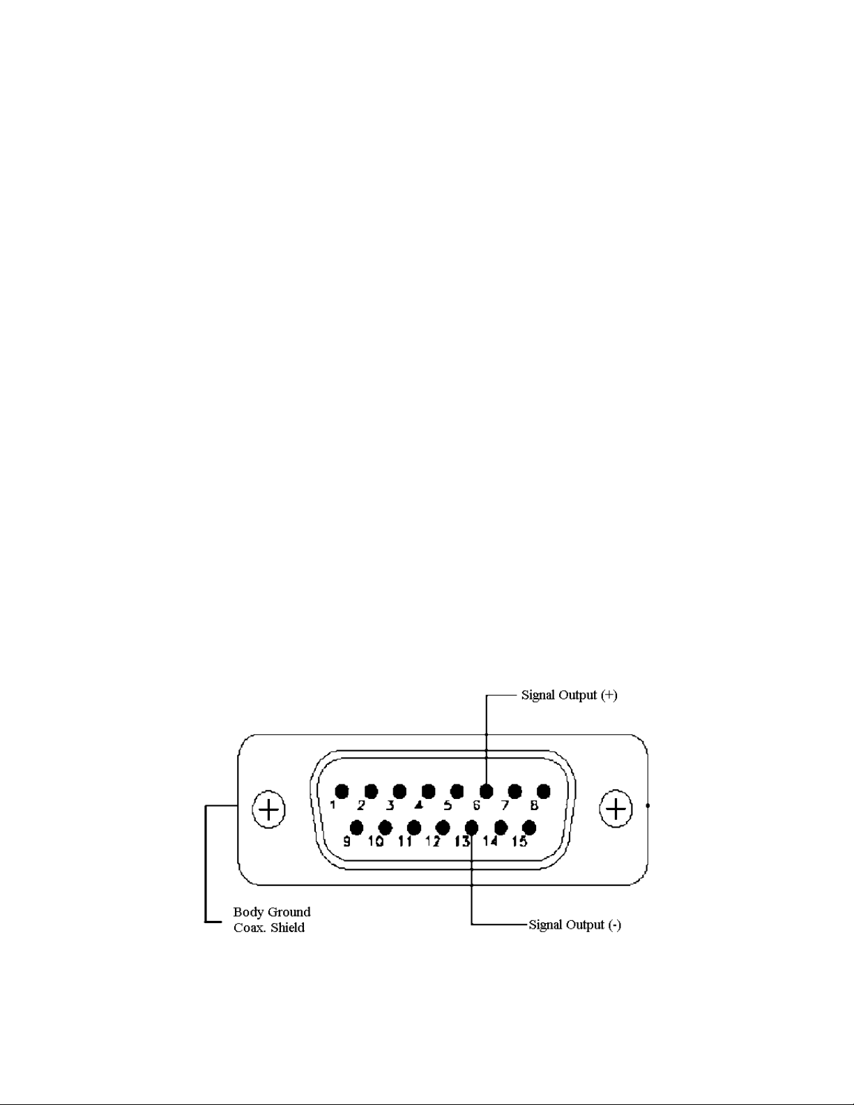
The DB-15 connector pin-out is composed of (see Fig. 1-1):
1- USED BY MONITOR
2- " " " " "
3- " " " " "
4- " " " " "
5- " " " " "
6- SIGNAL (+)
7- USED BY MONITOR
8- " " " " "
9- " " " " "
10- " " " " "
11- " " " " "
12- " " " " "
13- SIGNAL (-)
14- USED BY MONITOR
15- " " " " "
SHELL - BODY GROUND
FIG. 1-1 DB-15 CONNECTOR PIN-OUT
Ultra Series UP Instruction Manual Gentec Electro-Optics Inc. All rights reserved
Page 7
Version 5.0
3
1.2.2 Integra USB connector
The Integra USB Connector is an integrated monitor that allows to plug the head directly into a
computer. It has the same serial commands as the MAESTRO and a few extra one’s (see the PCGentec-EO Manual) and uses the same PC-Gentec-EO software. All specifications are mostly the
same, except for:
Wattmeter and joulemeter heads have a noise ~1.3 x higher.
The risetime of the UP12 head (with anticipation) is slower by 0.2 seconds.
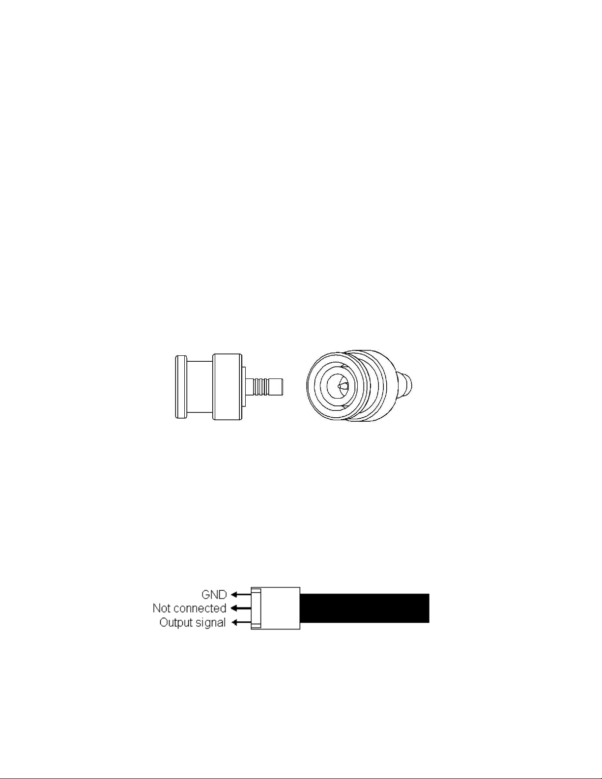
1.2.3 BNC connector
The BNC connector is quick and easy to install and is the best at shielding EMI noise.
The BNC connector allows you to connect the detector directly on an oscilloscope or to a precision
microvoltmeter with the correct load impedance. The connector is available in the UP detectors
without amplification (load impedance: 100 kΩ) and with the Molex connector in the amplified
version (load impedance : 10 MΩ).
FIG. 1-2 BNC CONNECTOR
1.2.4 OEM Molex connector (E0 version)
The Molex female connector is available in the UP19-xxx-H5 and UP12E-xxx-H5 without
amplification (load impedance : 100 kΩ). It allows you to connect to an external PCB board
available at Gentec-EO.
FIG. 1-3 MOLEX CONNECTOR PIN-OUT IN E0 VERSION
Ultra Series UP Instruction Manual Gentec Electro-Optics Inc. All rights reserved
Page 8
Version 5.0
4
1.2.5 Molex connector (MT version)
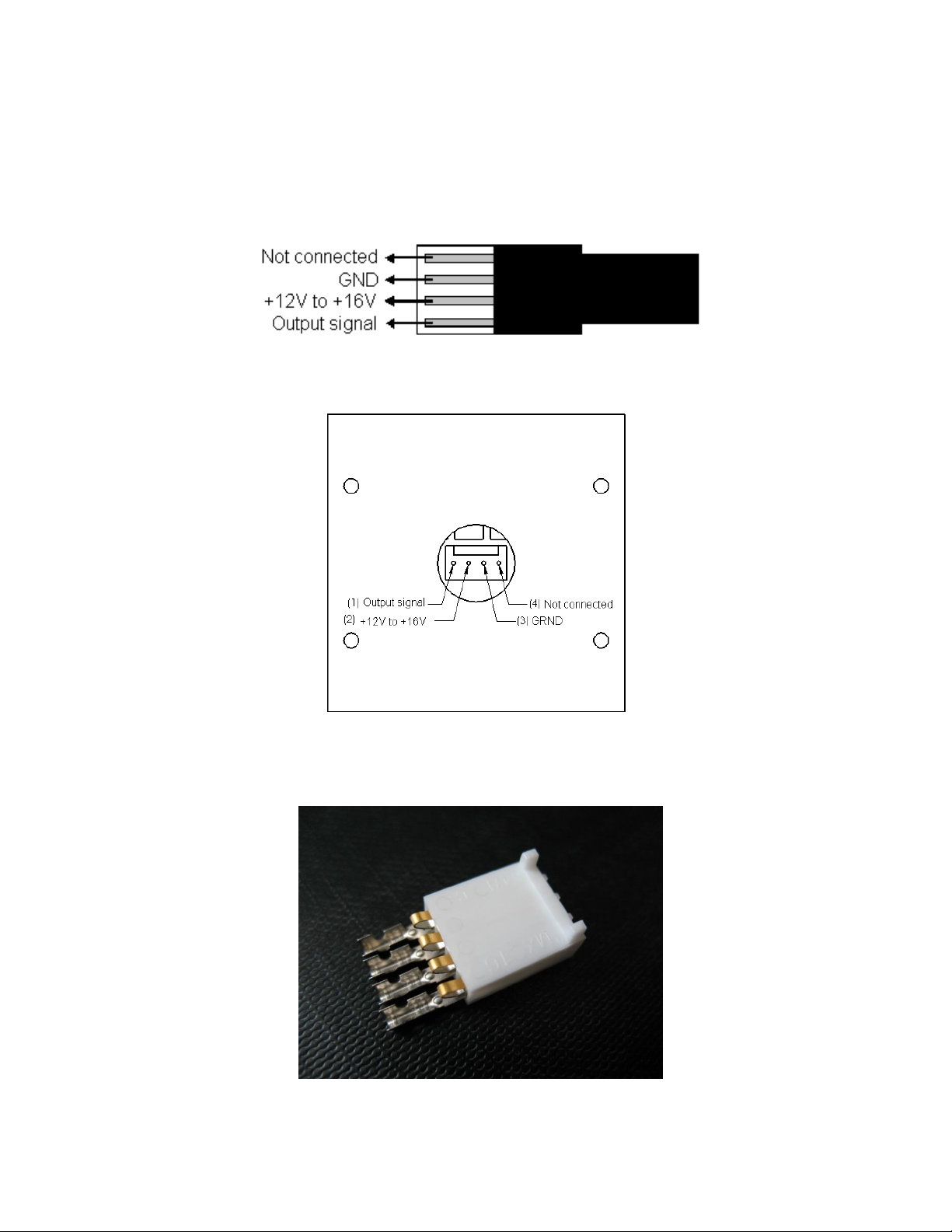
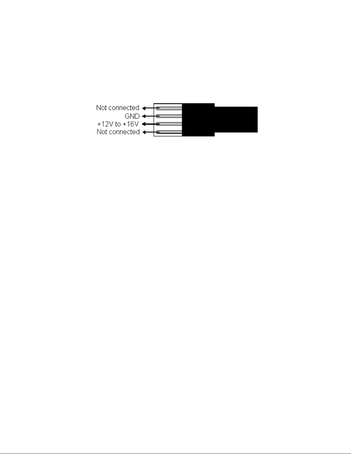
The Molex male connector, available in the UP with amplification, allows you to power the internal
circuit board (PCB) and to read the signal with your own electronics.
The PCB needs +12 to +16V from a regulated power supply but does not need negative voltage.
FIG. 1-4 MOLEX CONNECTOR PIN-OUT IN MT VERSION
FIG. 1-5 MOLEX CONNECTOR PIN-OUT IN MT-B VERSION
Make your own molex cable for use with OEM heads. Product number : 202170
FIG. 1-6 FEMALE MOLEX CONNECTOR KIT FOR MT AND MO VERSIONS
Ultra Series UP Instruction Manual Gentec Electro-Optics Inc. All rights reserved
Page 9
Version 5.0
5
1.2.6 Molex-BNC (BT version)
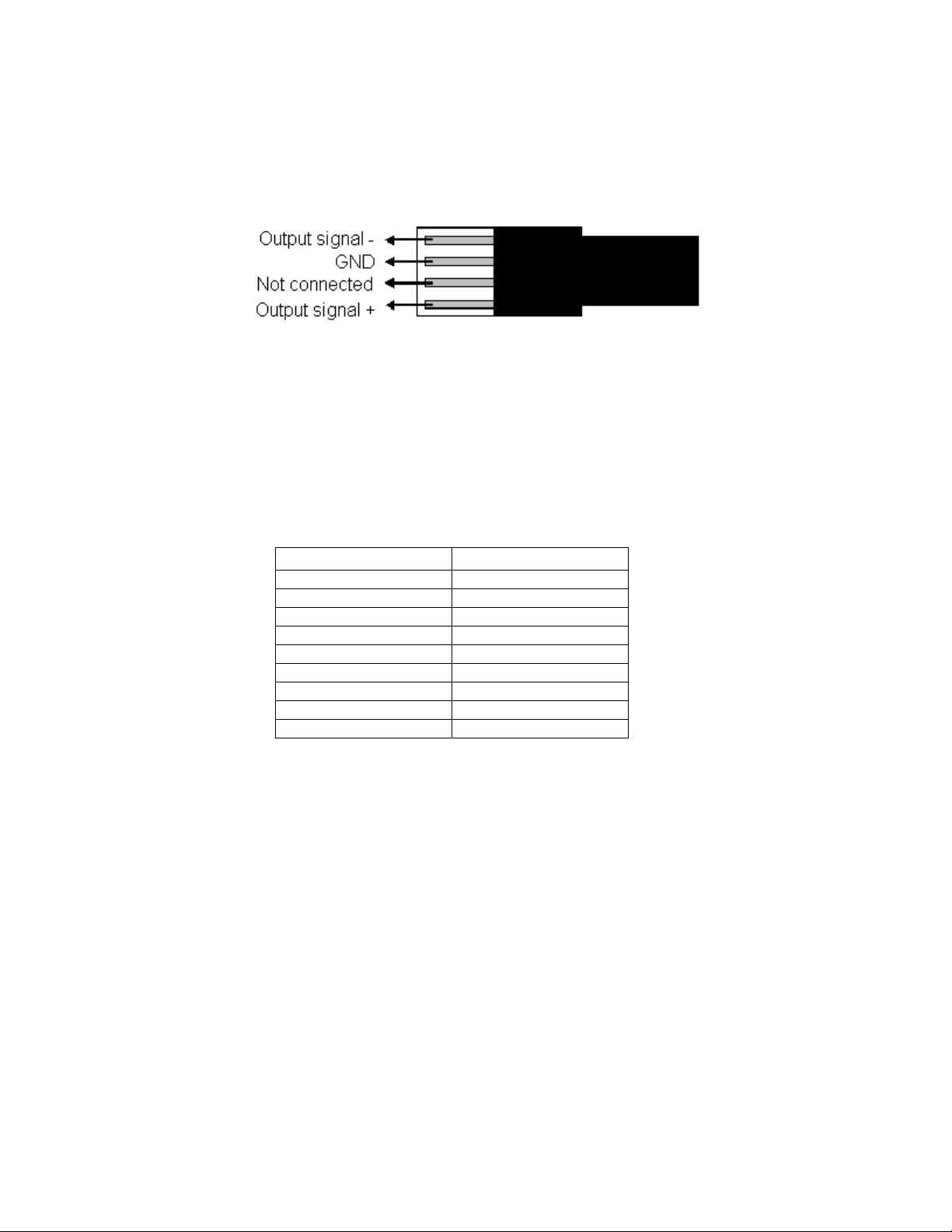
The Molex-BNC connection, available in the UP with amplification, allows you to power the internal
circuit board (PCB) with the Molex connector and to read the signal with the BNC connector (load
impedance : 10 MΩ). The PCB needs +12 to +16V from a regulated power supply but does not
need negative voltage.
FIG. 1-7 MOLEX CONNECTOR PIN-OUT IN BT VERSION
Ultra Series UP Instruction Manual Gentec Electro-Optics Inc. All rights reserved
Page 10
Version 5.0
6
Detector
Sensitivity
UP12E-10S-H5
0.42 mV/W
UP19K-xxx-H5
0.52 mV/W
UP19K-xxx-H9
0.23 mV/W
UP19K-xxx-VR
0.34 mV/W
UP19K-xxx-W5
0.53 mV/W
UP25N-xxx-H9
0.18 mV/W
UP25T-xxx-H12
0.10 mV/W
UP55N-xxx-H9
0.09 mV/W
UP55C-xxx-HD
0.008 mV/W
1.2.7 Molex connector without amplification or anticipation (M0 version)
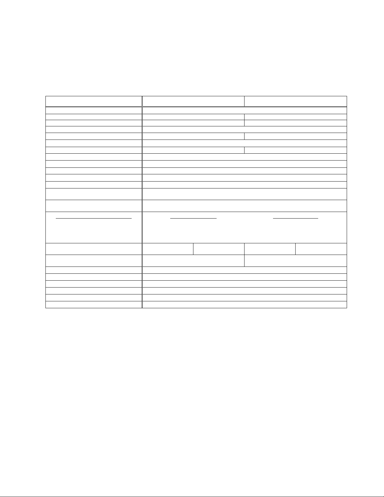
The Molex male connector, available in the UP without amplification, allows you to read the signal
with your own electronics.
FIG. 1-8 MOLEX CONNECTOR PIN-OUT IN M0 VERSION
1.2.8 Trim pot (CP version)
The detector with trim pot and BNC connector (recommended load impedance: 10 MΩ), available in
the UP12E, UP19K, UP25N, UP25T and UP55N without amplification, allows you to have the same
sensitivity for all your detector.
Ultra Series UP Instruction Manual Gentec Electro-Optics Inc. All rights reserved
Page 11
Version 5.0
7
XLP12-…-3S-H2
XLP12-3S-H2
XLPF12-3S-H2
Effective Aperture Diameter
12 mm
Spectral Range
0.19 µm – 20 µm
0.28 µm – 2.1 µm
Calibrated spectral range
0.248 – 2.5 µm and 10.6 µm
b
0.308 – 2.1 µm a
Power Noise Level
c, d
± 0.5 µW
Thermal Drift e
12 µW/oC
6 µW/oC
Typical Rise time (0-95%)
27 s (2.5 s with anticipation)
Typical sensitivity
200 mV/W
180 mV/W
Calibration Uncertainty
± 2.5 %
Linearity with Power
± 2 %
Repeatability (Precision)
± 0.5 %
Power Resolution
± 0.5 %
Max. Average Power
3 W
Max. Average Power (1 min)
(cooling : minimum 3 min)
3 W
Max. Average Power Density
1.064 µm, 1 W CW
1 kW/cm2
Pulsed Laser Damage Thresholds
1.064 µm, 360 µs, 5 Hz
1.064 µm, 7 ns, 10 Hz
532 nm, 7 ns, 10 Hz
266 nm, 7 ns, 10 Hz
Max. Energy Density
5 J/cm2
1 J/cm2
0.6 J /cm
2
0.3 J /cm2
Peak Power Density
14 kW/cm2
143 MW/cm2
86 MW/cm2
43 MW/cm2
Dimensions (H x W x D, in mm)
With isol. tube:
73 x 73 x 72
W/o isol. tube:
73 x 73 x 20
With isol. tube:
73 x 73 x 80
W/o isol. tube:
73 x 73 x 28
Weight
(head only, with isolation tube)
0.312 kg
0.324 kg
Cooling
Heat sink
Recommended load Impedance
100 kΩ
Output Impedance
N. A.
Linearity vs beam dimension
± 0.7 %
PCB electrical supply
N. A.
Max output signal
N. A.
1.3 ULTRA SERIES UP, XLP SERIES SPECIFICATIONS
The following specifications are based on a one-year calibration cycle, an operating temperature of 15 to
28°C and a relative humidity not exceeding 80%. Storage 10 to 65°C and relative humidity not
exceeding 90%.
a
Except 1350 – 1450 nm.
b
The calibrations at 2.1 to 2.5 µm and 10.6 µm are on special request only.
c
Nominal value, actual value depends on electrical noise in the measurement system.
d
Without anticipation. ± 5 µW with anticipation.
e
At 150 µW. 12 μW/°C for XLP12 with SOLO, 50 μW/°C for XLP12 with P-LINK.
Ultra Series UP Instruction Manual Gentec Electro-Optics Inc. All rights reserved
Specifications subject to change without notice.
Page 12
Version 5.0
8
…12-…-3S-VP
XLP12-3S-VP
Effective Aperture Diameter
12 mm
Spectral Range
0.248 – 20 µm
Calibrated spectral range 0.248 – 2.5 µm b
Power Noise Level
c, d
± 0.5 µW
Thermal Drift e
12 µW/oC
Typical Rise time (0-95%)
30 s (3.0 s with anticipation)
Typical sensitivity
220 mV/W
Calibration Uncertainty
± 2.5 % @ 1.064µm
± 3.5 % @ 0.25-2.5µm
Linearity with Power
± 2 %
Repeatability (Precision)
± 0.5 %
Power Resolution
± 0.5 %
Max. Average Power
3 W
Max. Average Power (1 min)
(cooling : minimum 3 min)
3 W
Minimum Repetition Rate
7 Hz with Antipation
1 Hz without Anticipation
Max. Average Power Density
1 W CW
30 W/cm2 @1.064 μm
8 W/cm2 @0.532 μm
4 W/cm2 @0.355 μm
Pulsed Laser Damage Thresholds
1.064 µm, 7 ns, 10 Hz
532 nm, 7 ns, 10 Hz
355 nm, 7 ns, 10 Hz
Max. Energy Density
4 J/cm2
3 J /cm
2
1 J /cm2
Dimensions (H x W x D, in mm)
With isol. tube:
73 x 73 x 72
W/o isol. tube:
73 x 73 x 20
Weight
(head only, with isolation tube)
0.316 kg
Cooling
Heat sink
Recommended load Impedance
100 kΩ
Output Impedance
N. A.
Linearity vs beam dimension
± 0.7 %
PCB electrical supply
N. A.
Max output signal
N. A.
a
Except 1350 – 1450 nm.
b
The calibrations at 2.1 to 2.5 µm and 10.6 µm are on special request only.
c
Nominal value, actual value depends on electrical noise in the measurement system.
d
Without anticipation. ± 5 µW with anticipation.
e
At 150 µW. 12 μW/°C for XLP12 with SOLO, 50 μW/°C for XLP12 with P-LINK.
Ultra Series UP Instruction Manual Gentec Electro-Optics Inc. All rights reserved
Specifications subject to change without notice.
Page 13
Version 5.0
9
b
See graph at the end of this section.
UP10K-2S-H5-L
Without PCB
With PCB
Effective Aperture Diameter
10 mm
Spectral Range
0.19 – 20 µm
Calibrated spectral range a
0.248 – 2.5 µm and 10.6 µm
Power Noise Level
0.2 mW with anticipation
0.05 mW without anticipation
15µW with anticipation and moving
average mode (2 sec)
0.2 mW with anticipation
0.05 mW without anticipation
Typical Rise time (0-95%)
3.0 s (0.6 s with anticipation)
Typical sensitivity
2 mV/W
2 V/W
Calibration Uncertainty
± 2.5 %
Linearity with Power
± 2 %
Repeatability (Precision)
± 0.5 %
Power Resolution
± 0.5 %
Max. Average Power
2 S: 2 W
Max. Average Power (1 min)
(cooling : minimum 3 min)
2 S: 2 W
Max. Average Power Density b
1.064 µm, 2W CW
10.6 µm, 2W CW
36 kW/cm2
11 kW/cm2
Pulsed Laser Damage Thresholds
1.064 µm, 360 µs, 5 Hz
1.064 µm, 7 ns, 10 Hz
532 nm, 7 ns, 10 Hz
266 nm, 7 ns, 10 Hz
Max. Energy Density
5 J/cm2
1.0 J/cm2
0.6 J /cm2
0.3 J /cm2
Peak Power Density
14 kW/cm2
143 MW/cm2
86 MW/cm2
43 MW/cm2
Dimensions (mm)
50(H) x 50(W) x 20.6(D)
50(H) x 50(W) x 25.6(D)
Weight (head only)
2S: 0.13 kg
2S: 0.20 kg
Cooling
Stand alone
Stand alone
Recommended load Impedance
100 kΩ
10 MΩ
Output Impedance
N. A.
≤ 50 Ω
Linearity vs beam dimension
± 0.7 %
PCB electrical supply
N. A.
+ 12 V to + 16 V regulated
Max output signal
N. A.
80 % of PCB electrical supply
a
The calibrations at 2.1 to 2.5 µm and 10.6 µm are on special request only.
Specifications subject to change without notice.
Ultra Series UP Instruction Manual Gentec Electro-Optics Inc. All rights reserved
Page 14
Version 5.0
10
b
See graph at the end of this section.
c
Water temperature ≤ 22°C, 1/8 NPT compression fittings for ¼ inch semi-rigid tube.
Specifications subject to change without notice.
UP12E-…-H5-…
10S / 20H / 70W -H5
Without PCB
10S -H5
With PCB
Effective Aperture Diameter
12 mm
Spectral Range
0.19 – 20 µm
Calibrated spectral range a
0.248 – 2.5 µm and 10.6 µm
Power Noise Level
1 mW
0.25 mW
Typical Rise time (0-95%)
1.6 s (0.3 s with anticipation)
0.3 s (with anticipation)
Typical sensitivity
0.53 mV/W
400 mV/W
Calibration Uncertainty
± 2.5 %
Linearity with Power
± 2 %
Repeatability (Precision)
± 0.5 %
Power Resolution
± 0.5 %
Max. Average Power
10S: 10 W
20H: 20 W
70W: 70 W
10S: 10 W
Max. Average Power (1 min)
(cooling : minimum 3 min)
10S: 20 W
20H: 40 W
70W: 110 W
10S: 20 W
Max. Average Power Density b
1.064 µm, 10W CW
10.6 µm, 10W CW
36 kW/cm2
11 kW/cm2
Pulsed Laser Damage Thresholds
1.064 µm, 360 µs, 5 Hz
1.064 µm, 7 ns, 10 Hz
532 nm, 7 ns, 10 Hz
266 nm, 7 ns, 10 Hz
Max. Energy Density
5 J/cm2
1.0 J/cm2
0.6 J /cm2
0.3 J /cm2
Peak Power Density
14 kW/cm2
143 MW/cm2
86 MW/cm2
43 MW/cm2
Dimensions (mm)
10S: 38(H) x 38 (W) x 14 (D)
20H: 38(H) x 38 (W) x 45 (D)
70W: 38(H) x 38 (W) x 32 (D)
10S: 38(H) x 38 (W) x 36.6 (D)
Weight (head only)
10S: 0.13 kg
20H: 0.15 kg
70W: 0.19 kg
10S: 0.20 kg
Minimum Cooling Flow c
0.5 liter/min
N. A.
Recommended Cooling Flow c
1.0 liter/min
N. A.
Cooling
Heat sink / water
Stand alone
Recommended load Impedance
100 kΩ
10 MΩ
Output Impedance
N. A.
≤ 50 Ω
Linearity vs beam dimension
± 0.7 %
PCB electrical supply
N. A.
+ 12 V to + 16 V regulated
Max output signal
N. A.
80 % of PCB electrical supply
a
The calibrations at 2.1 to 2.5 µm and 10.6 µm are on special request only.
Ultra Series UP Instruction Manual Gentec Electro-Optics Inc. All rights reserved
Page 15
Version 5.0
11
UP17P-6S-H5
UP17P-6S-H5
Effective Aperture Diameter
17 mm
Spectral Range
190 nm – 20 µm
Calibrated spectral range a
0.248 – 2.5 µm and 10.6 µm
Power Noise Level b
1 mW
Typical Rise time (0-95%)
2.5 s (0.8 s with anticipation)
Typical sensitivity c
0.6 mV/W
Calibration Uncertainty d
± 2.5 %
Linearity with Power
± 2 %
Repeatability (Precision)
± 0.5 %
Power Resolution
± 0.5 %
Max. Average Power
6 W
Max. Average Power (1 min)
(cooling : minimum 3 min)
7 W
Max. Average Power Density e
1.064 µm, 10 W CW
10.6 µm, 10 W CW
36 kW/cm2
11 kW/cm2
Pulsed Laser Damage Thresholds
1.064 µm, 360 µs, 5 Hz
1.064 µm, 7 ns, 10 Hz
532 nm, 7 ns, 10 Hz
266 nm, 7 ns, 10 Hz
Max. Energy Density
5 J/cm2
1.0 J/cm2
0.6 J /cm2
0.3 J /cm2
Peak Power Density
14 kW/cm2
143 MW/cm2
86 MW/cm2
43 MW/cm
2
Dimensions (mm)
46H x 46 (W) x 10.7 (D)
Weight (head only)
0.1 kg
Recommended load Impedance
100 kΩ
Output Impedance
N.A.
Linearity vs beam dimension
± 0.5 %
PCB electrical supply
N.A.
Max output signal
N.A.
a
The calibrations at 2.1 to 2.5 µm and 10.6 µm are on special request only.
a
Nominal value, actual value depends on electrical noise in the measurement system.
c
Maximum output voltage = sensitivity x maximum power
d
Including linearity with power
e
See graph at the end of this section
Specifications subject to change without notice.
Ultra Series UP Instruction Manual Gentec Electro-Optics Inc. All rights reserved
Page 16
Version 5.0
12
UP17P-6S-W5
UP17P-6S-W5
Effective Aperture Diameter
17 mm
Spectral Range
190 nm – 10 µm
Calibrated spectral range a
0.248 – 2.5 µm
Power Noise Level b
1 mW
Typical Rise time (0-95%)
5 s (1.4 s with anticipation)
Typical sensitivity
0.6 mV/W
Calibration Uncertainty c
± 2.5 %
Linearity with Power
± 2 %
Repeatability (Precision)
± 0.5 %
Power Resolution
± 0.5 %
Max. Average Power
6 W
Max. Average Power (1 min)
(cooling : minimum 3 min)
7 W
Max. Average Power Density d
1.064 µm, 10 W CW
100 kW/cm2
Pulsed Laser Damage Thresholds
1.064 µm, 150 µs, 5 Hz
1.064 µm, 7 ns, 10 Hz
532 nm, 7 ns, 10 Hz
266 nm, 26 ns, 10 Hz
Max. Energy Density
100 J/cm2
1.1 J/cm2
1.1 J /cm2
0.7 J /cm2
Peak Power Density
667 kW/cm2
157 MW/cm2
157 MW/cm2
27 MW/cm
2
Dimensions (mm)
46(H) x 46(W) x 10.7(D)
Weight (head only)
0.1 kg
Recommended load Impedance
100 kΩ
Output Impedance
N.A.
Linearity vs beam dimension
± 0.5 %
PCB electrical supply
N.A.
Max output signal
N.A.
a
The calibrations at 2.1 to 2.5 µm are on special request only.
b
Nominal value, actual value depends on electrical noise in the measurement system.
c
Including linearity with power
d
See graph at the end of this section
Specifications subject to change without notice.
Ultra Series UP Instruction Manual Gentec Electro-Optics Inc. All rights reserved
Page 17
Version 5.0
13
a
The calibrations at 2.1 to 2.5 µm and 10.6 µm are on special request only
b
See graph at the end of this section.
c
Water temperature ≤ 22°C, 1/8 NPT compression fittings for ¼ inch semi-rigid tube. For the stainless steel water module, the minimum
cooling flow is 1.0 liter/min for power higher than 90 W
Specifications subject to change without notice.
UP19K-…-Hx-…
15S / 30H / 50L / 100DI / 150W -H5
15S / 110F / 150DI / 200W -H9
Without PCB
15S / 30H / 50L / 100DI / 110F / 150W -H5
and 15S / 110F / 150DI / 200W -H9
With PCB
Effective Aperture Diameter
19 mm
Spectral Range
190 nm – 20 µm
Calibrated spectral range a
0.248 – 2.5 µm and 10.6 µm
Power Noise Level
H5: 1 mW, H9: 3 mW
H5: 0.2 mW, H9: 0.6 mW
Typical Rise time (0 - 95 %)
H5: 2.8 s (0.6 s with anticipation)
H9: 4.5 s (1.5 s with anticipation)
H5: 0.5 s (with anticipation)
H9: 1.5 s (with anticipation)
Typical sensitivity
H5: 0.65 mV/W
H9: 0.23 mV/W
15S-H5: 400 mV/W
15S-H9:: 200mV/W
30H: 200 mV/W
50L: 120 mV/W
100DI: 55 mV/W
110F: 55 mV/W
150W: 50 mV/W
150DI: 50 mV/W
200W: 30 mV/W
Calibration Uncertainty
± 2.5 %
Linearity with Power
± 2 %
Repeatability (Precision)
± 0.5 %
Power Resolution
± 0.5 %
Max. Average Power
15S-H5, -H9: 15 W
30H: 30 W
50L: 50 W
100DI (stainless steel): 100 W
110F-H9: 110 W
150W: 150 W
150DI-H9 (stainless steel): 150 W
200W-H9: 200 W a
Max. Average Power (1 min)
(cooling : minimum 3 min)
15S-H5, -H9: 30 W
30H: 60 W
50L: 90 W
100DI (stainless steel): 100 W
110F-H9: 150 W
150W: 190 W
150DI-H9 (stainless steel): 150 W
200W-H9: 200 W a
Max. Average Power Density b
1.064 µm, 10W CW
10.6 µm, 10W CW
H5: 36 kW/cm2, H9: 45 kW/cm2
H5: 11 kW/cm2, H9: 14 kW/cm2
Pulsed Laser Damage Thresholds
1.064 µm, 360 µs, 5 Hz
1.064 µm, 7 ns, 10 Hz
532 nm, 7 ns, 10 Hz
266 nm, 7 ns, 10 Hz
Max. Energy Density
H5: 5 J/cm2, H9: 9 J/cm2
1.0 J/cm2
0.6 J /cm
2
0.3 J /cm2
Peak Power Density
H5: 14 kW/cm2, H9: 25 kW/cm2
143 MW/cm2
86 MW/cm2
43 MW/cm
2
Dimensions (mm)
15S: 50(H) x 50(W) x 20.6(D)
30H: 50(H) x 50(W) x 56.3(D)
50L: 76.2(H) x 76.2(W) x 74.7(D)
100DI: 50(H) x 50(W) x 33(D)
110F: 54.2(H) x 54.2(W) x 55.6(D)
150W: 50(H) x 50(W) x 33(D)
150DI: 50(H) x 50(W) x 33(D)
200W: 50(H) x 50(W) x 33(D)
15S: 50(H) x 50(W) x 25.6(D)
30H: 50(H) x 50(W) x 61.3(D)
50L: 76.2(H) x 76.2(W) x 79.7(D)
100DI: 50(H) x 50(W) x 38(D)
110F: 54.2(H) x 54.2(W) x 60.6(D)
150W: 50(H) x 50(W) x 38(D)
150DI: 50(H) x 50(W) x 38(D)
200W: 50(H) x 50(W) x 38(D)
Weight (head only)
15S: 0.16 kg
30H: 0.21 kg
50L: 0.48 kg
100DI: 0.42 kg
110F: 0.25 kg
150W: 0.24 kg
150DI: 0.42 kg
200W: 0.24 kg
15S: 0.20 kg
30H: 0.25 kg
50L: 0.52 kg
100DI: 0.46 kg
110F: 0.29 kg
150W: 0.28 kg
150DI: 0.46 kg
200W: 0.28 kg
Minimum Cooling Flow c
0.5 liter/min
Recommended Cooling Flow c
1.0 liter/min
Cooling
Heat sink / fan / water
Recommended load Impedance
100 kΩ
10 MΩ
Output Impedance
N. A.
≤ 50 Ω
Linearity vs beam dimension
± 0.5 %
PCB electrical supply
N. A.
+12 to +16 V regulated
Max output signal
N. A.
80 % of PCB electrical supply
Ultra Series UP Instruction Manual Gentec Electro-Optics Inc. All rights reserved
Page 18
Version 5.0
14
UP19K-…-VR-…
UP19K-15S / 30H -VR
Without PCB
Effective Aperture Diameter
18 mm
Spectral Range
0.266 - 2.5 µm
Calibrated spectral range a
0.30 – 2.5 µm
Power Noise Level
2 mW
Typical Rise time (0 - 95 %)
36 s (2.5 s with anticipation)
Typical sensitivity
0.34 mV/W
Calibration Uncertainty
± 2.5 %
Linearity with Power
± 2 %
Repeatability (Precision)
± 0.5 %
Power Resolution
± 0.5 %
Max. Average Power
15S: 15 W
30H: 30 W
Max. Average Power (1 min.)
(cooling : minimum 3 min)
15S: 20 W
30H: 35 W
Max. Average Power Density
1.064µm, 10W CW
700 W/cm2
Pulsed Laser Damage Thresholds
1.064 µm, 7 ns, 10 Hz
532 nm, 7 ns, 10 Hz
266 nm, 7 ns, 10 Hz
1.064 µm, 360 µs, 10 Hz
Max. Energy Density
6 J/cm2
4 J /cm2
1 J /cm2
40 J/cm2
Peak Power Density
860 MW/cm2
570 MW/cm2
143 MW/cm2
111 kW/cm2
Dimension (mm)
15S: 50(H) x 50(W) x 20.6(D)
30H: 50(H) x 50(W) x 56.3(D)
Weight (head only)
15S: 0.16 kg
30H: 0.21 kg
Cooling
Heat sink
Recommended load Impedance
100 kΩ
Output Impedance
N. A.
Linearity vs beam dimension
± 0.5 %
PCB electrical supply
N. A.
Max outpul signal
N. A.
a
The calibrations at 2.1 to 2.5 µm are on special request only
Specifications subject to change without notice.
Ultra Series UP Instruction Manual Gentec Electro-Optics Inc. All rights reserved
Page 19
Version 5.0
15
UP19K-…-W5-…
UP19K-15S / 30H / 50L /
50F / 50W / 50DI -W5
Without PCB
UP19K-15S / 30H / 50L /
50F / 50W / 50DI -W5
With PCB
Effective Aperture Diameter
17 mm
Spectral Range
190 nm – 10 µm
Calibrated spectral range a
0.248 – 2.5 µm
Power Noise Level
1 mW
0.2 mW
Typical Rise time (0-95%)
5 s (1.4 s with anticipation)
1.4 s (with anticipation)
Typical sensitivity
0.65 mV/W
15S: 400 mV/W
30H: 200 mV/W
50L: 120 mV/W
50F: 120 mV/W
50W: 120 mV/W
50DI: 120 mV/W
Calibration Uncertainty
± 2.5 %
Linearity with Power
± 2 %
Repeatability (Precision)
± 0.5 %
Power Resolution
± 0.5 %
Max. Average Power
15S: 15 W
30H: 30 W
50L: 50 W
50F: 50 W
50W: 50 W
50DI (stainless steel): 50 W
Max. Average Power (1 min)
(cooling: minimum 3 min)
15S: 30 W
30H: 60 W
50L: 85 W
50F: 85 W
50W: 85 W
50DI (stainless steel): 85 W
Max. Average Power Density
1.064 µm, 10 W CW
100 kW/cm2
Pulsed Laser Damage Thresholds
1.064 µm, 150 µs, 10 Hz
1.064 µm, 7 ns, 10 Hz
532 nm, 7 ns, 10 Hz
248 nm, 26 ns, 10 Hz
Max. Energy Density
100 J/cm2
1.1 J/cm2
1.1 J /cm2
0.7J /cm2
Peak Power Density
667 kW/cm2
157 MW/cm2
157 MW/cm2
27 MW/cm2
Dimension (mm)
15S: 50(H) x 50(W) x 20.6(D)
30H: 50(H) x 50(W) x 56.3(D)
50L: 76.2(H) x 76.2(W) x 74.7(D)
50F: 54.2(H) x 54.2(W) x 55.6(D)
50W: 50(H) x 50(W) x 33(D)
50DI: 50(H) x 50(W) x 33(D)
15S: 50(H) x 50(W) x 25.6(D)
30H: 50(H) x 50(W) x 61.3(D)
50L: 76.2(H) x 76.2(W) x 79.7(D)
50F: 54.2(H) x 54.2(W) x 60.6(D)
50W: 50(H) x 50(W) x 38(D)
50DI: 50(H) x 50(W) x 38(D)
Weight (head only)
15S: 0.16 kg
30H: 0.21 kg
50L: 0.48 kg
50F: 0.25 kg
50W: 0.24 kg
50DI: 0.42 kg
15S: 0.20 kg
30H: 0.25 kg
50L: 0.52 kg
50F: 0.29 kg
50W: 0.28 kg
50DI: 0.46 kg
Minimum Cooling Flow b
0.5 liter/min
Recommended Cooling Flow b
1.0 liter/min
Cooling
Heat sink / fan / water
Recommended load Impedance
100 kΩ
10 MΩ
Output Impedance
N. A.
≤ 50 Ω
Linearity vs beam dimension
± 0.5 %
PCB electrical supply
N. A.
+12 to +16 V regulated
Max outpul signal
N. A.
80 % of PCB electrical supply
a
The calibrations at 2.1 to 2.5 µm are on special request only.
b
Water temperature ≤ 22°C, 1/8 NPT compression fittings for ¼ inch semi-rigid tube.
Specifications subject to change without notice.
Ultra Series UP Instruction Manual Gentec Electro-Optics Inc. All rights reserved
Page 20
Version 5.0
16
UP25N(M)-…-Hx-
…
UP25N-40S / 100H -H9
UP25N-250F-H12
UP25M-350W-H12
Without PCB
UP25N-40S / 100H -H9
UP25N-250F-H12
UP25M-350W-H12
With PCB
Aperture Diameter
25 mm
Spectral Range
190 nm - 20 µm
Calibrated spectral range a
0.248 – 2.5 µm and 10.6 µm
Power Noise Level
H9: 3 mW
H12: 10 mW
40S / 100H: 1 mW
250F-H12: 10 mW
350W-H12: 10 mW
Typical Rise Time (0 – 95 %)
H9: 5 s (1.3 s with anticipation)
H12: 7.9 s (1.3 s with anticipation)
H9: 1.3 s (with anticipation)
H12: 2 s (with anticipation)
Typical sensitivity
H9: 0.23 mV/W
H12: 0.1 mV/W
40S-H9: 150 mV/W
100H-H9: 60 mV/W
250F-H12: 24 mV/W
350W-H12: 24 mV/W
Calibration Uncertainty
± 2.5 %
Linearity with Power
± 2 %
Repeatability (Precision)
± 0.5 %
Power Resolution
± 0.5 %
Max. Average Power
40S: 40 W
100H: 100 W
250F: 250 W
350W: 350 W
Max. Average Power (1 min)
(cooling : minimum 3 min)
40S: 80 W
100H: 200 W
250F: 300 W
350W: 350 W
Max. Average Power Density b
1.064 µm, 10 W CW
10.6 µm, 10 W CW
45 kW/cm2
14 kW/cm2
Pulsed Laser Damage Thresholds
1.064 µm, 360 µs, 5 Hz
1.064 µm, 7 ns, 10 Hz
532 nm, 7 ns, 10 Hz
266 nm, 7 ns, 10 Hz
Max. Energy Density
9 J/cm2
1.0 J/cm2
0.6 J/cm
2
0.3 J/cm2
Peak Power Density
25 kW/cm2
143 MW/cm2
86 MW/cm2
43 MW/cm2
Dimension (mm)
40S: 89(H) x 89(W) x 32(D)
100H: 89(H) x 89(W) x 106(D)
250F: 89(H) x 89(W) x 116(D)
350W: 89(H) x 89(W) x 40(D)
Weight (head only)
40S: 0.68 kg
100H: 0.99 kg
250F: 1.44 kg
350W: 0.87 kg
Minimum Cooling Flow c
1.5 liter/min
Cooling
Heat sink / Fan / Water
Recommended Load Impedance
> 100 kΩ
10 MΩ
Output Impedance
N. A.
≤ 50 Ω
Linearity vs Beam Dimension
± 0.5 %
PCB Electrical Supply
N. A.
+12 V to +16 V regulated
Max Outpul Signal
N. A.
80 % of PCB electrical supply
a
The calibrations at 2.1 to 2.5 µm and 10.6 µm are on special request only
b
See graph at the end of this section.
c
Water temperature ≤ 22°C, 1/8 NPT compression fittings for ¼ inch semi-rigid tube.
Specifications subject to change without notice.
Ultra Series UP Instruction Manual Gentec Electro-Optics Inc. All rights reserved
Page 21
Version 5.0
17
UP25T-…-Hx-…
UP25T-15S / 250W-H12
Without PCB
Aperture Diameter
25 mm
Spectral Range
190 nm - 20 µm
Calibrated spectral range a
0.248 – 2.5 µm and 10.6 µm
Power Noise Level
10 mW
Typical Rise Time (0-95%)
7.9 s
(1.3 s with anticipation)
Typical sensitivity
0.1 mV/W
Calibration Uncertainty
± 2.5%
Linearity with Power
± 2%
Repeatability (Precision)
± 0.5%
Power Resolution
± 0.5%
Max. Average Power
15S: 15 W
250W: 250 W
Max. Average Power (1 min.)
(cooling : minimum 3 min)
15S: 15 W
250W: 250 W
Max. Average Power Density b
1.064µm, 10W CW
10.6 µm, 10W CW
45 kW/cm2
14 kW/cm2
Pulsed Laser Damage Thresholds
1.064 µm, 360 µs, 5 Hz
1.064 µm, 7 ns, 10 Hz
532 nm, 7 ns, 10 Hz
266 nm, 7 ns, 10 Hz
Max. Energy Density
9 J/cm2
1.0 J/cm
2
0.6 J /cm2
0.3 J /cm2
Peak Power Density
25 kW/cm2
143 MW/cm
2
86 MW/cm2
43 MW/cm2
Dimension (mm)
62.4(H) x 62.4(W) x 38.1(D)
Weight (head only)
15S: 0.31 kg
250W: 0.33 kg
Minimum Cooling Flow c
15S: Stand alone
250W: 1.5 liter/min
Cooling
15S: Stand alone
250W: water
Recommended load Impedance
> 100 kΩ
Output Impedance
N. A.
Linearity vs beam dimension
± 0.5 %
PCB electrical supply
N. A.
Max outpul signal
N. A.
a
The calibrations at 2.1 to 2.5 µm and 10.6 µm are on special request only
b
See graph at the end of this section.
c
Water temperature ≤ 22°C, 1/8 NPT compression fittings for ¼ inch semi-rigid tube.
Specifications subject to change without notice.
Ultra Series UP Instruction Manual Gentec Electro-Optics Inc. All rights reserved
Page 22
Version 5.0
18
UP50N(M)-…-W9-
...
UP50N-40S / 50H -W9
UP50M-50W -W9
Without PCB
UP50N-40S / 50H -W9
UP50M-50W -W9
With PCB
Aperture Diameter
50 mm
Spectral Range
190 nm - 10 µm
Calibrated spectral range a
0.248 – 2.5 µm
Power Noise Level
5 mW
40S / 50H / 50W: 3 mW
Typical Rise Time (0 – 95 %)
16 s (3.5 s with anticipation)
16 s (3.5 s with anticipation)
Typical sensitivity
0.12 mV/W
40S: 150 mV/W
50H: 120 mV/W
50W: 120 mV/W
Calibration Uncertainty
± 2.5 %
Linearity with Power
± 2 %
Repeatability (Precision)
± 0.5 %
Power Resolution
± 0.5 %
Max. Average Power
40S: 40 W
50H: 50 W
50W: 50 W
Max. Average Power
(1 min.)
(cooling : minimum 3 min)
40S: 80 W
50H: 85 W
50W: 85 W
Max. Average Power Density
1.064µm, 10W CW
100 kW/cm2
Pulsed Laser Damage Thresholds
1.064 µm, 150 µs, 5 Hz
1.064 µm, 7 ns, 10 Hz
532 nm, 7 ns, 10 Hz
248 nm , 26 ns, 10 Hz
Max. Energy Density
100 J/cm2
1.1 J/cm2
1.1 J /cm
2
0.7J /cm2
Peak Power Density
667 kW/cm2
157 MW/cm2
157 MW/cm2
27 MW/cm2
Dimension (mm)
40S: 89(H) x 89(W) x 32(D)
50H: 89(H) x 89(W) x 106(D)
50W: 89(H) x 89(W) x 40(D)
Weight (head only)
40S: 0.62 kg
50H: 0.93 kg
50W: 0.81 kg
Minimum Cooling Flow b
1 liter/min
Cooling
Heat sink / Fan / Water
Recommended load Impedance
> 100 kΩ
10 MΩ
Output Impedance
N. A.
≤ 50 Ω
Linearity vs beam dimension
± 0.5 %
PCB electrical supply
N. A.
+12 to +16 V regulated
Max outpul signal
N. A.
80 % of PCB electrical supply
a
The calibrations at 2.1 to 2.5 µm are on special request only.
b
Water temperature ≤ 22°C, 1/8 NPT compression fittings for ¼ inch semi-rigid tube.
Specifications subject to change without notice.
Ultra Series UP Instruction Manual Gentec Electro-Optics Inc. All rights reserved
Page 23
Version 5.0
19
UP55N(M)-…-Hx-
…
UP60N(M)-…-Hx-
…
UP55N-40S / 100H -H9
UP55N-300F -H12
UP55N-300DI -H12
UP55M-500W -H12
UP55M-700W -HD
Without PCB
UP55N-40S / 100H -H9
UP55N-300F -H12
UP55N-300DI -H12
UP55M-500W -H12
UP55M-700W -HD
With PCB
UP60N-40S / 100H -H9
UP60N-300F -H12
UP60N-300DI -H12
UP60M-500W -H12
UP60M-700W -HD
Without PCB
Aperture Diameter
55 mm
60 mm
Spectral Range
190 nm - 20 µm
Calibrated spectral range a
0.248 – 2.5 µm and 10.6 µm
Power Noise Level
H9: 5 mW
H12: 15 mW
HD: 45mW
H9: 2 mW
H12: 15 mW
HD: 45mW
H9: 5 mW
H12: 15 mW
HD: 45mW
Typical Rise Time (0 - 95 %)
H9: 11 s (2 s with anticipation)
H12: 18 s (2 s with anticipation)
HD: 14 s(2 s with anticipation)
H9: 2 s (with anticipation)
H12: 3 s (with anticipation)
HD: 5s (with anticipation)
H9: 11 s (2 s with anticipation)
H12: 18 s (2 s with anticipation)
HD: 14 s(2 s with anticipation)
Typical sensitivity
H9: 0.12 mV/W
H12: 0.06 mV/W
HD: 0.03mV/W
40S: 150 mV/W
100H: 60 mV/W
300F: 20 mV/W
300DI : 20mV/W
500W: 15 mV/W
700W: 8 mV/W
H9: 0.12 mV/W
H12: 0.06 mV/W
HD: 0.03mV/W
Calibration Uncertainty
± 2.5 %
Linearity with Power
± 2 %
Repeatability (Precision)
± 0.5 %
Power Resolution
± 0.5 %
Max. Average Power
40S: 40 W
100H: 100 W
300F: 300 W
300DI : 300W
500W: 500 W
700W: 700 W
Max. Average Power
(1 min.)
(cooling : minimum 3 min)
40S: 80 W
100H: 200 W
300F: 300 W
300DI : 300W
500W: 500 W
700W: 700 W
Max. Average Power Density b
1.064 µm, 10 W CW
10.6 µm, 10 W CW
45 kW/cm2
14 kW/cm2
Pulsed Laser Damage Thresholds
1.064 µm, 360 µs, 5 Hz
1.064 µm, 7 ns, 10 Hz
532 nm, 7 ns, 10 Hz
266 nm, 7 ns, 10 Hz
Max. Energy Density
9 J/cm2
1.0 J/cm2
0.6 J/cm
2
0.3 J/cm2
Peak Power Density
25 kW/cm2
143 MW/cm2
86 MW/cm2
43 MW/cm2
Dimension (mm)
40S: 89(H) x 89(W) x 32(D)
100H: 89(H) x 89(W) x 106(D)
300F: 89(H) x 89(W) x 116(D)
300DI : 89(H) x 89(W) x 44(D)
500W: 89(H) x 89(W) x 40(D)
700W: 89(H) x 89(W) x 40(D)
Weight (head only)
40S: 0.62 kg
100H: 0.93 kg
300F: 1.41 kg
300DI :1.68 kg
500W: 0.81 kg
700W: 0.90 kg
Minimum Cooling Flow c
1.5 liter/min
Cooling
Heat sink / Fan / Water
Recommended load Impedance
> 100 kΩ
10 MΩ
> 100 kΩ
Output Impedance
N. A.
≤ 50 Ω
N. A.
Linearity vs beam dimension
± 0.5 %
PCB electrical supply
N. A.
+12 V to +16 V regulated
N. A.
Max outpul signal
N. A.
80 % of PCB electrical
supply
N. A.
a
The calibrations at 2.1 to 2.5 µm and 10.6 µm are on special request only.
b
See graph at the end of this section.
c
Water temperature ≤ 22°C, 1/8 NPT compression fittings for ¼ inch semi-rigid tube. For the stainless steel water module, the minimum
cooling flow is 1.0 liter/min for power higher than 90 W.
Ultra Series UP Instruction Manual Gentec Electro-Optics Inc. All rights reserved
Page 24
Version 5.0
20
Specifications subject to change without notice.
UP55N(M)-…-VR-…
UP55N-50S/100H/150F-VR
UP55M-200W-VR
Without PCB
UP55N-50S/100H/150F-VR
UP55M-200W-VR
With PCB
Aperture Diameter
55 mm
Spectral Range
300 nm – 2.5 µm
Calibrated spectral range a
0.30 – 2.5 µm
Power Noise Level
15 mW
Typical Rise Time (0 - 95 %)
4 s
50 s (without anticipation)
5 s (with anticipation)
Typical sensitivity
0.04 mV/W
50S : 120 mV/W
100 H : 60 mV/W
150 F : 40 mV/W
200 W : 30 mV/W
Calibration Uncertainty
± 2.5 %
Linearity with Power
± 2 %
Repeatability (Precision)
± 0.5 %
Power Resolution
± 0.5 %
Max. Average Power
50S : 50 W
100H : 100 W
150F : 150 W
200W : 200 W
Max. Average Power
(1 min.)
(cooling : minimum 3 min)
50S : 50 W
100H : 100 W
150F : 150 W
200W : 200 W
Max. Average Power Density b
1.064 µm, 10 W CW
700 W/cm2
Pulsed Laser Damage Thresholds
1.064 µm, 7 ns, 10 Hz
532 nm, 7 ns, 10 Hz
266 nm, 7 ns, 10 Hz
1.064 µm, 360 µs, 5 Hz
Max. Energy Density
6 J/cm2
4 J/cm2
1 J/cm
2
40 J/cm2
Peak Power Density
860 MW/cm2
570 MW/cm
2
143 MW/cm
2
111 kW/cm2
Dimension (mm)
50S : 89(H) x 89(W) x 32(D)
100H : 89(H) x 89(W) x 106(D)
150F : 89(H) x 89(W) x 116(D)
200W : 89(H) x 89(W) x 44(D)
Weight (head only)
50S : 0.62 Kg
100H : 0.93 Kg
150F : 1.41 Kg
200W : 0.84 Kg
Minimum Cooling Flow c
1 liter/min
Cooling
Heat sink / Fan / Water
Recommended load Impedance
> 100 kΩ
10 MΩ
Output Impedance
N. A.
≤ 50 Ω
Linearity vs beam dimension
± 0.5 %
PCB electrical supply
N. A.
+12 V to +16 V regulated
Max outpul signal
N. A.
80 % of PCB electrical supply
a
The calibrations at 2.1 to 2.5 µm are on special request only.
b
See graph at the end of this section.
c
Water temperature ≤ 22°C, 1/8 NPT compression fittings for ¼ inch semi-rigid tube.
Specifications subject to change without notice.
Ultra Series UP Instruction Manual Gentec Electro-Optics Inc. All rights reserved
Page 25
Version 5.0
21
UP55C-2.5KW-HD
UP55C-2.5KW-HD
Without PCB
Effective Aperture Diameter
55 mm
Spectral Range
0.19 µm - 20 µm
Calibrated spectral range a
0.248 – 2.5 µm and 10.6 µm
Power Noise Level
± 0.2 W
Typical Rise time (0 - 95 %)
3.5 s (25 s without anticipation)
Typical sensitivity
8 µV/W
Calibration Uncertainty
± 2.5 %
Linearity with Power
± 2 %
Repeatability (Precision)
± 0.5 %
Max. Average Power
2500 W
Max. Average Power Density
1.064 µm, 500W CW
1.064 µm, 1500W CW
1.064 µm, 2500W CW
9.0 kW/cm
2
7.0 kW/cm2
6.0 kW/cm2
Pulsed Laser Damage Thresholds
1.064 µm, 7 ns, 10 Hz
532 µm, 7 ns, 10 Hz
Max. Energy Density
1.0 J/cm2
0.6 J/cm2
Peak Power Density
143 MW/cm2
86 MW/cm2
Dimension (mm)
116(H) x 116(W) x 48(D)
Weight (head only)
1.95 kg
Cooling
Water
Recommended Cooling Flow b 3-4 liter/min
Recommended load Impedance
100 kΩ
Output Impedance
N. A.
Linearity vs beam dimension
± 1 %
PCB electrical supply
N. A.
Max outpul signal
N. A.
b
Water temperature ≤ 22°C, 1/8 NPT compression fittings for ¼ inch semi-rigid tube.
Specifications subject to change without notice.
a
The calibrations at 2.1 to 2.5 µm and 10.6 µm are on special request only.
Ultra Series UP Instruction Manual Gentec Electro-Optics Inc. All rights reserved
Page 26
Version 5.0
22
UP55G-…-HX-…
UP60G-…-HX-…
UP55G-500F-H12
UP55G-600F-HD
Without PCB
UP60G-400F-H12
UP60G-500F-H12
Without PCB
Aperture Diameter
55 mm
60 mm
Spectral Range
190 nm - 20 µm
Calibrated spectral range a
0.248 – 2.5 µm and 10.6 µm
Power Noise Level
H12: 15 mW
HD: 45 mW
Typical Rise Time (0 – 95 %)
H12: 16.6 s (2.8 s with anticipation)
HD: 14 s (2.8 s with anticipation)
Typical sensitivity
H12: 0.06 mV/W
HD: 0.03 mV/W
Calibration Uncertainty
± 2.5%
Linearity with Power
± 2%
Repeatability (Precision)
± 0.5%
Power Resolution
± 0.5%
Max. Average Power
H12: 500 W
HD: 600 W
H12: 400 W
HD: 500 W
Max. Average Power (1 min.)
H12: 500 W
HD: 600 W
H12: 400 W
HD: 500 W
Max. Average Power Density b
1.064 µm, 10 W, CW
1.064 µm, 500 W, CW
45 kW/cm2
8 kW/cm2
Pulsed Laser Damage Thresholds
1.064 µm, 360 µs, 5 Hz
1.064 µm, 7 ns, 10 Hz
532 nm, 7 ns, 10 Hz
266 nm, 7 ns, 10 Hz
Max. Energy Density
9 J/cm2
1.0 J/cm2
0.6 J/cm
2
0.3 J/cm2
Peak Power Density
25 kW/cm2
143 MW/cm
2
86 MW/cm
2
43 MW/cm2
Dimensions (mm)
120(H) x 120(W) x 135(D)
Weight (head only)
2.75 kg
Cooling
Fan
Recommended load Impedance
> 100 kΩ
Output Impedance
N. A.
Linearity vs beam dimension
± 0.5 %
PCB electrical supply
N. A.
Max outpul signal
N. A.
a
The calibrations at 2.1 to 2.5 µm and 10.6 µm are on special request only.
b
See graph at the end of this section.
Specifications subject to change without notice.
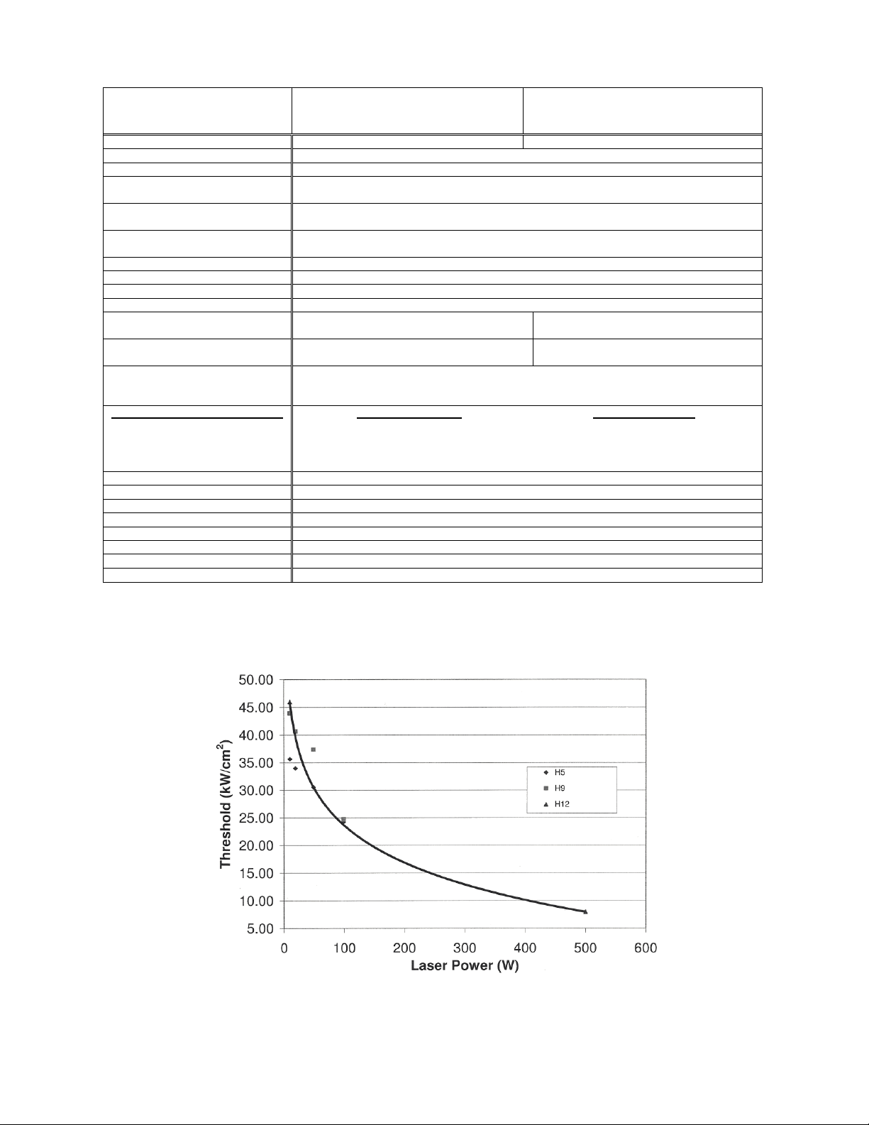
FIG. 1-9 MAX AVERAGE POWER DENSITY FOR UP WITH H-TYPE ABSORBER AT 1.064 µM.
Ultra Series UP Instruction Manual Gentec Electro-Optics Inc. All rights reserved
Page 27
Version 5.0
23
0
100
200
300
400
500
600
700
0 2 4 6 8 10 12
Power [W]
Beam diameter [mm]
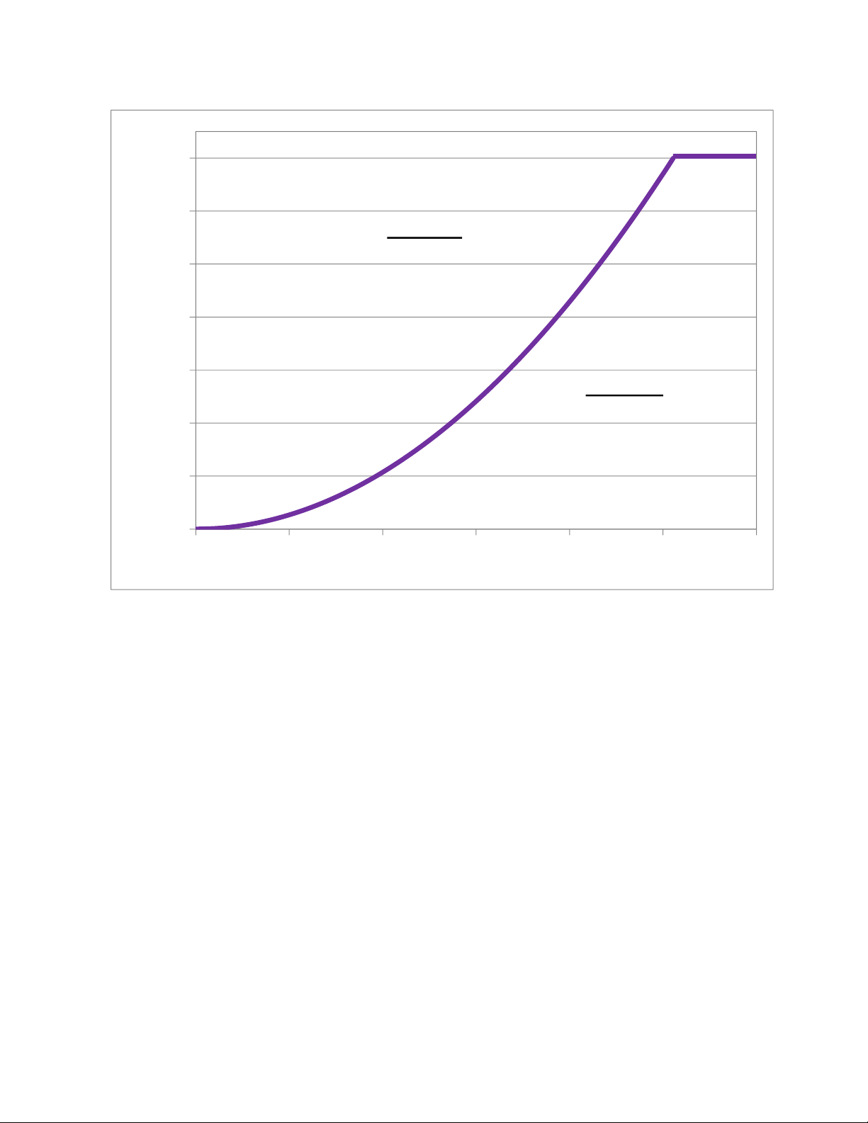
The absorber will be damaged if it is
used in this zone
Safe zone
(If the applied power does not
exceed the maximum power in
the specification)
FIG. 1-10 MINIMUM BEAM SIZES FOR UP WITH H-TYPE ABSORBER AT 1.064 µM.
Ultra Series UP Instruction Manual Gentec Electro-Optics Inc. All rights reserved
Page 28
Version 5.0
24
XLP(F)
-…H2
UP12E
-…H5
UP10K
-…H5
UP17P
-…H5
UP17P
-…-
W5
UP19K
-…H5
UP19K
-…H9
UP19K
-…-
VR
UP19K
-…-
W5
Typical sensitivity
mV/J
25
F : 22.5
0.84
2.3
0.7
0.2
0.65
0.23
0.10
0.33
Power sensitivity /
Energy sensitivity
J/W 8 0.63
0.86
0.86 3 0.99 1 3.4
2
Typical rise time in
calorimeter mode
ms
1000
150
264
328
575
264
264
270
400
Minimum repetition
period
sec
16
1.5 4 4 5 4 4 4.5
5
Maximum pulse
width
ms
300
50
88
88
133
88
88
90
133
Maximum
measurable energya
J 5 5 3 15
200
15
25
40
200
Noise equivalent
energy
mJ
0.012
20 2 20
20
20
60
20
23
Accuracy
%
± 5
± 5
± 5
± 5
± 5%
± 5%
± 5%
± 5
± 5
UP25N,
-…H9
UP25N,
UP25M
-…-
H12
UP25T
-…-
H12
UP50N,
UP50M
-…W9
UP55N,
UP60N
-…-
H9
UP55N
UP55M
-...VR
UP55N,
UP55M,
UP60N,
UP60M
-…-
H12
Typical sensitivity
mV/J
0.14
0.05
0.05
0.020
0.028
0.010
0.015
Power sensitivity /
Energy sensitivity
J/W
1.67
2.19
2.19
5.28
4.25
4.25
4.46
Typical rise time in
calorimeter mode
ms
370
1300
1300
1400
1300
1300
1600
Minimum repetition
period
sec
4.6
11.5
11.5
11.1
11.1
11.1
12
Maximum pulse
width
ms
123
390
390
467
433
433
430
Maximum
measurable energya
J
40
40
40
500
200
500
200
Noise equivalent
energy
mJ
200
200
200
250
250
250
250
Accuracy
%
± 5
± 5
± 5%
± 5%
± 5%
± 5%
± 5
1.4 UP CALORIMETER MODE SPECIFICATIONS
The UP Ultra Series has an optional mode that is called calorimeter mode. It allows you to measure
single shot pulse energy. This mode is accessible when you use a UP with a Gentec-EO monitor or
with your own data acquisition system. For more information, refer to the monitor’s instruction
manual or call Customer Support at Gentec-EO, see p. ii, Contacting Gentec Electro-Optics Inc.
Ultra Series UP Instruction Manual Gentec Electro-Optics Inc. All rights reserved
Page 29
Version 5.0
25
UP55G,
UP60G
-…-
H12
UP55M,
UP55G,
UP60M,
UP60G
-…-
HD
Typical sensitivity
mV/J
0.013
0.008
Power sensitivity /
Energy sensitivity
J/W
4.62
4.46
Typical rise time in
calorimeter mode
ms
1800
1600
Minimum repetition
period
sec
14.3
12
Maximum pulse
width
ms
433
430
Maximum
measurable energya
J
200
200
Noise equivalent
energy
mJ
250
250
Accuracy
%
± 5
± 5
a
For 1,064 µm ; 360 µs pulses.
Higher pulse energy possible when customized for long pulse (ms), lower for short pulses (ns).
Specifications subject to change without notice.
Ultra Series UP Instruction Manual Gentec Electro-Optics Inc. All rights reserved
Page 30
Version 5.0
26
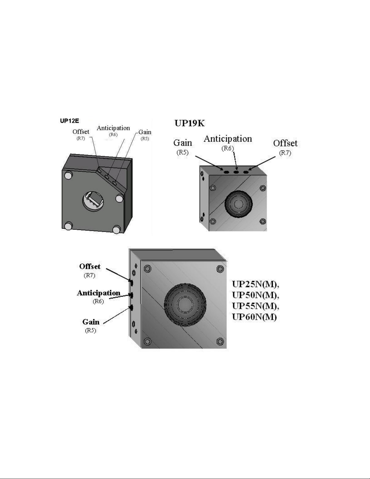
1.5 UP POTENTIOMETER POSITIONS
The UP with amplification has 3 holes on top of the detector for the UP12E, UP19K and the UP25T
and on the left side of the detector for the UP25N(M), UP50N(M), UP55N(M) and the UP60N(M)
giving access to the potentiometers to adjust the gain, the anticipation and the offset, as shown in
figure 1-8.
WARNING : If you are using Gentec-EO calibration, DO NOT change the
potentiometer settings because this would invalidate factory calibration.
FIG. 1-11 POTENTIOMETER POSITIONS
Ultra Series UP Instruction Manual Gentec Electro-Optics Inc. All rights reserved
Page 31

Version 5.0
27
1.6 USING A CUSTOMER-SUPPLIED HEAT SINK
This is a special case. Standard detectors are calibrated and shipped complete with a Gentec-EO
heatsink or back module installed. However, should the customer wish to install an alternative
heatsink or back module, the following indications should be followed. This does not apply to the
XLP, UP_P, UP_T, UP_M, and UP_G series.
Instructions :
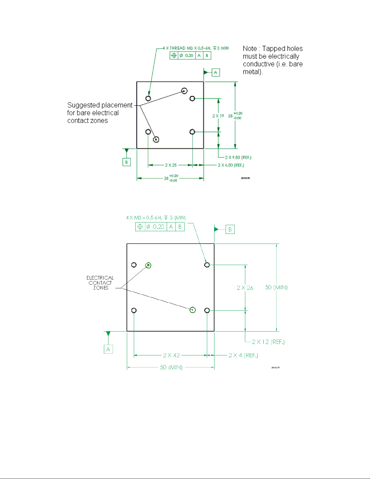
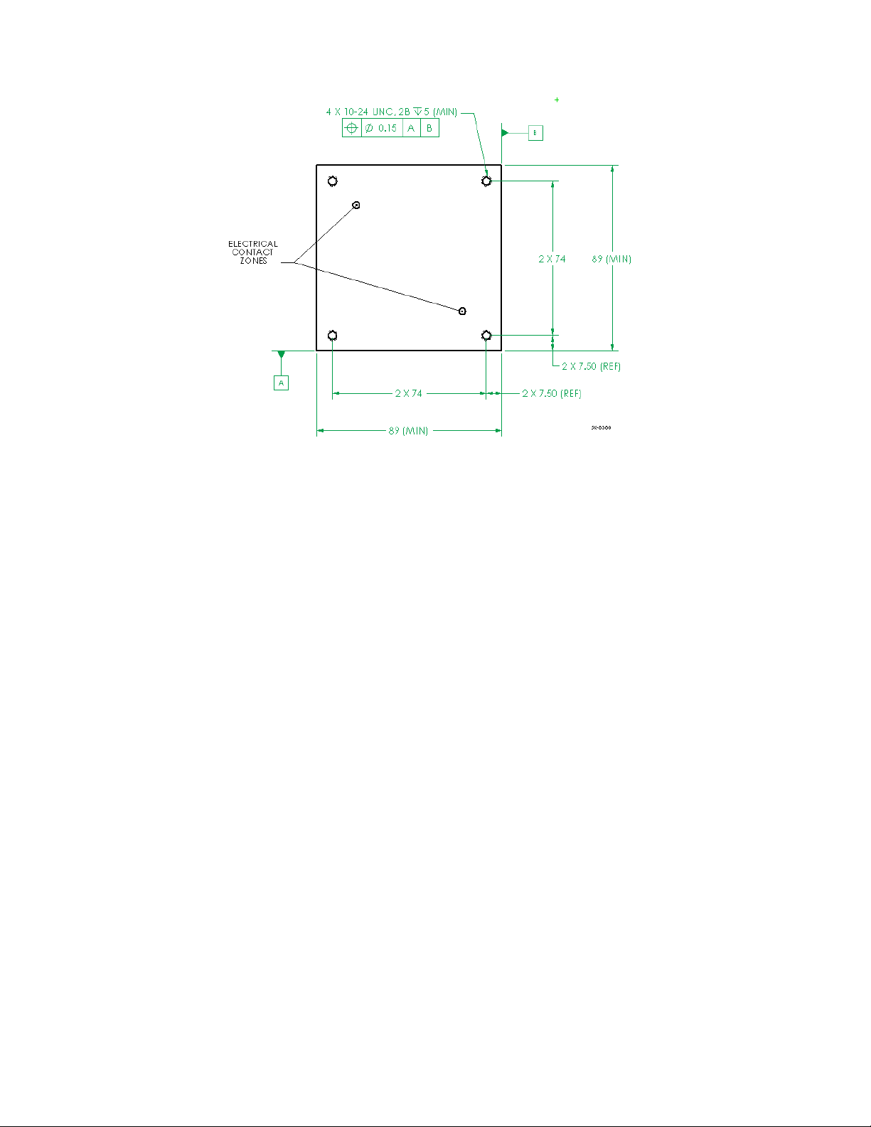
1. Required specifications for customer-supplied back module are given in Fig 1-10 through 1-
12. Note that tapped holes must be electrically conductive, and that there has to be at least
bare spots to allows electrical contact with detector (see point 5.).
2. While keeping together the front cover and the central housing, remove the four front
screws of the UP detector.
3. Discard the back module.
4. Apply electrically-conductive silver epoxy on the bare contact zones of the back module
(Tra-Con, Tra-Duct no. BA-2902). This will ensure proper electrical contact between the
new back module and the central housing.
5. Apply thermal paste (such as Wakefield Engineering Inc. thermal paste part no. 120-2) on
the remainder of back module. This will ensure proper thermal contact with the new back
module.
6. In the case that both central housing and back module are entirely bare and electrically
conducting, a grease that is both thermally and electrically conductive (Timtronics Black Ice
712) may be applied, instead of steps 4. and 5.
7. Install the new back module onto the detector using the the four original screws. It is
strongly advised to apply removable thread locker (Loctite removable thread locker 242) on
the screws before inserting them. The recommended torque for each of the 4 screws is 6
in.lbs. (70 Ncm).
Ultra Series UP Instruction Manual Gentec Electro-Optics Inc. All rights reserved
Page 32
Version 5.0
28
FIG. 1-12 TAPPED HOLE POSITIONS FOR UP12E, WITHOUT PCB
FIG 1-13 TAPPED HOLE POSITIONS FOR UP19K
Ultra Series UP Instruction Manual Gentec Electro-Optics Inc. All rights reserved
Page 33
Version 5.0
29
FIG 1-14 TAPPED HOLE POSITIONS FOR UP25N, UP50N(M), UP55N(M), AND UP60(M)
Ultra Series UP Instruction Manual Gentec Electro-Optics Inc. All rights reserved
Page 34

Version 5.0
30
2 OPERATING INSTRUCTIONS
In order to ensure a long lifetime of accurate measurements, it is recommended that UP wattmeters be
held within the following ambient conditions stated in the specifications.
For a fan-cooled UP, connect the fan to the proper power supply.
NOTE: The UP55G and UP60G must only be used with the Gentec-EO Power Supply
P/N 201103.
For a water-cooled UP, connect the detector head to a an cooling water supply. The water-cooled
UP is equipped with ¼’’ tube fittings .
NOTE: The end of the tube must be cut perpendicular to the tubing; the portion of the
outer tubing wall that slips into the fitting must not be deformed or damaged,
otherwise the connection will not be water-tight.
To connect the detector head fittings to the water supply tubing, unscrew the two parts
of the fitting, push the tubing into the part not connected to the detector until it comes to the end of
the fitting; then screw in the two parts of the fitting.
The direction of flow through the head is unimportant. Once you have connected the fittings, check
them for leaks. If you find a leak, check to see if the tubes are pushed in far enough and that the
tubing has not been damaged.
Verify that the flow rate satisfies the minimum values, as indicated on the specifications pages. A
flow rate of at least 1 l/min is recommend for most models. Time variations of water flow rates or
water temperature may cause corresponding oscillations in measurements.
To disconnect the detector head fittings, remove the water pressure and drain the water from the
tubing. Unscrew the two parts of the fitting and pull out the tubing.
NOTE: Water will usually remain in the detector head after it is disconnected. The
detector should be completely dried out with an air flow before being stored. Be
careful not to blow the water on yourself or on the detector aperture.
Once appropriate cooling is achieved, the UP is ready to be aligned in the intended optical set-up.
1. Remove the power detector cover.
2. Align the detector in the optical set-up, using a safe low-powered beam.
3. For the most accurate measurements, the beam should be centered on the sensor face.
The beam diameter on the sensor should ideally be the same size as the beam diameter of
the original calibration, which corresponds to >98% encircled power centered on 50% of the
sensor’s surface (this complies with the International Electrotechnical Commission standard
#1040: "Power and Energy Measuring Detector..."). Refer to calibration certificate for the
exact calibration beam diameter.
WARNING: Be careful not to exceed the maximum levels and densities stated in
the specifications.
Ultra Series UP Instruction Manual Gentec Electro-Optics Inc. All rights reserved
Page 35

Version 5.0
31
2.1 WITH ANY GENTEC-EO MONITOR
To make a measurement Gentec-EO monitor, continue with the following steps:
4. Connect the detector head to the input socket on the monitor (see the monitor’s instruction
manual).
5. Block off the detector head to prevent it from sensing heat from random sources.
6. Once the reading is thermally stable, the reading should be set to 0 W with the monitor’s
Zero (Offset) function (see the monitor’s instruction manual).
7. Allow the detector head to thermally stabilize before making any subsequent measurement
reading.
2.2 WITHOUT A GENTEC-EO MONITOR
To make a measurement without a Gentec-EO monitor, continue with the following steps:
4. Let the head thermally stabilize for at least 10 minutes, and set up cooling (if fan- or watercooled).
5. Connect the power head to a precision microvoltmeter, or data acquisition system, with a
load impedance that is >100 k (UP without internal circuit board) or with a load impedance
>10 MΩ (UP with internal circuit board). Because of the very low voltages at lower power
levels for some of these detectors, analog or digital filtration may be required to remove
ambient electrical noise.
6. Put the power head into the laser beam path (the laser beam must be contained within the
sensor area) for about one minute.
7. Block off any laser radiation to the detector.
8. Switch on the microvoltmeter and adjust its voltage range to the range required for the range
required for the measurement. To determine the voltage range to be measured, refer to the
detector head specifications:
Vout = (expected power) x (calibration sensitivity of power detector)
9. Wait until the signal has stabilized (fluctuations representing less than 1% of the voltage level
being measured are negligible) then, measure the zero level voltage offset from the
detector. Strong fluctuations in the zero level are usually caused by one of the following:
Rapid fluctuations in the rate of water flow.
Rapid fluctuations in water temperature.
Strong drafts or stray radiation (especially visible when you are
taking low power measurements)
Ambient electrical noise (should be filtered out).
10. Apply the laser beam to the power head.
11. Wait until the signal has stabilized (between one to three minutes for optimum
measurements), then measure the voltage output from the detector (refer to specifications
pages for individual head 0-95% non anticipated response times).
12. The measured power is calculated as follows:
Ultra Series UP Instruction Manual Gentec Electro-Optics Inc. All rights reserved
Page 36

Version 5.0
32
Measured power[W] = (output voltage[V] - zero level voltage[V]) / calibration sensitivity[V/W]
= 1000 x (Vout[mV] - Vzero level[mV]) / calibration sensitivity[mV/W]
2.3 SAFETY OPERATION NOTES
Diffusive surfaces
When using the UP with a coating H, W, and VR be aware of the diffused back reflection:
- H and W: ~ 5-15%
- VR: ~ 40-45%
As on any diffusive surface, the light on the sensor coating is scattered more or less
uniformly as a Lambertian diffuser. It is recommended to use the head with a black
protective sleeve. This will limit wide-angled diffused reflections.
Detector temperature while in operation
During usage, detectors can become hot enough to cause burns.
3 DAMAGE TO THE OPTICAL ABSORBER MATERIAL
Damage to the optical absorber material is usually caused by exceeding the manufacturer's
specifications, such as:
- Incident Average Power Density
- Incident Pulse Energy Density
Refer to the specifications pages for the Ultra Series UP power head specifications. Damage may
also be caused if the absorber surface is contaminated. A slight discoloration of the coating does
not affect the calibration.
In any case, the beam’s incident area should not be less than 10% of the detector’s aperture.
Please contact Gentec-EO to make measurements with such smaller beams.
In the event of significant damage to the coating, the Ultra Series UP sensors can be recoated.
Contact your local Gentec-EO representative for information on repair and recalibration. See p. ii
Contacting Gentec Electro-Optics Inc.
Ultra Series UP Instruction Manual Gentec Electro-Optics Inc. All rights reserved
Page 37

Version 5.0
33
Appendix A: WEEE directive
1.1 Recycling and separation procedure for WEEE directive 2002/96/EC:
This section is used by the recycling center when the detector reaches its end of life.
Breaking the calibration seal or opening the monitor will void the detector warranty.
The complete Detector contains
1 Detector with wires or DB-15.
1 instruction manual
1 calibration certificate
1 Electronic PCB (Integra option)
1 Plastic enclosure (Integra option)
1.2 Separation:
Paper : Manual and certificate
Wires: Cable Detector.
Printed circuit board: inside the Detector (for -MT, -MA, -BT and -CP version only) or DB-15,
no need to separate (less then 10 cm2). Inside the integra enclosure, no need to separate
(less then 10 cm2).
Aluminum: Detector casing.
Plastic: Integra enclosure.
Ultra Series UP Instruction Manual Gentec Electro-Optics Inc. All rights reserved
Page 38
Version 5.0
34
Standard
Description
Performance
Criteria
CISPR11 :2009
+A1 :2010
Industrial, scientific and medical equipment – Radiofrequency disturbance characteristics – Limits and
methods of measurement
Class A
EN 61000-4-2
2009
Electromagnetic compatibility (EMC) – Part 4: Testing
and measurements techniques- Section 4.2:
Electrostatic discharge.
Class B
EN 61000-4-3
2006+A2:2010
Electromagnetic compatibility (EMC) – Part 4: Testing
and measurements techniques- Section 3: Radiated,
Radio Frequency immunity.
Class A
EN 61000-4-4
2004 +A1:2010
Electromagnetic compatibility (EMC) – Part 4: Testing
and measurements techniques- Section 4: Electrical
fast transient/burst immunity.
Class B
EN 61000-4-6
2009
Electromagnetic compatibility (EMC) – Part 4: Testing
and measurements techniques- Section 6: Immunity to
conducted Radio Frequency.
Class A
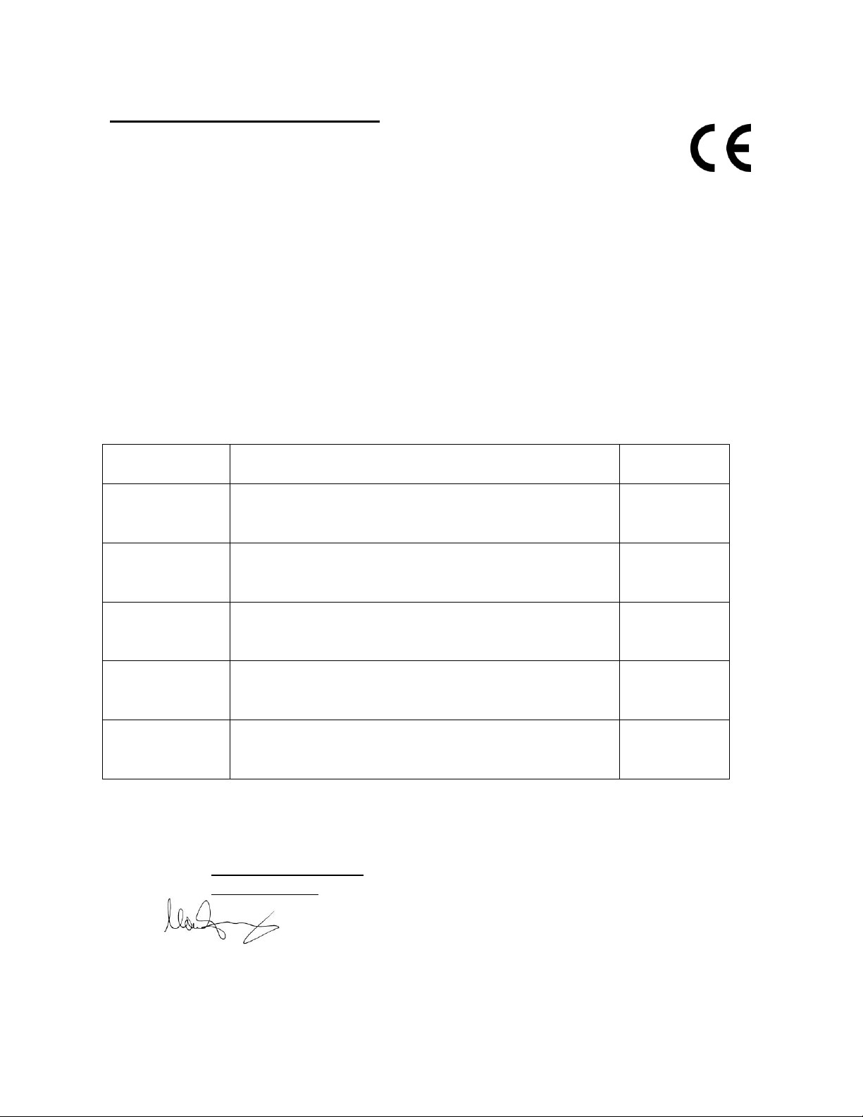
DECLARATION OF CONFORMITY
Application of Council Directive(s): 2004/108/EC EMC Directive
Manufacturer’s Name: Gentec Electro Optics, Inc.
Manufacturer’s Address: 445 St-Jean Baptiste, suite 160
(Québec), Canada G2E 5N7
Representative’s Name: Laser Component S.A.S
Representative’s Address: 45 bis Route des Gardes
92190 Meudon (France)
Type of Equipment: Laser Power/Energy Meter
Model No.: UP&XLP
Year of test & manufacture: 2011
Standard(s) to which Conformity is declared:
EN 61326-1: 2006 Emission generic standard
I, the undersigned, hereby declare that the equipment specified above
conforms to the above Directive(s) and Standard(s)
Place: Quebec (Quebec)
Date : June 18, 2012
(President)
Ultra Series UP Instruction Manual Gentec Electro-Optics Inc. All rights reserved
Page 39
Version 5.0
35
Reading without attenuator
(no units)
Reading with attenuator
f
T
100
(%)
s
f
F
T
XLP12 Filter
Spectral Range
280 nm – 1.36 µm
Typical Transmittance (@ 1.064 µm)
93 %
Typical Reflectance (@ 1.064 µm)
7 %
Dimensions (installed in own mount and
XLP12, ext. x thickness)
1.2 ‘’ x 1/3 ‘’
Appendix B: Using the XLP12 with the XLP12 filter:
The XLP12 filter features ease of installation and removal. To use an XLP12 series wattmeter
(@ any wavelength) with the XLP12 filter, the user must calibrate the assembly using the
following procedure:
Step 1: Set up the XLP12 wattmeter without the filter to measure the power of your laser. Adjust
the sensitivity of the wattmeter to your working wavelength. Verify that the power level is below
the detector’s damage threshold and that the laser has a good stablity.
Step 2: Warm up the detector by applying power to it for a few minutes. This will reduce thermal
bias.
Step 3: Measure the power level (without the filter). To reduce random uncertainty, we
recommend taking the average of 5 distinct measurements.
Step 4: Install the filter. Without changing the laser settings, measure the power level by
averaging the same number of distinct measurements as in Step 3. All laser settings remain
identical as in Step 3, including beam size and position on detector.
Step 5: Repeat the first measurement (Step 3) to verify that there hasn’t been any change
during the procedure that would invalidate the calibration. A difference that is larger than the
uncertainty of your measurement means that something in the laser or environment changed.
You may add this to your uncertainty when using the filter or you may try stabilizing the laser
and environment and repeat from Step 3.
The correction multiplier for the Duo (rev 2.0) and the Solo will be given by:
The correction factor for the Duo (prior to rev 2.0) will be:
Now use calibration factor Fs for the filter when using it at the wavelength established in Step
1.
FIG. 1-15 XLP12 FILTER SPECIFICATIONS
Ultra Series UP Instruction Manual Gentec Electro-Optics Inc. All rights reserved
Page 40
Version 5.0
36
4 tan 5.35a
Appendix C: Using the XLP12 with an optical fiber adaptor:
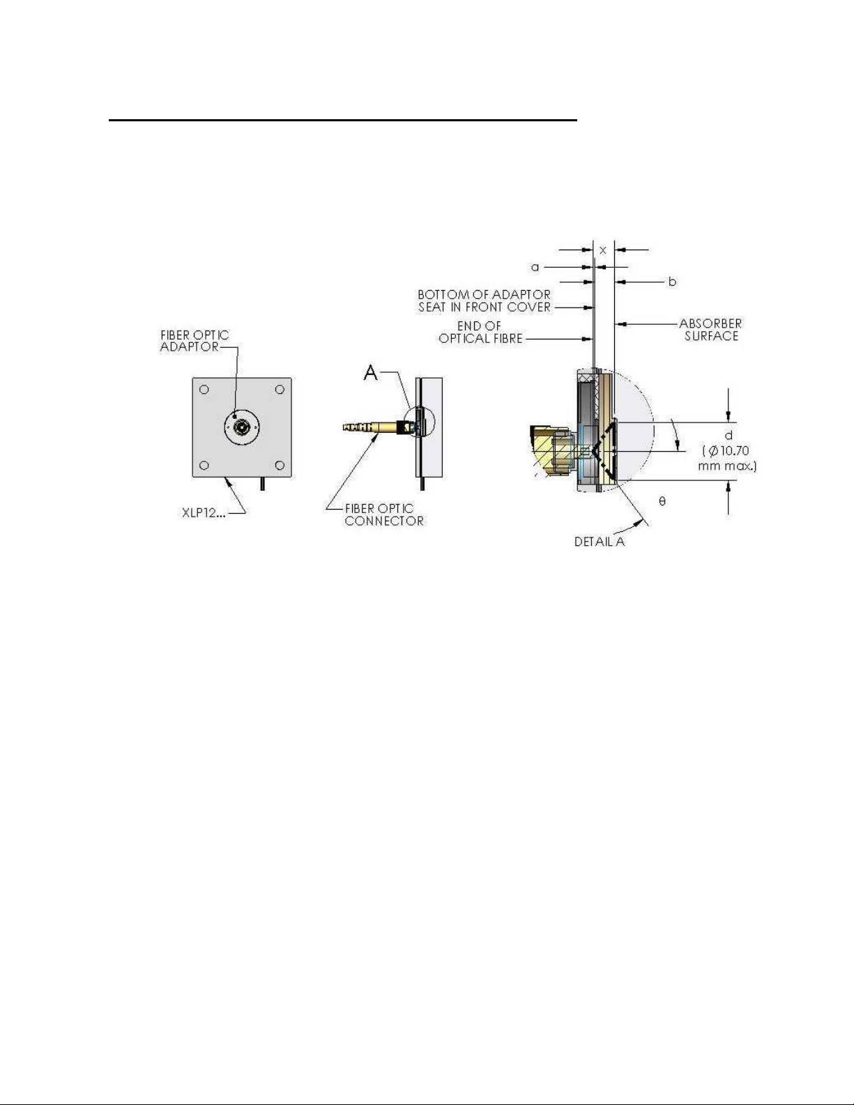
When fitted with an appropriate adaptor, such as Gentec-EO’s FC Optical Fiber Connector, the
XLP12 can be used to measure the output of an optical fiber. When using an optical fiber
adaptor, it is the user's responsibility to ensure that the entire output of the fiber is incident upon
the detector's absorbing surface. Figure 1-10 and the following inequation are provided as a
guide to verify this.
FIG. 1-16 USING AN OPTICAL FIBER ADAPTOR
For the XLP12, the distance in mm between the absorbing surface and the adaptor seat is b =
3.75 ± 0.5. The diameter in mm corresponding to 80% of the absorbing surface (80% is a
common value for allowing sufficient margin to avoid edge effects) is d = 10.7. The acceptance
angle of the fiber is specific to the user’s fiber, as is the value of a, the distance in mm between
the end of the fiber and the interface between the adaptor and its seat on the detector. This
value can be measured once the user’s fiber is connected to the fiber adaptor (a typical value
may be a = 0.2 mm). Once known, the values and a can be entered in the following
inequation:
,
Where, 5.35 is d/2. If the inequation is verified, then it is safe to consider that the light cone,
having a height x = a + b and a maximum diameter d, exiting the fiber is entirely incident on 80%
of the measuring surface of the detector.
Ultra Series UP Instruction Manual Gentec Electro-Optics Inc. All rights reserved
Page 41
 Loading...