

Page 1

Page 2

Version 2.2
Warranty
First Year Warranty
The Gentec-EO thermal power and energy detectors carry a one-year warranty (from date of shipment)
against material and /or workmanship defects when used under normal operating conditions. The
warranty does not cover recalibration, or damages related to misuse.
Gentec-EO will repair or replace at our option any wattmeter or joulemeter which proves to be defective
during the warranty period; except in the case of product misuse.
Any unauthorized alteration or repair of the product is also not covered by the warranty.
The manufacturer is not liable for consequential damages of any kind.
In the case of a malfunction, contact the local Gentec-EO distributor or the nearest Gentec-EO office to
obtain a return authorization number. Return the material to the appropriate address below.
Contacting Gentec Electro-Optics Inc.
To help us answer your calls more efficiently please have the model number of the detector you are
using ready before calling Customer Support.
All customers:
Gentec-EO, Inc.
445 St-Jean-Baptiste, Suite 160
Quebec, QC, G2E 5N7
Canada
Tel: (418) 651-8003
Fax: (418) 651-1174
Email: [email protected]
Web: www.gentec-eo.com
Lifetime Warranty
Gentec-EO will guarantee any thermal power and energy detector head for its lifetime, as long as it has
been returned for recalibration annually, from the shipment date. This warranty includes parts and labor
for all routine repairs including normal wear under normal operating conditions.
Gentec-EO will inspect and repair the detector during the annual recalibration. Repairs at other times will
be at Gentec-EO’s option.
The cost of annual recalibration, or consequential damages from using the detector is not included.
The only condition is that the detector head must not have been subject to unauthorized service or
damaged by misuse. Misuse would include, but is not limited to: laser exposure outside Gentec-EO’s
published specifications, physical damage due to improper handling, and exposure to hostile
environments. Hostile environments would include, but are not limited to: excessive temperature,
vibration, humidity, or surface contaminants; exposure to flame, solvents or water; and connection to
improper electrical voltage.
HP Series Instruction Manual Gentec Electro-Optics Inc. All rights reserved
Page 3

Version 2.2
II
TABLE OF CONTENTS
WARRANTY ................................................................................................................................................... I
TABLE OF CONTENTS ................................................................................................................................ II
LIST OF ILLUSTRATIONS .......................................................................................................................... III
1. HP SERIES POWER DETECTORS .................................................................................................... 1
1.1. INTRODUCTION .............................................................................................................................. 1
1.2. POWER DETECTOR CONNECTORS ............................................................................................ 2
1.2.1. DB-15 “intelligent” connector ....................................................................................................... 2
1.2.2. USB connector ............................................................................................................................. 3
1.2.3. Cooling water ............................................................................................................................... 3
1.3 HP SERIES SPECIFICATIONS .............................................................................................................. 4
2 OPERATING INSTRUCTIONS ............................................................................................................ 6
2.1 WITHOUT A GENTEC-EO MONITOR ................................................................................................. 7
2.2 WITH PC-HP ........................................................................................................................................ 8
2.2.1 PC-HP Warnings ......................................................................................................................... 9
2.2.2 PC-HP Shortcut Buttons ........................................................................................................... 10
2.2.2.1 Zero ....................................................................................................................................... 10
2.2.3 Display menu ............................................................................................................................. 10
2.2.3.1 Display - Histogram ............................................................................................................... 11
2.2.3.2 Display - Tuning Needle ........................................................................................................ 11
2.2.3.3 Display - Status ..................................................................................................................... 12
2.2.3.3.1 Status - Wavelength .......................................................................................................... 12
2.2.3.3.2 Status - Corrections .......................................................................................................... 12
2.2.3.3.3 Status - Anticipation .......................................................................................................... 12
2.2.4 Display - Statistics ..................................................................................................................... 13
2.2.5 Settings menu ............................................................................................................................ 14
2.2.5.1 Data Sampling ....................................................................................................................... 14
2.2.5.2 Settings - Save and Load User Settings ............................................................................... 15
2.2.6 Ctrl menu ................................................................................................................................... 15
2.2.6.1 Ctrl - Communication ............................................................................................................. 16
2.2.6.2 Ctrl - Acquire Data ................................................................................................................. 16
2.2.6.3 Ctrl - Statistics ....................................................................................................................... 16
2.2.7 Help - About ............................................................................................................................... 16
2.2.8 USB driver Installation ............................................................................................................... 16
2.2.9 Verify COM Port ......................................................................................................................... 16
2.2.10 Serial commands ................................................................................................................... 17
3 SAFETY OPERATION NOTES .......................................................................................................... 19
3.1.1 Diffusive surfaces ...................................................................................................................... 19
3.1.2 Detector temperature ................................................................................................................. 19
4 DAMAGE TO THE OPTICAL ABSORBER MATERIAL ..................................................................... 19
5 CE MARK DECLARATION OF CONFORMITY ................................................................................ 21
APPENDIX A: WEEE DIRECTIVE .............................................................................................................. 23
HP Series Instruction Manual Gentec Electro-Optics Inc. All rights reserved
Page 4

Version 2.2
III
LIST OF ILLUSTRATIONS
FIG. 1-1 DB-15 CONNECTOR PIN-OUT ............................................................................................................... 2
FIG. 2-1 PC-HP INTERFACE .................................................................................................................................. 8
FIG. 2-2 A & B PC-HP INTERFACE WARNINGS ................................................................................................ 9
FIG. 2-3 A & B PC-HP INTERFACE WARNINGS ................................................................................................ 9
FIG. 2-4 PC-HP SHORTCUT BUTTONS ............................................................................................................. 10
FIG. 2-5 PC-HP DISPLAY MENU ......................................................................................................................... 10
FIG. 2-6 PC-HP HISTOGRAM ............................................................................................................................... 11
FIG. 2-7 PC-HP TUNING NEEDLE (TWO OPTIONS) ....................................................................................... 11
FIG. 2-8 PC-HP TUNING NEEDLE SETTINGS ................................................................................................... 11
FIG. 2-9 PC-HP SETTINGS WINDOW ................................................................................................................ 12
FIG. 2-10 PC-HP STATISTICS WINDOW ........................................................................................................... 13
FIG. 2-11 PC-HP SETTINGS MENU .................................................................................................................... 14
FIG. 2-12 PC-HP DATA SAMPLING PARAMETER WINDOW. ....................................................................... 14
FIG. 2-13 PC-HP CTRL MENU............................................................................................................................... 15
HP Series Instruction Manual Gentec Electro-Optics Inc. All rights reserved
Page 5

Version 2.2
1
1. HP SERIES POWER DETECTORS
1.1. INTRODUCTION
The Gentec-EO HP Series power detector family includes HP100A-3KW-HE, HP100A-4KW-HE,
HP60A-10KW-GD and HP100A-12KW-HD.
- The HP100A-3KW-HE detector has dimensions of 127 mm x 127 mm and an aperture
of 100 mm.
- The HP100A-4KW-HE detector has dimensions of 127 mm x 127 mm and an aperture
of 100 mm.
- The HP60A-10kW-GD detector has dimensions of 127 mm x 127 mm and an aperture
of 60 mm.
- The HP100A-12KW-HD detector has dimensions of 127 mm x 127 mm and an
aperture of 100 mm.
- The high power surface absorber sensors are designed for use at high average power
densities.
The HP detectors can measure between
- 100 W and 3 KW of average power for HP100A-3KW-HE,
- 100 W and 4 KW of average power for HP100A-4KW-HE,
- 300 W and 10 KW of average power for HP60A-10KW-GD.
- 300 Wand 12 KW of average power for HP100A-12KW-HD.
*For lower power, consult Gentec-eo
The HP-D0 detectors are supplied with a 180 cm length flexible cable with output connection options
of a DB-15 "intelligent" male connector.
NOTE: To eliminate possible damage, do not carry the detector using the connector cable.
Some HP detectors are supplied with a stand (optional).
For cases where Gentec-EO’s monitors don’t automatically read the wavelength correction factor,
you can use your detector’s “Personal wavelength correctionTM Certificate” to adjust the power you
read to a power corrected for a particular wavelength.
Call your nearest Gentec-EO distributor to replace the sensor disk and/or to recalibrate the head.
For Gentec-EO’s nearest office contact information, see p. ii, Contacting Gentec Electro-Optics Inc.
HP Series Instruction Manual Gentec Electro-Optics Inc. All rights reserved
Page 6

Version 2.2
2
1.2. POWER DETECTOR CONNECTORS
1.2.1. DB-15 “intelligent” connector
The DB-15 male "intelligent" connector contains an EEPROM (Electrically Erasable Programmable
Read-Only Memory) with different information related to the HP Series detector head in use: detector
model, calibration sensitivity, applicable scales and wavelength correction factor for up to 20
wavelengths.
This connector, available in the HP, allows the P-LINK, S-Link, SOLO 2, UNO, TUNER, MAESTRO
(detector model, calibration sensitivity, scale and wavelength correction factor) monitors to adjust
their characteristics automatically to the power sensor being connected. No calibration procedure is
required when installing the power heads, allowing for faster set-up.
The DB-15 connector pin-out is composed of (see Fig. 1-1):
1- USED BY MONITOR
2- " " " " "
3- " " " " "
4- " " " " "
5- " " " " "
6- SIGNAL +
7- USED BY MONITOR
8- " " " " "
9- " " " " "
10- " " " " "
11- " " " " "
12- " " " " "
13- SIGNAL -
14- USED BY MONITOR
15- " " " " "
SHELL - BODY GROUND
FIG. 1-1 DB-15 CONNECTOR PIN-OUT
HP Series Instruction Manual Gentec Electro-Optics Inc. All rights reserved
Page 7

Version 2.2
3
1.2.2. USB connector
The USB connector allows using the HP on a PC. The PC interface, PC-HP, features statistical
calculation, graphics displays and data logging options. It also gives real time measurement of
the cooling flow rate and temperature.
A standard USB cable of 5 meters is supplied with the HP. If a longer cable is required, please
contact Gentec-EO for more information.
A USB power adapter (201221) can be ordered with the required AC plug ; USA (201222), UK
(201223), European (201224) and Australian (201225).
1.2.3. Cooling water
The fluid used to cool the HP must be clean water.
Water Fittings and tubing :
- The HP is equipped with 3/8’’ (OD) tube push to connect fittings.
- It must be used with plastic pressure tube systems (like PE tubes).
The fittings is not compatible with copper or stainless steel tubes.
- The metric version of the HP is supplied with an adapter kit (201993) for 10 mm tube (OD).
The kit contains two push to connect 3/8’’ to 10 mm tube adapters and two 3/8’’
coupling tube stems.
The coupling stem is inserted between the HP and the adapter.
Please note that the tube size is written on the adapter output (10 or 3/8).
Water Quality:
- The HP series cooling fluid must be water, do not use glycol or other additive that changes
the coolant’s heat capacity.
- Use filtered (< 10µm) water to avoid any residue.
Gentec-eo can provide an external water filter (202149) if water quality is an issue.
- Distilled water can be used, but it is not recommended to use highly deionized ultra-pure
water because the water cavity is not completely inert.
- If an algaecide must be used in the chiller, we recommended Optishield Plus or equivalent.
- If chloride is present in the system, the concentration should not exceed 25 PPM and the PH
maintained at 7.0.
Water temperature:
- The cooling water can be between 15 and 25°C but must always remains above the dew
point.
- The ideal set point is 20.0°C, where the HP is calibrated.
- Water temperature stability is very important since variations (1 to 60 seconds) in the
temperature can be interpreted as laser power fluctuation.
- Regulate the temperature with a chiller or a re-circulator.
- The water temperature can be monitored with the PC interface PC-HP.
Water Flow rate:
- Flow rate stability is very important since the measured power is directly proportional to the
flow. Variation (1 to 60 seconds) in the flow rate can be interpreted as laser power
fluctuation.
- The flow rate must be adjusted with a valve. A lower flow rate causes a slower response
while increasing the signal to noise ratio. A higher flow rate causes a faster response,
reducing signal to noise ratio.
- The water flow rate can be monitored with the PC interface PC-HP.
Note: All these parameters should remain in the range stated in the specifications.
HP Series Instruction Manual Gentec Electro-Optics Inc. All rights reserved
Page 8

4
HP…
HP100A-3KW-HE
HP100A-4KW-HE
Aperture Diameter
100 mm
Spectral Range
0.19 - 20 µm
Power Noise Level
± 3 W
Typical Rise Time
(0 – 95 %)
7 s
Sensitivity
0.5 mV/W
0.4 mV/W
Calibration Uncertainty
± 5 % @ 1.064 µm
Linearity
with Power
± 1.5 %
± 1.5 %
Repeatability
(Precision)
± 2%
Min. Average Power
(continuous)
100 W
7
100 W
7
Max. Average Power
(continuous)
3 000 W
4 000 W
Max. Average Power
(2 min.)
4 000 W
4500 W
Max. Average Power
Density 12
10 kW/cm² (0.5 kW)
6 kW/cm² (1 kW)
4 kW/cm² (2 kW)
3 kW/cm² (3 kW)
10 kW/cm² (0.5 kW)
8 kW/cm² (1 kW)
6 kW/cm² (2 kW)
4 kW/cm² (4 kW)
Dimension
(mm)
127 (H) x 127 (W) x 74 (D)
Weight
(head only)
1.8 kg
Cooling
Water
Required cooling flow
4 – 6 LPM
< ± 1 LPM/min 3
Temp of cooling water
15 - 25 °C
< ± 3 °C/min 3
Pressure Drop
< 6 psi
< 6 psi
Recommended load
Impedance
> 100 kΩ
Output Impedance
< 675 Ω
Linearity
vs beam dimension
± 1.0 %
Linearity
vs beam position
± 1.5 % 1
PCB electrical supply
USB or
Gentec-EO monitors
Maximum current
consumption
30 mA
Max output signal
2.0 V
1
1.3 HP SERIES SPECIFICATIONS
Version 2.2
For a beam size of 10% of the aperture area, moved across 80% of the aperture area.
HP Series Instruction Manual Gentec Electro-Optics Inc. All rights reserved
Page 9

Version 2.2
HP…
HP60A-10KW-GD
HP100A-12KW-HD
Aperture Diameter
60 mm conical
Optimized for 35 mm
100 mm
Spectral Range
0.8 - 12 µm
0.19 - 20 µm
Power Noise Level
± 10 W
± 10 W
Typical Rise Time
(0 – 95 %)
11 s
9 s
Sensitivity
0.2 mV/W
0.15 mV/W
Calibration Uncertainty
± 5 % @ 1.064 µm
Linearity
with Power
± 2%
Repeatability
(Precision)
± 2%
Min. Average Power
(continuous)
300 W
7
Max. Average Power
(continuous)
10 000 W
12 000 W
Max. Average Power
(5 min.)
10 000 W
12 000 W
Max. Average Power
Density
1 2
< Ø 35 mm: 10 kW/cm² (10 kW)
> Ø 35 mm: 3.5 kW/cm² (10 kW)
16 kW/cm² (0.5 kW)
6.5 kW/cm² (5 kW)
3.5 kW/cm² (10 kW)
Dimension
(mm)
127 (H) x 127 (W) x 90 (D)
127 (H) x 127 (W) x 70 (D)
Weight
(head only)
≈5 kg
3.3 kg
Cooling
Water
Required cooling flow
6 – 10 LPM
< ± 1 LPM/min 3
Temp of cooling water
15 - 25 °C
< ± 3 °C/min 3
Pressure Drop
< 11 psi
Recommended load
Impedance
> 100 kΩ
Output Impedance
< 675 Ω
Linearity
vs beam dimension 4
< Ø 35 mm: ± 0.5 %
> Ø 35 mm: ± 1.5 %
± 1.0 %
Linearity
vs beam position
± 3.0 % 5
± 1.5 % 6
± 3.0 %
5
PCB electrical supply
USB or
Gentec-EO monitors
Maximum current
consumption
30 mA
Max output signal
2.0 V
5
1
: Refer to section 4 for more details on the appropriate beam size in function of measured power.
2
: 1.064, 1.07-1.08 & 10.6 µm.
3
: On a period > 1 minute.
4
: For a centered beam size from 10% to 80% of the aperture area.
5
: For a beam size of 20% of the aperture area, moved across 80% of the aperture area.
6
: For a beam size of 10% of the aperture area, moved across 40% of the aperture area.
7
: For lower power, consult Gentec-eo.
Specifications subject to change without notice.
HP Series Instruction Manual Gentec Electro-Optics Inc. All rights reserved
Page 10

Version 2.2
6
2 OPERATING INSTRUCTIONS
- In order to ensure a long lifetime of accurate measurements, it is recommended that HP is
held within the following ambient conditions:
- Storage environment temperature: 10 to 65°C, RH < 90%
- Operating environment temperature: 15 to 28ºC, RH < 80%.
It is possible to store and operate your Gentec-EO UP wattmeter beyond this range. For any
specific requirement, please contact your local Gentec-EO representative.
- Connect the detecting head (equipped with 3/8’’ tube push to connect fittings) to a water
cooling supply.
NOTE: Ensure that the connection is water-tight by cutting the end of the tube
perpendicular to the tubing. The portion of the outer tubing wall that slips into the fitting must
not be deformed or damaged.
To connect the detector head fittings to the water supply tubing: push the tubing
into the fitting until it comes to the end.
The direction of flow through the head is very important. The measured
power will be negative if the direction is inverted.
Once you have connected the fittings, check them for leaks. If you find a leak,
check to see if the tubes are pushed in far enough and that the tubing has not
been damaged.
To disconnect the detector head fittings, remove the water pressure and drain
the water from the tubing. Press the black part of the fitting and pull out the
tubing.
NOTE: Water will usually remain in the detector head after it is disconnected. It is possible
to remove it by blowing it out, but be careful not to blow the water on yourself or on the
detector aperture. Dry the detector body and absorber off before storing it.
Be sure that flow rates satisfy the minimum values, as indicated on the
specifications page.
Time variations in water flow rates or water temperature will cause
corresponding oscillations in measurements.
The water temperature and flow rate can be monitored with the PC
interface PC-HP.
- For the most accurate measurements, center the beam on the sensor face. The beam
diameter on the sensor should ideally be the same size as the beam diameter of the original
calibration, which corresponds to >98% encircled power centered on 70-90% of the sensor’s
surface (this complies with the International Electrotechnical Commission standard #1040:
"Power and Energy Measuring Detector..."). Refer to the calibration certificate for the exact
calibration beam diameter.
HP Series Instruction Manual Gentec Electro-Optics Inc. All rights reserved
Page 11

Version 2.2
Compatibility
Powered by the monitor
Optional USB
power adapter required
Monitor
Maestro, SOLO 2, UNO, TUNER, P-
LINK USB, S-LINK, TPM-300CE and
S-LINK ETHERNET (if only one HP is
used).
.
SOLO PE, DUO, P-LINK RS232 and,
S-LINK ETHERNET (if more than one
HP is used simultaneously).
7
WARNING:
Be careful not to exceed the maximum levels and densities stated in the
specifications, refer to section 4, Damage to the optical absorber material, for
detailed informations.
Strong fluctuations in the zero level are usually caused by one of the following :
1) Rapid fluctuations in water temperature.
2) Rapid fluctuations in the water flow rate.
WITH ANY GENTEC-EO MONITOR
- To operate the HP detector, connect the detector head to the input socket of the monitor (see
the monitor’s instruction manual).
- If a extension cable is used to connect the HP to a monitor, the HP must be powered from a
PC via the USB port or with an optional USB power adapter.
- Before taking measurements, block off the detector head to prevent it from sensing heat from
random sources. To obtain an accurate reading, the monitors must be zero adjusted.
- Allow the detector head to thermally stabilize before making any measurements. Let the signal
stabilize for a few seconds before adjusting the offset. Refer to the monitor’s operating
instructions for further details.
2.1 WITHOUT A GENTEC-EO MONITOR
- The HP must be powered from a PC via the USB port or with an optional USB power adapter.
- Connect the power head to a precision microvoltmeter, or data acquisition system, with a load
impedance that is >100 k. Because of the very low voltages at lower power levels for some of
these detectors, analog or digital filtration may be required to remove ambient electromagnetic
interference.
- Put the power head into the laser beam path (the laser beam must be contained within the
sensor area) for about a minute.
- Switch on the voltmeter and adjust its voltage range to the range required for the
measurement. To determine the voltage range to be measured, refer to the detector head
specifications:
- Block off any laser radiation to the detector.
- Wait until the signal has stabilized, then measure the zero level voltage offset from the
detector.
- Apply the laser beam to the power head.
- Wait until the signal has stabilized (between one to three minutes for optimum measurements),
then measure the voltage output from the detector .
HP Series Instruction Manual Gentec Electro-Optics Inc. All rights reserved
Vout = (expected power) x (sensitivity of power detector)
Page 12
Version 2.2
8
- The measured power is calculated as follows:
Measured power [W] = (output voltage [V] - zero level voltage [V]) / sensitivity [V/W]
= 1000 x (Vout [mV] - Vzero level [mV]) / sensitivity [mV/W]
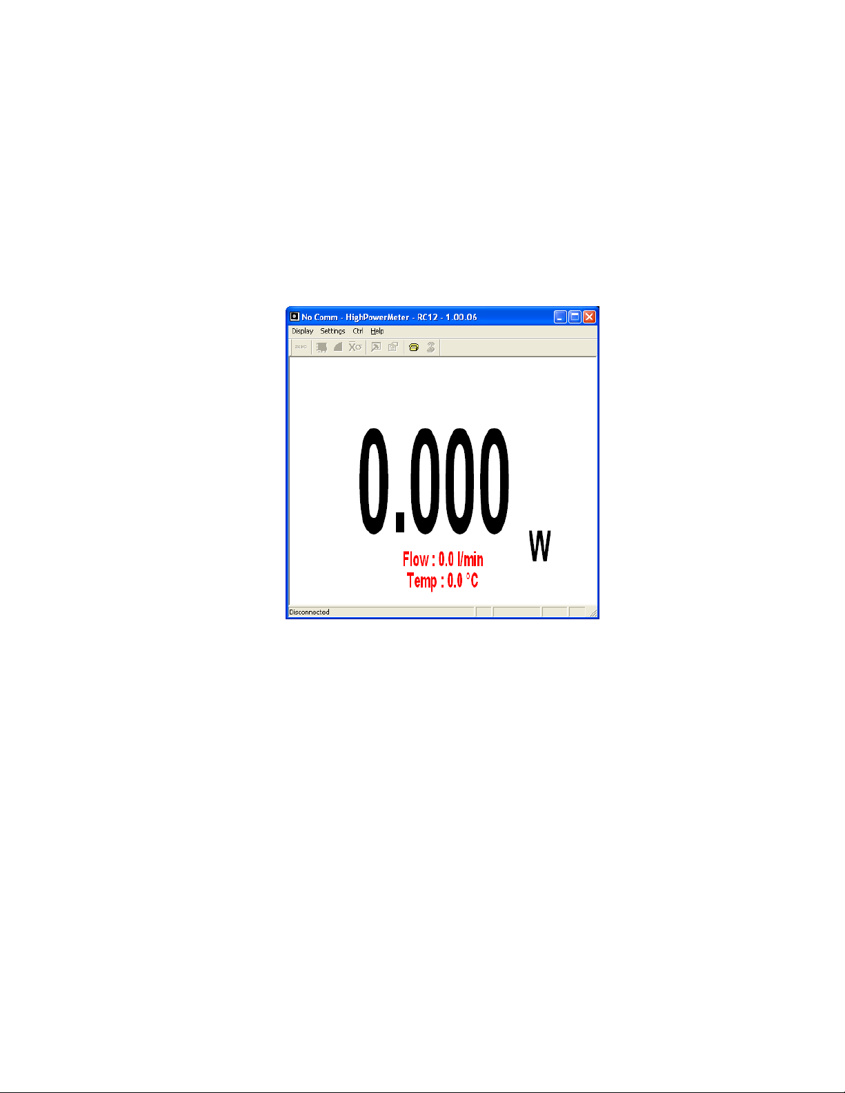
2.2 WITH PC-HP
This section describes in detail the first group of menus essential to the PC-HP operation. The
display menu lets you view the status and your measurement in various ways. Use the settings
menu during setup to set the best parameters for the measurement task at hand. It provides the
flexibility to accommodate a wide variety of measurement conditions.
The water temperature and flow rate are displayed in real-time at the bottom of the interface
.
FIG. 2-1 PC-HP INTERFACE
HP Series Instruction Manual Gentec Electro-Optics Inc. All rights reserved
Page 13
9
2.2.1 PC-HP Warnings
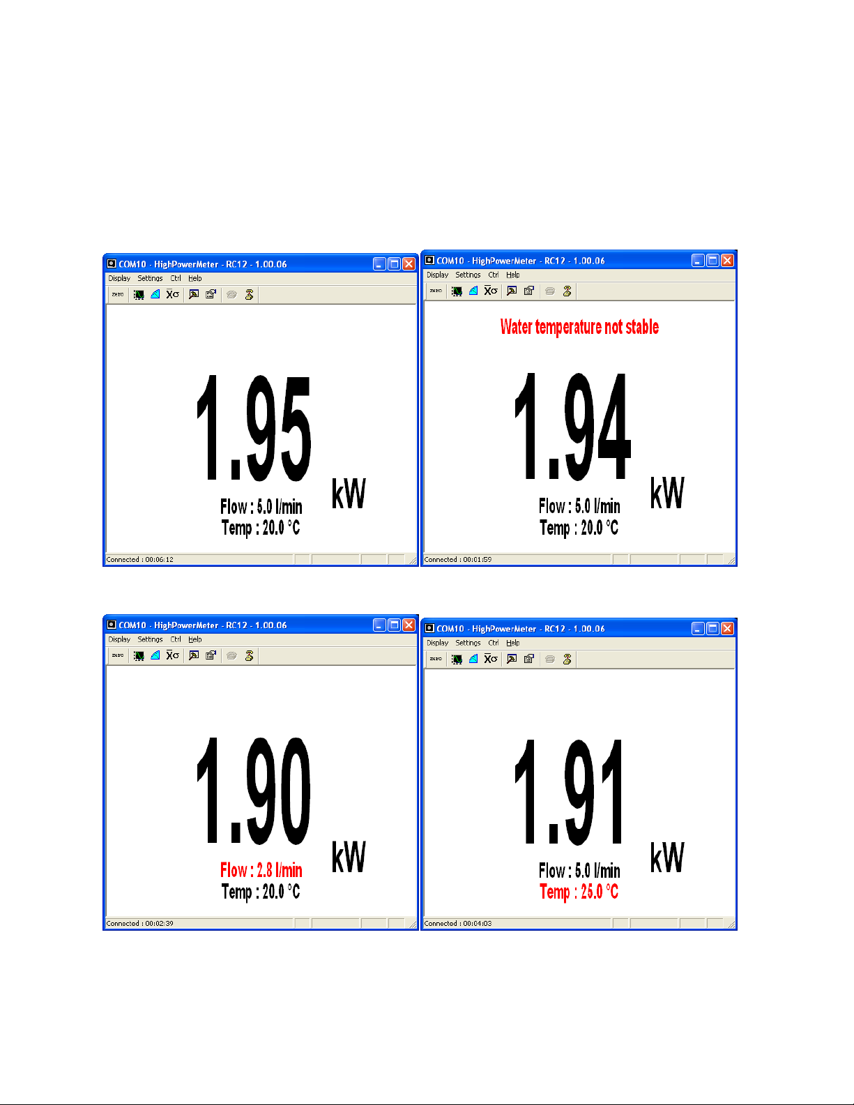
The PC Interface show cooling water status in real time.
The flow rate and temperature are shown in black fonts in normal conditions (FIG 2.2 A).
If the water temperature is not stable a message will appear (FIG 2.2 B).
If the flow rate (FIG 2.3 A) or temperature (FIG 2.3 B) are too high or low the fonts will
change to red as a warning that the measurements will be affected.
Version 2.2
FIG. 2-2 A & B PC-HP INTERFACE WARNINGS
FIG. 2-3 A & B PC-HP INTERFACE WARNINGS
HP Series Instruction Manual Gentec Electro-Optics Inc. All rights reserved
Page 14
10
2.2.2 PC-HP Shortcut Buttons
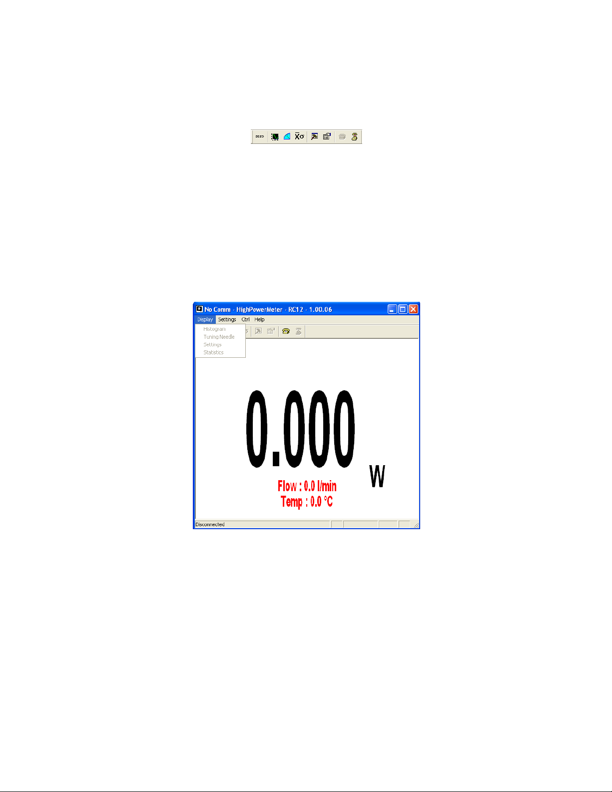
To access certain features with a single click instead of having to enter the menus, PC-HP has 8
shortcut buttons on its main window. From left to right, those buttons access: Zero Offset,
Display - Histogram, Display - Tuning Needle, Display - Statistics, Display - Status, Settings Data Sampling, Ctrl - Communication - Connect, Ctrl - Communication-Disconnect.
FIG. 2-4 PC-HP SHORTCUT BUTTONS
2.2.2.1 Zero
This feature resets the zero reading level to compensate for electronic offsets in the HP and
thermal noise in the environment of the detector. When the HP receives the associated
command, it subtracts the power reading on all its internal hardware scales. Subsequent
measurements will be relative to this zero power level. Use this function once your power meter
has achieved thermal equilibrium to ensure accurate measurements.
For instructions on the proper way to adjust the offset to zero your detector see section 2,
Operatings Instructions.
2.2.3 Display menu
Version 2.2
FIG. 2-5 PC-HP DISPLAY MENU
HP Series Instruction Manual Gentec Electro-Optics Inc. All rights reserved
Page 15
11
2.2.3.1 Display - Histogram
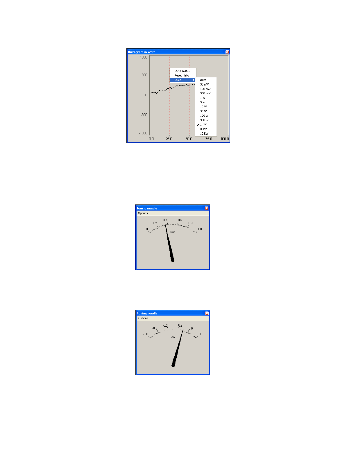
FIG. 2-6 PC-HP HISTOGRAM
Right-click on the histogram to set the time period to view(Set X Axis…), reset the display or
select a scale. Note that the Auto-Scale on the histogram starts from the lowest scale and
only does scale-ups. This is made to select the best scale for the user without frequent scale
oscillations.
2.2.3.2 Display - Tuning Needle
Version 2.2
FIG. 2-7 PC-HP TUNING NEEDLE (TWO OPTIONS)
Right-click on the Tuning Needle to select a scale. The autoscale(default) mode is useful
when the measurement variations are small, because it will zoom on the best possible scale,
but will oscillate with large variations. Use a fixed scale in this case.
FIG. 2-8 PC-HP TUNING NEEDLE SETTINGS
HP Series Instruction Manual Gentec Electro-Optics Inc. All rights reserved
Page 16

12
2.2.3.3 Display - Status
Version 2.2
FIG. 2-9 PC-HP SETTINGS WINDOW
The Settings window displays various settings.
2.2.3.3.1 Status - Wavelength
Use The Wavelength menu to select the power wavelength at which the detector is to be used. It
applies a correction to adjust for the variation in responsivity at different wavelengths. When a
new thermal detector is plugged in, the calibration wavelength is the default selection.
PC-HP only allows you to choose values that fall within the detector’s range. If you select or
enter a value that is not valid, a menu pops up to signal the error and PC-HP automatically
selects the default value. That is the wavelength used for calibration at Gentec-EO during
manufacture or subsequent service.
The HP automatically recognizes every power detector, for accurate auto-calibration. More
importantly, it takes advantage of our Personal wavelength correction™: it reads the memory in
the Smart Interface connector to provide a wavelength correction based on spectral data
measured from that specific detector. Your measurements across the band have never been this
precise and easy.
When working at a wavelength not available in the Wavelength menu, use the custom option. If
you choose custom, a dialog box appears where you can enter a wavelength. The wavelength
you enter must be within the range of valid wavelengths. The HP interpolates a wavelength
correction factor using the pre-programmed data in the detector’s EEPROM.
2.2.3.3.2 Status - Corrections
The user can apply one multiplier and one offset to the detector reading. Correction factors are
most useful when sampling a percentage of a powerful laser beam or correcting for absorption
along an optical chain. The Status window displays the values of correction factors that are being
applied to the measurements. To activate the correction factor, select Status in the Display Menu
and then select Multiplier or Offset. A dialog box opens where you enter the correction value in
percentage or as an absolute value. This number will then multiply, or add to the actual
measured value to calculate the corrected value. PC-HP will then display the corrected value.
Note that the Statistics are computed for the corrected values only.
To disable the correction factor, do a Display – Status – 1 & 0.
2.2.3.3.3 Status - Anticipation
Thermal power detectors are inherently slow. The HP uses an algorithm to significantly
accelerate the response. This is called “anticipation”. By default, this option is enabled. The
reasons for disabling the anticipation are to slow down the response and to lower the noise level.
HP Series Instruction Manual Gentec Electro-Optics Inc. All rights reserved
Page 17
13
Statistical Parameters
Definition
Maximum value
Highest value in the sample period, E
max
or P
max
Minimum value
Lowest value in the sample period, E
min
or P
min
Average value
Rolling average of values in the sample, E
avg
or P
avg
Standard Deviation
A measure of the spread of the data around the average.
RMS stability
Root mean square stability represents the standard deviation as a percent of
the average.
100
avgE
STD
RMS
,
100
avgP
STD
RMS
PTP Stability
Shows the spread between the highest and lowest point in the sample as a
percent.
100
minmax
avg
E
EE
PTP
,
100
minmax
avg
P
PP
PTP
Time
Time elapsed since beginning the sample.
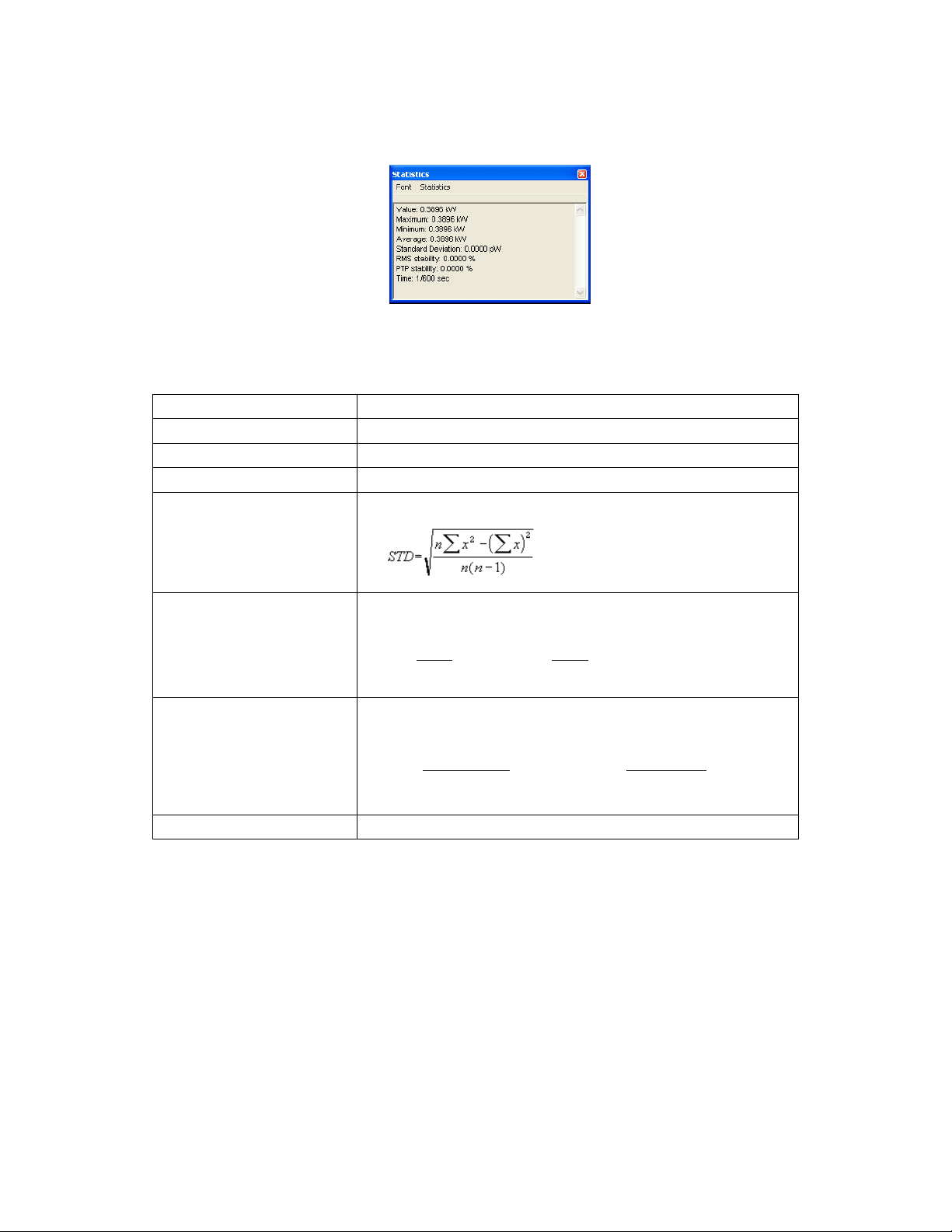
2.2.4 Display - Statistics
The statistics window displays the current statistics. See section 2.2.5.1 to set the data
sampling parameters. See section 2.2.6.3 to learn how to start and stop the statistics.
Version 2.2
FIG. 2-10 PC-HP STATISTICS WINDOW
Table 2.1 Statistical values
HP Series Instruction Manual Gentec Electro-Optics Inc. All rights reserved
Page 18
Version 2.2
14
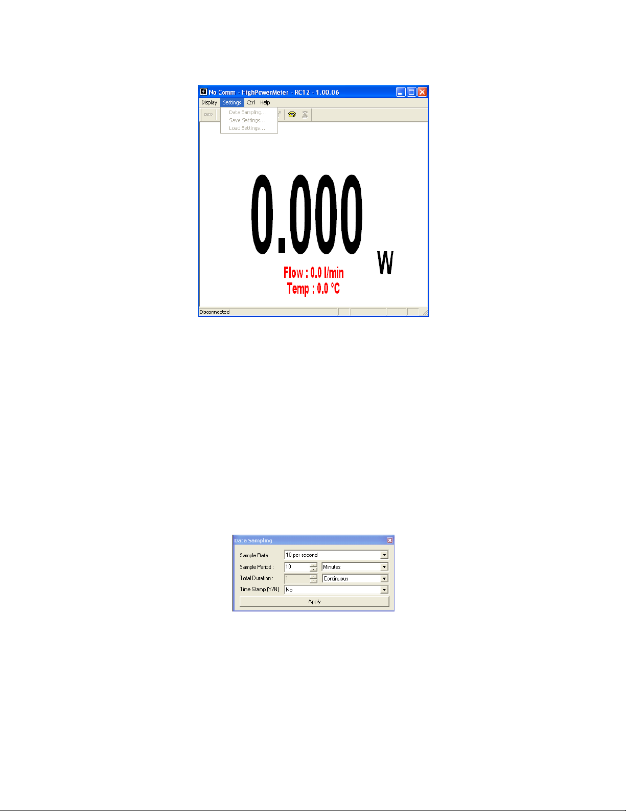
2.2.5 Settings menu
FIG. 2-11 PC-HP SETTINGS MENU
Items in the Settings menu define user-adjustable parameters.
2.2.5.1 Data Sampling
The Data Sampling parameters are used for calculating the statistics(see section 2.2.4) and for
data acquisition(see section 2.2.6.2). PC-HP uses default sampling parameters unless you set
them yourself. You can set PC-HP either to calculate the statistics for a single sample and stop
or to repeat continuously. Take data for a few seconds or a few weeks. You have the flexibility to
handle any application, from analyzing a single short pulse with high resolution to sampling
performance over a period of months.
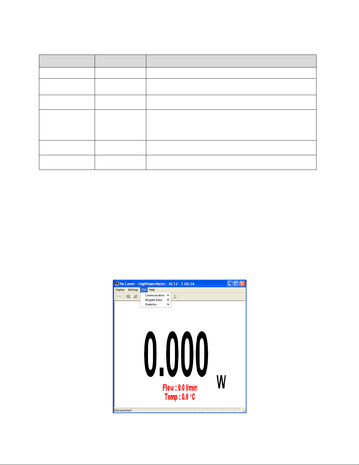
The statistical parameters that are calculated are listed in Table 2.2.
Figure 2.9 shows the window for setting the data sampling parameters. Table 2.2 describes the
parameters. When finished setting them, click save to activate the parameters.
FIG. 2-12 PC-HP DATA SAMPLING PARAMETER WINDOW.
HP Series Instruction Manual Gentec Electro-Optics Inc. All rights reserved
Page 19
Version 2.2
Parameter
Choices
Description
Sample Rate
10Hz to 1 per hour
Sets the number of points (measurements) per second: 10 per second, 1 per
second, 1 per 10 seconds, 1 per minute, 1 per 10 minutes, 1 per hour.
Sample Period
Integer
1 to 1000000000
The time over which samples are to be averaged. Sets the number of samples
used in the average and standard deviation [for example, for each average to
be based on 5 minutes of data, set to 5 minutes..].
Sample period units
Second, Minute
Hour, Day, Week
Sets the time period for the value entered above.
Total Duration
Integer
1 to 1000000000
The time period for which samples are reported (to the display and output).
Select a time period or a number of points [for example, report statistics for 24
hours]. Often the total duration and sample period will be the same.
PC-HP automatically clears and recalculates the statistics at the end of each
sample period unless you manually stop it.
Total Duration units
Continuous
Periods
To make the statistics stop after one sample period, select “1” and “Period.”
Time Stamp
Yes
No
To have a time stamp appear with the acquired data, select “yes” and click
“save”. This is a relative time stamp that always begins at zero.
15
Table 2.2 Data Sampling Parameters
2.2.5.2 Settings - Save and Load User Settings
PC-HP can remember and recall the settings of any number of users. You can share the HP
without the hassle of having to re-enter your settings. As an alternative, you can program it so
that you can easily switch between different measurement applications without having to re-enter
your settings. This option is activated under the Save Settings or Load settings menu items.
When you select settings, a dialog box appears so that you can save your settings to a file. Give
the settings a file name and type. To use established settings, select Load Settings, a dialog
appears. Select the file.
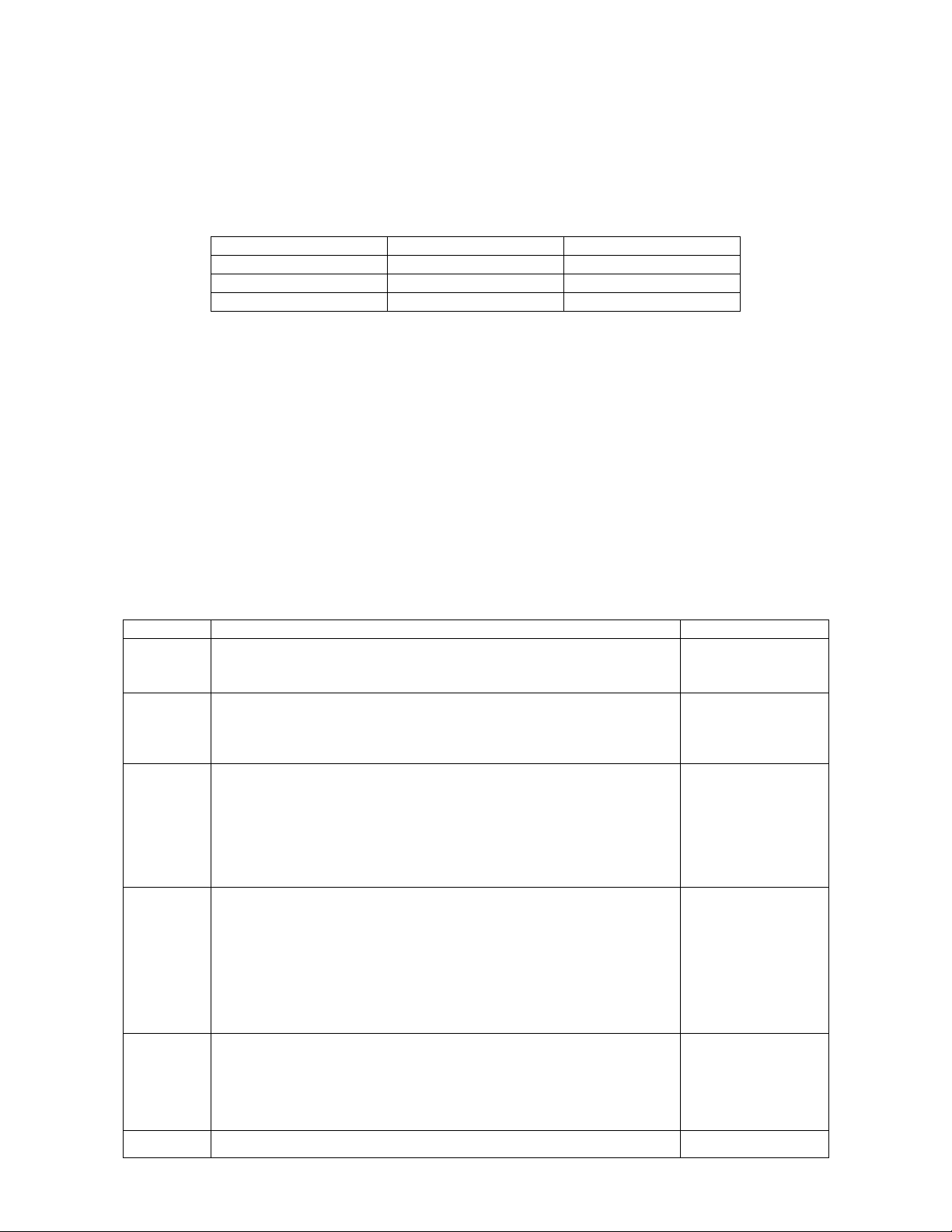
2.2.6 Ctrl menu
This section gives a complete description of the Control menu available on PC-HP.
FIG. 2-13 PC-HP CTRL MENU
HP Series Instruction Manual Gentec Electro-Optics Inc. All rights reserved
Page 20

16
2.2.6.1 Ctrl - Communication
The communication item is mostly used to Connect to the HP after starting PC-HP. To use the
COM port for another application without closing PC-HP, click Ctrl / Communication / Disconnect.
2.2.6.2 Ctrl - Acquire Data
This item is used to save raw data (only), statistics (only), or both raw data and statistics in an
output file. When you select Start Saving Raw Data, a dialog box appears. Type in the filename
that you choose, then select save. PC-HP begins storing raw data according to your Data
Sampling settings (see section 5.2.2). If you will be putting the information into a spreadsheet,
use the Save Both option. All the raw data will be at the top of the file, while all the statistical
information will be at the bottom of each period. The Stop Saving command stops the data
recording but the HP will continue to provide measurements to the display.
2.2.6.3 Ctrl - Statistics
-Select Start to start collecting statistics(when stopped) or to restart them when already in
progress.
-Select Stop to freeze the statistics.
2.2.7 Help - About
This item is helpful to check the software version (About Application…). If you should need help
or additional information on the HP or any Gentec-EO products, do not hesitate to contact us.
We will be glad to help you.
2.2.8 USB driver Installation
Plug the HP into a USB port on the PC. If the PC supports USB 1.1, Windows detects the new
device and prompts you for the software drivers. A window will open that says Found New
Hardware – USB Device and after several seconds to a minute, the Found New Hardware Wizard
will appear.
Insert the GENTEC-EO Software CD-ROM if not done already.
For Windows 2000, XP or Vista: Cancel the wizard and execute the Auto installer “USB driver
installer-r2” in the USB Driver folder from the CD-ROM.
Please note that old monitors without the (R2) at the end of the product name need a different
USB drivers which are available on our web site. They do not support Windows VISTA, unless
noted on the web site.
At the end of this process, a new serial COM port will be added to the list of communication ports.
It may be used as any other serial port. You will need to know the COM port number to set up the
serial connection to the HP.
2.2.9 Verify COM Port
To verify the USB installation and find the COM port number click:
Start → Settings → Control Panel → System → Device Manager
(Instructions may vary a bit by operating system and version. For Win2000/XP there is an
additional step (is there an extra step – if so what is it – or an extra click?- on my system it’s an
extra click) between Control Panel and System.)
Scroll down to Ports (COM & LPT) and double click that line. One of the options should be
USB-to-Serial Port (COM#)
Note the COM port number. You need it for the next step.
Version 2.2
HP Series Instruction Manual Gentec Electro-Optics Inc. All rights reserved
Page 21
Version 2.2
Data
ID
Units
Power
Pw=
Watts
Water Temperature
Tin=
Celsius
Water Flow
F=
Liters per minute
Command
Description
Applies to
*RST
Hardware Reset
The HP will return to default settings.
USB and
DB-15 connector
*VER
Returns information about HP type and firmware version
Example:
HP__A-_KW-H_, Version X.XX.XX
USB only
*F01
Returns information about HP
Serial number, calibration wavelength (nm), DB15 sensitivity
(mV/W)
Example:
SerialNumber: 123456, Lambda : 1064, Sensitivity: 0.X00000
USB only
*F02
Returns information about HP current status
Current wavelength (nm), Thermal offset (W), Offset factor (W),
Multiplication factor and Anticipation status (On/Off).
Example:
Wavelenght: 1064, Thermal Offset : 0, Offset : 0, Multiplier : 1,
Anticipation: On
USB only
*PWC
To set the Wavelength
Wavelength correction command (5+ characters).
Example :
*PWC00808 to selects the wavelength 808 nm
USB only
*OFF
Sets the thermal (zero) offset
USB only
17
2.2.10 Serial commands
The HP Series are automatically sending data through serial port at 9.5 Hz (push mode).
There is no need to ask for readings.
The HP sends the following data:
Example) Pw= 0.0 Ti= 20.000 F= 0.000
HP communication parameters:
a. Bits per second: 57600
b. Data bits : 8
c. Parity: None
d. Stop bits: 1
e. Flow control: None
Serial Commands List:
The star (*) is part of each command and the commands are case sensitive.
HP Series Instruction Manual Gentec Electro-Optics Inc. All rights reserved
Page 22
Version 2.2
See section 2.2.2.1
*MUL
Modifies the multiplication factor (+ 8 characters)
Example :
*MUL1.00E+01 selects a multiplication factor of 10
*MUL10.00000 selects a multiplication factor of 10
USB only
*ADD
Modifies the offset factor (8 characters)
Example :
*OFF2.00E+02 selects a user offset of +200 watts
*OFF-200.000 selects a user offset of -200 watts
USB only
*ANE
Enable the anticipation (default)
See section 2.2.3.3.3
USB and
DB-15 connector
*AND
Disable the Anticipation
See section 2.2.3.3.3
USB and
DB-15 connector
*CVU
Stop the HP to send data automatically (push mode) and
returns a single measurement
Example :
*CVU
Pw= 0.0 Ti= 20.000 F= 0.000
USB only
18
Please note that you must type the exact number of characters or numerical values required and don’t put
any space between characters or numerical values.
HP Series Instruction Manual Gentec Electro-Optics Inc. All rights reserved
Page 23

Version 2.2
Laser
HP100A-3KW-HE
HP100A-4KW-HE
Beam
Damage
Damage 1/e²
Min. 1/e²
Damage
Damage 1/e²
Min. 1/e²
Power
Threshold 2
Beam Diam.
3,4
Beam Diam. 7
,8,5
Threshold 6
Beam Diam.7
,8
Beam Diam.7
,8,
9
[kW]
[kW/cm²]
[cm]
[cm]
[kW/cm²]
[cm]
[cm]
0.5
10
0.4
0.5
10
0.4
0.5 1 6
0.7
0.9
8
0.6
0.8
2 4 1.1
1.6 6 0.9
1.3 3 3
1.6
2.3
5
1.3
1.8
4 4
1.6
2.3
2
3
4
5
19
3 SAFETY OPERATION NOTES
3.1.1 Diffusive surfaces
When using the HP be aware of the diffused back reflection ~ 10-15%.
As on any diffusive surface, the light on the sensor coating is scattered more or less uniformly
as a Lambertian diffuser.
3.1.2 Detector temperature
Detectors can become hot enough during usage to cause burns.
4 DAMAGE TO THE OPTICAL ABSORBER MATERIAL
The HP series are high power meters that can measure up to 12KW. The beam diameter should
always be as large as possible to avoid damage to the absorber. We are recommending between
50% and 80% of the head aperture area, e.g. 7 cm in diameter for the HP100A, 2.5 cm in diameter
for the HP60A-10KW-GD.
The damage threshold is decreasing with the laser beam power. The following table calculates the
diameter corresponding to the damage threshold for a Gaussian beam profile. The “minimum 1/e²
beam diameter” is calculated to obtain a peak intensity 50% lower than the damage threshold and
should be considered as the “safe” minimum diameter. If there are “hot spots” in the beam profile,
they must be considered in the calculation of the peak intensity.
Peak Intensity.
For Gaussian beam profile, the peak intensity is twice the beam power.
Diameter of a circle corresponding to 86% of the entire beam power.
Including a security factor of 50%
HP Series Instruction Manual Gentec Electro-Optics Inc. All rights reserved
Page 24

Version 2.2
Laser
HP60A-10KW-GD (< Ø 35 mm)
HP100A-12KW-HD
HP60A-10KW-GD (> Ø 35 mm)
Beam
Damage
Damage 1/e²
Min. 1/e²
Damage
Damage 1/e²
Min. 1/e²
Power
Threshold 6
Beam Diam.
7,8
Beam Diam. 7
,8,9
Threshold 6
Beam Diam.7
,8
Beam Diam.7
,8,
9
[kW]
[kW/cm²]
[cm]
[cm]
[kW/cm²]
[cm]
[cm]
0.5
40
0.2
0.3
16
0.3
0.4
1
35
0.3
0.4
14
0.4
0.6
2
30
0.4
0.6
12
0.7
0.9
3
25
0.6
0.8
9.7
0.9
1.3
4
20
0.7
1.0
7.9
1.1
1.6
5
17
0.9
1.2
6.5
1.4
2.0
6
15
1.0
1.4
5.6
1.7
2.3
7
13
1.2
1.7
4.9
1.9
2.7
8
12
1.3
1.8
4.3
2.2
3.1
9
11
1.4
2.0
4.0
2.4
3.4
10
10
1.6
2.3
3.5
2.7
3.8
11
3.0
3.1
4.3
12
2.5
3.5
4.9
6
7
8
9
20
In the event of major damage to the coating, the HP Series sensors can be recoated. Contact your
local Gentec-EO representative for information on repair and recalibration. See p. ii Contacting
Gentec Electro-Optics Inc.
Peak Intensity.
For Gaussian beam profile, the peak intensity is twice the beam power.
Diameter of a circle corresponding to 86% of the entire beam power.
Including a security factor of 50%
HP Series Instruction Manual Gentec Electro-Optics Inc. All rights reserved
Page 25
Version 2.2
Standard
Description
Performance
Criteria
EN 61326 :1997
Limits and methods of measurement of radio interference
characteristics of information technology equipment. Testing
and measurements of conducted emission
Class A
EN 61326 : 1997
Limits and methods of measurement of radio interference
characteristics of information technology equipment. Testing
and measurements of radiated emission
Class A
EN 61000-4-2:1995
+A1:1998 A2:2001
Electromagnetic compatibility (EMC) – Part 4: Testing and
measurements techniques- Section 4.2: Electrostatic
discharge.
Class B
EN 61000-4-3:1996
+A1:1998
Electromagnetic compatibility (EMC) – Part 4: Testing and
measurements techniques- Section 3: Radiated, Radio
Frequency immunity.
Class A
ENV 50204: 1995
Radiated Electromagnetic field from digital radio telephonesimmunity test 900MHz pulsed
Class A
EN 61000-4-4:1995
+A1:2001 A2:2001
Electromagnetic compatibility (EMC) – Part 4: Testing and
measurements techniques- Section 4: Electrical fast
transient/burst immunity.
Class B
EN 61000-4-6:1996
+A1:2001
Electromagnetic compatibility (EMC) – Part 4: Testing and
measurements techniques- Section 6: Immunity to conducted
Radio Frequency.
Class A
21
5 CE MARK DECLARATION OF CONFORMITY
Application of Council Directive(s): 2004/108/EC The EMC Directive
Manufacturer’s Name: Gentec Electro Optics, Inc.
Manufacturer’s Address: 445 St-Jean Baptiste, suite 160
(Québec), Canada G2E 5N7
European Representative’s Name: Laser Components S.A.S.
Representative’s Address: 45 bis Route des Gardes
92190 Meudon (France)
Type of Equipment: Laser Power Detector
Model No.: HP Series
Year of test & manufacture: 2008
Standard(s) to which Conformity is declared:
EN 61326: 1997 Emission generic standard
I, the undersigned, hereby declare that the equipment specified above
conforms to the above Directive(s) and Standard(s).
Place: Québec (Québec)
Date : December 1, 2008
______________________
HP Series Instruction Manual Gentec Electro-Optics Inc. All rights reserved
Page 26

22
(President)
Version 2.2
HP Series Instruction Manual Gentec Electro-Optics Inc. All rights reserved
Page 27

Version 2.2
23
Appendix A: WEEE directive
- Recycling and separation procedure for WEEE directive 2002/96/EC:
This section is used by the recycling center when the detector reaches the end of its life.
Breaking the calibration seal or opening the monitor will void the detector warranty.
The complete Detector contains
1 Detector with wires or DB-15.
1 instruction manual
1 calibration certificate
- Separation:
Paper : Manual and certificate
Wires: Cable Detector.
Printed circuit board:
inside the Detector,
DB-15, no need to separate (less then 10 cm2).
Aluminum: Detector casing.
Plastic: parts inside the Detector.
HP Series Instruction Manual Gentec Electro-Optics Inc. All rights reserved
Page 28
 Loading...