

P-LINK User’s Manual Revision 15.0 1
Gentec Electro – Optics, Inc. All rights reserved

P-LINK User’s Manual Revision 15.0 2
WARRANTY
The Gentec-EO P-LINK Single Channel Laser Power/Energy Meter carries a one-year warranty (from
date of shipment) against material and/or workmanship defects, when used under normal operating
conditions. The warranty does not cover damages related to battery leakage or misuse.
Gentec-EO Inc. will repair or replace, optionally, any P-LINK that proves to be defective during the
warranty period, except in the case of product misuse.
Any attempt by an unauthorized person to alter or repair the product voids the warranty.
The manufacturer is not liable for consequential damages of any kind.
In case of malfunction, contact your local Gentec-EO distributor or nearest Gentec-EO Inc. office to obtain
a return authorization number. The material should be returned to:
Gentec Electro-Optics, Inc.
445, St-Jean-Baptiste, Suite 160
Québec, QC
Canada G2E 5N7
Tel: (418) 651-8003
Fax: (418) 651-1174
e-mail: service@gentec-eo.com
Website: www.gentec-eo.com
CLAIMS
To obtain warranty service, contact your nearest Gentec-EO agent or send the product, with a description
of the problem, transportation and insurance prepaid, to the nearest Gentec-EO agent. Gentec-EO Inc.
assumes no risk for the damage in transit. Gentec-EO Inc. will, at its option, repair or replace the
defective product free of charge or refund your purchase price. However, if Gentec-EO Inc. determines
that the failure is caused by misuse, alterations, accident or abnormal condition of operation or handling,
you will be billed for the repair and the repaired product will be returned to you, transportation prepaid.
Gentec Electro – Optics, Inc. All rights reserved

P-LINK User’s Manual Revision 15.0 3
SAFETY INFORMATION
Do not use the P-LINK if the device or the detector looks damaged, or if you suspect that the P-LINK is
not operating properly.
Appropriate installation must be done for water-cooled and fan-cooled detectors. Refer to the specific
instructions for more information. The user must wait for a while before handling these detectors after
power is applied. Surfaces of the detectors get very hot and there is a risk of injury if they are not allowed
to cool down.
Note: This equipment has been tested and found to comply with the limits for a Class B digital
device, pursuant to part 15 of the FCC Rules. These limits are designed to provide
reasonable protection against harmful interference in a residential installation. This
equipment generates, uses, and can radiate radio frequency energy and, if not installed
and used in accordance with the instructions, may cause harmful interference to radio
communications. However, there is no guarantee that interference will not occur in a
particular installation. If this equipment does cause harmful interference to radio or
television reception, which can be determined by turning the equipment off and on, it is
suggested to try to correct the interference by taking one or more of the following steps:
• Reorient or relocate the receiving antenna.
• Increase the distance between the equipment and receiver.
• Connect the equipment to an outlet that is on a different circuit than the receiver.
• Consult the dealer or an experienced radio/TV technician for help.
Caution: Changes or modifications not expressly approved in writing by Gentec-EO Inc. may
void the user’s authority to operate this equipment.
SYMBOLS
The following international symbols are used in this manual:
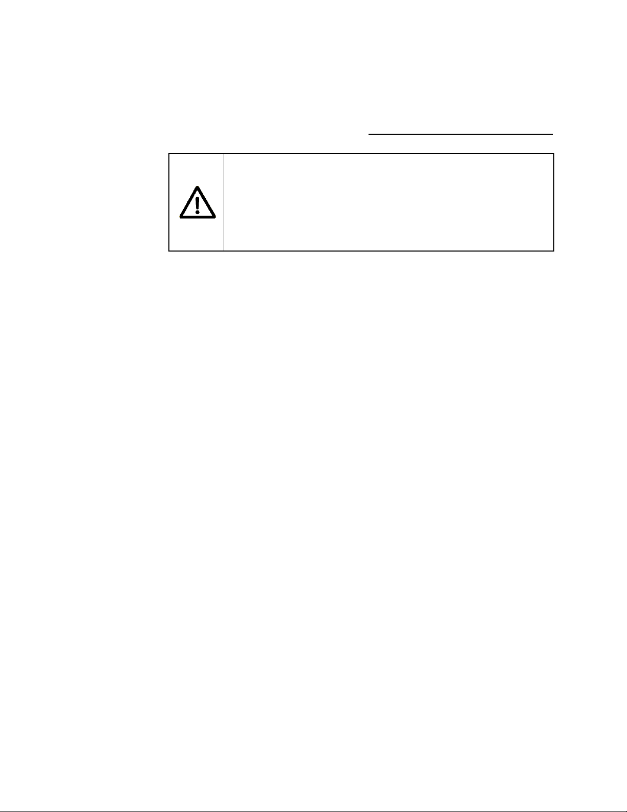
Refer to the manual for specific Warning or Caution information to avoid any damage
to the product.
DC, Direct Current
Gentec Electro – Optics, Inc. All rights reserved

P-LINK User’s Manual Revision 15.0 4
TABLE OF CONTENTS.
P-LINK SINGLE CHANNEL LASER POWER/ENERGY METER
1 INTRODUCTION ................................................................................................................................................... 6
2 SPECIFICATIONS ................................................................................................................................................. 7
3 FRONT PANEL DESCRIPTION : SEE FIGURE 3-1 BELOW........................................................................................ 9
4 GETTING STARTED ........................................................................................................................................... 12
4.1 Quick power measurement procedure ..................................................................................................... 12
5 DESCRIPTION OF THE PC-LINK MENUS ............................................................................................................ 14
5.1 Display menu ........................................................................................................................................... 14
5.1.1 Display - Histogram ......................................................................................................................... 14
5.1.2 Display - Tuning Needle .................................................................................................................. 15
5.1.3 Display - Status ................................................................ ................................................................ 16
5.1.4 Display - Statistics ........................................................................................................................... 16
5.2 Settings menu ........................................................................................................................................... 18
5.2.1 Settings - Wavelength ...................................................................................................................... 18
5.2.2 Settings - Data Sampling ................................................................................................................. 19
5.2.3 Settings - Corrections ....................................................................................................................... 20
5.2.4 Settings - Power Unit ....................................................................................................................... 20
5.2.5 Settings - Energy Mode ................................................................................................................... 20
5.2.6 Settings - Trig Level ........................................................................................................................ 21
5.2.7 Settings - Anticipation ..................................................................................................................... 21
5.2.8 Settings - Attenuator ........................................................................................................................ 22
5.2.9 Settings - Set Max Analog Out Range ............................................................................................. 22
5.2.10 Settings – Analog Out Delay… ....................................................................................................... 22
5.2.11 Settings – Save As Default Layout… .............................................................................................. 22
5.2.12 Settings - Save and Load User Settings ........................................................................................... 22
5.3 Ctrl menu ................................................................................................................................................. 23
5.3.1 Ctrl - Communication ...................................................................................................................... 23
5.3.2 Ctrl - Zero Offset ............................................................................................................................. 23
5.3.3 Ctrl - Acquire Data .......................................................................................................................... 24
5.3.4 Ctrl - Statistics ................................................................................................................................. 24
5.3.5 Ctrl – Send Serial Command ........................................................................................................... 24
5.4 Help - About ................................ ................................ ................................................................ ............. 24
5.5 PC-LINK Shortcut Buttons ..................................................................................................................... 25
6 USB DRIVER INSTALLATION ............................................................................................................................. 26
7 APPENDIX A ..................................................................................................................................................... 27
7.1 P-LINK Serial commands ........................................................................................................................ 27
7.2 P-LINK Error Messages .......................................................................................................................... 29
7.3 Communication Settings ......................................................................................................................... 30
DECLARATION OF CONFORMITY ............................................................................................................................... 31
8 APPENDIX B ..................................................................................................................................................... 32
8.1.1 Recycling and separation procedure ................................................................................................... 32
8.2 Separation ................................................................................................................................................ 32
8.3 Opening the monitor ................................................................................................................................ 33
Gentec Electro – Optics, Inc. All rights reserved

P-LINK User’s Manual Revision 15.0 5
LIST OF ILLUSTRATIONS
TABLE 2-1 LIST OF SPECIFICATIONS ....................................................................................................... 7
FIG. 3-1 P-LINK TOP PANEL .................................................................................................................... 11
FIG. 5-1 PC-LINK DISPLAY MENU ........................................................................................................... 14
FIG. 5-2 PC-LINK HISTOGRAM ................................................................................................................ 14
FIG. 5-3 PC-LINK HISTOGRAM SETTINGS ............................................................................................. 15
FIG. 5-4 PC-LINK TUNING NEEDLE (TWO OPTIONS) ........................................................................... 15
FIG. 5-5 PC-LINK TUNING NEEDLE SETTINGS ..................................................................................... 16
FIG. 5-6 PC-LINK STATUS WINDOW ....................................................................................................... 16
FIG. 5-7 PC-LINK STATISTICS WINDOW ................................................................................................ 17
TABLE 5.8 STATISTICAL VALUES ........................................................................................................... 17
FIG. 5-9 PC-LINK SETTINGS MENU ........................................................................................................ 18
FIG. 5-10 PC-LINK DATA SAMPLING PARAMETER WINDOW. ............................................................. 19
TABLE 5-11 DATA SAMPLING PARAMETERS ....................................................................................... 19
FIG. 5-12 SET MAX ANALOG OUT RANGE DIALOG BOX ...................................................................... 22
FIG. 5-14 PC-LINK HELP MENU ............................................................................................................... 24
FIG. 5-15 PC-LINK SHORTCUT BUTTONS ............................................................................................. 25
Gentec Electro – Optics, Inc. All rights reserved

P-LINK User’s Manual Revision 15.0 6
THE P-LINK SINGLE CHANNEL LASER POWER METER
1 Introduction
To obtain the full performance from the P-LINK, we recommend that you read this manual carefully.
The P-LINK is a microprocessor-based power and energy meter that uses the latest technology to
provide a multitude of options in a user-friendly environment. It is a complete power meter, which can
provide a statistical analysis of your measurements. Moreover, it can be updated over the internet by
connecting the USB or the RS-232 port to a personal computer.
The P-LINK USB version and the RS-232 version have enhanced network capabilities that take further
advantage of the USB or RS-232 ports for data acquisition and remote control depending on the P-LINK
version. It can transfer data files to a PC for more sophisticated data analysis and respond to commands
through the PC interface. Although the default measurement unit is Watt, you may also choose to
measure in dBm.
Easy software upgrade
Keep in touch with the latest improvements to our user-friendly software. You can download the latest
software version anytime from our website www.gentec-eo.com and install it on your PC.
Gentec Electro – Optics, Inc. All rights reserved

P-LINK User’s Manual Revision 15.0 7
Power meter specifications
Power Range
1nW to 10kW
Physical Scale
2V, 15mV
Virtual Power Scales
(photo diode head)
3nW, 10nW, 30nW, 100nW, 300nW, 1µW, 3µW, 10µW, 30µW, 100µW,
300µW, 1mW, 3mW, 10mW, 30mW, 100mW, 300mW, 1W, 3W
Virtual Power Scales
(thermal head)
300 µW, 1 mW, 3 mW, 10 mW, 30mW, 100mW, 300mW, 1W, 3W,
10W, 30W, 100W, 300W, 1kW, 3kW, 10kW
Resolution (digital)
Physical scale/8388608
Monitor Accuracy
± 0.5% 5µV
Response Time
(accelerated)1
1 sec
Sampling Frequency
10Hz
Statistics
Current value, Max, Min, Average, Std Dev., RMS stability, PTP
stability, Time
Energy meter specifications (energy mode)
Energy Range
3mJ to 20kJ
Virtual Energy Scales
3mJ, 10mJ, 30mJ, 100mJ, 300mJ, 1J, 3J, 10J, 30J, 100J, 300J, 1kJ,
3kJ, 10kJ, 30kJ
Resolution (digital)
2nV
Accuracy2
1.0%
Default Trigger Level
250mJ
Software Trigger Level
User defined in Joules
Repetition Frequency
Support all energy mode power heads
Statistics
Current value, Max, Min, Average, Std Dev., RMS stability, PTP
stability, Repetition Rate, Avg Power
General Specifications
Display Rate
3Hz numeric display
10 Hz graphic displays
1
2
2 Specifications
The following specifications are based on a one-year calibration cycle, an operating temperature of 18 to
28ºC (64 to 82ºF) and a relative humidity not exceeding 80%.
Table 2-1 List of Specifications
Varies with detector head.
Including linearity.
Gentec Electro – Optics, Inc. All rights reserved

P-LINK User’s Manual Revision 15.0 8
Data Displays
Real-time, Histogram, Tuning Needle, Statistics,
User input correction
factors
1 multiplier and 1 offset (7 digit floating point)
Analog Output
0 – 2.05 Volt user defined, full scale, ± 1%
Internet Upgrades
USB or RS-232 model
PC Serial Commands
USB or RS-232 model
Dimensions (without
stand)
91 (L) x 57 (W) x 26 max (H) mm
Weight
0.12 kg
External Power Supply for RS-232 version
Universal
Input: 100/240 VAC 50-60 Hz, Output 9-12 VDC 100mA
Gentec Electro – Optics, Inc. All rights reserved
P-LINK User’s Manual Revision 15.0 9
CAUTION
Permanent damage may occur to the optical meter if an external
power supply other than the GENTEC-EO 200130, 200960,
SPU15A-105 or SPU15A-104 is used. Please call GENTEC-EO or
your local distributor if extra power supplies are needed for a
particular setup.
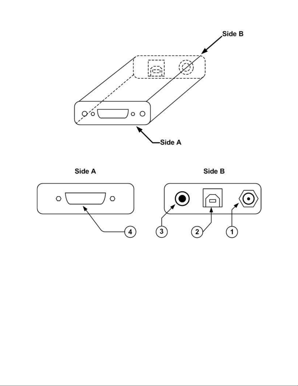
3 Front Panel Description : See figure 3-1 below
1- EXTERNAL POWER SUPPLY INPUT JACK:
Input voltage required: 9-12 VDC/100 mA.
Note: The external power supply input is provided only for the P-LINK with the RS-232
Serial Connection Option.
2- USB INTERFACE CONNECTOR:
This interface allows remote control and data transfers between the P-LINK and a computer
that has a USB communication port. With the RS-232 P-LINK, this connector is use as a RS232 com port.
3- ANALOG OUTPUT:
For monitoring laser average power or energy by using external equipment such as a chart
recorder, a computer with an analog interface, a voltmeter, etc.
The output signal represents a DC analog voltage proportional to the amplified and anticipated
power detector response in the case of a power measurement. In the case of an energy
measurement (energy mode), the output signal is a DC voltage representing the pulse energy
value.
The user must enter the maximum value in the Settings->SET Max Analog Out Range …
menu. This value is the value at which the analog output equal 2.05 V. That provides the
best signal-to-noise ratio. The measured power or energy is then related to the output voltage
and to the selected range according to the following equations:
Vout = Measurement * 2.05 / Max Analog Out Range
For example with a 10W max analog range:
2.05 V corresponds to 10 W
1.025 V corresponds to 5 W
Another useful example: To set the analog output so that 1V corresponds to a measurement
of 56W, the Max Analog Out Range must be set to 20.5 according to the following equation:
Max Analog Out Range = 56 * 2.05
Specifications on the analog output:
Maximum output voltage: 2.05 V
Output impedance: 274
Connector type: Female 1/8” jack
4- PROBE INPUT JACK:
The P-LINK uses a DB-15 female connector to mate with the detector heads (probes).
Gentec Electro – Optics, Inc. All rights reserved

P-LINK User’s Manual Revision 15.0 10
The P-LINK works with all Gentec-EO power detectors. It automatically recognizes every
power detector head, which ensures accurate auto-calibration. More importantly, it can take
advantage of our Personal wavelength correction™. It reads the memory in the Smart
Interface connector (version 5 and higher) to provide a wavelength correction that is based on
spectral data measured from that specific detector.
The P-LINK may not recognize some of the earlier heads.
WARNING: This DB-15 connector, though similar to that of the former TPM-310 and TPM-330
monitors, is incompatible with the power detector heads of PS-310 Series Version 1
and PS-330 Series Version 1. These heads used a different technology and do not
have the same pin-out configuration.
The GENTEC C-300 adaptor can be used in order to connect the power detector heads of PS-
310 Series and PS-330 Series Version 1 and 2. Please contact your local Gentec-EO
distributor or the nearest Gentec-EO office for further information.
Any attempt to modify connectors of the early version heads to mate with the P-LINK can
result in damage to the monitor.
Gentec Electro – Optics, Inc. All rights reserved
P-LINK User’s Manual Revision 15.0 11
Fig. 3-1 P-LINK Top Panel
Gentec Electro – Optics, Inc. All rights reserved
 Loading...