


General Semiconductor BZW04P37, BZW04P342B, BZW04P342, BZW04P33B, BZW04P33 Datasheet
...
BZW04P-5V8 THRU BZW04-376
TRANSZORB™ TRANSIENT VOLTAGE SUPPRESSOR
Stand-off Voltage - 5.8 to 376 Volts Peak Pulse Power - 400 Watts
FEATURES
♦ Plastic package has Underwriters Laboratory
Flammability Classification 94V-0
♦ Glass passivated chip junction
♦ 400W peak pulse power
capability with a 10/1000µs waveform,
repetition rate (duty cycle): 0.01%
♦ Excellent clamping
capability
♦ Low incremental surge resistance
♦ Fast response time: typically less
than 1.0 ps from 0 Volts to V
(BR)
for uni-
directional and 5.0ns for bi-directional types
♦ Typical IDless than 1µA above 10V rating
♦ High temperature soldering guaranteed:
265°C/10 seconds, 0.375" (9.5mm) lead length,
5lbs. (2.3 kg) tension
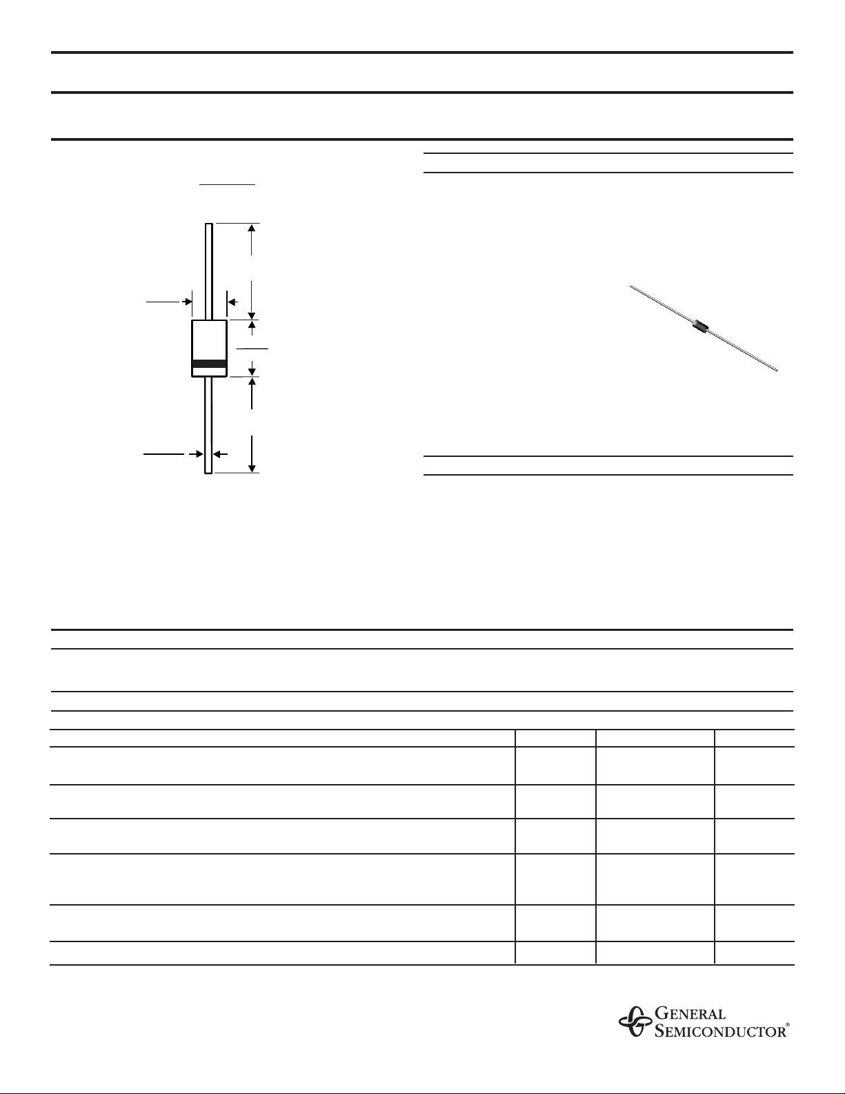
MECHANICAL DATA
Case: JEDEC DO-204AL molded plastic over passivated
junction
Terminals: Plated axial leads, solderable per MIL-STD-750,
Method 2026
Polarity: For unidirectional types the color band denotes
the cathode, which is postitive with respect to the anode
under normal TVS operation
Mounting Position: Any
Weight: 0.012 ounce, 0.3 gram
DEVICES FOR BIDIRECTIONAL APPLICATIONS
For bi-directional use add suffix Letter "B" (e.g. BZW04P-6V4B).
Electrical characteristics apply in both directions.
MAXIMUM RATINGS AND CHARACTERISTICS
Ratings at 25°C ambient temperature unless otherwise specified.
SYMBOL VALUE UNITS
Peak pulse power dissipation with a 10/1000µs waveform
(NOTE 1, FIG. 1)
P
PPM
Minimum 400 Watts
Peak pulse current with a 10/1000µs waveform
(NOTE 1)
I
PPM SEE TABLE 1
Amps
Steady state power dissipation at T
L
=75°C
lead lengths, 0.375” (9.5mm)
(NOTE 2)
P
M(AV)
1.0 Watts
Peak forward surge current, 8.3ms single half
Sine-wave superimposed on rated load
(JEDEC Method)
(NOTE 3)
unidirectional only
I
FSM
40.0 Amps
Maximum instantaneous forward voltage at 25A
(NOTE 4)
uni-directional only
V
F
3.5/5.0 Volts
Operating junction and storage temperature range T
J
, T
STG
-55 to +175 °C
NOTES:
(1) Non-repetitive current pulse, per Fig. 3 and derated above T
A
=25°C per Fig. 2
(2) Mounted on copper pad area of 1.6 x 1.6” (40 x 40mm) per Fig. 5
(3) 8.3ms single half sine-wave or equivalent square wave, duty cycle=4 pulses per minute maximum
(4) V
F
=3.5V max. for devices of V
(BR)
≤220V and VF=5.0 Volt max. for devices of V
(BR)
>220V
1/5/98
DO204AL
0.107 (2.7)
0.080 (2.0)
0.034 (0.86)
0.028 (0.71)
DIA.
1.0 (25.4)
MIN.
1.0 (25.4)
MIN.
0.205 (5.2)
0.160 (4.1)
DIA.
NOTE:
Lead diameter is for suffix "E" part numbers
0.026 (0.66)
0.023 (0.58)
Dimensions are in inches
and
(millimeters)

ELECTRICAL CHARACTERISTICS at (T
A
=25°C unless otherwise noted) TABLE 1
Maximum
Breakdown Voltage Maximum Peak Pulse Maximum Maximum
V
(BR)
Stand-off Reverse Current Clamping Temperature
Volts
(NOTE 1)
Test Voltage Leakage I
PPM
Voltage at Coefficient
Current V
WM
at V
WM
(Amps) I
PPM
of V
(BR)
Device Type MIN MAX
at I
T
(Volts) ID (µA)
(NOTE 2)
VC (Volts) (% / C)
(mA)
(NOTE4)
BZW04P5V8 6.45 7.48 10.0 5.80 1000 38.0 10.5 0.057
BZW04-5V8 6.45 7.14 10.0 5.80 1000 38.0 10.5 0.057
BZW04P6V4 7.13 8.25 10.0 6.40 500 35.4 11.3 0.061
BZW04-6V4 7.13 7.88 10.0 6.40 500 35.4 11.3 0.061
BZW04P7V0 7.79 9.02 10.0 7.02 200 33.0 12.1 0.065
BZW04-7V0 7.79 8.61 10.0 7.02 200 33.0 12.1 0.065
BZW04P7V8 8.65 10.0 1.0 7.78 50.0 30.0 13.4 0.068
BZW04-7V8 8.65 9.55 1.0 7.78 50.0 30.0 13.4 0.073
BZW04P8V5 9.50 11.0 1.0 8.55 10.0 27.6 14.5 0.073
BZW04-8V5 9.50 10.5 1.0 8.55 10.0 27.6 14.5 0.075
BZW04P9V4 10.5 12.1 1.0 9.4 5.0 25.7 15.6 0.075
BZW04-9V4 10.5 11.6 1.0 9.4 5.0 25.7 15.6 0.075
BZW0P10 11.4 13.2 1.0 10.2 5.0 24.0 16.7 0.078
BZW04-10 11.4 12.6 1.0 10.2 5.0 24.0 16.7 0.078
BZW04P11 12.4 14.3 1.0 11.1 5.0 22.0 18.2 0.081
BZW04-11 12.4 13.7 1.0 11.1 5.0 22.0 18.2 0.081
BZW04P13 14.3 16.5 1.0 12.8 5.0 19.0 21.2 0.084
BZW04-13 14.3 15.8 1.0 12.8 5.0 19.0 21.2 0.084
BZW04P14 15.2 17.6 1.0 13.6 5.0 17.8 22.5 0.086
BZW04-14 15.2 16.8 1.0 13.6 5.0 17.8 22.5 0.086
BZW04P15 17.1 19.8 1.0 15.3 5.0 16.0 25.2 0.088
BZW04-15 17.1 18.9 1.0 15.3 5.0 16.0 25.2 0.088
BZW04P17 19.0 22.0 1.0 17.1 5.0 14.5 27.7 0.090
BZW04-17 19.0 21.0 1.0 17.1 5.0 14.5 27.7 0.090
BZW04P19 20.9 24.2 1.0 18.8 5.0 13.0 30.6 0.092
BZW04-19 20.9 23.1 1.0 18.8 5.0 13.0 30.6 0.092
BZW04P20 22.8 26.4 1.0 20.5 5.0 12.0 33.2 0.094
BZW04-20 22.8 25.2 1.0 20.5 5.0 12.0 33.2 0.094
BZW04P23 25.7 29.7 1.0 23.1 5.0 10.7 37.5 0.096
BZW04-23 25.7 28.4 1.0 23.1 5.0 10.7 37.5 0.096
BZW04P26 28.5 33.0 1.0 25.6 5.0 9.6 41.5 0.097
BZW04-26 28.5 31.5 1.0 25.6 5.0 9.6 41.5 0.097
BZW04P28 31.4 36.3 1.0 28.2 5.0 8.8 45.7 0.098
BZW04-28 31.4 34.7 1.0 28.2 5.0 8.8 45.7 0.098
BZW04P31 34.2 39.6 1.0 30.8 5.0 8.0 49.9 0.099
BZW04-31 34.2 37.8 1.0 30.8 5.0 8.0 49.9 0.099
BZW04P33 37.1 42.9 1.0 33.3 5.0 7.4 53.9 0.100
BZW04-33 37.1 41.0 1.0 33.3 5.0 7.4 53.9 0.100
BZW04P37 40.9 47.3 1.0 36.8 5.0 6.7 59.3 0.101
BZW04-37 40.9 45.2 1.0 36.8 5.0 6.7 59.3 0.101
BZW04P40 44.7 51.7 1.0 40.2 5.0 6.2 64.8 0.101
BZW04-40 44.7 49.4 1.0 40.2 5.0 6.2 64.8 0.101
BZW04P44 48.5 56.1 1.0 43.6 5.0 5.7 70.1 0.102
BZW04-44 48.5 53.6 1.0 43.6 5.0 5.7 70.1 0.102
BZW04P48 53.2 61.6 1.0 47.8 5.0 5.2 77.0 0.103
BZW04-48 53.2 58.8 1.0 47.8 5.0 5.2 77.0 0.103
 Loading...