

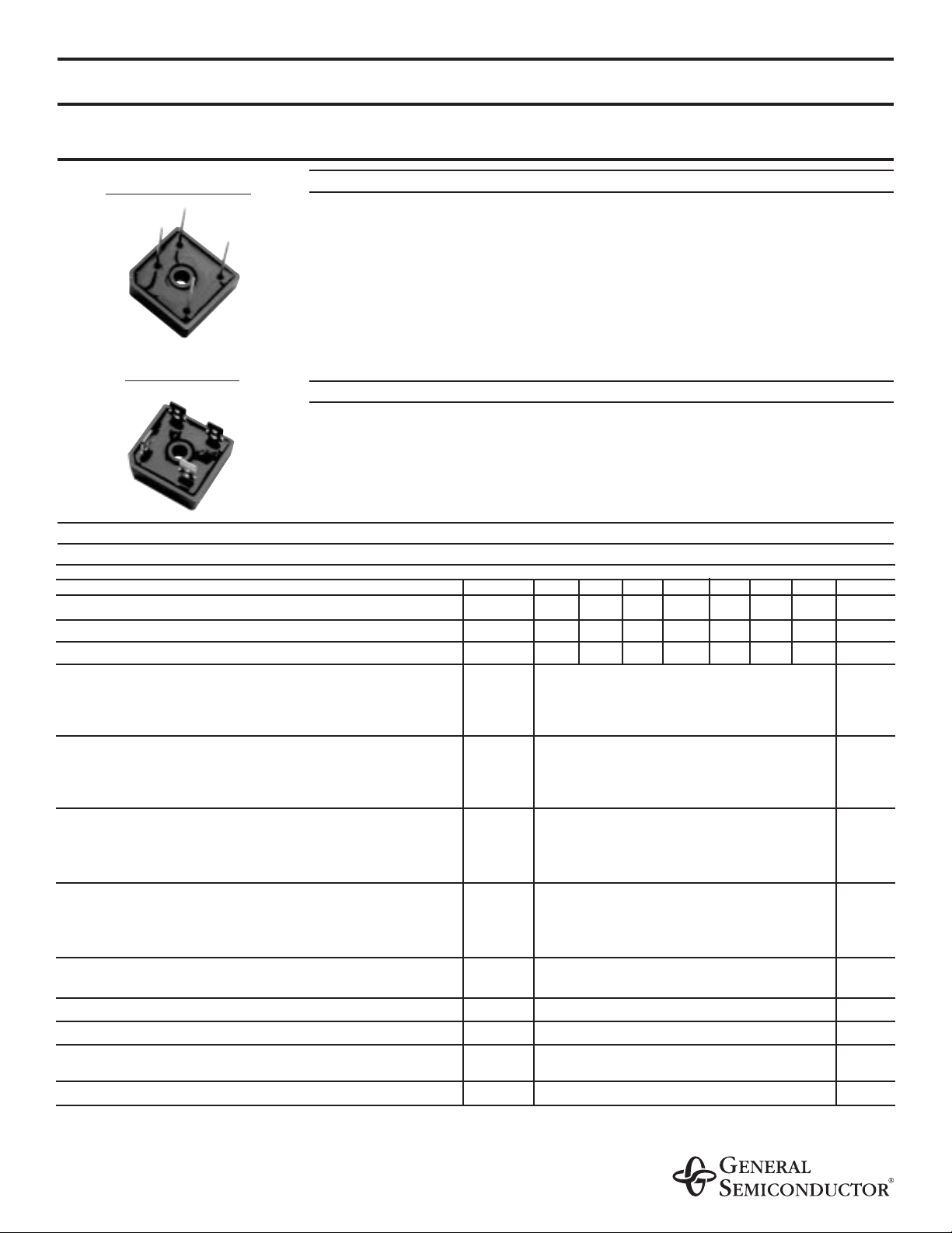
GBPC12, 15, 25 AND 35 SERIES
GLASS PASSIVATED SINGLE-PHASE BRIDGE RECTIFIER
Reverse Voltage - 50 to 1000 Volts Current Voltage - 12.0 to 35.0 Amperes
FEATURES
♦ The plastic package has Underwriters Laboratory Flammability Classification 94V-0
♦ This series is UL recognized under component index, file number E54214
♦ Integrally molded heatsink provides very low thermal resistance for maximum heat
dissipation
♦ Universal 3-way terminals; snap-on, wire wrap-around, or P.C.B. mounting
♦ High forward surge current capabilities
♦ Glass passivated chip junctions
♦ Typical IRless than 0.3µA
♦ High temperature soldering guaranteed:
260°C/10 seconds at 5lbs. (2.3 kg) tension
MECHANICAL DATA
Case: Molded plastic with heatsink integrally mounted in the bridge encapsulation
Terminals: Either plated 0.25" (6.35mm). Faston lugs or plated copper leads 0.040"
(1.02mm) diameter. Suffix letter "W" added to indicate leads (e.g. GBPC12005W).
Mounting Position: See
NOTE 3
Polarity: Polarity symbols molded on body
Mounting Torque: 20 in. - lb. max. Weight: 0.53 ounce, 15 grams
MAXIMUM RATINGS AND ELECTRICAL CHARACTERISTICS
Ratings at 25°C ambient temperature unless otherwise specified.
GBPC12, 15, 25, 35
SYMBOLS 005 01 02 04 06 08 10 UNITS
Maximum repetitive peak reverse voltage V
RRM
50 100 200 400 600 800 1000 Volts
Maximum RMS voltage V
RMS
35 70 140 280 420 560 700 Volts
Maximum DC blocking voltage V
DC
50 100 200 400 600 800 1000 Volts
Maximum average forward GBPC12 12.0
rectified output current GBPC15
I
(AV)
15.0
Amps
(SEE FIG.1)
GBPC25 25.0
GBPC35 35.0
Peak forward surge current single GBPC12 200.0
sine-wave superimposed on GBPC15 I
FSM
300.0 Amps
rated load (JEDEC Method) GBPC25 300.0
GBPC35 400.0
Rating (non-repetitive, for t GBPC12 160.0
greater than 1ms and less GBPC15
I
2
t
375.0
A2 sec
than 8.3ms) for fusing GBPC25 375.0
GBPC35 660.0
Maximum instantaneous GBPC12 I
F
=6.0A
forward voltage drop per GBPC15 I
F
=7.5A
V
F
1.1 Volts
leg at GBPC25 I
F
=12.5A
GBPC35 I
F
=17.5A
Maximum reverse DC current at rated T
A
=25°C 5.0
DC blocking voltage per leg T
A
=125°C
I
R
500.0
µA
RMS isolation voltage from case to leads V
ISO
2500.0 Volts
Typical junction capacitance per leg
(NOTE 1)
C
J
300.0 pF
Typical thermal resistance per leg
(NOTE 2)
GBPC12-25
R
ΘJC
1.9
°C/W
GBPC35 1.4
Operating junction storage temperature range T
J
, T
STG
-55 to +150 °C
NOTES:
(1) Measured at 1.0 MHz and applied reverse voltage of 4.0 Volts
(2) Thermal resistance from junction to case per leg
(3) Bolt down on heat-sink with silicone thermal compound between bridge
and mounting surface for maximum heat transfer efficiency with #10 screw
GBPC - W Wire leads
GBPC - Standard
7/28/98
RATINGS AND CHARACTERISTICS CURVES GBPC12, 15, 25 AND 35 SERIES
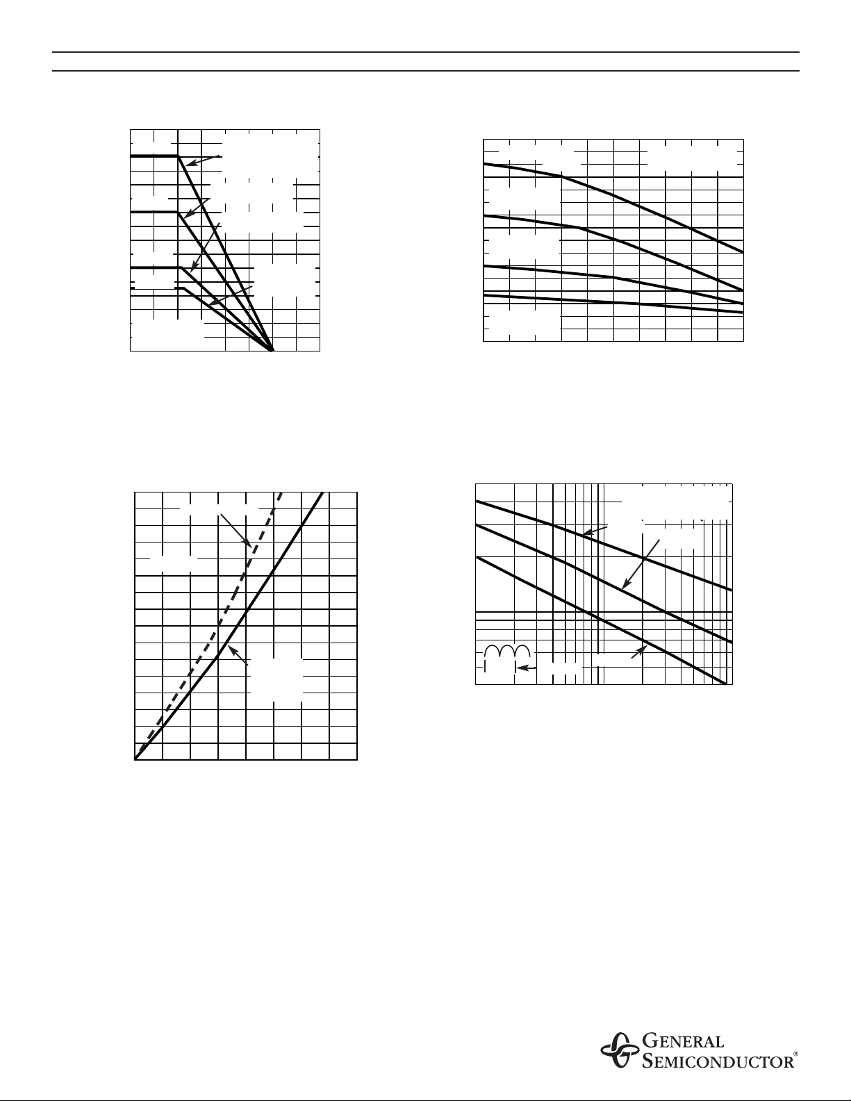
FIG. 1 - MAXIMUM OUTPUT RECTIFIED CURRENT
CASE TEMPERATURE, °C
5 x 6 x 4.9”
AL. FINNED PLATE
AVERAGE POWER DISSIPATION OF BRIDGE,
WATTS
FIG. 3 - MAXIMUM POWER DISSIPATION
TJ=TJmax.
BRIDGES MOUNTED
on 9 x 3.5 x 4.6”
(22.9 x 8.9 x 11.7cm)
AL. FINNED PLATE
AVERAGE FORWARD CURRENT,
AMPERES
FIG. 2 - MAXIMUM OUTPUT RECTIFIED CURRENT
CAPACITIVE LOAD
60 Hz RESISTIVE
OR INDUCTIVE
LOAD
5 x 4 x 3”
AL. FINNED PLATE
6.0 x 2.2 x 2.2”
AL. FINNED
PLATE
GBPC12
GBPC15
GBPC25
AVERAGE FORWARD CURRENT,
AMPERES
AMBIENT TEMPERATURE, °C
60 HZRESISTIVE OR
INDUCTIVE LOAD
GBPC25
RthS-A=0.5 °C/W
GBPC15
RthS-A=1.0 °C/W
GBPC12
RthS-A=1.0 °C/W
RthS-A=0.5 °C/W
RESISTIVE
OR
INDUCTIVE
LOAD
AVERAGE OUTPUT CURRENT, AMPERES
GBPC35
GBPC35
PEAK FORWARD SURGE CURRENT,
AMPERES
FIG. 4 - MAXIMUM NON-REPETITIVE PEAK FORWARD
SURGE CURRENT PER LEG
GBPC12
GBPC15
GBPC25
GBPC35
NUMBER OF CYCLES AT 60Hz
TJ=TJmax.
0.5Single Sine-Wave
(JEDEC Method)
1.0 CYCLE
40
35
30
25
20
15
10
5
0
0 25 50 75 100 125 150 175 200
40
35
30
25
20
15
10
5
0
0 102030405060708090100
80
70
60
50
40
30
20
10
0
0
10
20
30
40
500
100
1
10
100
RATINGS AND CHARACTERISTICS CURVES GBPC12, 15, 25 AND 35 SERIES
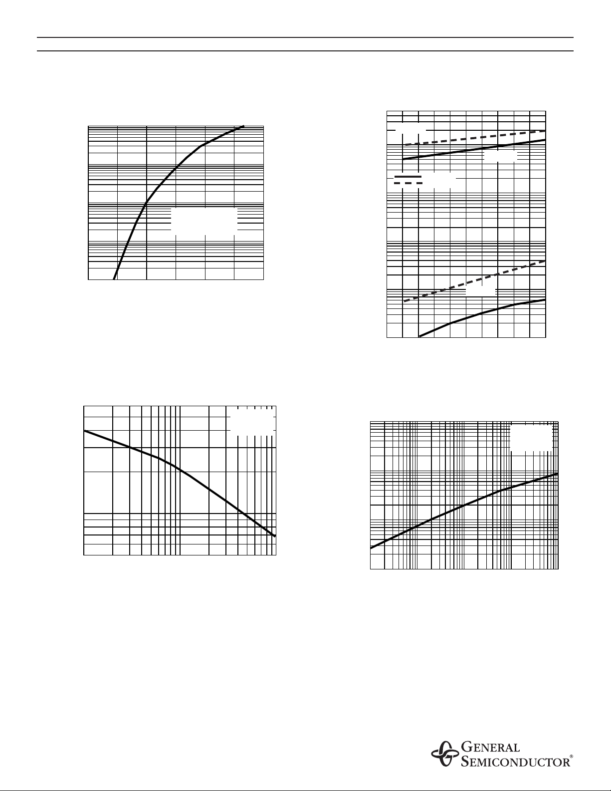
FIG. 5 - TYPICAL INSTANTANEOUS FORWARD
CHARACTERISTICS PER LEG
INSTANTANEOUS FORWARD VOLTAGE, VOLTS
INSTANTANEOUS FORWARD CURRENT,
AMPERES
TJ=25°C
PULSE WIDTH=300µs
1% DUTY CYCLE
PERCENT OF RATED PEAK REVERSE
VOLTAGE, %
FIG. 6 - TYPICAL REVERSE LEAKAGE
CHARACTERISTICS PER LEG
INSTANTANEOUS REVERSE CURRENT,
MICROAMPERES
TJ=25°C
TJ=125°C
TJ=150°C
REVERSE VOLTAGE, VOLTS
FIG. 7 - TYPICAL JUNCTION CAPACITANCE
PER LEG
JUNCTION
,
CAPACITANCE, pF
TJ=25°C
f=1.0 MHz
Vsig=50mVp-p
t, HEATING TIME, sec.
FIG. 8 - TYPICAL TRANSIENT THERMAL
IMPEDANCE PER LEG
TRANSIENT THERMAL IMPEDANCE, °C/W
TJ=25°C
f=1.0 MHz
Vsig=50mVp-p
50-400V
600-1000V
100
600
10
1
0.1
0.01
0.4
0.6
0.8
1 1.2
1.4
1.6
100
10
1
0.1
0.01
0
100
20
40
60
80
100
100
50
10
1
1
10
100
0.1
0.01
0.1
1
10
100

GBPC
FIG. 9
Dimensions in inches and (millimeters)
NOTES:
(1) Corrosion resistant terminals designed with 0.25” female quick connectors for wrap or snap-on
(2) Athin film of silicone thermal compound is recommended between the bridge case and mounting surface for improved thermal conduction
GBPC-W
FIG. 10
Hole for
#10 Screw
0.220 (5.59)
0.200 (5.08)
DIA.
1.135 (28.8)
1.115 (28.3)
0.672 (17.1)
0.632 (16.1)
AC
1.135 (28.8)
1.115 (28.3)
0.310 (7.62)
0.290 (7.36)
0.672 (17.1)
0.632 (16.1)
0.094 (2.4)
DIA.
0.034 (0.86)
0.030 (0.76)
Hole for
#10 Screw
0.220 (5.59)
0.200 (5.08)
DIA.
0.732 (18.6)
0.692 (17.6)
1.135 (28.8)
1.115 (28.3)
0.732 (18.6)
0.692 (17.6)
0.25
(6.35)
0.582 (14.8)
0.542 (13.8)
0.840 (21.3)
0.24 (6.0)
0.18 (4.6)
0.740 (18.8)
1.135 (28.8)
1.115 (28.3)
0.042 (1.07)
0.038 (0.97)
DIA.
0.310 (7.62)
0.290 (7.36)
0.24 (6.0)
0.18 (4.6)
0.470 (11.9)
0.430 (10.9)
0.732 (18.6)
0.692 (17.6)
0.50 (12.7)
0.44 (11.7)
1.25
(31.8)
MIN.
 Loading...