

Page 1
GE Energy
Industrial Solutions
GEH-6256 Installation Instructions
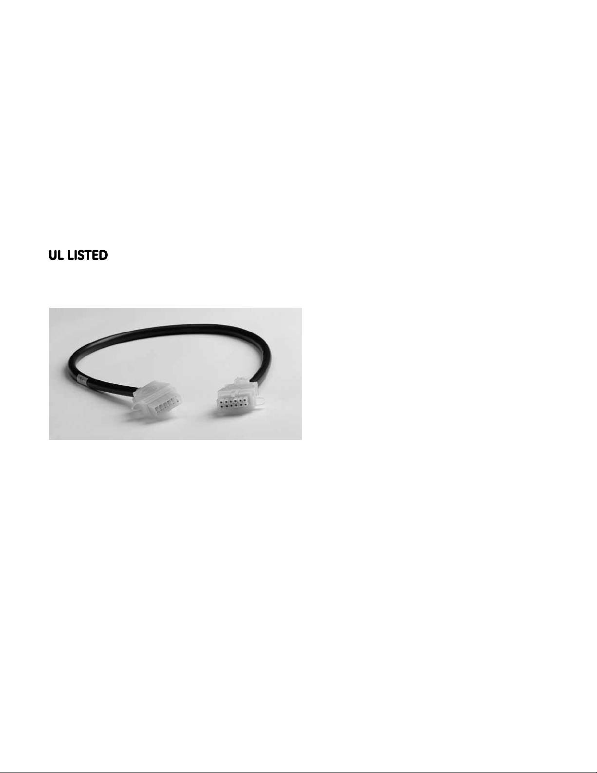
Distribution Cable Extension
For Spectra® RMS Molded-Case Circuit Breakers
TM
with microEntelliGuard
, MicroVersaTrip® PM or MicroVersaTrip® Plus Trip Units
For Catalog Number SDCEA30
Circuit Breaker Accessory
• Voltage Conditioner Assembly
• Distribution Cable Junction Box
• Distribution Cable Extension (Plug End)
• Distribution Cable Terminal Block
• Voltage Module
Plug End of the Cable Extension
• Distribution Cable Harness
• Distribution Cable Extension (Receptacle End)
• Spectra
MicroVersaTrip
• Spectra
MicroVersaTrip
Overview
The General Electric Distribution Cable Extension is
used to provide modular expansion of the Distribution
Cable System. The system is used to carry a variety
of electronic signals between Spectra
Case Circuit Breakers with microEntelliGuard
MicroVersaTrip
Cable Accessories. Accessories supported by the
Distribution Cable Extension are as follows:
Receptacle End of the Cable Extension
• Power Supply Plate
• Voltage Conditioner Plate
• Power Supply Assembly
®
PM/Plus Trip Units and Distribution
®
RMS Molded-
TM
or
• Spectra
microEntelliGuard
cable
The Distribution Cable Extension is 30 inches in length
and can be group-connected to form a longer cable (the
total system cabling length must not exceed 40 feet).
Because both ends of the Distribution Cable Extension
are different (receptacle end / plug end), you cannot use
it for connections between Spectra
Circuit Breakers and Distribution Cable Accessories;
use the Distribution Cable Harness (Cat. Nos. SDCHA11,
SDCHA30 or SDCHA60) for this application.
®
RMS Molded-Case Circuit Breaker with
®
®
RMS Molded-Case Circuit Breaker with
®
RMS Molded-Case Circuit Breaker with
Plus Trip Unit and breaker cable
®
PM Trip Unit and breaker cable
TM
Trip Unit with a 12-pin breaker
®
RMS Molded-Case
Page 2
GEH-6256 Installation Instructions
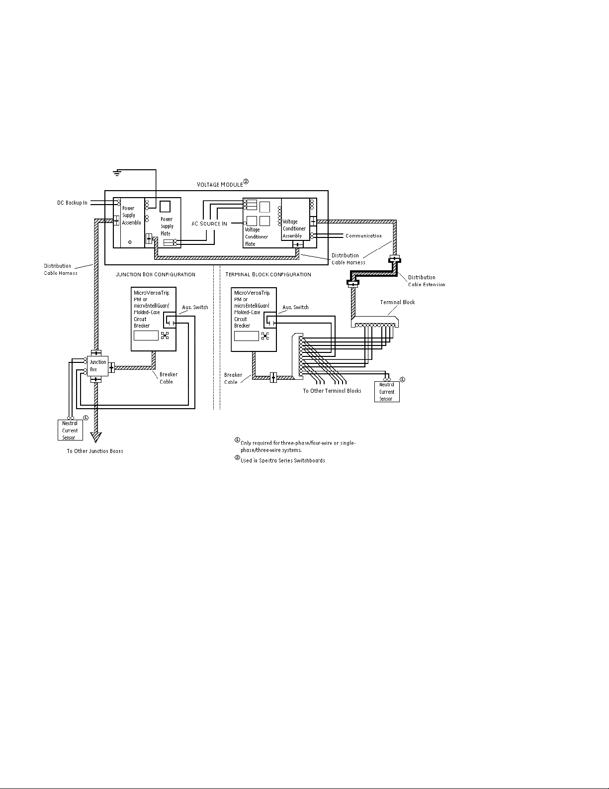
Figure 1 shows how the Distribution Cable Extension is used in a typical MicroVersaTrip® PM system. Figure 2
®
shows how the Distribution Cable Extension is used in a typical MicroVersaTrip
TM
microEntelliGuard
diagram shown in Figure 2 applies to microEntelliGuard
Trip Unit can be used with either configuration, i.e. Figure 1 or Figure 2. The connection
TM
Trip Units with Basic Metering.
Plus system. The
Figure 1. Typical MicroVersaTrip® PM Trip Unit System detailing the Distribution Cable Extension.
Page 3
GEH-6256 Installation Instructions
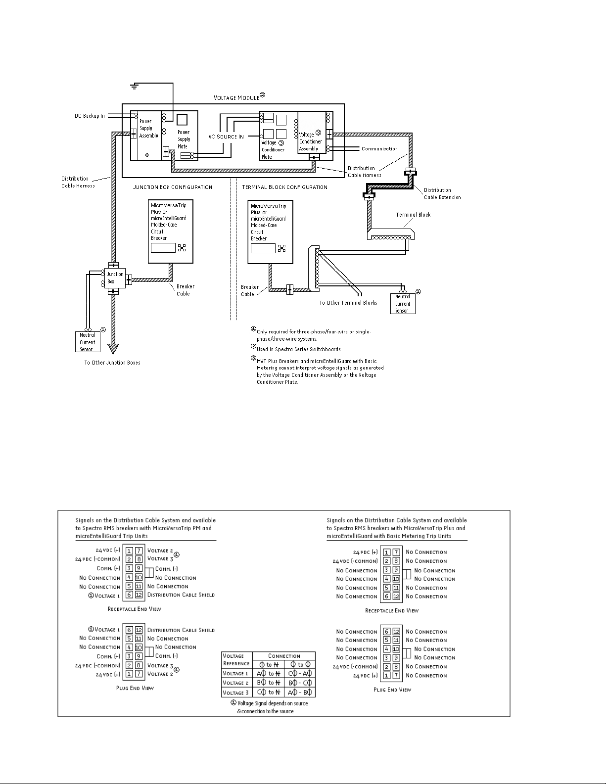
Figure 2. Typical MicroVersaTrip® Plus Trip Unit System detailing the Distribution Cable Extension.
Figure 3. End view of Distribution Cable Extension detailing available pinout connections.
Page 4

GEH-6256 Installation Instructions
The electronic signals supported by the Distribution
Cable Extension vary depending on the type of trip unit
used; a list of supported functions is as follows.
®
Spectra
MicroVersaTrip
RMS Breaker with microEntelliGuardTM or
®
PM Trip Unit
• Control power (+24vdc)
• Control power (-common)
• System communications (Comm. +)
• System communications (Comm. -)
• Voltage A f (must be from Voltage Module or Voltage
Conditioner Plate or Voltage Conditioner Assembly)
• Voltage B f (must be from Voltage Module or Voltage
Conditioner Plate or Voltage Conditioner Assembly)
• Voltage C f (must be from Voltage Module or Voltage
Conditioner Plate or Voltage Conditioner Assembly)
®
Spectra
microEntelliGuard
RMS Breaker with MicroVersaTrip® Plus or
TM
(with Basic Metering) Trip Unit
• Control power (+24vdc)
• Control power (-common)
Figure 3 shows the connector pinout for the Distribution
Cable Harness for each type of trip unit.
To disconnect the Distribution Cable Extension, press
down at the rear of the receptacle interlock until the
interlock clears the hook and remove the receptacle
(see Figure 5).
Figure 4. Side view of receptacle-plug connection insertion.
Connections
The Distribution Cable Harness contains a 12-pin
receptacle connector on each end. The connectors are
keyed so they cannot be inserted incorrectly into a
mating 12-pin plug connector.
To connect the end of the Distribution Cable Extension
to another Distribution Cable Accessory, align the
receptacle interlock with the plug hook and insert the
receptacle into the plug until the interlock and hook
overlap and catch (see Figure 4).
Figure 5. Side view of receptacle-plug connection removal.
Page 5

GEH-6256 Installation Instructions
Additional Information
Refer to these other user’s manuals for more details:
®
GEH-5934 MicroVersaTrip
PM Trip Units in Spectra
Plus and MicroVersaTrip®
®
RMS Molded-
Case Circuit Breakers
®
GEH-700 Spectra
G Breaker w/
microEntelliGuard™ Trip Unit
®
GEH-701 Spectra
K Breaker w/
microEntelliGuard™ Trip Unit
GEH-702 microEntelliGuard™ Trip Unit Users Manual
DEH-41318 Universal Rating Plug
GEH-6250 Voltage Module
GEH-6251 Power Supply Plate
GEH-6252 Voltage Conditioner Plate
GEH-6253 Power Supply Assembly
GEH-6254 Voltage Conditioner Assembly
GEH-703 MET Battery Pack Adapter
GEH-704 MET Advanced Distribution Cable
Junction Box
DEH-006 Distribution Cable Junction Box
GEH-705 MET Distribution Cable Extension (20-pin)
GEH-6255 Distribution Cable Harness (12-pin)
GEH-706 MET Distribution Cable Terminal Blocks
(11 point & 22 point)
GEH-6257 Distribution Cable Terminal Block (11 point)
GEH-6491 POWER LEADER™ Modbus Concentrator
GEH-6502 POWER LEADER™ PMCS 5.0 Network
Architecture Guide
GEH-707 MET Sealable Cover kits
DEH-4568 GTU digital test kit (GTUTK20)
GEH-5551 Shunt Trip and UVR instructions
GEH-5593 Aux switch and bell alarm
GEK-64467 TIM-1 Zone Selective Interlock Module
Page 6

GEH-6256 Installation Instructions
Notes
Page 7

GEH-6256 Installation Instructions
Notes
Page 8

Spectra and MicroVersaTrip are registered trademarks and EntelliGuard and
microEntelliGuard are trademarks of the General Electric Company.
These instructions do not cover all details or variations in equipment nor do they
provide for every possible contingency that may be met in connection with installation,
operation, or maintenance. Should further information be desired or should particular
problems arise that are not covered sufficiently for the purchaser’s purposes, the
matter should be referred to the GE Company.
GE Energy
41 Woodford Avenue, Plainville, CT 06062
www.geelectrical.com
© 2011 General Electric Company
imagination at work
GEH-6256 Rev. 3 (11/11 M45)
 Loading...