

Page 1
GE Consumer & Industrial
NOTES
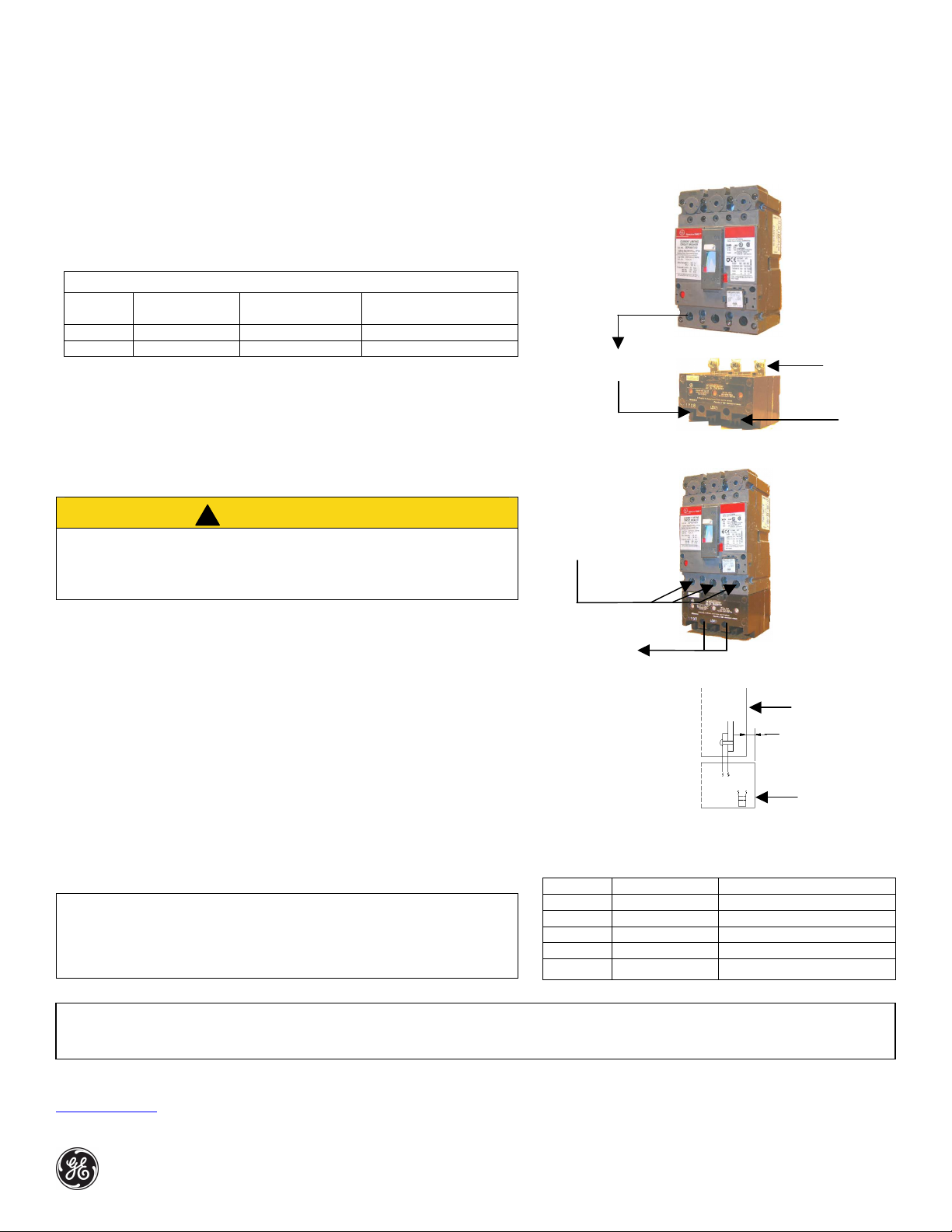
Secure limiter to
lugs to limiter
!
load terminal
28 screws
ontingency that may be met in connection with installation, operation
Figure 2
limiter
Figure
3
0.056”
Electrical Distribution
SAXSEL, SAXSEP Current Limiter
Installation Instructions DEH-4671
For use with 3 pole type SEL/SEP Spectra® RMS circuit breaker.
Instructions:
Select a 3 pole Type SEL/SEP Spectra® RMS circuit breaker with its ampere rating
equal to or less than the SAXSEL, SAXSEP current limiter’s ampere rating.
CATALOG NUMBER
Ampere
Rating
150 SAXSEL36150 65,000 (Sym) SELA36*******
150 SAXSEP36150 100,000 (Sym) SEPA36*******
Contents of kit:
1. Qty (1) SAXSEL or SAXSEP current limiter.
2. Qty (3) 1/4 - 28 X 1/2” screws.
3. Qty (2) 8 –32 X 2-7/8” screws.
Add ON Limiter Interrupting rating
at 600V
For use with circuit
breaker catalog type
CAUTION
1. When installing accessories, the breaker must be completely deenergized
and disconnected from the electrical circuit.
2. Connect the current limiter on the load end of the circuit breaker.
Assembly Instructions:
1.
Remove lugs (if present) from load end of circuit breaker.
2. Attach current limiter line terminals to circuit breaker load terminals using (3)
1/4 - 28 screws provided. Torque to 30 – 35 in. lbs (Figure 2)
3. Attach qty (3) lugs (not provided) to current limiter load terminals.
(Select lugs for limiter from Table 1).
4.
Mount the breaker/limiter assembly into equipment using mounting screw kit
SEMSK1 or SEMSK3 (not provided). Caution: The back surface of the limiter
does not lie in the same plane as the back surface of the breaker (figure 3). If
the mounting surface of the equipment extends in back of the limiter,
accommodate the offset by shimming the breaker or offsetting the mounting
surface. Securing the limiter to the mounting plate is optional - use qty (2) 8 32 screws provided (Figure 2 & 3).
:
1. SAXSEL/SAXSEP current limiter can be used with 3 pole Type SEL/SEP Spectra®
RMS motor circuit protector however, the interrupt rating is based on evaluation
as part of a combination motor controller per UL508/845.
2. If plunger(s) is extended, current limiter must be replaced.
These instructions do not cover all details or variations in equipment nor do they provide for every possible c
or maintenance. Should further information be desired or should particular problems arise that are not covered sufficiently for the purchaser’s purposes, the matter should be
referred to the GE Company. The breaker is a sealed unit, which contains no user serviceable parts. Tampering with seal will void warranty.
Transfer breaker
Attach
current
limiter to
circuit
breaker’s
with (3) ¼ -
the mounting
plate with (2) 8 –
32 screws, if
needed (refer
Figure 3)
Table1
LUG AMPACITY WIRE RANGE
TCAL14 15–30 A (1) # 14-8 Cu, # 12-8 Al
TCAL12 15–60 A (1) # 14-3 Cu, # 12-1 Al
TCAL12A 70–90 A (1) # 6-2/0 Cu, # 4-2/0 Al
TCAL15 100–150 A (1) # 3-3/0 Cu, # 1-3/0 Al
TCAL18 15–150 A (1) # 12-3/0 Cu/Al
Figure 1
Circuit
breaker
load end
Current
limiter
terminals
line end
Back plane
of circuit
breaker
Back plane
of current
Current
limiter
terminals
load end
GE Consumer & Industrial
41 Woodford Avenue, Plainville, CT 06062
www.geelectrical.com
© 2007 General Electric Company
DEH-4671 R01 (11/04)
 Loading...