

Page 1
GE Consumer & Industrial
Electrical Distribution DEH-41467
Operation & Maintenance Manual
Catalog # EGGRRLV
115 VAC, 60 Hz
Low Voltage Entelliguard G
Circuit Breakers
Remote Racking
Operator
For Entelliguard G
Breakers 400A-6400A
1
Page 2
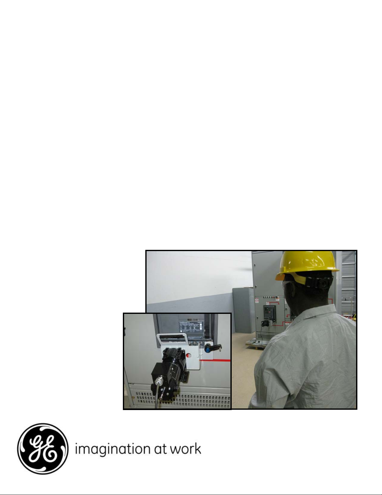
Section 1. Introduction
The remote racking operator allows the user
to move a draw out circuit breaker between
the CONNECT and DISCONNECT positions via
an electric racking gear head motor and the
Cassette housing the breaker. The remote
racking operator requires 115VAC, 60Hz
control power. A control box connected to the
operator with a thirty-foot chord permits
control from a remote location.
Section 2. Receiving, Handling and
Storage
2.1 Receiving and Handling
Each Remote Racking operator is carefully
inspected and packed for shipment.
Immediately upon receipt of the device an
examination should be made for any damage
sustained in transit. If injury or rough handling is
evident, a damage claim should be filed
immediately with the transportation company,
and the nearest General Electric Sales Office
should be notified.
WARNING: Danger of electrical shock or
injury. Ensure ALL electrical power
supplies are « OFF « before installing or
removing any devices. Ensure the breaker
is in the OFF position before racking from
the disconnected to connect position or
from connect to disconnect. The breaker,
trip unit or accessories MUST ONLY be
installed and serviced by QUALIFIED
personnel, see NEMA publication Ab4.
Avertissement : Danger de electrocution ou
de blessure. S ‘assurer avant TOUTES
manipulations du disjoncteur que les
differentes sources d’alimentation sont en
position « OFF ». S’assurer que le
disjoncteur est en position « OFF » avant
montage dans la position branchee a partir
de la position debranchee et.ou mantage
dans la position de’branchee a’ partir de la
position branchee. Les disjoncteurs,
unites de protection ou accessoires
doivent etre installes par des personnes
qualiffees et habilitees. Voir NEMA
publication Ab4.
The device should be removed from the shipping
box with sufficient care so that no damage will
result from rough handling. “Loose parts”
associated with the apparatus may be included
in the crate. Care should be taken to make
certain that these parts are not overlooked.
2.2 Storage
The remote racking operator should be
protected against condensation, preferably by
storing it in a warm, dry environment at
moderate temperatures such as 40 degrees F to
100 degrees F. The storage area should be clean
and contain no corrosive gasses.
If the device is stored for any length of time, it
should be inspected prior to use to insure its
proper mechanical and electrical working
condition.
2
Page 3

Section 3. Attachment / Removing
Attaching the Remote Racking Operator to the
breaker cassette.
Tool needed: Regular flat head screwdriver
approximately 8 inch long shank.
Warning: GE breaker cassettes mounted in AKD20 switchgear is equipped with a steel mounting
tube assembly. OEM breaker cassettes are
equipped with a plastic tube for holding the
manual racking tool. PLASTIC TUBES ARE NOT
ACCEPTABLE FOR MOUNTING THE REMOTE
RACKING OPERATOR. The proper mounting tube
assembly is part number 0275B8280G001. If the
cassette has the plastic tube you must order this
part for each cassette and replace the plastic tube
(see page 5 for cassette identification).
1. Attach the Remote Racking Operator to the
Entelliguard G breaker cassette by first
locating the port located to the far right of
the cassette lower facia (see fig. 1). There are
three ports located on the cassette bottom
facia. The other two are for Kirk Locks.
2. Depressing the blue button on the quick lock
pin (1 fig. 2), insert the pin into the Port.
Depressing the button allows the two detent
pins to retract allowing insertion. Align the
hex bit driver with the racking driver port, (2
fig. 2).
3. Insert the bit while at the same time turn the
racking access door screw clockwise, (3 fig.
3) with the screwdriver.
4. Apply forward pressure to engage and seat
the hex drive bit. If the hex bit wont insert
then the hex male bit is not aligned with the
hex female drive in the cassette. Rotate the
motor shaft exiting the rear of the motor
body until the bit aligns while pushing the
racking operator handle. When they are in
alignment, the Remote Racking Operator will
slide further into the cassette. When the
racking operator is fully inserted you will hear
the detent pins on the Kwik lock shaft click
into the locked position. Pull the racker back
slightly to confirm locked condition.
Before operating the racking operator make
sure you have positioned yourself at least 25
feet away from the breaker. Proceed to
section 4.
Fig. 1 Remote Racking Operator mounting Port.
Fig. 2 Inserting racker operator
Fig. 3 Opening Racker access door
3
Page 4

Description and Operation
Section 4.1 Description
Remote Racking Operator – 400-6400A
frame size Entelliguard
The remote racking operator consists of a drive
train, control box with switches, power chord
and connecting chord. The drive train is made of
a gear head motor (1, fig. 4). The hand held
control box consists of an (OFF/ON) toggle switch
(2, fig. 5). A forward, stop, reverse (FWD STOP
REV) three position toggle switch (3, fig. 5). A
(RUN), momentary push button (4, fig. 5). And a
two position torque selector toggle switch
labeled (BREAKER FRAME) with choices Frame 1/
2, left position and Frame 3, right position.
(5, fig. 5). After plugging in the grounded 3pronged power chord to a 115V AC outlet, the
OFF/ON toggle can be switched to ON which
powers up the control box. Depending on the
breaker frame size being racked in or out, toggle
this switch to the appropriate position. Refer to
the Breaker Envelope Frame Size chart on page 5
to determine the envelope frame size of the
breaker you are racking. Next step is to
determine which intended direction the breaker
will go. If breaker is in the DISCONNECTED
position then the intended direction would be
forward (FWD) to rack to the connected position.
If the breaker is in the CONNECTED position then
the intended direction is reverse (REV). Existing
breaker position is confirmed by the position flag
in the lower left location of the breaker cassette
facia plate located below the breaker. There is a
window indicating the breakers position. Before
Racking breakers in or out, ensure breaker is in
the OFF position. See Warning on page 1.
G breakers
Fig. 4 Remote Racking Operator drive train
or DISCONNECTED the controller will sense the
increase in current and shut off power to the
motor. An LED labeled “TORQUE LIMIT” , (6, fig 5)
will illuminate signaling end of stroke. Remove
pressure from the (RUN) button. There is also a
striped label on the motor shaft exiting the rear
of the motor. This can be used for a visual
reference for when the breaker has reached the
final positions.
1
TORQUE LIMIT
Section 4.2 Operation
Next step is to depress the momentary
pushbutton, (RUN) which will start the drive.
Hold down the button until the breaker reaches
final position. The drive controller is equipped
with a current inrush sensor. When the breaker
reaches it’s end of stroke whether CONNECTED
Fig. 5 Control Box
4
Page 5

Breaker Envelope Frame Size Chart
In the catalog number printed on the breaker label, the 5th digit is identified as the breaker type and can
be found in the first column in the table below. Determine the envelope frame size by looking up the
breaker type and finding the Amp rating. The chart will show which envelope the breaker falls under.
Interrupting Rating Tier ANSI/UL1066 Devices, LVPCB Frame 1 Frame 2 Frame 3
Type 240 V 480 V 600 V 1/2S Withstand 400 to 2000 3200 400 to 3200 3200 4000 to 5000
N 65,000 65,000 65,000 65,000 X X
H 85,000 85,000 65,000 85,000 X
E 85,000 85,000 85,000 85,000 X
M 100,000 100,000 85,000 85,000 X X
B 100,000 100,000 100,000 100,000 X X
L 150,000 150,000 100,000 100,000 X X
Mounting Tube Accessory For OEM Breaker
Cassette
The OEM cassette is equipped with a black plastic
racking handle storage tube. If you have an OEM
cassette the plastic part needs to be removed and
this part needs to be installed. To identify an OEM
breaker, the sixth character in the 20-digit catalog
number will be 1, 2 or 3 if it is an OEM breaker. If the
sixth digit is a D, then it is an AKD-20 cassette.
Hardware for mounting the metal tube is already in
the cassette. The nut needs to be loosened, slide in
the tube from the side and retighten the nut to 25 lbin. See figures 6 and 7
Part number 0275B8280G001
Fig 7. Mounting Tube Assembly. Part No.
0275B8280G001
Section 4.3 Replacing Fuse
Fig 6. Installing the mounting tube
Fig 8. Enclosure Fuse Holder
The enclosed drive is protected by an accessible
fuse as shown in figure 8. To replace the fuse,
turn the fuse holder cap counter-clockwise and
remove the 8A 250 volt fuse and replace with a
fuse of the same size and rating.
5
Page 6

These instructions do not purport to cover all details or variations in
equipment nor to provide for every possible contingency to be met in
connection with installation, operation or maintenance. Should further
information be desired or should particular problems arise which are
not covered sufficiently for the purchaser’s purposes, the matter should
be referred to the General Electric Company.
DEH-41467 R01 0210
GE Consumer & Industrial
41 Woodford Avenue
Plainville, CT 06062
USA
www.geelectrical.com
2009 General Electric Company
6
 Loading...